Article

Probing the Deformation Mechanisms of Nanocrystalline Silver by In-Situ Tension and Synchrotron X-ray Diffraction

Clean Nano Energy Center, State Key Laboratory of Metastable Materials Science and Technology, Yanshan University, Qinhuangdao 066004, China
*
Author to whom correspondence should be addressed.
Metals 2020, 10(12), 1635; https://doi.org/10.3390/met10121635
Submission received: 9 November 2020 / Revised: 30 November 2020 / Accepted: 3 December 2020 / Published: 5 December 2020

Abstract

:
The mechanisms responsible for the deformation of nanocrystalline materials are not well understood although many mechanisms have been proposed. This article studies the room-temperature stress-strain relations of bulk nanocrystalline silver deformed in a tension mode at a constant strain rate. Synchrotron X-ray diffraction patterns were gathered from the deformed specimen and used to deduce such structural parameters as the grain size and the density of dislocations, twins, and stacking faults. Our quantitative results indicate that grain growth and twinning occur in the stage of elastic deformation. Detwinning and accumulation of stacking faults occur in the early stage of plastic deformation, where the strength of nanocrystalline silver correlates well with the square root of stacking faults probability. Grain shrinking and generation of statistically stored dislocations occur in the final stage of plastic deformation, where the strength of nanocrystalline silver correlates well with the square root of the density of dislocations (statistically stored and geometrically necessary). Our results suggest that multiple deformation mechanisms such as grain growth, grain shrinking, twinning, detwinning, stacking faults, and dislocations, rather than a single deformation mechanism, occur in the elastic and plastic deformation stages of nanocrystalline silver.

Graphical Abstract

1. Introduction

Extensive studies have been performed in the past decades, aimed at understanding the unique mechanical properties of nanocrystalline (nc) metals. Many mechanisms, which are distinct from the well-known dislocation pile-up mode proposed for conventional coarse-grained metals, have been proposed for the plastic deformation of nc metals [1,2,3]. Recent studies suggest [4,5,6,7] that the mechanical performance of nc metals and alloys are strongly affected by both grain size and grain boundary segregation.
In order to examine the unique deformation mode of nc metals, researches have performed many in situ studies, which include (i) the observation of deformation behavior in nc films under transmission electron microscope (TEM); and (ii) the detection and analysis of synchrotron X-ray diffraction (SXRD) profiles collected during the deformation of nc metals. Results for these in situ studies are summarized in Table 1, where nc Au, Ni, Pd and Pt with a grain size between approx. 5 and 50 nm have been studied. Table 1 suggests that (i) either a single mechanism or multiple mechanisms have been proposed for a given nc metal; (ii) the mechanisms are affected by the grain size; and (iii) the proposed mechanisms are different even for the same nc metal, e.g., nc Ni. In particular, these studies predict many different deformation mechanisms, such as grain rotation [8,9,10], grain boundary (GB) motion [9] and migration [11,12,13,14] or twinning/detwinning [9,15], grain growth [9,11,15], cross-grain dislocations [10,12], dislocation emission [13] or nucleation from GBs [16], dislocation absorption by GBs [13,16], dislocation storage [17,18], full dislocations and the Lomer locks [19], partial dislocations generating stacking faults [19], and competition between dislocation-based and GB-mediated mode [20].
Clearly, the deformation process of nc metals can be complicated and thus needs further study. In addition, in-situ observation in TEM only examines the deformation in a small two-dimensional region where surface of the specimen may alter the deformation behavior. It has been proposed that the free surfaces on the thin films used for the in situ TEM studies may intensify dislocation activities and lower dislocation storage [16]. Thus, the deformation behavior that occurs in a two-dimensional region does not necessarily represent that inside a three-dimensional bulk nc specimen. In addition, it has been found that the electron beam exposure under a TEM can activate dislocations, relax stress, and abnormally neck the specimen in nc Al and Au films [21].
In order to better comprehend the deformation mode of nc metals, we performed quantitative experimental studies by monitoring the macroscopic stress-strain relations of bulk nc silver (nc-Ag) in tension and simultaneously recording the SXRD patterns. We further quantitatively analyzed the X-ray diffraction (XRD) diffraction data to deduce such structural parameters as the grain size and the density of twins, stacking faults, and dislocations. Based on these quantitative studies, we have found multiple deformation modes in our elastically and plastically deformed nc-Ag.

2. Materials and Methods

We used an in situ refinement/consolidation technique [22] to prepare bulk nc-Ag. Eight grams of coarse-grained silver powders (60–80 mesh, 99.99% pure, supplied by Alfa Aesar) were placed into a hardened-steel vial together with forty 1-gram hardened steel balls. The vial was mechanically milled at room temperature for 24 h in a SPEX-8000 mill (SPEX SamplePrep, Metuchen, NJ, USA), which was placed inside a glove box (Etelux, Beijing, China) filled with argon and free from oxygen and moisture. In order to prevent the contamination of iron, we only used the specimens prepared in the second batch. The mechanical milling in the first batch was used to coat relatively soft silver on the surface of the milling vial and balls. As a result, no iron element was detected in nc-Ag by energy dispersive X-ray analysis available in a S-4800 scanning electron microscope (Hitachi High-Tech Corporation, Tokyo, Japan). After the mechanical milling, coarse-grained silver powders are repeatedly fractured and cold-welded to form bulk silver spheres with diameters ranging from 4 to 10 mm. The severe plastic deformation generated in the mechanical milling process results in a nanocrystalline microstructure in as-prepared bulk silver spheres, as confirmed by both TEM and XRD techniques described in this article. We measured the density of the as-synthesized silver specimens by the Archimedes’ method. The measured density is 99.7% of the theoretical density of conventional coarse-grained silver, suggesting that our silver spheres contain negligible porosity. We further characterized the silver spheres by a JEM-2010 TEM (JEOL Ltd., Tokyo, Japan). The as-synthesized silver sphere was first pressed to form a flat disk with a thickness of ~1 mm, then mechanically polished to be ~30 micron thick, and finally thinned by ion milling at 5 keV in a vacuum (3 × 10⁻³ Pa). For tensile testing, the disks were machined as tensile specimens, which are flat, dog-bone shaped, and with gauge thickness, width, and length of 0.48, 1.25, and 3 mm, respectively. The surface of the machined specimen was mechanically polished using 0.3 µm diamond paste.
We then used monochromatic high-energy X-ray to collect the XRD profiles during the deformation of nc-Ag. The X-ray is with an energy of 80.715 keV and a wavelength of 0.15388 Å. The synchrotron XRD profiles were recorded with the hard X-ray synchrotron-radiation facility at Argonne National Laboratory. The diffraction patterns were collected in situ as the sample was loaded in a custom-built tensile fixture in displacement control. The loading regime was step-wise, i.e., the sample was kept at a certain displacement increment for each step during which the diffraction data were collected. The data are gathered from the entire thickness of the sample since the high energy X-rays penetrated the 0.48 mm thick sample. The beam size was 200 × 200 μm2 whereas the distance between the detector and the loaded specimen was 1.44 m. Since the Bragg angles are only within 2–4°, entire diffraction rings for Ag 111, 200, 220, 311 and 222 reflections can be collected by a GE Revolution 41RT area detector (GE Research, Niskayuna, NY, USA) with an area of 41 × 41 cm2 and a pixel size of 200 × 200 μm2. At each load, a 10° slice of the diffraction rings was binned to form the one-dimensional patterns. All the diffraction data used in this paper are based on those recorded at a position parallel to the tensile axis. In addition, no instrumental broadening profile could be successfully obtained with this detection technique since the coarse-grained reference sample does not contain sufficient number of grains inside our beam size area (200 × 200 μm2). As a result, diffraction spots overlap continuous diffraction rings, leading to the scatter in the intensity around the diffraction rings. However, this should not influence our conclusion. For the determination of macroscopic strains, the sample was painted with a speckle pattern prior to the experiment. Then, optical images during the deformation were recorded and analyzed to yield the macroscopic strains.
We further used the profile fitting program [23] to analyze the synchrotron XRD profiles of deformed nc-Ag to simultaneously extract two important structural parameters: grain size and dislocation density. For this purpose, the grain size coefficient and the lattice distortion coefficient are first extracted from the Fourier coefficients of the diffraction profiles [24]. Then, the grain size coefficient can be used to calculate the volume-weighted mean column length D (XRD grain size) whereas the lattice distortion coefficient can be used to deduce the density of dislocations. More details about the profile fitting program are described in reference [23].
Since silver is with a relatively low stacking fault energy of approx. 20 mJ/m2 [25], such defects as twins and stacking faults tend to develop during deformation. The stacking fault probability ( α S F ) can be extracted either from the position of the XRD peaks [26], or more accurately from the relative changes between two neighboring peaks, e.g., (111)–(200), (200)–(220), and (220)–(311) neighboring pairs [27,28]. α S F is related to the peak shifts [28,29]:
Δ ( 2 θ 0 ) h k l Δ ( 2 θ 0 ) h k l = H α S F
where H is a parameter dependent on the neighboring pairs [27].
Because a diffraction peak can be asymmetrically broadened by twin faults, the twinning probability β for metals with a face-centered cubic (fcc) structure can then be measured from the peak asymmetry of (111) and (200) peaks [30], i.e.,
β =   [ 2 θ 111   ( P C )     2 θ 111   ( P M ) ]     [ 2 θ 200   ( P C )     2 θ 200   ( P M ) ]   11   t a n θ 111   +     14.6   t a n θ 200
where PC and PM represent the gravity center position and the peak maximum position, respectively.

3. Results

Shown in Figure 1 is the TEM image of as-prepared nc-Ag. The grains are approximately equiaxed and with a size ranging from 8 to 20 nm. Counting 50 grains gives an average grain size of 13.5 nm.
Shown in Figure 2 is the macroscopic stress ( σ T S ) and strain ( ε T S ) relation for bulk nc-Ag deformed in tension. For clarity the data are classified into five regimes, which are marked by dashed ovals and will be used to discuss our results through our paper. In Regime I, deformation is elastic. Regime II covers a strain range between 0.24% and 0.80%, corresponding to a plastic strain between 0 and 0.2%. In Regime III, total strain increases from 0.80% to 1.3%. In Regime IV, the specimen was unloaded to zero stress and reloaded to a stress close to that (~320 MPa) before unloading. Finally, loading was continued to reach a total strain of ~3% in Regime V. The yield strength ( σ 0.2 ), as conventionally defined at 0.2% plastic strain, is 265 MPa for nc-Ag. In comparison, the yield strength of coarse-grained (>10 µm) silver is below 76 MPa [31].
Linearly fitting the stress-strain curve in the elastic regime (Regime I) of Figure 2 gives a Young’s modulus of approx. 42 GPa, which is much lower than that, 82.7 GPa [32], of coarse-grained silver. This discrepancy could result from two factors. First, the large fraction of grain boundaries and triple junctions in nc metals and alloys lowers their Young’s moduli [33]. Second, the specimen during a tension test may be misaligned and bended, making the Young’s modulus uncertain and scattered [34].
Dependence of the full width at half maximum (FWHM) for the reflections of nc-Ag on the (macroscopic) true strain ( ε T S ) is shown in Figure 3. For clarity, only FWHM values of the (111) and (200) peaks are displayed. The FWHM decreases significantly within Regimes I and II. For a plastic strain >0.2% (Regimes III and V), the FWHM only slightly increase. During the unloading-loading deformation (Regime IV), the FWHM for reflection (200) remains almost constant but the FWHM for reflection (111) decreases.
Figure 4 shows the dependence of macroscopic true stress ( σ T S ) on microscopic lattice strain ( ε L S ) for four reflections of nc-Ag, (111), (200), (220) and (311). Here the lattice strain εLS is calculated for each reflection (hkl) by expression ε L S = a(hkl)/a0 − 1, where a0 and a(hkl) are the lattice parameter of as-prepared and tension-deformed nc-Ag, respectively. The dashed horizontal line in Figure 4 represents the macroscopic σ 0.2 yield stress (265 MPa) whereas the solid straight lines in this figure represent linear (elastic) stress-strain behavior. For clarity the data points in the unloading-loading regime (Regime IV in Figure 2) are not shown. It can be seen that the softest reflection (200) starts non-linearity at ~150 MPa. In comparison, the stiffest reflection (111) starts non-linearity at ~300 MPa. Occurrence of this non-linearity is indicative of the starting of plastic deformation.
Figure 5a shows the change of grain size (D) with tensile deformation. Although uncertainty (error bar) for each grain size is ~1 nm, relatively large when compared with the change in grain size, the tendency for the change in grain size is clear. Grain size increases mainly in the elastic regime (Regime I). After plastic deformation starts (Regimes II and III), grain size remains almost constant. Unloading in Regime IV completely recovers the grain size. Deformation in Regime V decreases the grain size. Interestingly, note that the grain size determined from TEM is only approx. one third of the grain size—the volume-weight mean column length—determined from the XRD peak broadening.
The change of dislocation density (ρ) with true strain ( ε T S ) is shown in Figure 5b. ρ slightly decreases by ~3.5% in the elastic regime (Regime I). After plastic deformation starts, ρ remains almost constant in Regime II and slightly increases by ~1.8% in Regime III. The dislocation density can be completely recovered after unloading in Regime IV, suggesting that no dislocation can be stored in this stage. ρ largely increases by ~14% in Regime V.
The strength of a plastically deformed metal can be increased by the deformation-generated dislocations. The relation between shear stress τ and dislocation density ρ often follows the well-known work-hardening equation, τ = τ 0   + α Gb ρ 1/2, where τ 0 , G, and b are a material constant, shear modulus, and Burger vector, respectively, and α is a constant of the order of 0.2 and 0.5 for most coarse-grained metals. In tension, this expression can be converted to σ = σ 0 + α M Gb ρ 1/2, where σ is tensile stress, σ 0 is the friction stress caused by all obstacles excluding dislocations, and M (~2) is the Taylor factor. In Figure 6, we plotted σ T S as a function of ρ1/2 for nc-Ag plastically deformed in Regimes III and V. The data in both regimes follow an expected linearity. However, their slopes are largely different, indicative of significantly different α values. α in Regime III is determined to be 3.4 ± 0.2, an order of magnitude larger than that (0.34 ± 0.03) in Regime V. Notice the fact that in coarse-grained (~20 μm) silver, the relation between stress and dislocation density (measured by TEM) gives a α value of 0.47 [35], close to that found within Regime V for the nc-Ag.
The density of geometrically necessary dislocations (GNDs), ρg, is inversely proportional to grain size, D, i.e., ρg = ε/4bD, where ε is strain and b is Burger vector [36]. The total density of dislocations (ρ) versus ε T S /D for nc-Ag deformed in Regimes III and V is plotted in Figure 7. Data within Regime III do follow a linear relation with a slope of 0.98 ± 0.08 nm−1, in good agreement with the predicted 1/4b value (0.86 nm−1) for silver with b = 0.29 nm. Data within Regime V, however, clearly deviate from those predicted with the GNDs model. Thus, there are excess dislocations in Regime V. Density of the excess dislocations is the difference between the (measured) total dislocation density and the (predicted) GNDs density.
Figure 8a shows the dependence of stacking fault probability α S F on true strain ε T S . α S F is close to zero in the elastic regime (Regime I). α S F increases with strain in Regimes II and III. Surprisingly, α S F is not lowered by unloading in Regime IV, suggesting that the stacking faults can be stored in nc-Ag. α S F slightly increases with strain in Regime V.
Figure 8b shows the dependence of twinning probability β on true strain ε T S . β increases with strain in the elastic deformation regime (Regime I) but decreases with strain after plastic (Regimes II and III). Unloading to zero stress (Regime IV) almost recovers the value of β. Clearly, no twins can be stored in Regimes II and III. Instead, the twinning probability seems to be lowered with deformation. However, the twinning probability largely increases with strain in Regime V.
Figure 8 suggests that twining occurs in the stage of elastic deformation where detwinning and stacking faults occur in the early stage of plastic deformation. In deformed coarse-grained silver and silver-based alloys, α S F and β are comparable (both at a magnitude of ~10−2) [37]. In our plastically deformed nc-Ag, β (~10−4) << α S F (~10−2). The highest value of β, 2 × 10⁻⁴, achieved in our deformed nc-Ag corresponds to two twins in ten thousand atomic layers. The (111) plane of silver has a lattice spacing of 0.24 nm. Ten thousand atomic layers are spread over a distance of 2400 nm, ~100 times of the grain size. Thus, twinning should not be the primary plastic-deformation mechanism in our nc-Ag. This can be further supported by the fact that the applied stress increases largely from ~120 to 320 MPa in Regimes II and III. However, twinning probability β decreases in these two regimes. By contrast, the true stress σ T S strongly correlates with the square root of α S F , as shown in Figure 9 where the a linear relation between σ T S and α S F 1/2 is observed for our plastically deformed nc-Ag in Regimes II, III, and V.

4. Discussion

4.1. Stage 1: Grain Growth and Twinning

In the elastic deformation regime (Regime 1 in Figure 2), dislocation density decreases whereas grain size and twinning probability increase with strain. No stacking fault is generated. Note that for nc Ni, the dislocation density also slightly decreases with strain in the elastic deformation regime [18].
The growth of grains under strain (or stress) has been observed in many nc metals [9,11,15,38,39,40,41,42,43,44,45,46,47]. This strain- or stress-induced grain growth may be caused by grain boundary migration [48], grain rotation and coalescence [41,46], or a combination of these two factors [49]. The present study cannot tell whether these factors are applicable to the grain growth observed in nc-Ag. In addition, our results indicate that the average grain size increases by only ~1 nm in Regime I, as shown in Figure 5a. This slight grain growth agrees well with that occurred in nc Ni [50], Au [9], and Pd [11]. It is not unreasonable to assume that an abnormal grain growth causes this slight grain growth, i.e., only a few nanograins grow whereas a majority of grains remain their initial sizes. Moreover, it is surprising to note that the grains grow only in the elastic deformation regime. In particular, Figure 5b suggests that the grains grow in Regime I but shrink in Regime V. As a result, the plastically deformed and as-synthesized nc-Ag specimens have a similar grain size.

4.2. Stage 2: Stacking Faults-Dominated Deformation

After the plastic deformation occurs (Regimes II and III), grain size remains almost constant whereas dislocation density slightly decreases in Regime II and increases in Regime III. In contrast, stacking fault probability α S F largely increases whereas twinning probability β decreases with strain. In addition, strain-hardening constant α in Regime III is approx. one order of magnitude larger than that expected for conventionally coarse-grained metals. Moreover, the change in both grain size and dislocation density is completely irreversible when the specimen is unloaded to zero stress. However, unloading does not decrease the stacking faults probability, as shown in Figure 8a, suggesting that stacking faults can be stored in plastically deformed nc-Ag. In addition, true stress σ T S linearly increases with α S F 1/2 in Regimes II and III, as shown in Figure 9. This linear dependence suggests that stacking faults provide a resistance against plastic deformation. All the results support the partial dislocation-mediated deformation mechanism [51]. Previous studies further suggest that the evolution of deformation twining and stacking faults occur in NC metals below an optimal grain size [2,52], which is 73 nm for Ag [2]. Thus, it is not unreasonable to evolve stacking faults in our plastically deformed nc-Ag with a grain size of 13.5 nm. Molecular-dynamics simulation suggests [51] that, for a metal with a low stacking fault energy, grain boundaries nucleate partial dislocations which propagate into the interiors of the grain. Then, stacking faults are yielded when these partial dislocations travel across the grains. These stacking faults may act as obstacles to prevent later-formed stacking faults from propagating, and thus provide the resistance for plastic deformation.
Further support for the above argument comes from the estimation of shear stress required to release a partial dislocation from grain boundary. The shear stress τ has been estimated as 2αGb/ 3 D for emitting a partial dislocation [1]. TEM observation gives a grain size of 13.5 nm whereas XRD gives a “grain size” of 36 nm. These two sizes give an average value of ~25 nm. For silver, G (shear modulus) = 30.3 GPa, and b (magnitude of Burger vector of dislocations) = 0.29 nm, and assuming α = 0.35, one obtains τ = 142 MPa, agreeing well with the shear stress (τ = σ/Mσ/2 = 133 MPa) estimated from the yield stress of our nc-Ag.

4.3. Stage 3: Evolution of Excess Dislocations

In the final stage of plastic deformation (Regime V), density of the dislocations, twins, and stacking faults increases whereas size of the grains decreases. Note that the density of dislocations exceeds that predicted by Ashby’s GNDs model [36], suggesting that there are excess dislocations, i.e., statistically stored dislocations (SSDs), stored in plastically deformed nc-Ag. The relation between stress and total dislocation density follows the strain-hardening theory developed for coarse-grained metals. This suggests that both GNDs and SSDs provide resistance for the plastic deformation of nc Ag in the final stage. The storage of dislocations has been also observed in other plastically deformed nc metals, such as nc Pt [16] and nc Ni [18,53]. Moreover, the multiple types of defect (dislocations, twins, and stacking faults) can be trapped in severely deformed nc silicon [54].
The grain size of nc-Ag slightly decreases with strain during the final stage of plastic deformation. This behavior is surprising since the grain size of many nc metals during or after deformation often slightly increases [9,11,15,38,39,40,41,42,43,44,45,46,47]. The mechanism for the grain shrinking in plastically deformed nc-Ag needs further study.

5. Conclusions

We have quantitatively examined the size of grains and the density of twins, stacking faults, and dislocations in nc-Ag as a function of strain by in-situ tension and synchrotron XRD tests. Analysis of our experimental results yields the following conclusions:
(1)
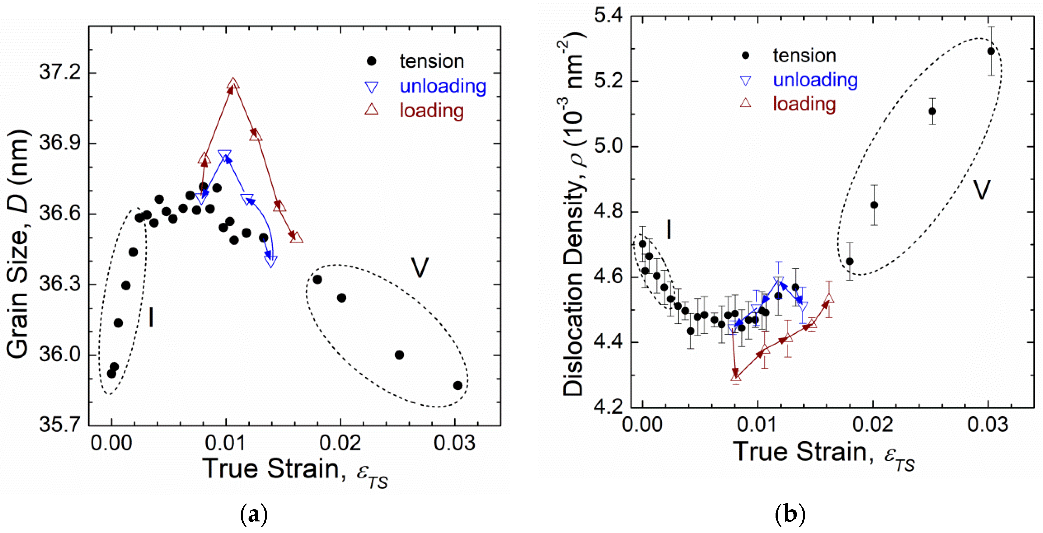
Grain growth and twinning mainly occur during the elastic deformation regime.
(2)
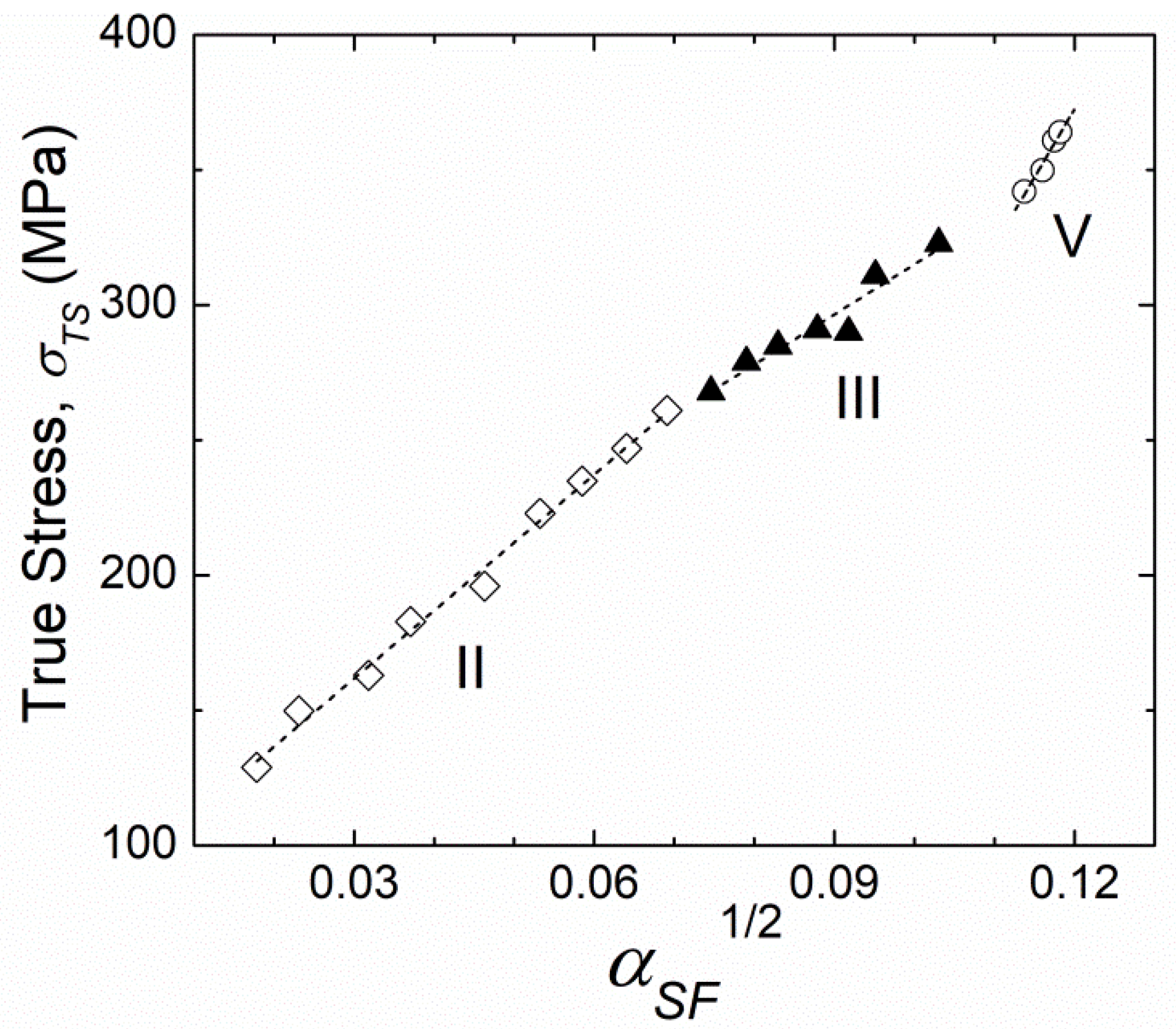
Detwinning and evolution of stacking faults occur in the early stage of plastic deformation. Stacking faults rather than dislocations can be stored during this deformation stage. Tensile stress correlates well with the probability of stacking faults in the early stage of plastic deformation. These behaviors support the partial-dislocation-mediated deformation mechanism previously proposed for nc metals.
(3)
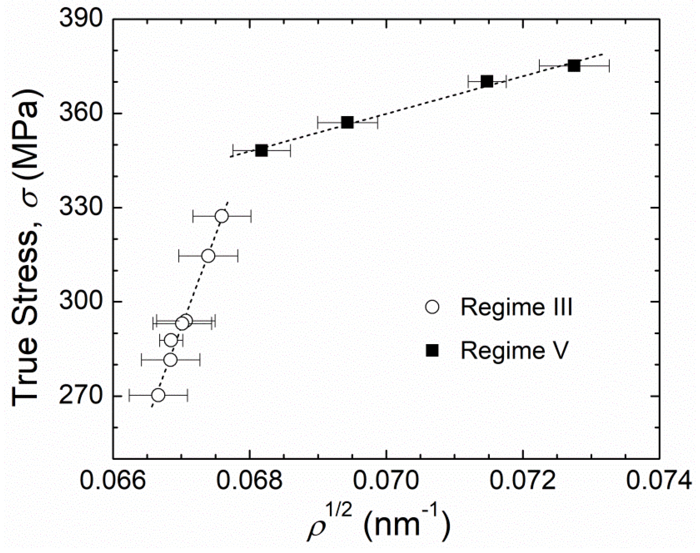
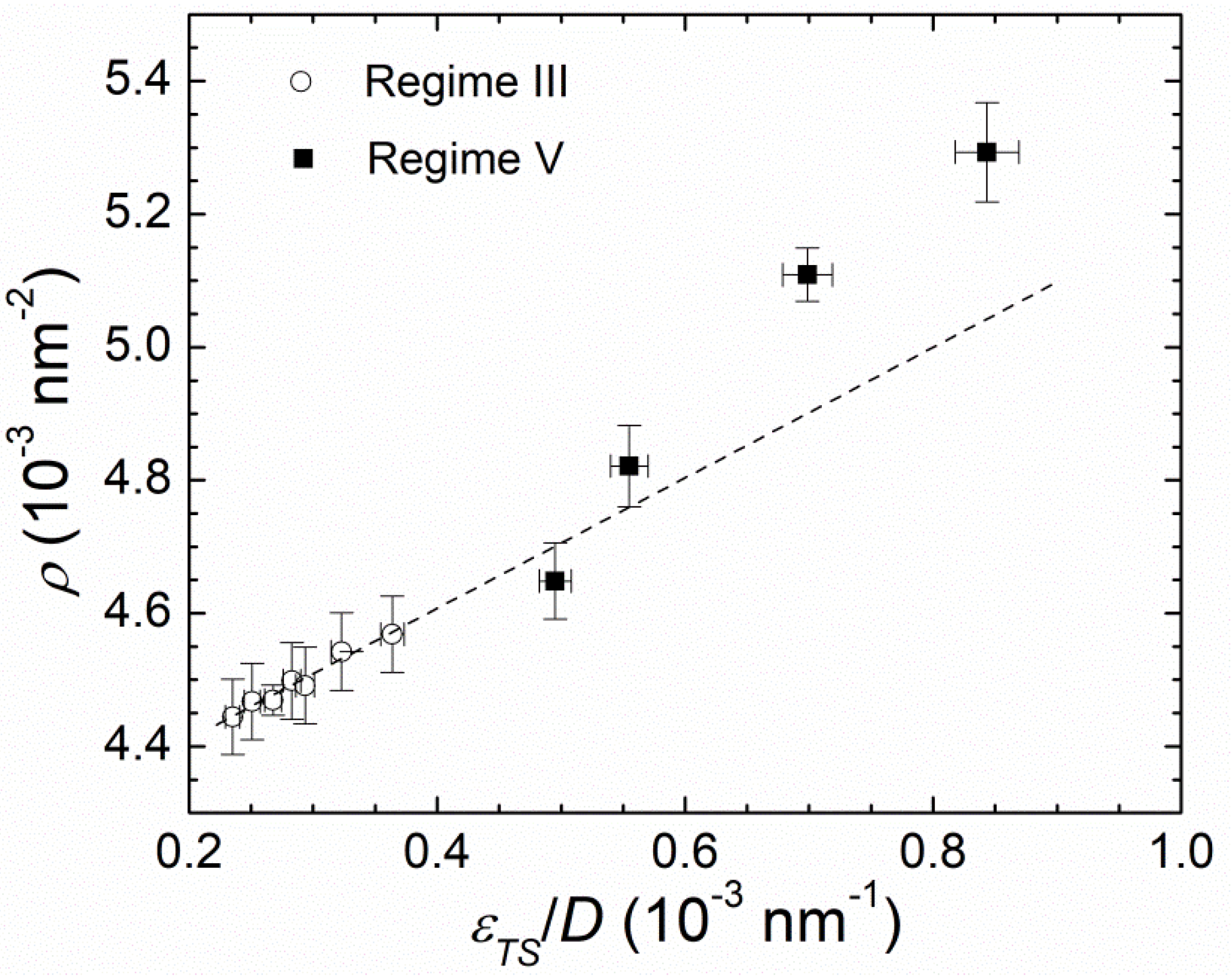
Grain shrinks whereas excess (or statistically stored) dislocations evolve in the final stage of plastically deformed nc-Ag. The relation between stress and total dislocation density follows the well-known strain-hardening theory developed for coarse-grained metals, suggesting that both statistically stored dislocations and geometrically necessary dislocations provide resistance for the plastic deformation of nc-Ag.
(4)
For our nc-Ag tested in a simple tension mode at a constant temperature and strain rate, multiple mechanisms such as grain growth, grain shrinking, twinning, detwinning, stacking faults, and statistically stored dislocations evolve in the elastic and/or plastic deformation stages. However, resistance for the plastic deformation is mainly provided by stacking faults (in the early stage of plastic deformation) and dislocations (in the final stage of plastic deformation).

Author Contributions

Conceptualization and Methodology, B.S. and T.S.; software, B.S.; validation, B.S. and T.S.; formal analysis, T.S.; investigation, B.S. and T.S.; resources, B.S.; data curation, T.S.; writing—original draft preparation, B.S.; writing—review and editing, T.S.; visualization, B.S.; supervision and project administration, T.S.; funding acquisition, B.S. and T.S. All authors have read and agreed to the published version of the manuscript.

Funding

This research was funded by the National Natural Science Foundation of China, grant numbers 11935004 and 51971195, the Natural Science Foundation of Hebei Province, grant number E2019203465 and B2020203037, the Basic Research Project of Yanshan University, grant number 16LGY010, and the China Scholarship Council, grant number 201807815014.

Acknowledgments

Authors of this article would like to acknowledge the US DOE for the usage of the beamline resources as well as C. A. Aydiner and M. Tang for their assistance with in situ XRD test and TEM observation, respectively.

Conflicts of Interest

The authors declare no conflict of interest.

References

  1. Meyers, M.A.; Mishra, A.; Benson, D.J. Mechanical properties of nanocrystalline materials. Prog. Mater. Sci. 2006, 51, 427–556. [Google Scholar] [CrossRef]
  2. Zhu, Y.T.; Liao, X.Z.; Wu, X.L. Deformation twinning in nanocrystalline materials. Prog. Mater. Sci. 2012, 57, 1–62. [Google Scholar] [CrossRef] [Green Version]
  3. Glezer, A.M.; Kozlov, E.; Koneva, N.A.; Popova, N.A.; Kurzina, I.A. Plastic Deformation of Nanostructured Materials; CRC Press: Boca Raton, FL, USA, 2017. [Google Scholar]
  4. Shen, T.D.; Schwarz, R.B.; Feng, S.; Swadener, J.G.; Huang, J.Y.; Tang, M.; Zhang, J.; Vogel, S.C.; Zhao, Y. Effect of solute segregation on the strength of nanocrystalline alloys: Inverse Hall-Petch relation. Acta Mater. 2007, 55, 5007–5013. [Google Scholar] [CrossRef]
  5. Ozerinc, S.; Tai, K.; Vo, N.Q.; Bellon, P.; Averback, R.S.; King, W.P. Grain boundary doping strengthens nanocrystalline copper alloys. Scr. Mater. 2012, 67, 720–723. [Google Scholar] [CrossRef]
  6. Abramova, M.M.; Enikeev, N.A.; Valiev, R.Z.; Etienne, A.; Radiguet, B.; Ivanisenko, Y.; Sauvage, X. Grain boundary segregation induced strengthening of an ultrafine-grained austenitic stainless steel. Mater. Lett. 2014, 136, 349–352. [Google Scholar] [CrossRef]
  7. Shen, T.D.; Xin, S.W.; Sun, B.R. Influence of annealing on the mechanical property of iron- and nickel-based nanocrystalline alloys. Mater. Sci. Eng. A 2015, 627, 139–144. [Google Scholar] [CrossRef]
  8. Liu, P.; Mao, S.C.; Wang, L.H.; Han, X.D.; Zhang, Z. Direct dynamic atomic mechanisms of strain-induced grain rotation in nanocrystalline, textured, columnar-structured thin gold films. Scr. Mater. 2011, 64, 343–346. [Google Scholar] [CrossRef]
  9. Kobler, A.; Kashiwar, A.; Hahn, H.; Kübel, C. Combination of in situ straining and ACOMTEM: A novel method for analysis of plastic deformation of nanocrystalline metals. Ultramicroscopy 2013, 128, 68–81. [Google Scholar] [CrossRef]
  10. Wang, L.; Teng, J.; Liu, P.; Hirata, A.; Ma, E.; Zhang, Z.; Chen, M.; Han, X. Grain rotation mediated by grain boundary dislocations in nanocrystalline platinum. Nat. Commun. 2014, 5, 4402. [Google Scholar] [CrossRef]
  11. Lohmiller, J.; Baumbusch, R.; Kraft, O.; Gruber, P.A. Differentiation of deformation modes in nanocrystalline Pd films inferred from peak asymmetry evolution using in situ x-ray diffraction. Phys. Rev. Lett. 2013, 110, 066101. [Google Scholar] [CrossRef]
  12. Wang, L.; Xin, T.; Kong, D.; Shu, X.; Chen, Y.; Zhou, H.; Teng, J.; Zhang, Z.; Zhou, J.; Han, X. In Situ observation of stress induced grain boundary migration in nanocrystalline gold. Scr. Mater. 2017, 134, 95–99. [Google Scholar] [CrossRef]
  13. Li, B.Q.; Sui, M.L.; Mao, S.X. Pseudoelastic stacking fault and deformation twinning in nanocrystalline Ni. Appl. Phys. Lett. 2010, 97, 241912. [Google Scholar] [CrossRef]
  14. Li, B.Q.; Li, B.; Wang, Y.B.; Sui, M.L.; Ma, E. Twinning mechanism via synchronized activation of partial dislocations in face-centered-cubic materials. Scr. Mater. 2011, 64, 852–855. [Google Scholar] [CrossRef]
  15. Kobler, A.; Lohmiller, J.; Schäfer, J.; Kerber, M.; Castrup, A.; Kashiwar, A.; Gruber, P.A.; Albe, K.; Hahn, H.; Kübel, C. Deformation-induced grain growth and twinning in nanocrystalline palladium thin films. Beilstein J. Nanotech. 2013, 4, 554–566. [Google Scholar] [CrossRef] [Green Version]
  16. Van Petegem, S.; Li, L.; Anderson, P.M.; Van Swygenhoven, H. Deformation mechanisms in nanocrystalline metals: Insights from in-situ diffraction and crystal plasticity modelling. Thin Solid Film 2013, 530, 20–24. [Google Scholar] [CrossRef]
  17. Wang, L.; Zhang, Z.; Ma, E.; Han, X.D. Transmission electron microscopy observations of dislocation annihilation and storage in nanograins. Appl. Phys. Lett. 2011, 98, 051905. [Google Scholar] [CrossRef]
  18. Adachi, H.; Karamatsu, Y.; Nakayama, S.; Miyazawa, T.; Sato, M.; Yamasaki, T. Elastic and plastic deformation behavior studied by in-situ synchrotron X-ray diffraction in nanocrystalline nickel. Mater. Trans. 2016, 57, 1447–1453. [Google Scholar] [CrossRef] [Green Version]
  19. Wang, L.; Han, X.; Liu, P.; Yue, Y.; Zhang, Z.; Ma, E. In Situ observation of dislocation behavior in nanometer grains. Phys. Rev. Lett. 2010, 105, 135501. [Google Scholar] [CrossRef] [Green Version]
  20. Sun, Z.; Van Petegem, S.; Cervellino, A.; Durst, K.; Blume, W.; Van Swygenhovena, H. Dynamic recovery in nanocrystalline Ni. Acta Mater. 2015, 91, 91–100. [Google Scholar] [CrossRef]
  21. Sarkar, R.; Rentenberger, C.; Rajagopalan, J. Electron beam induced artifacts during in situ TEM deformation of nanostructured metals. Sci. Rep. 2015, 5, 16345. [Google Scholar] [CrossRef] [Green Version]
  22. Zhang, X.H.; Wang, H.; Kassem, M.; Narayan, J.; Koch, C.C. Preparation of bulk ultrafine-grained and nanostructured Zn, Al and their alloys by in situ consolidation of powders during mechanical attrition. Scr. Mater. 2002, 46, 661–665. [Google Scholar] [CrossRef]
  23. Ribarik, G.; Ungar, T.; Gubicza, J. MWP-fit: A program for multiple whole-profile fitting of diffraction peak profiles by ab initio theoretical functions. Appl. Cryst. 2001, 34, 669–676. [Google Scholar] [CrossRef] [Green Version]
  24. Warren, B.E.; Averbach, B.L. The separation of cold-work distortion and particle size broadening in x-ray patterns. J. Appl. Phys. 1952, 23, 497. [Google Scholar] [CrossRef]
  25. Gallagher, P.C.J. The influence of alloying, temperature, and related effects on the stacking fault energy. Metall. Trans. 1970, 1, 2429–2461. [Google Scholar]
  26. Paterson, M.S. X-ray diffraction by face-centered cubic crystals with deformation faults. J. Appl. Phys. 1952, 23, 805–811. [Google Scholar] [CrossRef]
  27. Wagner, C.N.J. Stacking faults by low-temperature cold work in copper and alpha brass. Acta Met. 1957, 5, 427–434. [Google Scholar] [CrossRef]
  28. Warren, B.E.; Warekois, E.P. Stacking faults in cold worked alpha-brass. Acta Met. 1955, 3, 473–479. [Google Scholar] [CrossRef]
  29. Wagner, C.N.J. X-ray study of low-temperature cold work in silver and aluminum. Acta Met. 1957, 5, 477–482. [Google Scholar] [CrossRef]
  30. Cohen, J.B.; Wagner, C.N.J. Determination of twin fault probabilities from the diffraction patterns of fcc metals and alloys. J. Appl. Phys. 1962, 33, 2073–2077. [Google Scholar] [CrossRef]
  31. Carreker, R.P. Tensile deformation of silver as a function of temperature, strain rate, and grain size. JOM 1957, 9, 112–115. [Google Scholar] [CrossRef]
  32. Smithells, C.J. Metals Reference Book, 5th ed.; Butterworth & Co. Ltd.: London, UK, 1976; p. 975. [Google Scholar]
  33. Shen, T.D.; Koch, C.C.; Tsui, T.Y.; Pharr, G.M. On the elastic moduli of nanocrystalline Fe, Cu, Ni, and Cu–Ni alloys prepared by mechanical milling/ alloying. J. Mater. Res. 1995, 10, 2892–2896. [Google Scholar] [CrossRef]
  34. Lord, J.D.; Morrell, R.M. Elastic modulus measurement-obtaining reliable data from the tensile test. Metrologia 2010, 47, S41–S49. [Google Scholar] [CrossRef]
  35. Bailey, J.E.; Hirsch, P.B. The dislocation distribution, flow stress, and stored energy in cold-worked polycrystalline silver. Philos. Mag. 1960, 5, 485–497. [Google Scholar] [CrossRef]
  36. Ashby, M.F. The deformation of plastically non-homogeneous materials. Philos. Mag. 1970, 21, 399–424. [Google Scholar] [CrossRef]
  37. Adler, R.P.I.; Wagner, C.N.J. X-ray diffraction study of the effects of solutes on the occurrence of stacking faults in silver-base alloys. J. Appl. Phys. 1962, 33, 3451–3458. [Google Scholar] [CrossRef]
  38. Fan, G.J.; Wang, Y.D.; Fu, L.F.; Choo, H.; Liaw, P.K.; Ren, Y.; Browning, N.D. Orientation-dependent grain growth in a bulk nanocrystalline alloy during the uniaxial compressive deformation. Appl. Phys. Lett. 2006, 88, 171914. [Google Scholar] [CrossRef]
  39. Fan, G.J.; Fu, L.F.; Qiao, D.C. Grain growth in a bulk nanocrystalline Co alloy during tensile plastic deformation. Scr. Mater. 2006, 54, 2137–2141. [Google Scholar] [CrossRef]
  40. Fan, G.J.; Fu, L.F.; Choo, H.; Liaw, P.K.; Browning, N.D. Uniaxial tensile plastic deformation and grain growth of bulk nanocrystalline alloys. Acta Mater. 2006, 54, 4781–4792. [Google Scholar] [CrossRef]
  41. Gai, P.L.; Zhang, K.; Weertman, J. Electron microscopy study of nanocrystalline copper deformed by a microhardness indenter. Scr. Mater. 2007, 56, 25–28. [Google Scholar] [CrossRef]
  42. Jin, M.; Minor, A.M.; Stach, E.A.; Morris, J.W., Jr. Direct observation of deformation-induced grain growth during the nanoindentation of ultrafine-grained Al at room temperature. Acta Mater. 2004, 52, 5381–5387. [Google Scholar] [CrossRef]
  43. Legros, M.; Gianola, D.S.; Hemker, K.J. In Situ TEM observations of fast grain-boundary motion in stressed nanocrystalline aluminum films. Acta Mater. 2008, 56, 3380–3393. [Google Scholar] [CrossRef]
  44. Liao, X.Z.; Kilmametov, A.R.; Valiev, R.Z.; Gao, H.; Li, X.; Mukherjee, A.K.; Bingert, J.F.; Zhu, Y.T. High-pressure torsion-induced grain growth in electrodeposited nanocrystalline Ni. Appl. Phys. Lett. 2006, 88, 021909. [Google Scholar] [CrossRef]
  45. Wang, Y.B.; Li, B.Q.; Sui, M.L.; Mao, S.X. Deformation-induced grain rotation and growth in nanocrystalline Ni. Appl. Phys. Lett. 2008, 92, 011903. [Google Scholar] [CrossRef]
  46. Wang, Y.B.; Ho, J.C.; Liao, X.Z.; Li, H.Q.; Ringer, S.P.; Zhu, Y.T. Mechanism of grain growth during severe plastic deformation of a nanocrystalline Ni–Fe alloy. Appl. Phys. Lett. 2009, 94, 011908. [Google Scholar] [CrossRef] [Green Version]
  47. Zhang, K.; Weertman, J.R.; Eastman, J.A. Rapid stress-driven grain coarsening in nanocrystalline Cu at ambient and cryogenic temperatures. Appl. Phys. Lett. 2005, 87, 061921. [Google Scholar] [CrossRef]
  48. Gianola, D.S.; Petegem, S.V.; Legros, M.; Brandstetter, S.; Swygenhoven, H.V.; Hemker, K.J. Stress-assisted discontinuous grain growth and its effect on the deformation behavior of nanocrystalline aluminum thin films. Acta Mater. 2006, 54, 2253–2263. [Google Scholar] [CrossRef]
  49. Haslam, A.J.; Phillpot, S.R.; Wolf, D.; Moldovan, D.; Gleiter, H. Mechanisms of grain growth in nanocrystalline fcc metals by molecular-dynamics simulation. Mater. Sci. Eng. A 2001, 318, 293–312. [Google Scholar] [CrossRef]
  50. Xu, X.; Zhu, Y.T.; Chen, M.W.; Ma, E. Twinning and stacking fault formation during tensile deformation of nanocrystalline Ni. Scr. Mater. 2006, 54, 1685–1690. [Google Scholar]
  51. Yamakov, V.; Wolf, D.; Phillpot, S.R.; Mukherjee, A.K.; Gleiter, H. Deformation-mechanism map for nanocrystalline metals by molecular-dynamics simulation. Nat. Mater. 2004, 3, 43–47. [Google Scholar] [CrossRef]
  52. Liao, X.Z.; Zhao, Y.H.; Srinivasan, S.G.; Zhu, Y.T.; Valiev, R.Z.; Gunderov, D.V. Deformation twinning in nanocrystalline copper at room temperature and low strain rate. Appl. Phys. Lett. 2004, 84, 592–594. [Google Scholar] [CrossRef] [Green Version]
  53. Shan, Z.; Stach, E.A.; Wiezorek, J.M.K.; Knapp, J.A.; Follstaedt, D.M.; Mao, S.X. Grain boundary-mediated plasticity in nanocrystalline nickel. Science 2004, 305, 654–657. [Google Scholar] [CrossRef] [PubMed] [Green Version]
  54. Shen, T.D.; Koch, C.C.; McCormick, T.L.; Nemanich, R.J.; Huangv, J.Y.; Huang, J.G. The structure and properties of amorphous/nanocrystallite silicon produced by ball milling. J. Mater. Res. 1995, 10, 139–148. [Google Scholar] [CrossRef]
Figure 1. TEM image of as-prepared nc-Ag.
Metals 10 01635 g001
Figure 2. Dependence of macroscopic true stress ( σ T S ) and on true strain ( ε T S ) for bulk nc-Ag. Five dashed ovals representing the five deformation regimes (I to V).
Metals 10 01635 g002
Figure 3. FWHM for reflections (111) and (200) versus macroscopic true strain ( ε T S ) for bulk nc-Ag in tension and during unloading-loading.
Metals 10 01635 g003
Figure 4. Macroscopic stress ( σ T S ) plotted against microscopic lattice strain ( ε L S ) for reflections of (111), (200), (220) and (311) of nc-Ag. Horizontal dashed line: the macroscopic yield strength, 265 MPa, of nc-Ag. Solid lines: elastic stress-strain relations.
Metals 10 01635 g004
Figure 5. Grain size D (a) and dislocation density ρ (b) vs. macroscopic true strain ( ε T S ) for nc-Ag in tension and during unloading. Arrows: the sequences of unloading-loading in Regime IV. Dashed ovals: the elastic deformation stage (Regime I) and the final plastic deformation stage (Regime V).
Metals 10 01635 g005
Figure 6. True applied stress, σ T S , vs. the square root of dislocation density, ρ1/2, for nc-Ag plastically deformed in Regimes III and V, respectively. Dashed straight lines represent linearly fitted data.
Metals 10 01635 g006
Figure 7. Total dislocation density, ρ, vs. the ratio of true strain to grain size, ε T S /D, for nc-Ag deformed in Regimes III and V. Dashed straight lines represent linearly fitted data (open circles) within Regime III.
Metals 10 01635 g007
Figure 8. (a) Stacking fault probability α S F   and (b) twinning probability β vs. true strain ε T S for nc-Ag in tension and during unloading-loading. Arrows: the sequences of unloading-loading. Dashed ovals: the five deformation regimes (I to V).
Metals 10 01635 g008
Figure 9. True applied stress, σ T S , vs. the square root of stacking fault probability, α S F 1/2, for nc-Ag plastically deformed in Regimes II (◊), III (▲) and V (○), respectively. Dashed straight lines represent linearly fitted data.
Metals 10 01635 g009
Table 1. In situ studies and deformation mechanisms for nc Au, Ni, Pd and Pt metals.
In-Situ StudyMetalD (nm) 5Deformation MechanismsRef.
TEM 1Au20Grain rotation[8]
TEM & STEM 2Au37GB 6 motion;
Grain rotation;
Twinning/detwinning;
Grain growth (by 2.5%).
[9]
TEMAu18Cross-grain dislocations (D > 20 nm);
GB migration (D < 15 nm).
[12]
HRTEM 3Ni20Dislocation emission from GBs 7; Dislocation absorption by GBs;
Reversible twinning
[13]
HRTEMNi20Twinning[14]
SXRD 4Ni26Dislocation absorption by GBs[16]
SXRDNi35Competition between dislocation-based and GB-mediated mode[20]
SXRDNi52Dislocation accumulation[18]
SXRDPd28GB migration;
Grain growth (from 28 to 33 nm).
[11]
TEM & SXRDPd35Grain growth; Twinning/detwinning.[15]
TEMPt<10Full dislocations and the Lomer locks (D ~ 10 nm);
Partial dislocations and stacking faults (D < 10 nm).
[19]
TEMPt5–20Dislocations nucleation from GBs;
Storage of dislocations.
[17]
HRTEMPt<15Dislocation glide (D > 6 nm);
Grain rotation (D < 6 nm).
[10]
1 TEM = transmission electron microscope; 2 STEM = scanning transmission electron microscope; 3 HRTEM = high-resolution transmission electron microscope; 4 SXRD = synchrotron X-ray diffraction; 5 D = grain size; 6 GB = grain boundary; 7 GBs = grain boundaries.
Publisher’s Note: MDPI stays neutral with regard to jurisdictional claims in published maps and institutional affiliations.

