Article

Effect of TiN Spray Coating on Cracking Susceptibility and Energy Absorption in Laser Welding of Aluminum Alloys

1
Department of Materials Science and Engineering, Seoul National University, Seoul 08826, Korea
2
Advanced Functional Technology R&D Department, Korea Institute of Industrial Technology, Incheon 21999, Korea
*
Author to whom correspondence should be addressed.
Metals 2020, 10(12), 1657; https://doi.org/10.3390/met10121657
Submission received: 2 November 2020 / Revised: 6 December 2020 / Accepted: 7 December 2020 / Published: 9 December 2020

Abstract

:
This paper reports on the effect of a TiN spray coating on aluminum to improve laser welding issues such as cracking susceptibility and laser absorption. A self-restraint hot cracking test and bead on plate test were employed to compare the laser weldability between the base material and TiN-coated material. The welds with the TiN coating can be fully penetrated without cracks at lower power than the welds without the coating. TiN-incorporated metal matrix composites were formed on the top layer irradiated with the laser. The layer increases the laser absorption to transfer energy efficiently and strengthens it to withstand higher stresses and strains. In addition, the welding mechanism of this process is such that the ceramic coating layer blocks direct interaction between the laser and the metal melting pool, so that a keyhole is not formed, and welding is performed by heat conduction through the TiN ceramic medium.

1. Introduction

Aluminum alloys have a density equivalent to 34% of steel alloys, and alloys are an attractive material for lightweight automobiles and mileage improvement [1]. Welding of aluminum alloys is also required in the process of assembling the vehicle body. In particular, laser welding has high productivity, enabling work on a single side and excellent weldability with a narrow heat-affected zone and little thermal deformation [2]. Therefore, this process has a lot of potential to replace the existing welding processes in automobiles.
However, aluminum alloys have a low absorption rate in the infrared (IR) wavelength range of the laser [3]. When the laser beam is irradiated on the aluminum surface, most of the energy is scattered and reflected, and only a little bit of energy is absorbed and utilized for welding [4]. Thus, laser welding of aluminum alloys has a low energy efficiency and requires high-power laser equipment, which increases the production cost. Another issue in the laser welding of an aluminum alloy, is the high cracking susceptibility during solidification, which is called hot-cracking. The minor elements added to the aluminum alloy aid in the manufacturing process or improve the mechanical properties such as strength and toughness, but it increases the cracking susceptibility during rapid solidification. Defects such as the trapped pores formed by the collapse of unstable keyholes and spike-shaped humping beads promote cracks.
Various methods for evaluating the cracking susceptibility can be classified into two types, the self-restraint test and the externally restraint test [5]. In the former case, the weld geometry of the chosen specimen promotes cracks by stress formed from the specimen itself, and in the latter case by external loaded strain. The self-restraint test realistically simulates real welding conditions and evaluates for go or no-go [6]. For external restraint tests, the restraint level could be changed quantitatively, and the cracking susceptibility can be measured as a function of the restraint parameters using dedicated equipment. The self-restraint test method does not require expensive equipment, could evaluate cracking susceptibility through the relative comparison. This method has been widely applied for a long time as various methods, and tests using trapezoidal [7], fishbone-shaped [8,9], and simple rectangular specimens called free-edge test [10]. A numerical model using the free edge test has been researched to simulate the solidification crack behavior in the laser welding process of aluminum alloys [11].
Many studies have been researched to solve the issues above, such as the high cracking susceptibility and the low laser energy absorption of aluminum alloys. The absorption rate depends on various factors such as the material’s alloying element, band structure and resistivity, as well as the laser incident beam wavelength and surface conditions. The laser absorption was increased by modulating surface roughness where the laser irradiates, for example by grinding and sandblasting [1]. The surface modulation contributes to the rapid formation of a molten pool and keyhole. In addition, laser absorption has also been improved through using black paint or a carbon coating [12], a magnetic field [13], an activating ceramic flux [14], and anodizing to form Al2O3 films [15]. To reduce the cracking susceptibility, an auxiliary heat source or a defocusing beam was used to decrease the thermal shock that causes cracking [16]. In addition, beam modulation technology such as beam oscillation [17], adjustable ring mode laser [18], and pulse shaping [19] could suppress the crack initiation and propagation. Additionally, ceramic powder reduces cracking by limiting the surface tension gradient in the molten pool [20].
Ceramics are used for improving mechanical properties such as wear-resistance and hardness [21], and the ceramics which have low thermal conductivity and high transmission compared to metals are also used to improve laser absorption [1,22]. Some issues have been researched separately; however, in this study, the effect of ceramic coatings on cracking susceptibility and laser absorption is simultaneously evaluated by a free-edge test. In particular, TiN is one of the low emissivity (low-E) coating materials, which has a reflectance of less than 10% for the IR region [22]. In this paper, the effect of a TiN coating on Al 6061-T6, applied by spray coating, is evaluated. The process parameters required for full-penetration and required for crack propagation were analyzed.

2. Materials and Methods

The free-edge test used in this study is shown in Figure 1. The base material (BM) was a 1 mm-thick Al6061-T6 alloy and its composition—analyzed with an inductively coupled plasma-optical emission spectrometer (ICP-OES)—is shown in Table 1. The test workpiece having a size of 90 mm× 45 mm× 1 mm was used [10]. To arrest the propagation of cracks, an angle satisfying tanθ = 1/2 was given. The distance from the edge based on the welding starting point was divided into four levels: 0, 10, 20, and 30 mm. Laser power was measured from 400 W to 1800 W at 100 W intervals. Before determining the effect of the coating materials, the cracking susceptibility data of the BM itself was first evaluated. The database was established with four welding speeds of 5, 8, 10, and 12 mm/s.
The primary purpose of the study was to analyze the effect of TiN, and Al2O3, an oxide ceramic of aluminum, was additionally employed for comparison. Aerosol sprays for TiN coating (ZYP-053, ZYP coatings, Oak Ridge, TN, USA) and for Al2O3 coating (ZYP-004, ZYP coatings Oak Ridge, TN, USA) were used. The spray-coated specimen was carried out at a distance of 30 cm from the surface and the coating layer was controlled to be deposited to a thickness of 50 ± 10 μm, and then dried in air. In this condition, the coating layer is deposited at a thickness of 50 μm. Three samples of each condition were evaluated. The Al2O3 and TiN-coated BM were subjected to a self-restraint test by applying a scan speed of 12 mm/s and laser power from 400 W to 1800 W. The values of each process parameter are listed in Table 2. The laser was a disk laser (HLD 4002, Trumpf, Ditzingen, Germany) using a Yb:YAG source with 1030 nm of wavelength, and was transmitted through a 200 μm optical fiber and irradiated with a scanner-type laser head. The laser beam used a beam with a diameter of 0.6 mm at the focal point. The appearance of the specimens was measured through an optical microscope, and the cross-section was subjected to field emission scanning electron microscope (FE-SEM, Quanta200F, Thermo Fisher, Eindhoven, Netherlands) image analysis and energy dispersive X-ray spectroscopy (EDS, Genesis APEX2, AMETEK, Paoli, PA, USA) component analysis.

3. Results

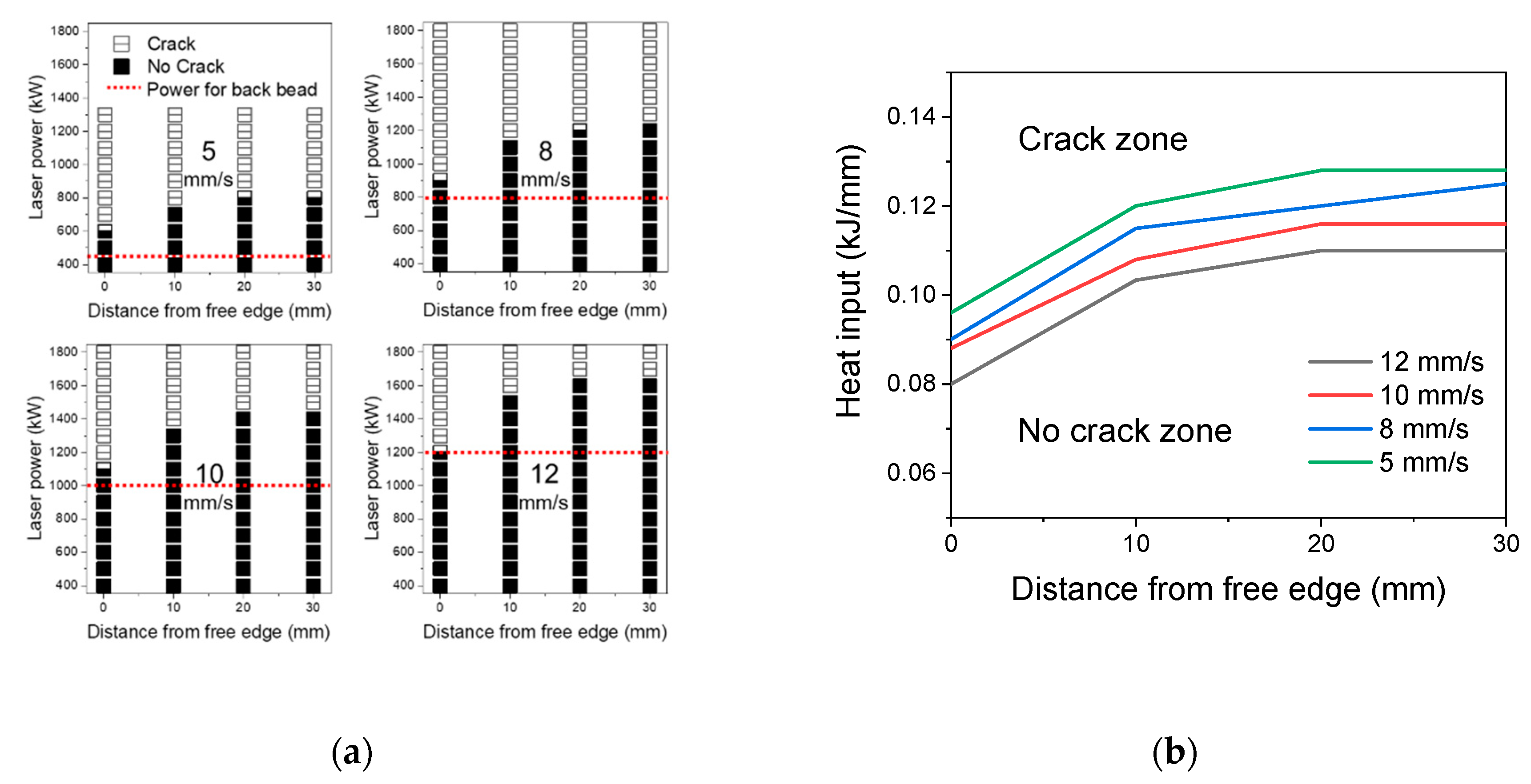
3.1. Cracking Susceptibility of Base Material by Free-Edge Test

Since the free-edge test is challenging to evaluate quantitative stress and strain, the test requires a database for the relative comparison of various laser welding conditions of the BM. Three samples were tested under the same conditions, and the conditions without cracks in all three samples are marked with a filled square in Figure 2. The condition where all cracks occurred in all three samples was marked with a centerline in the open square. A half-filled square indicated the conditions in which cracks were found in one or two out of three samples. The boundary line of the laser power where the back bead starts to occur is displayed in a red dotted line. When the starting position is changed, the probability of cracking is also different even under the same laser power and scan speed. The closer the starting position of the laser beam is to the edge, the greater the total deformation consisting of thermal deformation, elastic deformation, and plastic deformation. Thus, as the distance from the edge increases, the probability of cracking decreases (Figure 2).
As the laser welding speed increases, the laser power for occurring back beads (red dotted line) and cracks also increases. Since similar beads are formed under equal heat input per unit length, a high output is required to form back beads at the high speed. To compare the effect of scan speed as shown in Figure 2b, the boundary line where cracks occur is converted into heat input and marked. The line separates the crack zone where crack occurs and the no crack zone where crack did not occur in the condition. In the condition with high scan speed, the crack zone expanded, which means that the cracking susceptibility increases. The fast scan speed has a high strain rate because the strain is concentrated in a short time and tends to form an unstable molten pool. In addition, a fast solidification rate does not provide a sufficient volume of liquid metal between the grains at the final stage of solidification. Therefore, welding at a lower scan speed is better to prevent crack formation. In Figure 2b, the slope of the line decreases as the distance from the edge (X) increases. As the distance from the edge increases, the strain applied to the specimen exponentially decreases [10]. Compared to the condition of X value of 20 mm, the increment is little or converges at 30 mm. Thus, the welds at a distance of 30 mm or more are hardly affected by the free edge.

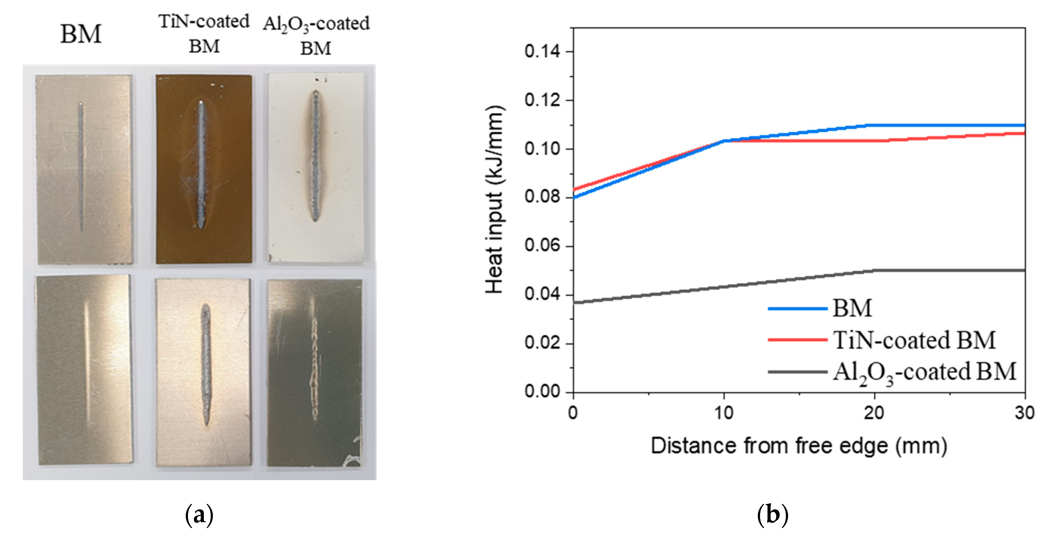
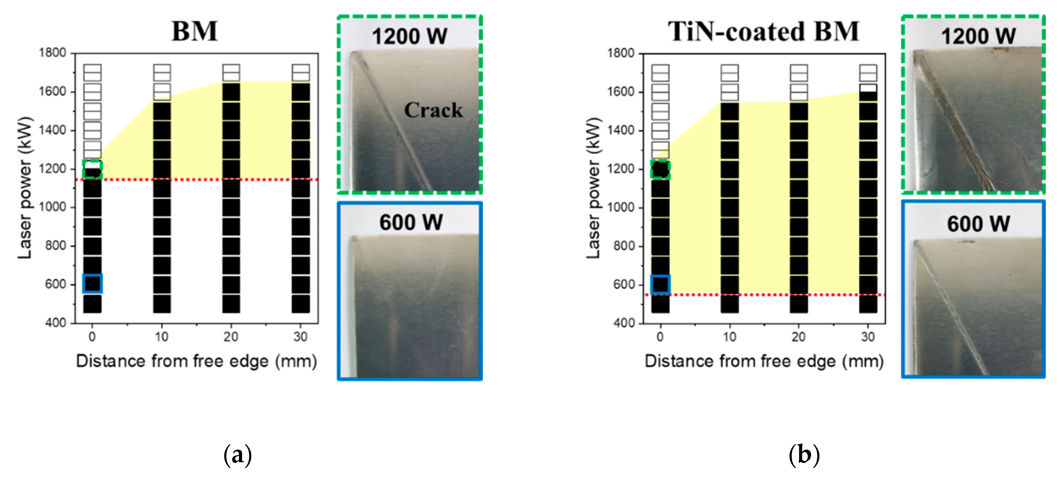
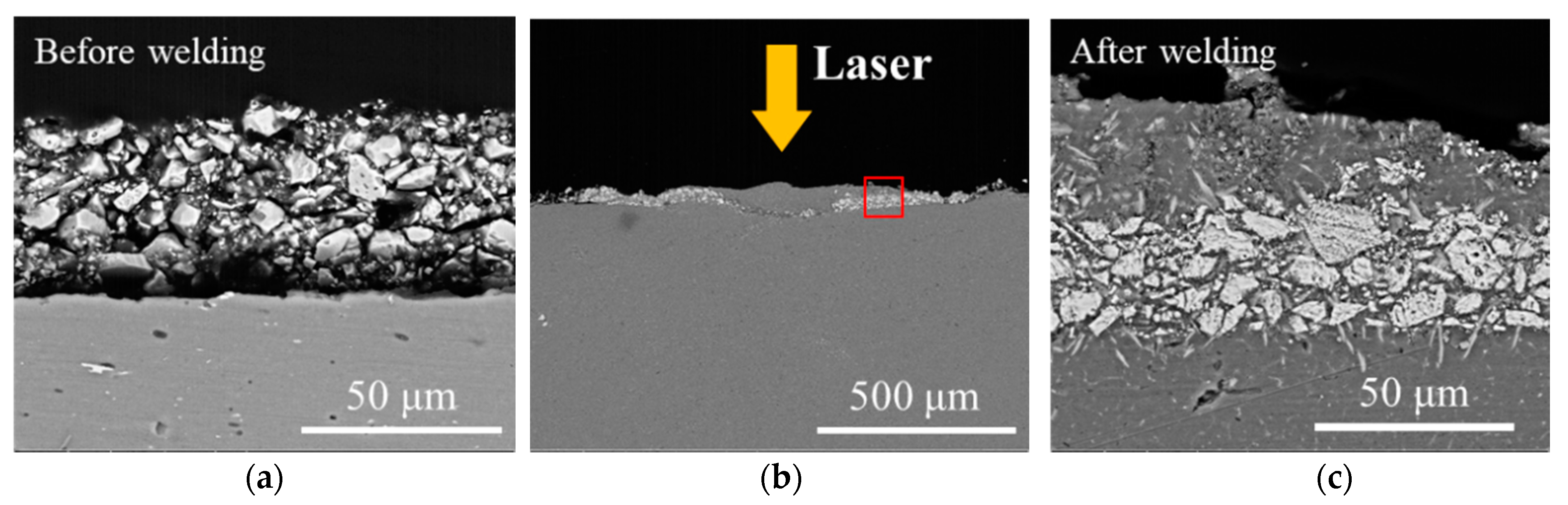
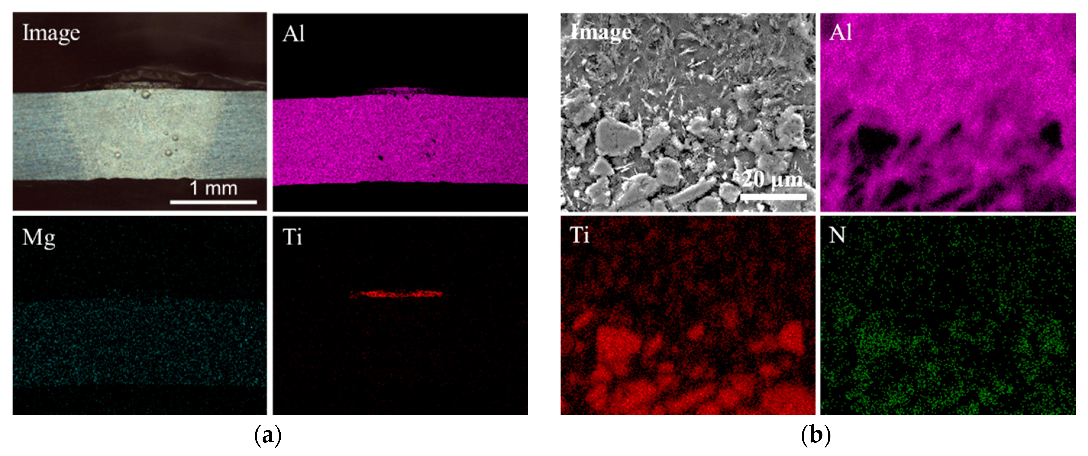
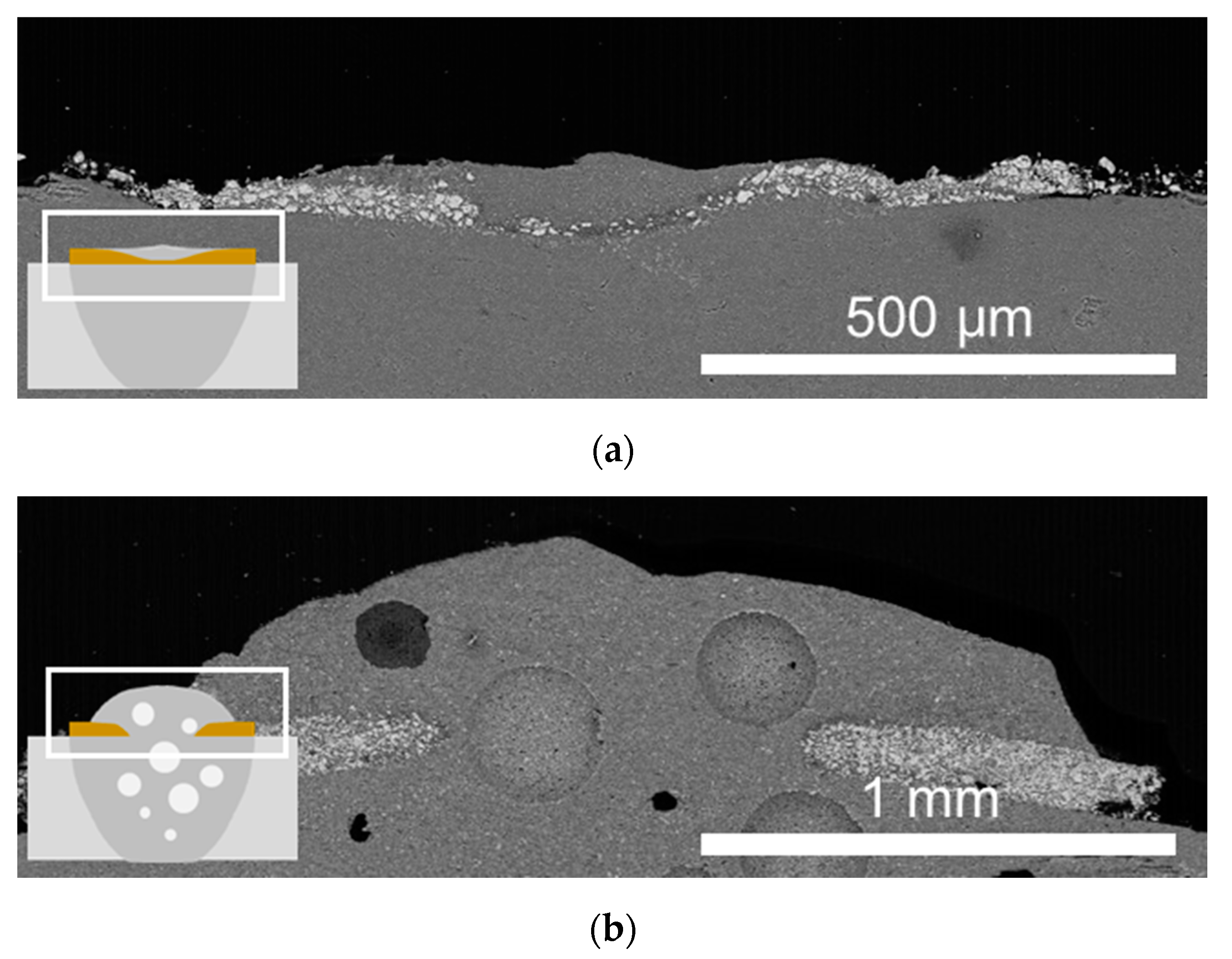
3.2. Effect of Tin Coating on Laser Weldability (Cracking Susceptibility, Laser Absorption)

After ceramic spray coating, the TiN coating layer had a brown color, and the Al2O3 coating had a white color (Figure 3a). Bead on plate (BOP) welding was performed under the same conditions having a laser power of 1 kW and a welding speed of 10 mm/s. In the backside of the BM without coating, only traces of heat deformation were visible, and no trace of melting was observed. The welds of Al2O3-coated BM had an unstable and discontinuous back bead, while the welds of TiN-coated BM had a wide and continuous back bead. When ceramic materials such as TiN and Al2O3 are coated, heat is more effectively transferred, even though the overall thickness increases owing to the coating layer. In other words, the ceramic coating forms a larger molten pool than the BM and could create full penetration at the lower power. TiN-coated BM absorbs more energy efficiently than Al2O3-coated BM because more stable back beads appear.
A free-edge test used in the previous section was performed to analyze the effect of the coating on cracking susceptibility. The result of these samples is shown in Figure 2b, the boundary at which crack zone and no crack zone is divided, and the vertical axis is displayed by converting laser power and scan speed into heat input (Figure 3b). The Al2O3-coated BM showed cracks in the beads when a heat input of 0.04 to 0.05 kJ/mm was applied. The Al2O3 coating could achieve full penetration with a lower heat input than the BM, but it also increased the cracking susceptibility.
On the other hand, in TiN-coated BM, the cracking susceptibility is almost the same as that of the BM. When X is 0 mm, the cracks were found under the heat input of 0.08 kJ/mm or more. Since the TiN coating increases the energy efficiency, the increased effective heat input creates a broader and deeper weld pool than the uncoated BM (Figure 3a). In Figure 3b, BM and TiN-coated BM begin to crack at similar heat input levels, but TiN-coated BM has a much lower cracking susceptibility than the BM when considering the size of bead formed. Therefore, the TiN coating increases the energy efficiency of a laser heat source and reduces the cracking susceptibility.
Figure 4 shows the results of the free edge test of the uncoated BM and TiN-coated BM, and the back bead images under the two representative conditions are shown on the right of each graph. A weldable process window for fabricating sound beads could be determined from the power at which the back bead starts to occur, indicated by the red dotted line, to the power at which cracks do not occur. Images with solid blue and dashed green lines show the back bead of a sample welded with laser powers of 600 W and 1200 W, respectively. The BM has no weldable condition at a distance from the edge of 0 mm (Figure 4a). When the back bead starts to occur at the laser power of 1200 W, the crack also coincides. Under the laser power of 600 W, the BM had no back bead. On the other hand, the back bead was visible in the TiN-coated BM, and a sound bead was formed without a crack from 600 W to 1200 W. Even the width of the back bead made of the BM with the laser power of 1200 W is similar to that of 600 W for TiN-coated BM. In Figure 4, the weldable process window is shown in shades of yellow. When the distance from the edge is 20 mm, the area for the weldable process window of the BM corresponds to 1200–1600 W, whereas TiN-coated BM represents an area of 600–1500 W. The TiN coating not only reduces the required laser power by about half but also doubles the weldable areas. In other words, the TiN coating significantly increases the thermal efficiency and helps to expand the appropriate process conditions. Put another way, the TiN coating of the aluminum increases the laser absorption, enabling back bead formation at a lower power than BM. In addition, this lowers the cracking susceptibility; thus, cracking does not occur even on an expansive back bead. This lowers the weldable laser power and helps to expand the process window without defects.
In the as-sprayed sample, TiN particles with a size of several μm were aggregated and deposited at a thickness of about 50 μm (Figure 5a). After laser welding, the particles did not disappear in the laser-irradiated area, and particles remained at the top. The spray-deposited particles that were not affected by the laser were removed during the polishing process. The central part that irradiated the laser beam with a Gaussian distribution is partially dissolved, but the layer with light gray particles layer remains (Figure 5b). Figure 5c is an enlarged image of the red box in Figure 5b. Newly formed needle-shaped particles around the existing irregular particles are observed, which are estimated to be formed during rapid solidification after melting by the laser. The metal matrix composite (MMC) was formed by the interaction between TiN and the BM by the laser heat source. Figure 6 shows the results of the EDS mapping analysis of the cross-section of BOP welding with the TiN-coated BM. Only the top three most clearly measured elements are displayed. In the low magnification, Al, Mg, and Ti were clearly observed, and in the high magnification image of the top part, Al, Ti, and N were clearly observed. Al and Mg elements exist, but no difference in composition between the melted weld metal and the un-melted BM was observed (Figure 6a). One distinct feature is that the Ti and N elements were densely distributed in the top part where the laser is irradiated (Figure 6b). Since the N Kα peak at 0.39 eV and the Ti Lα peak at 0.45 keV overlap in the EDS analysis, the N Kα detection image includes Ti Lα [23]. However, TiN is very stable due to high affinity between Ti and N, and the raw material contains nitrogen in the form of TiN. Therefore, the particles in Figure 7b could be regarded as TiN. A metal layer whose main component is Al exists above the TiN layer. BM moves up between TiN particles, occupying the place where TiN disappeared.
The MMC layer formed on the top part blocks the laser energy from directly interacting with the molten pool. The main mechanism in this process is not keyhole mode welding, which is formed by the evaporation of molten pool, but thermal conduction through the ceramic material as a medium. In addition, since laser welding is single-sided welding process, the weld bead is asymmetric, and a nail-shaped weld metal is formed. The feature could increase the stress and strain during the solidification process. However, through heat conduction by the ceramic, the back bead is formed with a relatively wide and less asymmetric shape. For this reason, TiN coatings on the aluminum could reduce cracking susceptibility.
Figure 7 shows two kinds of welds with the same heat input condition, but the scan speed and laser power are each times two. Since the energy distribution of the used laser shows a Gaussian function, the energy is concentrated at the center. More dissolution of MMC occurs in the central part than the side. The molten layer is solidified as the layer rises due to surface tension in the thinned or disappeared MMC layer region. Since TiN plays a crucial role in absorbing laser energy and transferring thermal energy, the dissolution of the TiN particles reduces the thermal efficiency. In the condition of fast scan speed and high laser power, as shown in Figure 7b, even if the thickness of the powder layer is doubled, the powder layer is dissolved or pushed away by the laser energy. In this case, humping beads and trapped pores are generated due to the vaporization of the molten pool, which is observed in typical Al laser welding. Laser welding using a TiN coating layer is key to suppressing keyholes and expanding the welding by conduction mode to enable low power welding without defects. If a faster processing speed is required, a deposition process capable of forming a dense TiN layer may be an alternative.

4. Conclusions

As aluminum alloys applied to vehicle bodies become more common, a laser welding technology for the alloys is required. The effect of TiN coating on Al 6061-T6 was evaluated to reduce the high temperature cracking susceptibility and increase the low laser absorption in the laser wavelength. Through a free-edge test—a kind of self-restraint hot cracking test—the database of BM and TiN-coated BM was constructed and compared. TiN-coated BM efficiently transferred the laser energy, and full penetration was possible with less than half of the heat input compared to the base material. In addition, after laser welding, the TiN-incorporated metal matrix composites layer was fabricated on the top, and the back bead was formed in a broader manner and without cracks, when compared to the case without coating. This layer acts as a medium of laser absorption and mitigates the direct interaction between the laser energy and the molten pool, suppressing the defects and increasing the energy efficiency. Because of the effects of the TiN coating, the cracking susceptibility was reduced in the free edge test, and the TiN coating significantly extended the process range where welding is suitable. The TiN ceramic coating enables low-power laser welding and reduces the cracking susceptibility, which is expected as a novel technology for aluminum laser welding.

Author Contributions

Investigation, S.N.; methodology, S.N. and Y.-M.K.; supervision, I.-H.J. and Y.-M.K.; writing—original draft, S.N.; writing—review and editing, Y.-M.K. All authors have read and agreed to the published version of the manuscript.

Funding

This research was funded by the world class 300 project of Ministry of Trade, Industry and Energy and Ministry of SMEs (Small and Medium-sized Enterprises) and Startups.

Acknowledgments

This research was supported by the project of “Development of deformation control smart manufacturing technology for realizing digital cockpit of ultra-lightweight cowl cross” project of the technology development support of the world class 300 project of Ministry of Trade, Industry and Energy and Ministry of SMEs (Small and Medium-sized Enterprises) and Startups.

Conflicts of Interest

The authors declare no conflict of interest.

References

  1. Quazi, M.M.; Fazal, M.A.; Haseeb, A.S.M.A.; Yusof, F.; Masjuki, H.H.; Arslan, A. Laser-based Surface Modifications of Aluminum and its Alloys. Crit. Rev. Solid State Mater. Sci. 2015, 41, 106–131. [Google Scholar] [CrossRef]
  2. Hong, K.-M.; Shin, Y.C. Prospects of laser welding technology in the automotive industry: A review. J. Mater. Process. Technol. 2017, 245, 46–69. [Google Scholar] [CrossRef]
  3. Li, L. The advances and characteristics of high-power diode laser materials processing. Opt. Lasers Eng. 2000, 34, 231–253. [Google Scholar] [CrossRef]
  4. Martukanitz, R.P.; Altshuller, B. Laser beam welding of aluminum alloy 5754-O using a 3 kW Nd:YAG laser and fiber optic beam delivery. In Proceedings of the International Congress on Applications of Lasers & Electro-Optics, Orlando, FL, USA, 2–5 November 2009; pp. 39–44. [Google Scholar] [CrossRef]
  5. Kannengiesser, T.; Boellinghaus, T. Hot cracking tests—An overview of present technologies and applications. Weld. World 2014, 58, 397–421. [Google Scholar] [CrossRef]
  6. Goodwin, G. Test methods for Evaluating Hot Cracking: Review and Perspective; Oak Ridge National Lab.: Oak Ridge, TN, USA, 1990. [Google Scholar]
  7. Wang, W.; Xiong, L.; Wang, D.; Ma, Q.; Hu, Y.; Hu, G.; Lei, Y. A New Test Method for Evaluation of Solidification Cracking Susceptibility of Stainless Steel during Laser Welding. Materials 2020, 13, 3178. [Google Scholar] [CrossRef]
  8. Gao, H.; Agarwal, G.; Amirthalingam, M.; Hermans, M.J.M.; Richardson, I.M. Investigation on hot cracking during laser welding by means of experimental and numerical methods. Weld. World 2017, 62, 71–78. [Google Scholar] [CrossRef] [Green Version]
  9. Matsuda, F.; Nakata, K. A New Test Specimen for Self-Restraint Solidification Crack Susceptibility Test of Electron-Beam Welding Bead: Fan-Shaped Cracking Test (Materials, Metallurgy & Weldability). Trans. JWRI 1982, 11, 87–94. [Google Scholar]
  10. Agarwal, G.; Gao, H.; Amirthalingam, M.; Hermans, M. Study of Solidification Cracking Susceptibility during Laser Welding in an Advanced High Strength Automotive Steel. Metals 2018, 8, 673. [Google Scholar] [CrossRef] [Green Version]
  11. Wang, X.; Lu, F.; Wang, H.-P.; Cui, H.; Tang, X.; Wu, Y. Mechanical constraint intensity effects on solidification cracking during laser welding of aluminum alloys. J. Mater. Process. Technol. 2015, 218, 62–70. [Google Scholar] [CrossRef]
  12. Kek, T.; Grum, J. Influence of the Graphite Absorber During Laser Surface Hardening. Stroj. Vestn. J. Mech. Eng. 2010, 56, 150–157. [Google Scholar]
  13. Chen, J.; Zhang, Q.; Yao, J. The effect of external applied electric field on the laser absorption of metal materials. Laser Technol. 2009, 33, 121–123. [Google Scholar]
  14. Qin, G.-L.; Wang, G.-G.; Zou, Z.-D. Effects of activating flux on CO2 laser welding process of 6013 Al alloy. Trans. Nonferr. Metal Soc. China 2012, 22, 23–29. [Google Scholar] [CrossRef]
  15. Yusof, F.; Yukio, M.; Yoshiharu, M.; Shukor, M.H.A. Effect of anodizing on pulsed Nd: YAG laser joining of polyethylene terephthalate (PET) and aluminium alloy (A5052). Mater. Des. 2012, 37, 410–415. [Google Scholar] [CrossRef]
  16. Punkari, A.; Weckman, D.C.; Kerr, H.W. Effects of magnesium content on dual beam Nd: YAG laser welding of Al—Mg alloys. Sci. Technol. Weld. Join. 2013, 8, 269–281. [Google Scholar] [CrossRef]
  17. Kang, M.; Han, H.N.; Kim, C. Microstructure and solidification crack susceptibility of Al 6014 molten alloy subjected to a spatially oscillated laser beam. Materials 2018, 11, 648. [Google Scholar] [CrossRef] [Green Version]
  18. Kang, M.; Kim, C. Evaluation of hot cracking susceptibility on laser welded aluminum alloy using coaxially arranged multiple-beam laser. J. Laser Appl. 2020, 32, 022072. [Google Scholar] [CrossRef]
  19. von Witzendorff, P.; Kaierle, S.; Suttmann, O.; Overmeyer, L. Using pulse shaping to control temporal strain development and solidification cracking in pulsed laser welding of 6082 aluminum alloys. J. Mater. Process. Technol. 2015, 225, 162–169. [Google Scholar] [CrossRef]
  20. Wang, M.; Li, Y.; Wang, Z.; Bao, E. Effect of rare earth elements on the thermal cracking resistance of high speed steel rolls. J. Rare Earths 2011, 29, 489–493. [Google Scholar] [CrossRef]
  21. D’Amato, C.; Buhagiar, J.; Betts, J.C. Tribological characteristics of an A356 aluminium alloy laser surface alloyed with nickel and Ni–Ti–C. Appl. Surf. Sci. 2014, 313, 720–729. [Google Scholar] [CrossRef]
  22. Zheng, P.; Zhao, G.; Zhang, T.; Wu, L.; Wang, J.; Han, G. Study of titanium nitride for low-e coating application. Chin. Sci. Bull. 2007, 52, 1860–1863. [Google Scholar] [CrossRef]
  23. Kurtoğlu, S.F.; Yağcı, M.B.; Uzun, A.; Ünal, U.; Canadinc, D. Enhancing biocompatibility of NiTi shape memory alloys by simple NH3 treatments. Appl. Surf. Sci. 2020, 146547. [Google Scholar] [CrossRef]
Figure 1. (a) Schematic diagram of free edge test and (b) image of a specimen after the test.
Metals 10 01657 g001
Figure 2. (a) Database of free edge test for base material (BM) under various welding conditions and (b) the graph showing relationship of heat input and welding speed on cracking susceptibility.
Metals 10 01657 g002
Figure 3. (a) Appearance of laser-welded samples using 10 mm/s of scan speed and 1 kW of laser power. The top and bottom images indicate the front bead and the back bead, respectively. (b) Free-edge test result showing the effect of coating materials.
Metals 10 01657 g003
Figure 4. Free edge test data using (a) BM and (b) TiN-coated BM. The photos representatively show the back bead tested under the same condition except for the power at 1200 W (above) and 600 W (below).
Metals 10 01657 g004
Figure 5. Images of TiN-coated BM (a) before laser welding and (b) and (c) after laser welding.
Metals 10 01657 g005
Figure 6. EDS mapping analysis of (a) the macro cross-section and (b) the top layer of laser-welded TiN-coated BM.
Metals 10 01657 g006
Figure 7. FE-SEM images show the laser-irradiated top part under process parameters of (a) 1 kW, 12 mm/s and (b) 2 kW, 24 mm/s. Insets on the left are a schematic view of the cross-section of the welds.
Metals 10 01657 g007
Table 1. Chemical composition (wt.%) of powder used in this study.
AlSiFeCuMnMgCrZnTiothers
Bal.0.660.40.240.130.90.180.070.050.02
Table 2. Process parameter values for free edge test.
ParameterValue
Distance from the free edge (X)0, 10, 20, 30 mm
Laser power400–1800 W (Interval: 100 W)
Laser speed5, 8, 10, 12 mm/s
Coating materialsNone, TiN, Al2O3
Welding angle (θ)26.6 (tanθ = 0.5)
Publisher’s Note: MDPI stays neutral with regard to jurisdictional claims in published maps and institutional affiliations.

