Article

The Influence of the Highly Concentrated Energy Treatments on the Structure and Properties of Medium Carbon Steel

by
Sergey N. Grigoriev
1,
Alexandr Yu. Ivannikov
2,*,
Maxim V. Prozhega
3,
Igor N. Zakharov
4,
Olga G. Kuznetsova
2 and
Alexandr. M. Levin
2
1
Chair of High-Efficiency Machining Technologies, Moscow State Technological University Stankin, Vadkovskiy Per. 3A, 127055 Moscow, Russia
2
Baikov Institute of Metallurgy and Material Science, Russian Academy of Sciences, 49, Leninsky Ave., 119334 Moscow, Russia
3
Mechanical Engineering Research Institute, Russian Academy of Sciences, 4, Maly Kharitonyevsky Pereulok, 101990 Moscow, Russia
4
Chair of Resistance of Materials, Volgograd State Technical University, 28, Lenin Ave., 400005 Volgograd, Russia
*
Author to whom correspondence should be addressed.
Metals 2020, 10(12), 1669; https://doi.org/10.3390/met10121669
Submission received: 30 October 2020 / Revised: 3 December 2020 / Accepted: 11 December 2020 / Published: 14 December 2020
(This article belongs to the Section Metal Casting, Forming and Heat Treatment)

Abstract

:
This paper describes the effects of combination of electromechanical and ultrasonic treatment on the wear and corrosion behavior of carbon steel AISI 1045. It is shown that the wear resistance of carbon steel AISI 1045 can be improved considerably by hardening the surface. Furthermore, the experimental work indicates that the corrosion rate of the surface decreased because of the combination of the treatments.

Graphical Abstract

1. Introduction

Enhancing the operational properties of products and components, which work in extreme conditions, is one of the most important problems to be solved by mechanical engineering. The quality of this group of products is largely determined by the quality of their surface. The existing traditional technological processes for surface finishing [1,2,3,4,5] do not satisfy the ever-changing requirements of the modern industry. For this reason, the field of the high energy methods for surface finishing offers a large pool of researches and developments [6,7,8,9,10,11,12].
Frequently, laser treatment [6,7], electron beam [8,9,10], and plasma arc [11,12,13] are used for surface hardening of steels, alloys, and coatings. The industry offers the wide choice of equipment for laser, electron, and plasma treatments, but this equipment is rather expensive. Another type of the high energy methods for surface finishing is ultrasonic treatment. The ultrasonic treatment is used for improving roughness of the surface and, to a lesser extent, for hardening the surface. In practice, ultrasonic equipment can be mounted on lathes, milling machines, and robotic systems for finishing treatment.
Combining thermo-straining methods may be a new way to improve stability of steel and alloy surfaces. Few scientific works describe various combinations of the highly concentrated energy treatments. Lesyk et al. [14] studied combined process of laser surface hardening and ultrasonic impact treatment. The combined treatment improved microgeometry of the surface of the AISI D2 tool steel, hardened the surface almost three times, and formed compressive residual stresses in the near-surface layers. Lv et al. [15] studied the effect of shot peening on fatigue resistance of laser-treated 20CrMnTi steel. It was shown that the combination of the treatments gave more effect on improving the fatigue and the wear resistance of the steel than the single treatment. A review of literature in the field of the combination of thermo-straining treatments showed that a limited number of studies had reported result. Thus, development of novel techniques is a topical task to improve wear resistance and corrosion resistance of surfaces.
As mentioned above, the expensive equipment is required for hardening the surfaces by means of the laser methods. There are alternative technologies, for example, electric contact surface hardening or electromechanical treatment. Qi et al. [16] studied electric contact surface hardening of ductile iron. It was shown that fatigue limit of ductile iron increased from 693 N/mm2 to 1054 N/mm2 after the treatment. Also, this process increased the surface hardness and formed residual compressive stress in the modified zone. In addition, the electric contact surface hardening was used for hardening the coatings [17,18,19]. Wang et al. [17] used the electric contact surface hardening to improve the adhesion strength of WC-Co coating with substrate from carbon steel. Wang et al. [15] used the electric contact surface hardening to improve the adhesion strength of stainless steel coating with substrate from carbon steel.
On the other hand, in the articles [20,21] the electromechanical treatment (EMT) was used for hardening of the coatings. This approach was based on the combination of pressure by means of the roller with Joule heating of the coating surface. Recently, Ivannikov et al. [22] showed that the EMT improved the wear resistance of the high speed steel coating and decreased the wear rate of the counterfaces.
It is noteworthy to mention that the temperature of the heating zone is measured differently during the laser hardening, the electric contact surface hardening, and the electromechanical treatment. During the laser hardening the direct temperature measurement of the heating zone can be studied by means of an optical pyrometer [23]. During the electric contact surface hardening and the electromechanical treatment the heat zone is closed by the treatment roller, so the direct temperature of the contact zone cannot be measured. For this reason, Qi et al. [24] used theoretical and experimental analysis of the electric contact surface hardening of ductile iron. The temperature field of the surface was simulated using ANSYS software. It was shown that the temperature of the contact zone was above 1400 °C. The simulated results were proven by experimental data. The numerical modelling of the EMT process was made in the study of Ivannikov et al. [25]. The cooling rate in the contact zone was calculated depending on the current density, it was more than 104 K/s. The formation of the nanostructured crystal phases verified the numerically simulated high cooling rate during the EMT process.
Bearing in mind that the surface of the steel can be treated by means of the electromechanical treatment with high cooling rate, we can assume this method for the surface treatment of the AISI 1045 steel. In practice, the EMT can be realized on the same machine as the ultrasonic treatment (UT). Thus, these methods can be combined for the surface treatment of the steels and alloys.
Recently, Lesyk et al. [26] studied the combined process of the laser surface hardening and the ultrasonic impact treatment. The highest corrosion resistance enhancement was observed after the combined treatment.
The purpose of this work is to estimate the influence of the combination of the treatments (EMT + UT) on the structure and on the wear and corrosion behavior of AISI 1045 medium carbon steel.

2. Materials and Methods

2.1. Material Selection

An as-received AISI 1045 mild carbon steel (with nominal composition in wt.%: 0.5% Mn, 0.45% C, 0.17% Si, 0.04% S, 0.035% P, balance Fe) was machined to cylinders with a diameter of 32 mm and a length of 30 mm (Figure 1a). About 12 cylinders were taken as the specimens for testing. These specimens were numbered #1–12 and were divided into three groups with four samples per group. The specimens #1–4 were not treated, the specimens #5–8 were treated using the EMT, and the specimens #9–12 were treated using first the EMT and then the ultrasonic treatment.
The steel ShKh15 (chemical composition in wt.%: 1.00–1.05 C, 1.60–1.65 Cr, ≤0.37 Si, ≤0.4 Mn, Fe constituted the balance) with a hardness of 50 HRC was used for samples (counterfaces). The counterfaces for wear testing were cylinders (Figure 1b).

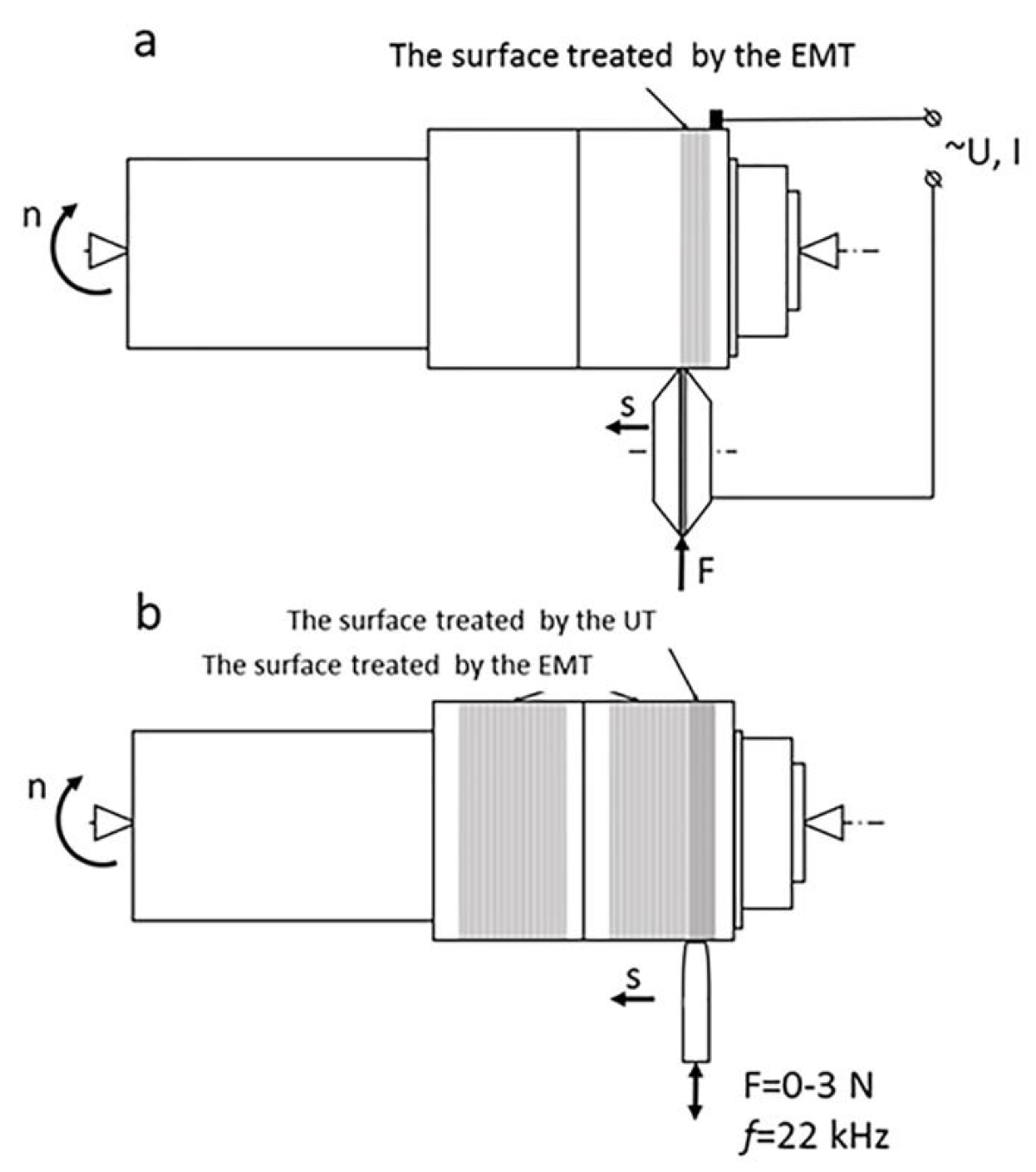
2.2. The Electromechanical Treatment

The EMT was chosen for surface hardening. The surface hardening of the cylindrical specimens was performed on a screw-cutting lathe. The EMT was performed using the protocol, which was described earlier [22]. In this work, a scheme with a single contact roller (Figure 2a) was used for the surface hardening. A contact welding transformer was used for the power supply. The control of the current in the secondary circuit was carried out by means of a thyristor power regulator. A contact electrode was used for resistive surface heating. The contact electrode had the shape of a roller and was made from WC-6Co. The roller was 38 mm in diameter and had the width of the contact surface of 0.5 mm. The contact area between the roller and the specimen surface was determined by the diameter of the roller and the specimen, as well as the width of the contact surface of the roller. A dynamometric device was used to press the roller on the surface of the specimen. The pressure of the roller on the specimen surface was set by the compression force of the spring. The contact area between the roller and the specimen surface was approximately 1 mm2. The compression force of the spring was 150 N. The linear velocity of the heating zone was determined by the rotation speed of the lathe spindle and the diameter of the specimen. The longitudinal displacement of the contact heating zone was set by the feed of the tool holder. Water cooling was used to protect the specimen surface and the roller from overheating. The water jet was supplied to the point of contact between the surface of the specimen and the roller. Therefore, the surface was simultaneously cooled to accelerate the hardening process, as well as the roller was cooled to increase its resource. The specimens #5–12 were treated by the EMT.
In our other articles we have already evaluated the effect of current density, linear speed, feed rate, and contact force with different parameters. Therefore, the optimal of them were determined earlier [27]. The main modes of the EMT are summarized in the Table 1.

2.3. The Ultrasonic Treatment

The ultrasonic treatment (UT) of the specimen surface was done after the EMT. The UT of the cylindrical specimens was performed on the same screw-cutting lathe (Figure 2b, SAMAT, Samara, Russia). The equipment contained an ultrasonic generator with a power output of 0.3 kW and a frequency of 21.6 kHz (BUFO, Saint Petersburg, Russia). The high frequency impacts were produced by a cylindrical WC–6Co pin of 5 mm in diameter.
The specimens #9–12 were treated by the UT. The linear velocity of the treated zone was determined by the rotation speed of the lathe spindle and the diameter of the specimen. The longitudinal displacement was set by the feed of the tool holder. Water cooling was used to protect the specimen surface and the cylindrical pin from overheating. The main modes of the UT are summarized in the Table 1.

2.4. Analysis of Surface

The specimens #1, 5, 9 were taken to determine the properties of the surface. The specimen #1 had no additional treatment. The specimen #5 was treated by the EMT. The specimen #9 was treated by the EMT and then treated by the UT.
To develop the samples with cross-section, the specimens #1, 5, 9 were cut, mounted in plastic and polished. 1 µm diamond suspension was used for the last polishing stage.
After polishing, the samples were washed with ethyl alcohol and dried. Then the cross-sections of the specimens were etched in the bath 4:1 H2O-HNO3 for metallography.
An optical microscope (Carl Zeiss Jenavert Interphako, Carl Zeiss, Oberkochen, Germany) was used to study the structure and the morphology of the surface. The investigation of the surface layer microstructure was carried out on a scanning electron microscope (Carl Zeiss NVision 40, Carl Zeiss, Oberkochen, Germany) with high resolution. Measurements of roughness, depth of the WEL, and length of the lath were made with the image analyzer, having software of VideoTest Structure 4.0 (VideoTest OOO, St. Petersburg, Russia).

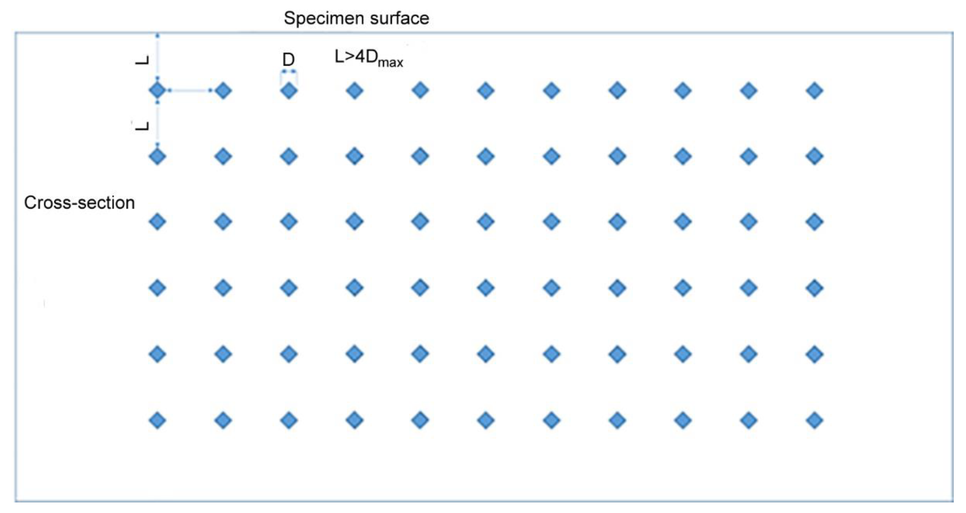
2.5. The Microhardness Test

The microhardness of the surface layer was analyzed. The Vickers indenter (PMT-3) was used to measure the microhardness of the surface layer. For each sample the microhardness was conducted 15 times and the obtained values were averaged. These measurements were taken by applying a load of 200 gf (1.96 N) and dwell time of 15 s (according to ISO 6507-1:2005).
The microhardness of the area of the thin surface layer was determined in the cross-section of the specimens under the load of 0.098 N (10 gf) for 15 s. The indentation of 10 gf was applied to the surface area (Figure 3) to measure the microhardness allocation in the surface after the treatment. The indentations were made by array in the cross-section of the surface layer. The distance between the indents was more than 4 diagonals of the indentation.

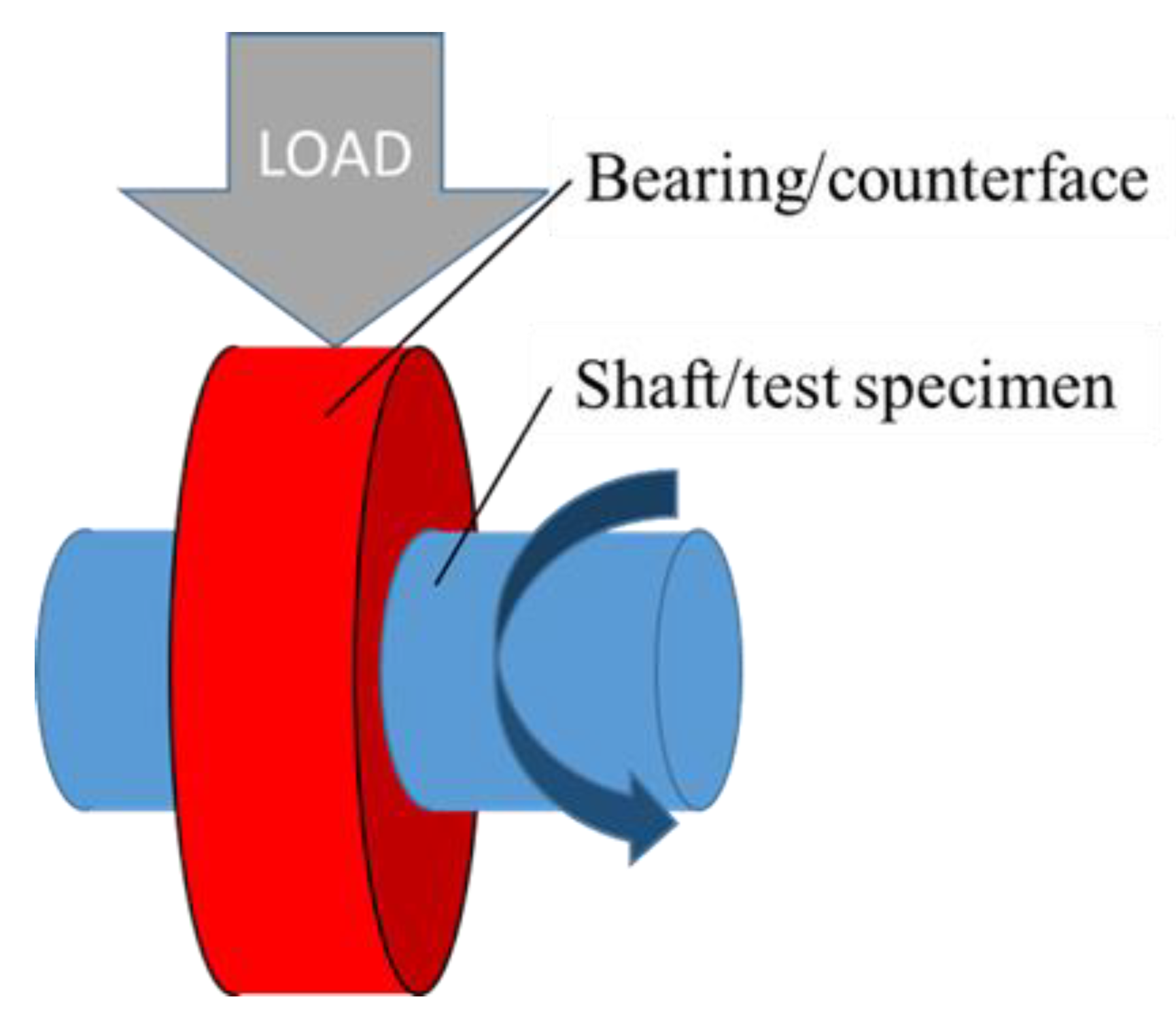
2.6. The Wear Resistance Test

The wear resistance test was carried out on the test machine SMT-1 (LLC “Tochpribor”, Ivanovo, Russia).
The test principle was the following: the bush was radially loaded against the shaft (Figure 4). In all the experiments, the linear velocity was kept constant at 1.68 m/s and the constant specific pressure was 0.24 MPa. The sliding distance was 18,000 m. Before and after the testing, both the test sample and the counterface were degreased and cleaned with acetone, then they were dried in warm air to ensure accuracy of measurements. The test samples were weighed on the analytical balance (AJH, Shinko Denshi, Tokyo, Japan) with accuracy of 0.1 mg before, during, and after each test to calculate the mass loss. The mass loss was converted to the volume loss using measured values of the samples densities. The wear rate was calculated.

2.7. The Corrosion Test

The corrosion tests were performed using a computerized potentiostat/galvanostat P-45X (Electrochemical Instruments, Chernogolovka, Russia).
The corrosion circuit consisted of three electrodes: a platinum sheet as a counter electrode, AISI 1045 as a working electrode, and a saturated calomel electrode (SCE) as a reference electrode. 0.9% NaCl solution was used as the electrolyte. The potentiostatic/galvanostatic study was performed from −0.5 to +0.5 V at a fixed scan rate of 1.0 mV/s.

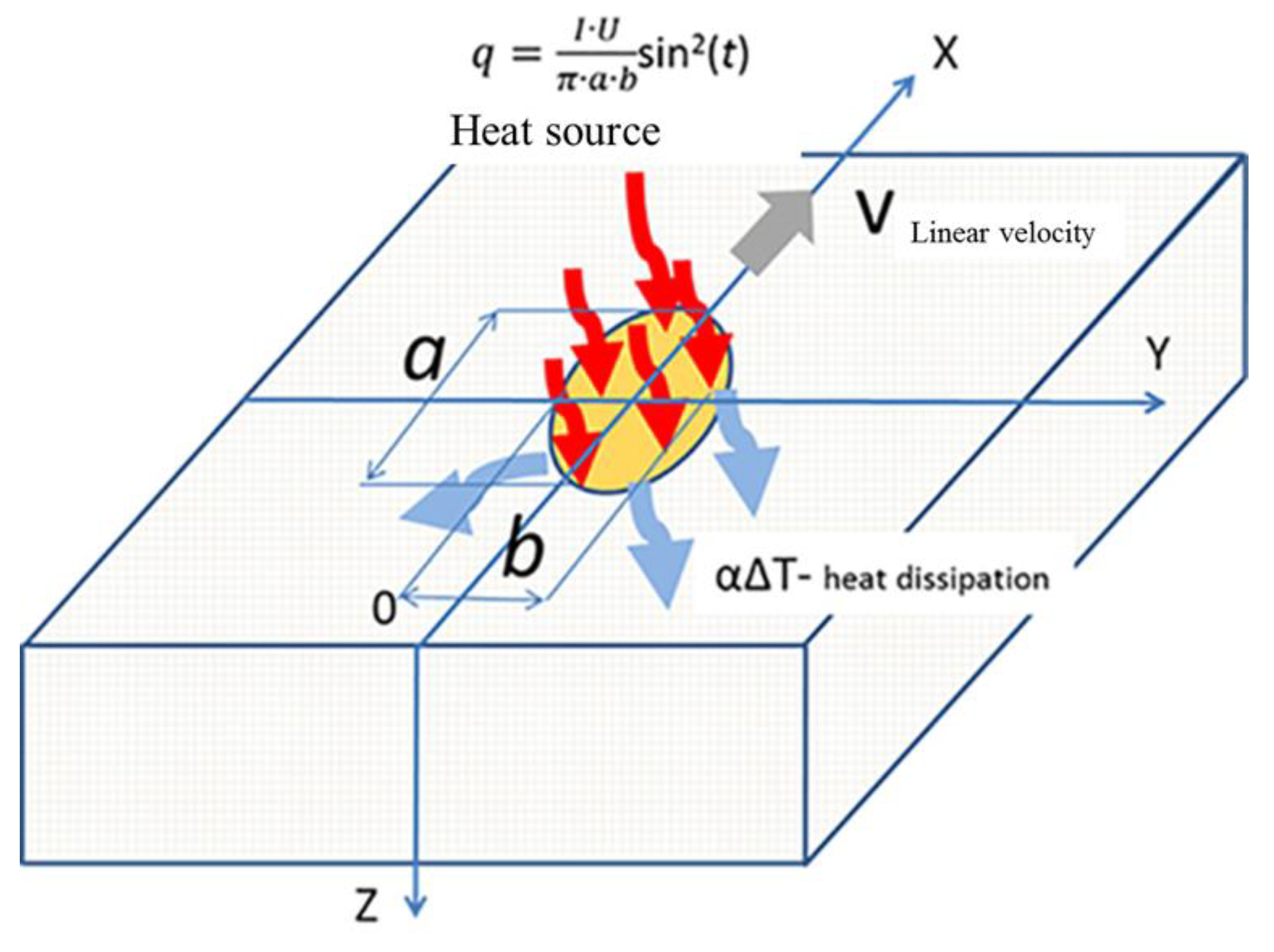
2.8. Numerical Modeling

The experimental investigation of the temperature in the contact zone between the roller and the treated surface cannot be performed by the optical pyrometer because the heating zone was closed by the treatment roller. For this reason, the temperature field in the surface layer, the rate of heating and cooling during the process of the EMT were numerically calculated. The mathematical approach to modeling of the temperature field was considered in detail in the paper [28]. The solution of the thermal conductivity equation (Fourier’s equation) was calculated using the finite difference method.
Figure 5 shows a half-space with a heat source, it simulates surface heating during resistive heating by the electrode. During the treatment the rise and fall of the electric current follow a sinusoidal function. The frequency of the electric current was 50 Hz. Consequently, after the start of the impulse the amplitude of the electric current had a maximum value every 5 ms. Then the amplitude of the electric current decreased to zero. An electric current of 400 A was used for the calculation, as in the experiment. The shape of the contact zone between the roller and the treated surface of the specimen was close to the elliptical. The dimensions of the heat source in the mathematical model were 1.7 and 0.6 mm, respectively. The contact area was approximately 1 mm2. The linear velocity of the heat source on the surface was assumed to be 2.5 m/min, which corresponded to the linear velocity of the resistive heating zone during experiment.

3. Results and Discussion

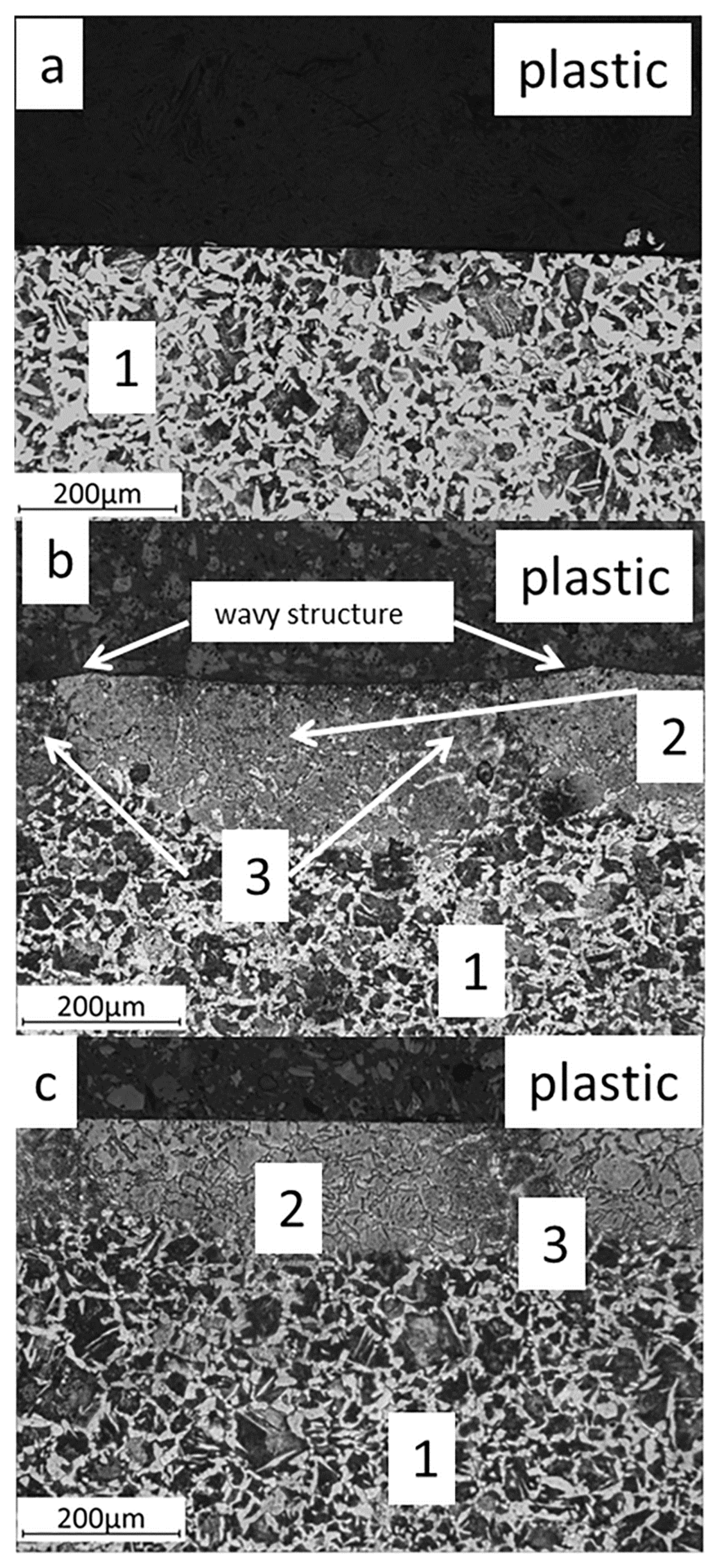
3.1. Macrostructure and Microstructure
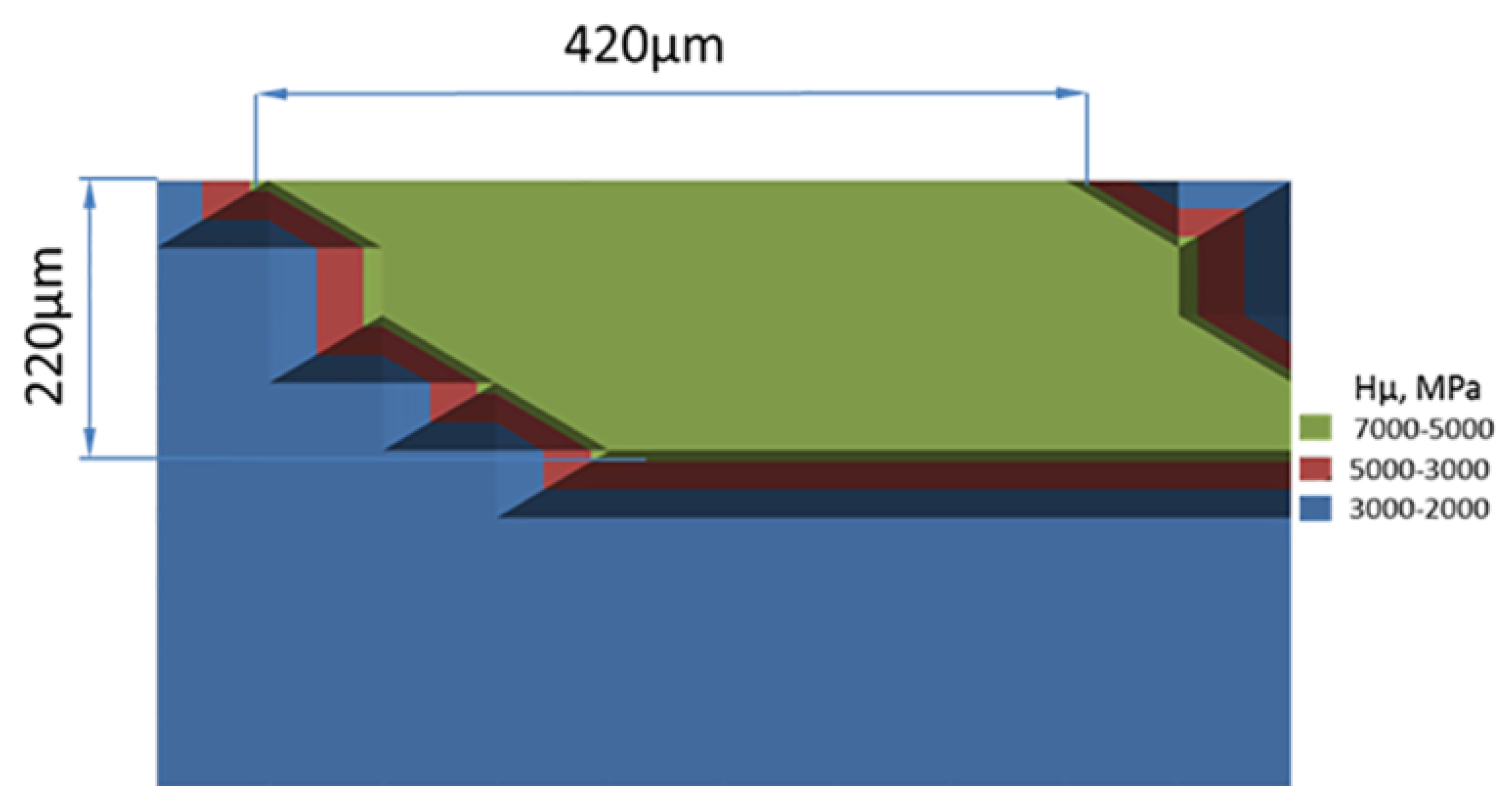
Figure 6 shows optical microscopy of the cross-sections of the base metal, the electromechanically treated steel, and the electromechanically and ultrasonically treated steel. Figure 6a shows ferrite-pearlite structure of the AISI 1045 steel. Figure 6b,c recovers the white etched layer (WEL) in the surface of the cross-section after the EMT. The average depth of the WEL is 240 ± 20 µm. The heat affected zones are observed between the WELs. The heat affected zones are formed while the roller moves longitudinally and some part of the previously fabricated WEL is heated the second time. The ferrite-pearlite structure is detected in the HAZ.
Figure 6b shows wavy structure. The period of the wavy structure is approximately 400 µm, due to the constant longitudinal movement of the roller (0.4 mm/rev). During the EMT with the single roller, the surface under the roller was resistively heated. The plasticity of the material increased. Under the influence of the contact pressure, the material of the surface layer was squeezed out from under the roller. The wavy structure of the surface was formed. A similar effect was found in the paper [25], where the wavy structure was formed during the EMT of the plasma sprayed coating. There is no wavy structure after finishing the surface by means of UT (Figure 6c). During the UT the wavy structure is deformed and the microrelief of the surface is improved. The average depth of the WEL after the additional UT was 210 ± 10 µm. During the UT the surface layer was heated, for this reason, the average depth of the WEL decreased.
In the previous study [27] the optical microscopy could not examine the structure of the WEL. In addition, the modelling of the electromechanical treatment [28] showed that the heating temperature of the surface layer was more than 1000 K. As a result, the γ-iron dissolved carbon and did so by consuming the cementite. Consequently, the austenite was formed in the surface layer. The cooling rate during the EMT process indicated that it exceeded 104 K/s, there was not enough time for the reverse transformation and the carbon could not diffuse out of its lattice. The austenite was distorted into tetragonal shape. The martensite was formed with the strained lattice. It was assumed that the martensite had grain size less than 0.5 µm and could not be examined by means of the optical microscopy.
In this study, we used high-resolution scanning electron microscopy for examination of the structure of the WEL. Figure 7 shows the microstructure of the WEL. The lath martensite is formed after the EMT of the surface of the AISI 1045. The length of the lath is 0.50 ± 0.25 µm and the average thickness is 100 ± 25 nm. The length and the thickness of the structure in the WEL are less than 0.5 µm each. For this reason, the optical microscopy could not be used for examination of the structure of the WEL. The comparison of the structure of the WEL after the EMT and after the laser treatment [26] showed that these types of the highly concentrated energy treatments gave the similar structure of the lath martensite in the surface layer of the AISI 1045 steel.

3.2. Microhardness

Table 2 shows the average microhardness of the surface layer and the average microhardness of the structural elements.
The microhardness of the WEL is 1.9 times more than the microhardness of the heat-affected zone. The average microhardness of the surface layer increases by 10% after the ultrasonic treatment. The microhardness at the load of 10 gf of the heat-affected zone of the surface layer increases, too.
Figure 8 shows the distributions of the microhardness at the load of 10 gf in the cross-section of the surface after the EMT. Three zones are observed in Figure 8. The first zone is the WEL, the microhardness of this area is more than 5000 MPa. The second zone is the heat affected zone, its microhardness changes from 3000 to 5000 MPa. The third zone has microhardness less than 3000 MPa, this is the base AISI 1045 steel.

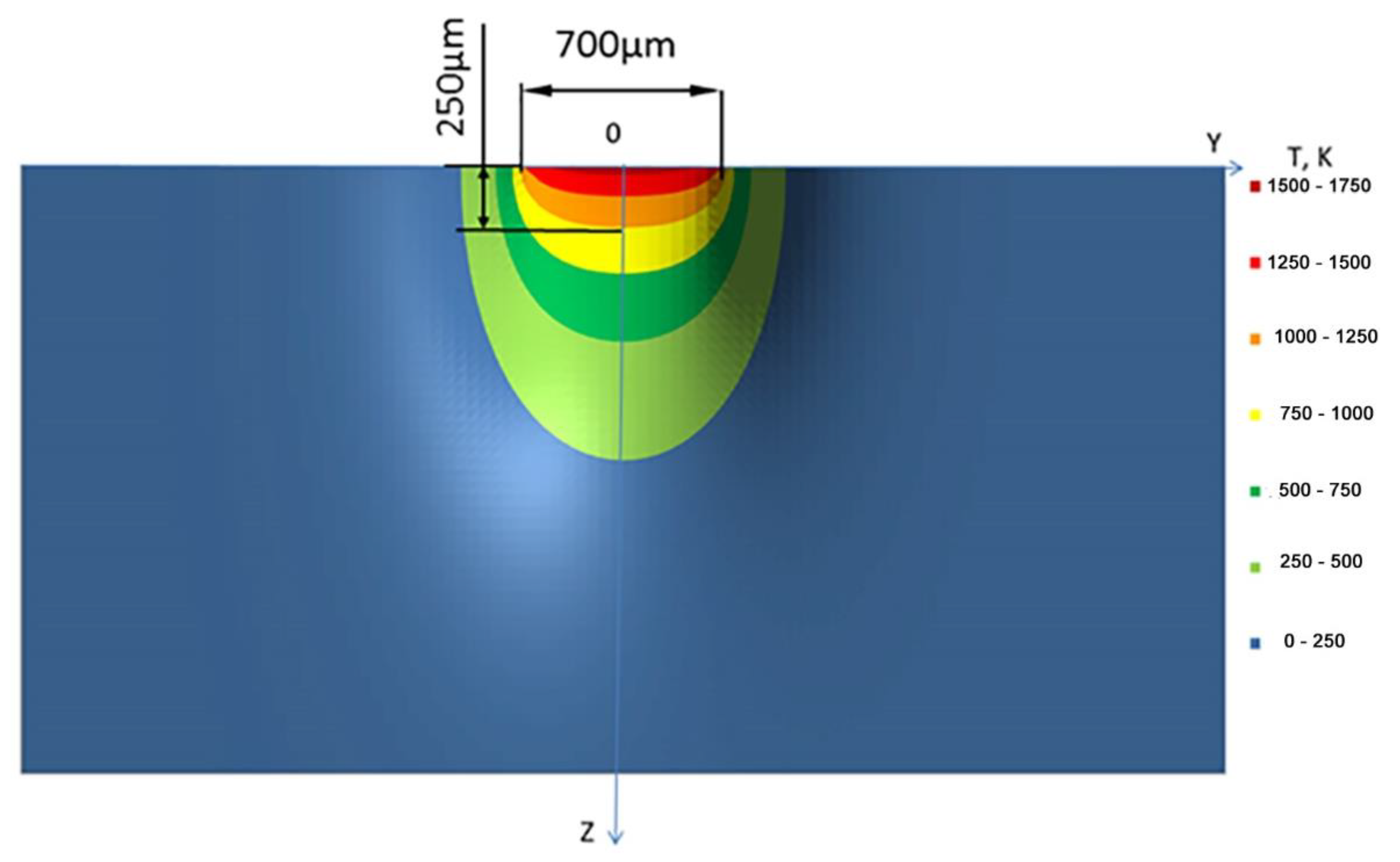
3.3. Numerical Modeling
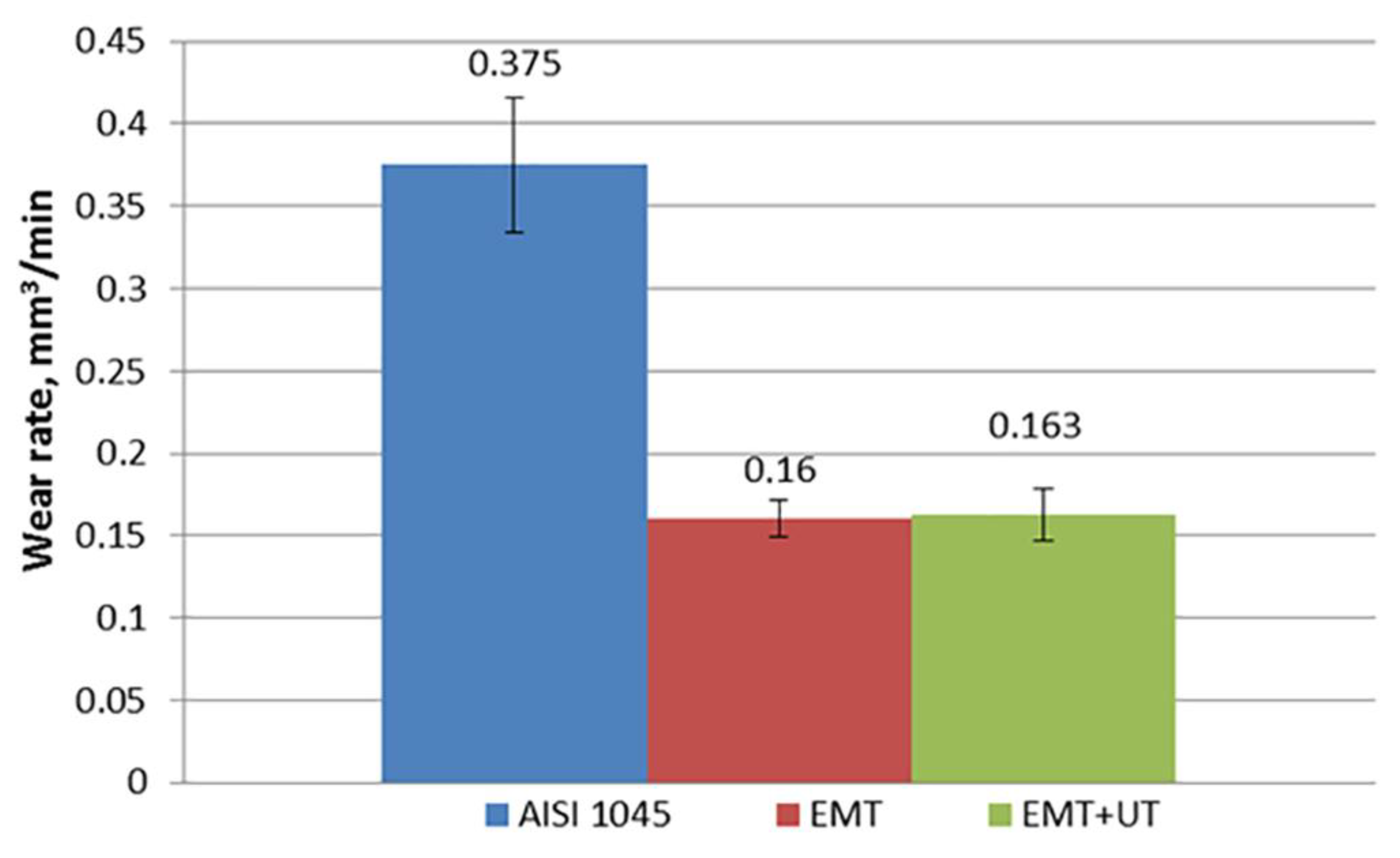
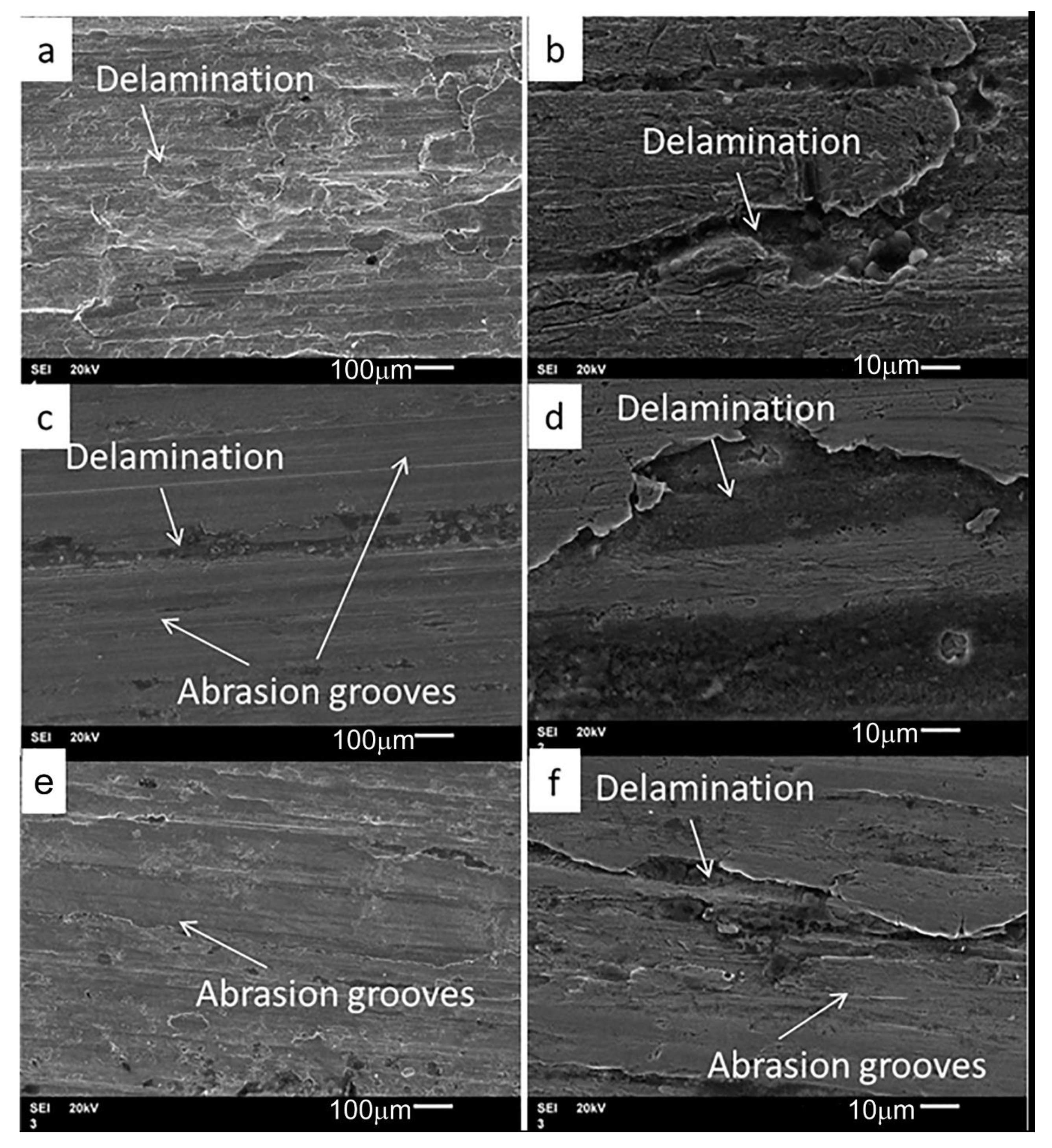
Figure 9 shows the temperature field in the cross-section of the half-space at a time of 25 ms after the start of the EMT. At this moment the maximum temperature was observed on the surface. The value of the heating temperature was 1700 K, which was higher than the melting temperature. But there was no melting of the surface layer because of the cooling of the base metal. The calculation of the cooling rate during the EMT process indicated that it exceeded 104 K/s. The calculated data were confirmed by structural studies (Figure 6b), which reiterated that there was no melting of the surface layer. The thickness of the heating zone (Figure 9) with a temperature higher than 1000 K and the thickness of the WEL (Figure 6b) were approximately equal. In addition, the analysis of the temperature distribution (Figure 9) and the distribution of the microhardness (Figure 8) showed that by moving to the region where the heating temperature was less than 1000 K the value of the microhardness reduced a lot.

3.4. Wear Behavior

The effect of the combination of the treatments on the wear behavior of the AISI 1045-improved steel was investigated by the sliding wear tests.
Figure 10 shows the wear rate of the specimens. The wear rate of the AISI 1045 steel decreased from 0.357 ± 0.050 mm3/min to 0.160 ± 0.011 mm3/min, because the microhardness at the load of 200 gf of AISI 1045 steel increased from 2000 ± 100 MPa to 5000 ± 400 MPa after the EMT. After the combination of the treatments the microhardness at the load of 200 gf increased to 5500 ± 400 MPa, but the wear rate remained stable.
Figure 11 shows the SEM image of the surface morphology of the produced wear scar by the sliding wear test. The sliding distance was 18,000 m, and the normal load was set as 113.4 N. In the case of the base metal, thick abrasion grooves, spalling, and delamination are observed at the wear scar, confirming that the dominant wear mechanism is a mix of adhesive and abrasive mechanisms. Spalling and delamination may cause unstable wear behavior, resulting in large fluctuation in the wear rate, as shown in Figure 10. Contrastingly, in the case of the EMT, relatively less spalling is detected; however, thick abrasion grooves are still observed at the wear scar. In the case of the combination of treatments the wear behavior was the same as after the EMT.

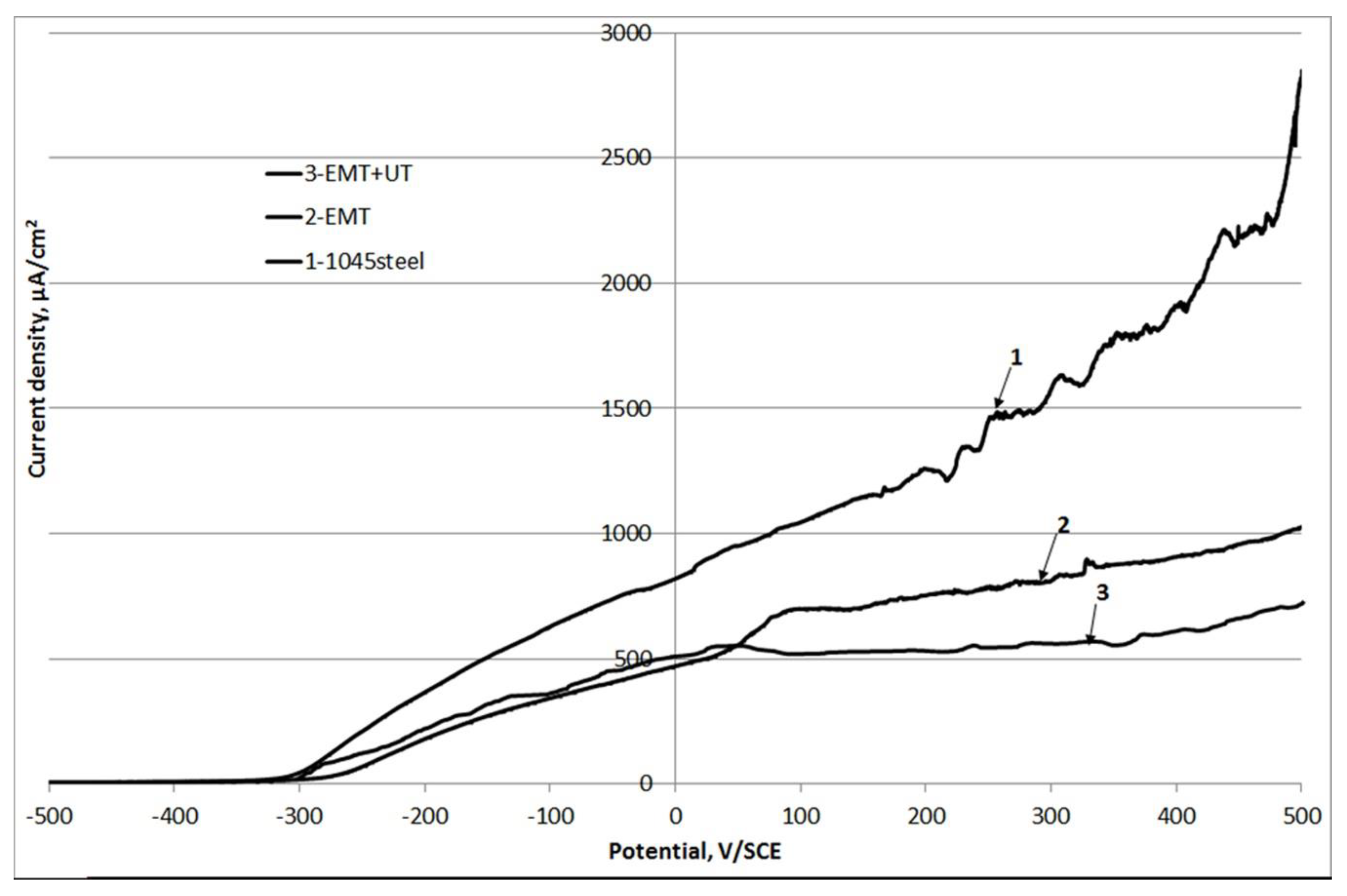
3.5. Corrosion Behavior

Figure 12 displays the polarization curves for the base metal (1), after the EMT (2), and after combination of the EMT + UT (3).
For the base metal, the corrosion potential is found to be −0.503 V/SCE. The marginal shift in the corrosion potential to the noble direction (−0.484 V/SCE) is observed on the surface of the sample after the EMT. In the case of the combination of the EMT + UT, the corrosion potential is shifted to −0.496 V/SCE.
After the EMT and the combination of the treatments the growth of the polarization curves is slower. The interval from 100 mV to 350 mV shows the effect of the passivation for polarization curves on the surface of the sample after the combination of the treatments.
When the corrosion potential is 500 V/SCE, the anodic current density tends to be diverse. The anodic current density of the AISI 1045 steel is 2828 µA/cm2. After the EMT the anodic current density decreases to 1025 µA/cm2. The minimal anodic current density is 728 µA/cm2 and this value is observed after the combination of the treatments.
This study estimated the influence of the combination of the treatments on the wear and corrosion behavior of AISI 1045-improved steel. However, the mechanical properties such as yield strength and fatigue strength also have an impact on the lifetime of the steel. The correlation between the microstructure and the mechanical properties after the combination of the treatments will be investigated in future researches.
The EMT allows to perform the hardening process on a lathe. Therefore, the hardening is carried out on the same equipment. There is no need to use additional rooms or equipment. In addition, the EMT allows strengthening of local areas, for example, cutter slots or fillets of shafts. It is also possible to strengthen large-sized items or items with complex geometry.
The microstructure of the white layer, formed during the hardening of the EMT and the laser hardening, is the same. Therefore, the EMT can replace the laser hardening, because the cost of the equipment is several times lower.

4. Conclusions

During the EMT process the WEL was formed in the surface layer. The microhardness of the surface layer of steel AISI 1045 increased from 2000 ± 100 MPa to 5000 ± 400 MPa after the EMT. The high microhardness of the WEL was caused by the transformation of the structure of AISI 1045 steel from ferrite-perlite to lath martensitic with the average thickness less than 100 nm.
The formation of a fast-quenched structure of the WEL in the surface layer confirmed the calculated data of the cooling rate during the EMT process of more than 104 K/s.
The formation of the wavy structure during the EMT process was determined by the extrusion of the surface material from under the roller during the combined action of resistive heating and contact pressure. Therefore, the period of the wavy structure coincided with the step of the roller movement when scanning the surface of the cylindrical specimen.
The UT cleaned the wavy structure and increased the microhardness of the surface after the EMT up to 5500 ± 500 MPa. The wear resistance of treated using the EMT and the UT steel increased more than two times compared to the base steel.
The anodic current density of the surface of the AISI 1045 steel decreased two times after the EMT because of the formation of the white-etched layer. The anodic current density of the surface of the AISI 1045 steel was decreased three times after the combination of the treatments because of the hardening of the heat-affected zones which were formed during the EMT process.

Author Contributions

S.N.G.: supervision, validation, funding acquisition. A.Y.I.: surface treatment, investigation of the structure, conceptualization, writing—review and editing. M.V.P.: investigation of the tribology properties. I.N.Z.: software. O.G.K. and A.M.L.: preparation of the specimens, investigation of the corrosion properties. All authors have read and agreed to the published version of the manuscript.

Funding

This work was supported by the Russian Science Foundation (project No. 18-19-00599).

Acknowledgments

The authors are grateful to Yulia Ivannikova for the technical support.

Conflicts of Interest

The authors declare that they have no known competing financial interests or personal relationships that could have appeared to influence the work reported in this paper.

References

  1. Shiou, F.-J.; Cheng, C. Ultra-precision surface finish of NAK80 mould tool steel using sequential ball burnishing and ball polishing processes. J. Mater. Process. Technol. 2008, 201, 554–559. [Google Scholar] [CrossRef]
  2. Bell, T. Surface engineering of austenitic stainless steel. Surf. Eng. 2002, 18, 415–422. [Google Scholar] [CrossRef]
  3. Savaria, V.; Monajati, H.; Bridier, F.; Bocher, P. Measurement and correction of residual stress gradients in aeronautical gears after various induction surface hardening treatments. J. Mater. Process. Technol. 2015, 220, 113–123. [Google Scholar] [CrossRef]
  4. Rudnev, V.; Loveless, D.; Cook, R.; Black, M. Handbook of Induction Heating; Marcel Dekker: New York, NY, USA, 2003. [Google Scholar]
  5. Santhanakrishnan, S.; Dahotre, N.B. Laser surface hardening. In ASM Handbook on Heat Treating Irons and Steels; American Society for Materials (ASM) International: Materials, Park, OH, USA, 2013. [Google Scholar]
  6. Grum, J. Comparison of different techniques of laser surface hardening. J. Achiev. Mater. Manuf. Eng. 2007, 24, 17–25. [Google Scholar]
  7. Montross, C.S.; Wei, T.; Ye, L.; Clark, G.; Mai, Y.-W. Laser shock processing and its effects on microstructure and properties of metal alloys: A review. Int. J. Fatigue 2002, 24, 1021–1036. [Google Scholar] [CrossRef]
  8. Zou, J.; Zhang, K.; Hao, S.; Dong, C.; Grosdidier, T. Mechanisms of hardening, wear and corrosion improvement of 316L stainless steel by low energy high current pulsed electron beam surface treatment. Thin Solid Films 2010, 519, 1404–1415. [Google Scholar] [CrossRef]
  9. College, D.A.; Zhu, Y. Alleviating surface tensile stress in e-beam treated tool steels by cryogenic treatment. Mater. Sci. Eng. A 2018, 722, 167–172. [Google Scholar] [CrossRef]
  10. Zhang, K.; Ma, J.; Zou, J.; Liu, Y. Surface microstructure and property modifications in a duplex stainless steel induced by high current pulsed electron beam treatments. J. Alloy Compd. 2017, 707, 178–183. [Google Scholar] [CrossRef]
  11. Ismail, M.I.S.; Taha, Z. Surface Hardening of Tool Steel by Plasma Arc with Multiple Passes. Int. J. Technol. 2014, 5, 79–87. [Google Scholar] [CrossRef] [Green Version]
  12. Wang, L.M.; Liu, J.B.; Huang, B.X. Microstructure and Performance of Multiple Tracks Lap-Joint Coating by Plasma Cladding. Appl. Mech. Mater. 2011, 109, 42–45. [Google Scholar] [CrossRef]
  13. Som, A.I. Iron-based alloy for plasma-powder surfacing of screw conveyors of extruders and injection molding machines. Pat. Weld. J. 2016, 7, 21–25. [Google Scholar] [CrossRef] [Green Version]
  14. Lesyk, D.; Martinez, S.; Mordyuk, B.; Dzhemelinskyi, V.; Lamikiz, A.; Prokopenko, G.; Milman, Y.; Grinkevych, K. Microstructure related enhancement in wear resistance of tool steel AISI D2 by applying laser heat treatment followed by ultrasonic impact treatment. Surf. Coat. Technol. 2017, 328, 344–354. [Google Scholar] [CrossRef]
  15. Lv, Y.; Lei, L.; Sun, L. Influence of different combined severe shot peening and laser surface melting treatments on the fatigue performance of 20CrMnTi steel gear. Mater. Sci. Eng. A 2016, 658, 77–85. [Google Scholar] [CrossRef]
  16. Qi, X.B.; Zhu, S. Effect of electric contact surface treatment on microstructure and wear behaviour of ductile iron. Mater. Sci. Technol. 2013, 29, 1310–1316. [Google Scholar] [CrossRef]
  17. Wang, Y.; Zhu, S.; Gu, W.; Qi, X. Electric Contact Strengthening to Improve the Bonding between Thermally Sprayed 316 Stainless Steel Coating and 45# Steel Substrate. Exp. Tech. 2010, 35, 66–70. [Google Scholar]
  18. YWang, Y.; Zhu, S.; Gu, W.; Qi, X. Electric Contact Strengthening to Improve the Bonding Between WC-Co Coating and 45# Steel Substrate. J. Therm. Spray Technol. 2010, 19, 1142–1146. [Google Scholar]
  19. Xu, M.; Zhu, S.; Ding, H. Electrical contact strengthening of induction-clad Ni–40% WC composite coatings on 40Cr substrates. Surf. Coat. Technol. 2015, 279, 32–38. [Google Scholar] [CrossRef]
  20. Bagmutov, V.P.; Kalita, V.I.; Zakharova, E.B.; Komlev, D.I.; Ivannikov, A.Y.; Zakharov, I.N.; Kosogorov, A.V. Ultradisperse and nano structures in plasma coatings hardened by electromechanical treatment. Steel Transl. 2013, 43, 351–355. [Google Scholar] [CrossRef]
  21. Ivannikov, A.Y.; Kalita, V.; Komlev, D.; Radyuk, A.; Bagmutov, V.; Zakharov, I.N.; Parshev, S. The effect of electromechanical treatment on structure and properties of plasma sprayed Ni–20Cr coating. J. Alloy Compd. 2016, 655, 11–20. [Google Scholar] [CrossRef]
  22. Ivannikov, A.Y.; Kalita, V.I.; Komlev, D.I.; Radyuk, A.; Bagmutov, V.; Zakharov, I.N.; Parshev, S. The effect of electromechanical treatment on structure and properties of plasma sprayed Fe-6W-5Mo-4Cr-2V-C coating. Surf. Coat. Technol. 2018, 335, 327–333. [Google Scholar] [CrossRef]
  23. Cordovilla, F.; García-Beltrán, Á.; Sancho, P.; Domínguez, J.; Ruiz-De-Lara, L.; Ocaña, J.L. Numerical/experimental analysis of the laser surface hardening with overlapped tracks to design the configuration of the process for Cr-Mo steels. Mater. Des. 2016, 102, 225–237. [Google Scholar] [CrossRef]
  24. Ben Qi, X.; Zhu, S.G. Study on Electric Contact Heating for Nodular Cast Iron 600-3. Appl. Mech. Mater. 2012, 154, 316–321. [Google Scholar]
  25. Ivannikov, A.Y.; Kalita, V.I.; Komlev, D.I.; Radyuk, A.A.; Alpatov, A.V.; Zakharov, I.N.; Grigoriev, S.N.; Prozhega, M.V. The Effect of Electromechanical Treatment on Structure and Properties of Plasma-Sprayed Fe-30Cr Coating. J. Therm. Spray Technol. 2019, 28, 883–892. [Google Scholar] [CrossRef]
  26. Lesyk, D.; Mordyuk, B.; Martinez, S.; Iefimov, M.; Dzhemelinskyi, V.; Lamikiz, A. Influence of combined laser heat treatment and ultrasonic impact treatment on microstructure and corrosion behavior of AISI 1045 steel. Surf. Coat. Technol. 2020, 401, 126275. [Google Scholar] [CrossRef]
  27. Dudkina, N.G.; Zakharov, I.N.; Ermolov, V.S.; Ivannikov, A.Y. Dependence of microhardness of a regular discrete structures of the surface layer of a mild steel on the conditions of electromechanical treatment. Probl. Mashinostr. Nadezhn. Mashin 2006, 5, 62–68. (In Russian) [Google Scholar]
  28. Bagmutov, V.P.; Denisevich, D.S.; Zakharov, I.N.; Ivannikov, A.Y. Nonlinear and coupled thermal effects during finite element simulation of contact thermoforce surface hardening. PNRPU Mech. Bull. 2017, 1, 233–250. [Google Scholar]
Figure 1. The scheme of the specimens for the wear test: (a) shaft, (b) bearing.
Metals 10 01669 g001
Figure 2. The principal schematic diagram of the surface treatment: (a) the electromechanical treatment, (b) the ultrasonic treatment.
Metals 10 01669 g002
Figure 3. The schematic diagram of indentation at the load of 10 gf in the cross-section of the specimen.
Metals 10 01669 g003
Figure 4. Test principle: bearing is radially loaded against shaft.
Metals 10 01669 g004
Figure 5. The model of a half-space with a moving thermal source on the surface.
Metals 10 01669 g005
Figure 6. Optical microscopy of the cross-section: (a) AISI 1045, (b) after the electromechanical treatment (EMT), (c) after the combination of the treatments (EMT + UT). 1—the ferrite-pearlite structure, 2—the WEL, 3—the HAZ.
Metals 10 01669 g006
Figure 7. SEM of the white etched layer.
Metals 10 01669 g007
Figure 8. Distributions of the microhardness at the load of 10 gf in the cross-section of the surface after the EMT.
Metals 10 01669 g008
Figure 9. The calculated distribution of the temperature in the cross-section of the surface layer at 25 ms during the EMT.
Metals 10 01669 g009
Figure 10. The wear rate of the specimens.
Metals 10 01669 g010
Figure 11. The worn surface morphologies from the sliding wear tests after 18,000 m of sliding distance at a normal load of 113.4 N (a,b—AISI 1045, c,d—after the EMT, e,f—after the EMT + UT).
Metals 10 01669 g011
Figure 12. The polarization curves of the base AISI 1045 (1), the EMT treated surface AISI 1045 (2), and the EMT + UT treated surface AISI 1045 (3) in 0.9% NaCl solution.
Metals 10 01669 g012
Table 1. Modes of the treatments.
TreatmentFeed Rate s, mm/revLinear Velocity V, m/minDensity of the Electric Current j, A/mm2Contact Force P, N
EMT0.42.5400250
UT0.16-3
Table 2. Microhardness of the cross-section of the surface layer.
Type of TreatmentMicrohardness, MPa
200 gf10 gf
WELHeat Affected Zone
As-received AISI 10452000 ± 1002000 ± 150-
EMT5000 ± 4006800 ± 5003500 ± 500
EMT + UT5500 ± 4007000 ± 5004500 ± 500
Publisher’s Note: MDPI stays neutral with regard to jurisdictional claims in published maps and institutional affiliations.

