1. Introduction
Aluminum/steel composite plate is well known as a kind of common lightweight composite material and has been widely used in automobile, ship, aerospace and pressure vessel fields [
1,
2,
3]. Compared with the single metallic materials, the aluminum/steel composite plate not only has superior properties but also greatly reduces the weight of equipment. However, the different physical and chemical properties of aluminum and steel make them unable to form effective and strong joint by fusion welding.
Explosive welding is one of the joining methods belonging to the solid state welding process. The metal plates are joined together under a very high pressure and there is local plastic deformation at the interface. The interfaces after explosive welding are almost metallurgical bondings and even stronger than the base metals. Similar and dissimilar materials can be joined by the explosive welding [
4]. However, steel cuttings, holes, cracks and other defects caused by the high temperature and the excessive explosion pressure restrict the application of composite plates [
5,
6,
7].
Friction stir processing (FSP) developed from friction stir welding (FSW) has been invested in improving the performance of materials [
8,
9,
10]. Gupta et al. found that FSP can refine grain structures and eliminate defects like porosity in the matrix of AZ31 magnesium alloy [
11]. Barmouz found that FSP can refine the second particle’s size and enhance the dispersion distribution of the second particles for Cu/SiC composites [
12]. Nakata found that FSP can improve the hardness and tensile strength for ADC12 aluminum die casting alloy by grain refinement and disappearance of cold flake [
13]. Pourali et al. investigated the different tool rotations and weld speeds for lap weld joint of 1100Al/St37 steel composite plate. They found that the tensile strength of composite with high tool rotation and low weld speed is superior since the interface of this joint formed a properly thick bonding layer compared with other parameters [
14].
However, FSP can also reduce the mechanical properties when the parameters are inappropriate. Gupta et al. also found that tunnel defects are both formed in AZ31 magnesium alloy whether in the truncated conical tool or the cylindrical tool [
11]. Kima et al. found that tunnel defects are easily formed in ADC12 aluminum die casting alloy during welding [
15].
In order to improve the mechanical properties of composite plate, obtaining the appropriate interface is the main method since the interface of composite plate is the main carrying structure during service. Thus, there are two main factors that affecting the microstructures and mechanical properties of composite plate after FSP with different passes, which include the interface connections and the tunnel defects.
In the first part, the bonding strength of composite plate is related to the interface connection mechanisms, which include the mechanical connection and the metallurgical bonding. Pourali et al. found that mechanical connections are the main connection methods of aluminum/steel composite plate under the condition of low welding speed [
14]. During explosive welding, the energies of explosion flow cause some of the steel and aluminum soften or even melt, mix and finally form the morphologies of hooks or vortexes at the interface [
16,
17]. Meanwhile, defects such as steel cuttings and microcracks caused by explosion weaken the strength of composite. Since FSP can refines the second particles size and reduces the cold flake of aluminum die casting alloy [
12,
13], the steel cuttings and microcracks could also be repaired by strong stirring of aluminum. Therefore, FSP is proposed to repair the defects formed by explosive welding.
The metallurgical bondings mainly include intermetallic compounds (IMCs) and barely have few solid solutions. In the process of welding, the formation mechanisms of interface layer are diffusion and metallurgical reaction in the result of temperature and pressure [
18,
19]. Since the mutual solubility of aluminum and steel is few, the mechanical properties are poor even if forming the solid solution. Therefore, IMCs are interface connections basis for the composite plate. Fe
3Al, FeAl, Fe
2Al
5, FeAl
2 and FeAl
3 (Fe
4Al
13) are the dominating forming IMCs during welding process. According to the content ratio of aluminum to steel, IMCs can be divided into two categories—IMCs rich in Fe which are rigid and IMCs rich in Al which are toughness [
20,
21,
22,
23,
24]. In addition, Bozzi et al. found that when the thickness of IMCs is 8 μm, mechanical properties of the composite plate are the best. While the thickness increases to 42 μm, mechanical properties of the composite plate are the worst [
25]. In other words, the thickness of IMCs for the composite plate is a key factor influencing its mechanical properties. When the thickness of IMCs is lower than a certain value, the mechanical properties of composite plate improve with the IMCs thickness increasing [
26,
27]. With the FSP passes increasing, the accumulated heat input increases and finally IMCs thickness is also getting thicker. However, too thick IMCs decrease the bonding strength of interface. Thus, it is necessary to use M-FSP for obtaining the appropriate thickness of IMCs.
In the second part, tunnel defects are usually found in the composite plate after the single-pass FSP [
11,
15,
16,
28]. Kima investigated different tool plunge downforces of FSW for ADC12 aluminum die casting alloy. They found that tunnel defects are caused by the insufficient heat input [
15]. Javad et al. presented a mathematical model for the heat input generation during friction stir welding of 1060 aluminum alloy. They also found that the insufficient heat input can form tunnel defects in the matrix of aluminum during welding [
29]. Due to the insufficient heat input, the insufficient flow of material stirred causes the tunnel defects. Therefore, the heat input is increased by increasing the number of stirring passes to eliminate the tunnel defects. Meanwhile, the plastic flow of aluminum can also increase with the increase of passes. Thus, M-FSP is used to repair the tunnel defects in the composite plate.
In order to find the relationships between microstructures and mechanical properties of aluminum/steel composite plate after FSP with different passes, the 1060Al/Q235 composite plates are chosen as the objects to study on account of its superior plasticity and extensive application. Meanwhile, compared to other alloys, the 1060Al and the Q235 have fewer alloying components than other materials, which makes it easy to study the interface fracture models. The optimized pass of FSP is obtained by microstructures observation and mechanical properties investigation. The above research provided a good data basis in the production of aluminum/steel composite plate in the future.
Author Contributions
Conceptualization, J.W. and B.L.; methodology, C.C.; validation, J.W. and B.L.; investigation, J.W. and Y.C.; data curation, Y.C.; writing—original draft preparation, J.W.; writing—review and editing, C.C.; supervision, J.W.; project administration. All authors have read and agreed to the published version of the manuscript.
Funding
This work was funded by the National Natural Science Foundation of China (No. 51505293), the Natural Science Foundation of Jiangsu Province (No. BK20190684), the Natural Science Research of the Jiangsu Higher Education Institutions of China (No. 18KJB460016) and the Introduce Talent Special Funding for Scientific Research at Nanjing Tech University (No. 39802124).
Conflicts of Interest
The authors declare no conflict of interest.
References
- Kaya, Y.; Kahraman, N. An investigation into the explosive welding/cladding of Grade A ship steel/AISI 316L austenitic stainless steel. Mater. Des. 2013, 52, 367–372. [Google Scholar] [CrossRef]
- Feistauer, E.E.; Bergmann, L.A.; Barreto, L.S.; dos Santos, J.F. Mechanical behaviour of dissimilar friction stir welded tailor welded blanks in Al–Mg alloys for Marine applications. Mater. Des. 2014, 59, 323–332. [Google Scholar] [CrossRef] [Green Version]
- Acarer, M.; Demir, B. An investigation of mechanical and metallurgical properties of explosive welded aluminium–dual phase steel. Mater. Lett. 2008, 62, 4158–4160. [Google Scholar] [CrossRef]
- Findik, F. Recent developments in explosive welding. Mater. Des. 2011, 32, 1081–1093. [Google Scholar] [CrossRef]
- Acarer, M.; Gülenç, B.; Findik, F. Investigation of explosive welding parameters and their effects on microhardness and shear strength. Mater. Des. 2003, 24, 659–664. [Google Scholar] [CrossRef]
- Li, X.; Ma, H.; Shen, Z. Research on explosive welding of aluminium alloy to steel with dovetail grooves. Mater. Des. 2015, 87, 815–824. [Google Scholar] [CrossRef]
- Szecket, A. A wavy versus straight interface in the explosive welding of aluminium to steel. J. Vac. Sci. Technol. A Vac. Surf. Film. 1985, 3, 2588–2593. [Google Scholar] [CrossRef]
- Thomas, W.M.; Nicholas, E.D.; Needham, J.C.; Murch, M.G.; Temple-Smith, P.; Dawes, C.J. Friction Stir Butt Welding. International Patent International Patent Application Number PCT/GB92/02203 and GB Patent Application 9125978.8. 6 December 1991. [Google Scholar]
- Ma, Z.Y.; Mishra, R.S.; Mahoney, M.W.; Grimes, R. High strain rate superplasticity in friction stir processed Al–Mg–Zr alloy. Mater. Sci. Eng. A 2003, 351, 148–153. [Google Scholar] [CrossRef]
- Hao, H.L.; Ni, D.R.; Huang, H.; Wang, D.; Xiao, B.L.; Nie, Z.; Ma, Z.Y. Effect of welding parameters on microstructure and mechanical properties of friction stir welded Al–Mg–Er alloy. Mater. Sci. Eng. A 2013, 559, 889–896. [Google Scholar] [CrossRef]
- Gupta, A.; Singh, P.; Gulati, P.; Shukla, D.K. Effect of Tool rotation speed and feed rate on the formation of tunnel defect in Friction Stir Processing of AZ31 Magnesium alloy. Mater. Today Proc. 2015, 2, 3463–3470. [Google Scholar] [CrossRef]
- Barmouz, M.; Givi, M.K.B. Fabrication of in situ Cu/SiC composites using multi-pass friction stir processing: Evaluation of microstructural, porosity, mechanical and electrical behavior. Compos. Part A Appl. Sci. Manuf. 2011, 42, 1445–1453. [Google Scholar] [CrossRef]
- Nakata, K.; Kim, Y.G.; Fujii, H.; Tsumura, T.; Komazaki, T. Improvement of mechanical properties of aluminum die casting alloy by multi-pass friction stir processing. Mater. Sci. Eng. A 2006, 437, 274–280. [Google Scholar] [CrossRef]
- Pourali, M.; Abdollah-Zadeh, A.; Saeid, T.; Kargar, F. Influence of welding parameters on intermetallic compounds formation in dissimilar steel/aluminium friction stir welds. J. Alloy Compd. 2017, 715, 1–8. [Google Scholar] [CrossRef]
- Kim, Y.G.; Fujii, H.; Tsumura, T.; Komazaki, T.; Nakata, K. Three defect types in friction stir welding of aluminum die casting alloy. Mater. Sci. Eng. A 2006, 415, 250–254. [Google Scholar] [CrossRef]
- Fereiduni, E.; Movahedi, M.; Kokabi, A.H. Dissimilar Al/steel friction stir spot welding: To penetrate into the lower steel sheet or not? Sci. Technol. Weld. Join. 2016, 21, 466–472. [Google Scholar] [CrossRef]
- Coelho, R.; Kostka, A.; Santos, J.F.D.; Kaysser-Pyzallaa, A. Friction-stir dissimilar welding of aluminium alloy to high strength steels: Mechanical properties and their relation to microstructure. Mater. Sci. Eng. A 2012, 556, 175–183. [Google Scholar] [CrossRef]
- Ogura, T.; Saito, Y.; Nishida, T.; Nishida, H.; Yoshida, T.; Omichi, N.; Fujimoto, M.; Hirose, A. Partitioning evaluation of mechanical properties and the interfacial microstructure in a friction stir welded aluminium alloy/stainless steel lap joint. Scr. Mater. 2012, 66, 531–534. [Google Scholar] [CrossRef]
- Sun, Y.F.; Fujii, H.; Takaki, N.; Okitsu, Y. Microstructure and mechanical properties of dissimilar Al alloy/steel joints prepared by a flat spot friction stir welding technique. Mater. Des. 2013, 47, 350–357. [Google Scholar] [CrossRef]
- Haghshenas, M.; Abdel-Gwad, A.; Omran, A.M.; Gökçe, B.; Sahraeinejad, S.; Gerlich, A.P. Friction stir weld assisted diffusion bonding of 5754 aluminium alloy to coated high strength steels. Mater. Des. 2014, 55, 442–449. [Google Scholar] [CrossRef]
- Ramachandran, K.K.; Murugan, N.; Shashi Kumar, S. Effect of tool axis offset and geometry of tool pin profile on the characteristics of friction stir welded dissimilar joints of aluminium alloy AA5052 and HSLA steel. Mater. Sci. Eng. A 2015, 639, 219–233. [Google Scholar] [CrossRef]
- Chen, Z.W.; Yazdanian, S.; Littlefair, G. Effects of tool positioning on joint interface microstructure and fracture strength of friction stir lap Al-to-steel welds. J. Mater. Sci. 2013, 48, 2624–2634. [Google Scholar] [CrossRef]
- Movahedi, M.; Kokabi, A.H.; Reihani, S.M.S.; Najafi, H.; Farzadfar, S.A.; Cheng, W.J.; Wang, C.J. Growth kinetics of Al–Fe intermetallic compounds during annealing treatment of friction stir lap welds. Mater. Charact. 2014, 90, 121–126. [Google Scholar] [CrossRef]
- Coelho, R.S.; Kostka, A.; Sheikhi, S.; dos Santos, J.; Pyzalla, A.R. Microstructure and Mechanical Properties of an AA6181-T4 Aluminium Alloy to HC340LA High Strength Steel Friction Stir Overlap Weld. Adv. Eng. Mater. 2008, 10, 961–972. [Google Scholar] [CrossRef]
- Bozzi, S.; Helbert-Etter, A.L.; Baudin, T.; Criqui, B.; Kerbiguet, J.G. Intermetallic compounds in Al 6016/IF-steel friction stir spot welds. Mater. Sci. Eng. A 2010, 527, 4505–4509. [Google Scholar] [CrossRef]
- Movahedi, M.; Kokabi, A.H.; Reihani, S.M.S.; Najafi, H. Effect of tool travel and rotation speeds on weld zone defects and joint strength of aluminium steel lap joints made by friction stir welding. Sci. Technol. Weld. Join. 2012, 17, 162–167. [Google Scholar] [CrossRef]
- Tanaka, T.; Morishige, T.; Hirata, T. Comprehensive analysis of joint strength for dissimilar friction stir welds of mild steel to aluminium alloys. Scr. Mater. 2009, 61, 756–759. [Google Scholar] [CrossRef]
- Wang, J.; Lu, X.F.; Chen, C.; Li, B.; Ma, Z.Y. Improve the quality of 1060Al/Q235 explosive composite plate by friction stir processing. J. Mater. Res. Technol. 2020, 9, 42–51. [Google Scholar] [CrossRef]
- Rasti, J. Study of the welding parameters effect on the tunnel void area during friction stir welding of 1060 aluminum alloy. Int. J. Adv. Manuf. Technol. 2018, 97, 2221–2230. [Google Scholar] [CrossRef]
- Pal, S.; Phaniraj, M.P. Determination of heat partition between tool and workpiece during FSW of SS304 using 3D CFD modeling. J. Mater. Process. Technol. 2015, 222, 280–286. [Google Scholar] [CrossRef]
- Prangnell, P.B.; Heason, C.P.; Colligan, K.J. Grain structures in Al-alloy friction stir welds observed by stop-action technique. Int. J. Offshore Polar Eng. 2004, 14, 289–295. [Google Scholar]
- Hasan, A.F.; Bennett, C.J.; Shipway, P.H. A numerical comparison of the flow behaviour in Friction Stir Welding (FSW) using unworn and worn tool geometries. Mater. Des. 2015, 87, 1037–1046. [Google Scholar] [CrossRef]
- Colligan, K. Material flow behavior during friction stir welding of aluminium. Weld. J. 1999, 172, 220. [Google Scholar]
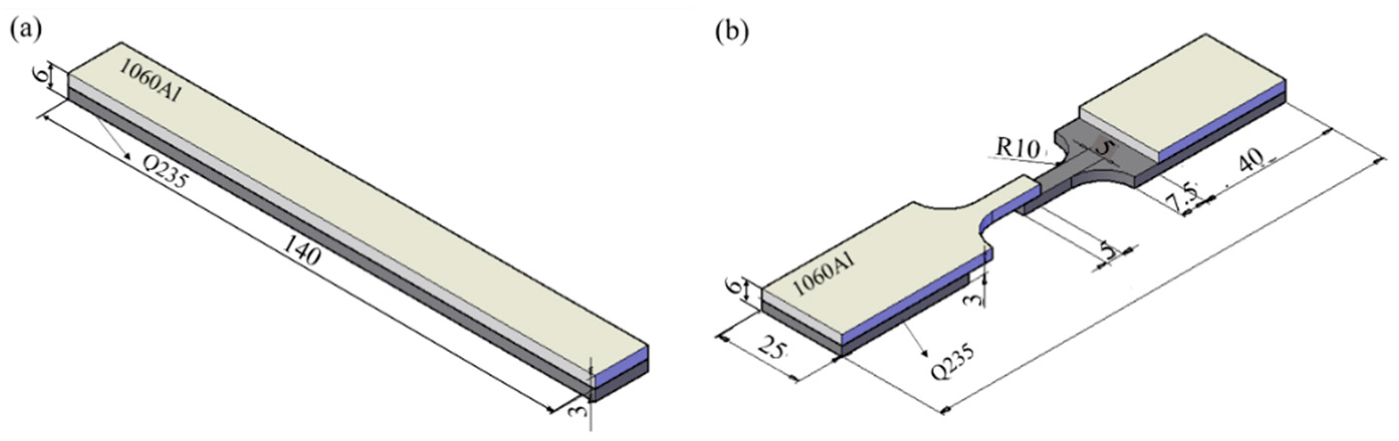
Figure 1.
Dimensions of mechanical samples: (a) bending specimen and (b) shear specimen (unit: mm).
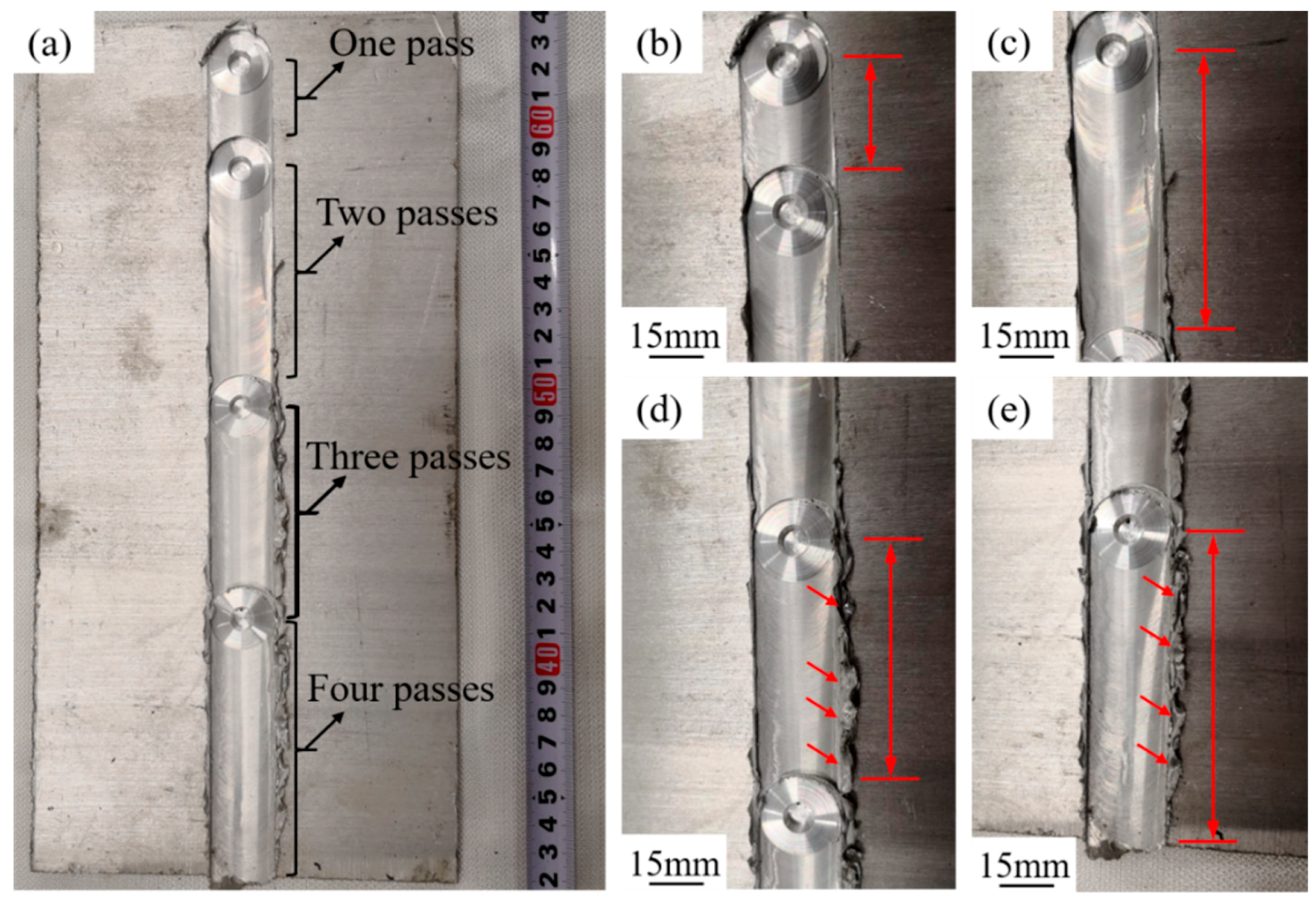
Figure 2.
1060Al/Q235 composite plate after multi-pass friction stir processing (M-FSP) with different passes: (a) 1060Al/Q235 composite plate after M-FSP; (b) single pass; (c) two passes; (d) three passes; (e) four passes.
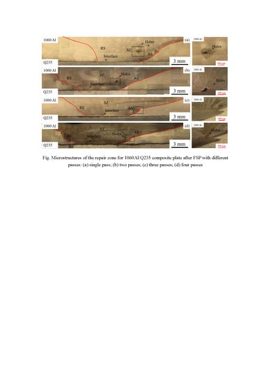
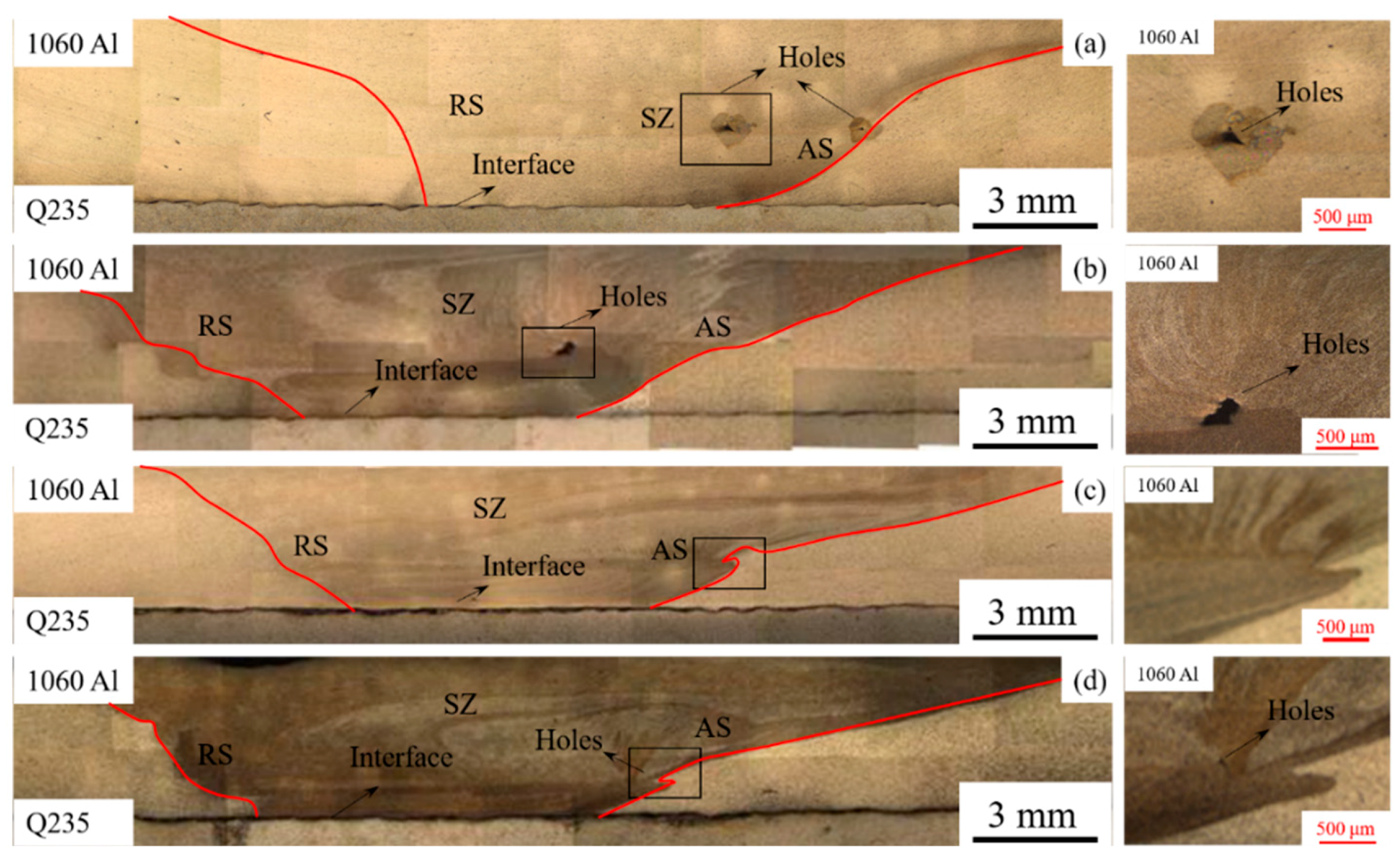
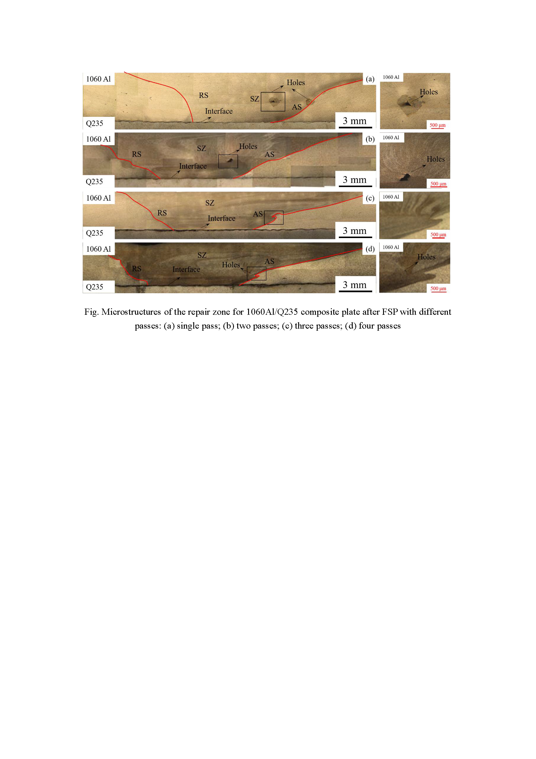
Figure 3.
Microstructures of the repair zone for 1060Al/Q235 composite plate after M-FSP with different passes: (a) single pass; (b) two passes; (c) three passes; (d) four passes.
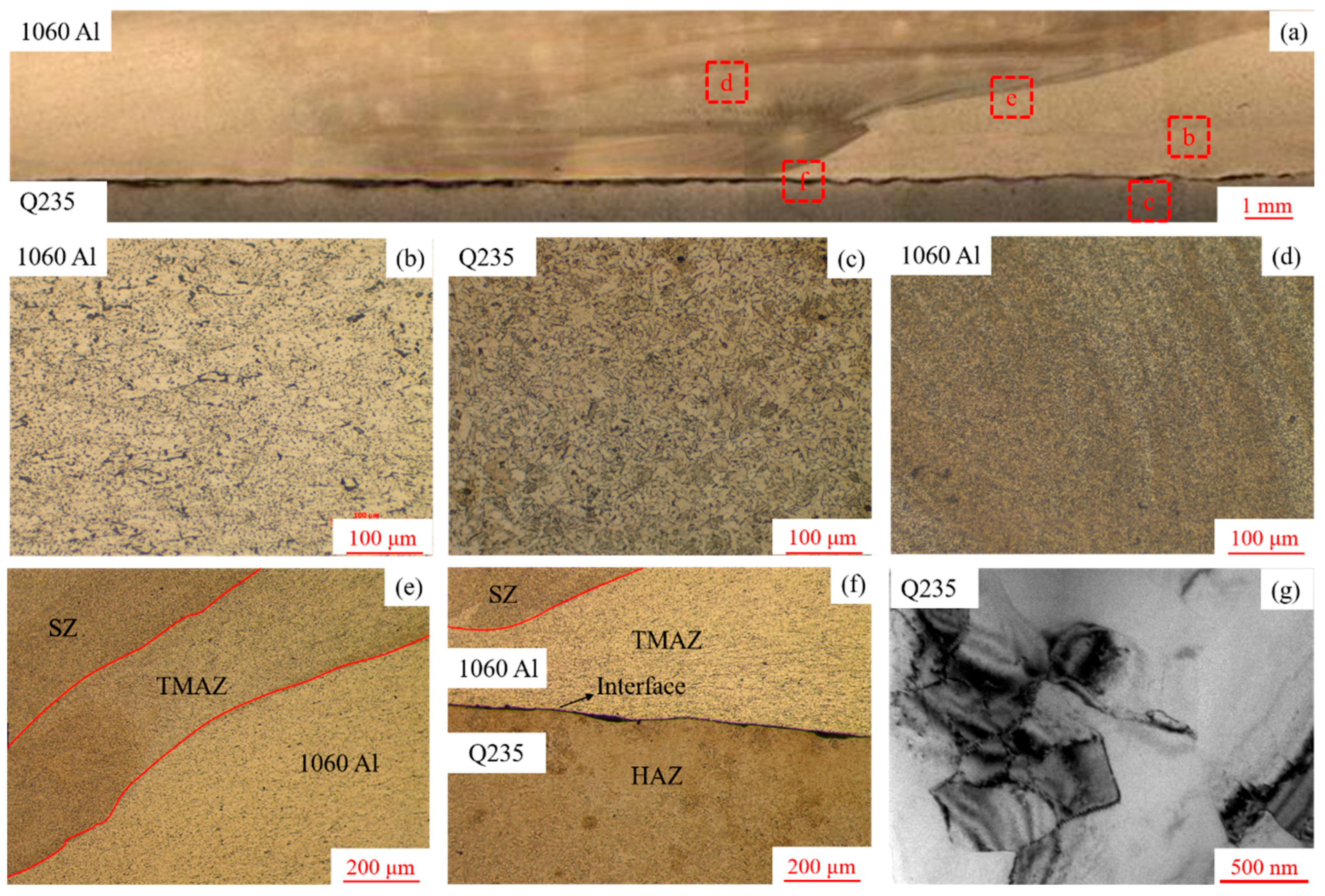
Figure 4.
Microstructures of composite plate after friction stir processing (FSP) with different passes: (a) repair zone; (b) base metal (BM) of aluminum; (c) BM of steel; (d) stirring zone (SZ); (e) thermo-mechanical affected zone (TMAZ) in the aluminum side; (f) heat affected zone (HAZ) in the steel side and (g) transmission electron microscopy (TEM) image near the interface.
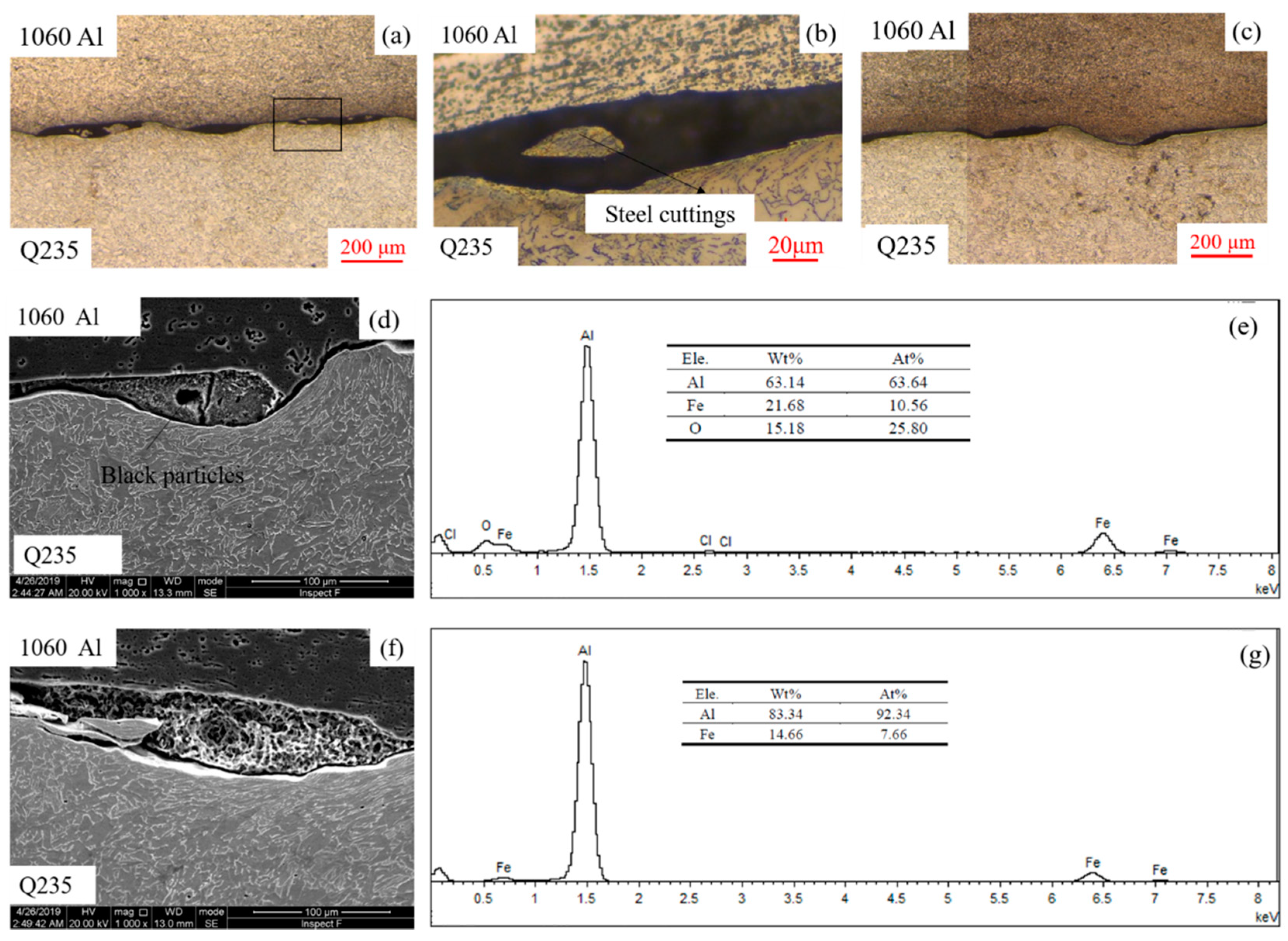
Figure 5.
Comparisons between the unrepaired interface and the repaired interface: (a) and (b) unrepaired interface; (c) repaired interface; (d) and (e) Scanning Electron Microscope (SEM) and Energy Dispersive Spectroscopy (EDS) analysis of the unrepaired interface; (f) and (g) SEM and EDS analysis of the repaired interface.
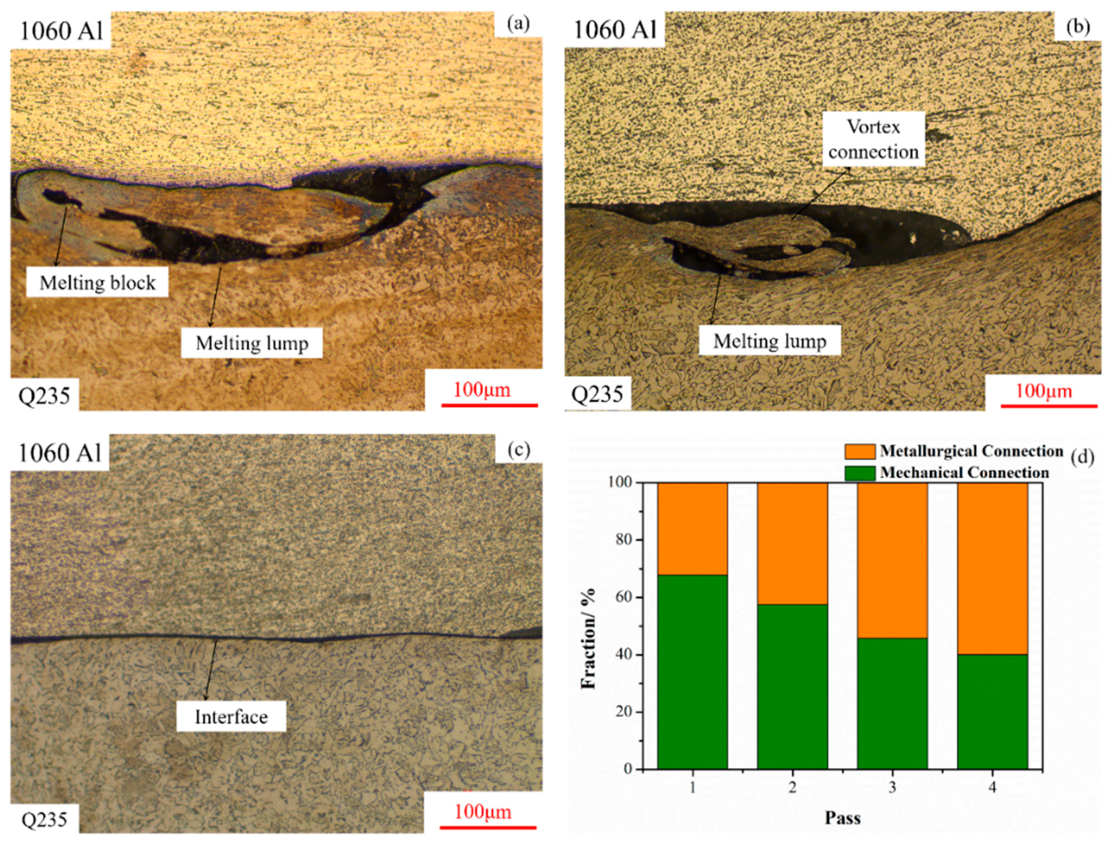
Figure 6.
Interface connection mechanism of composite plate: (a) hook connections; (b) vortex connections; (c) metallurgical bondings; (d) Fractions for mechanical connections and metallurgical bondings to the interface of composite plate after FSP with different passes.
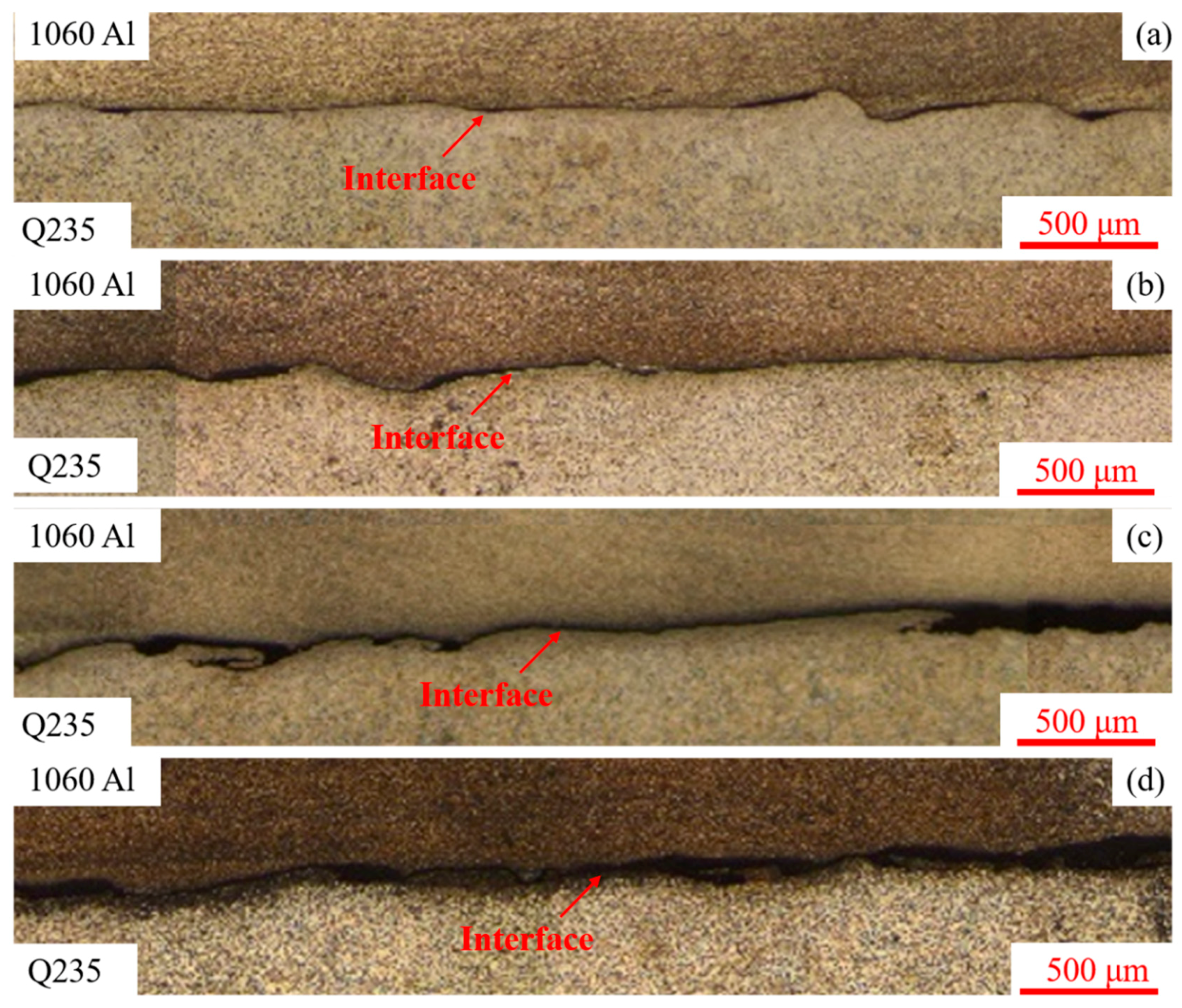
Figure 7.
Interfaces of composite plate after FSP with different passes: (a) single pass; (b) two passes; (c) three passes; (d) four passes.
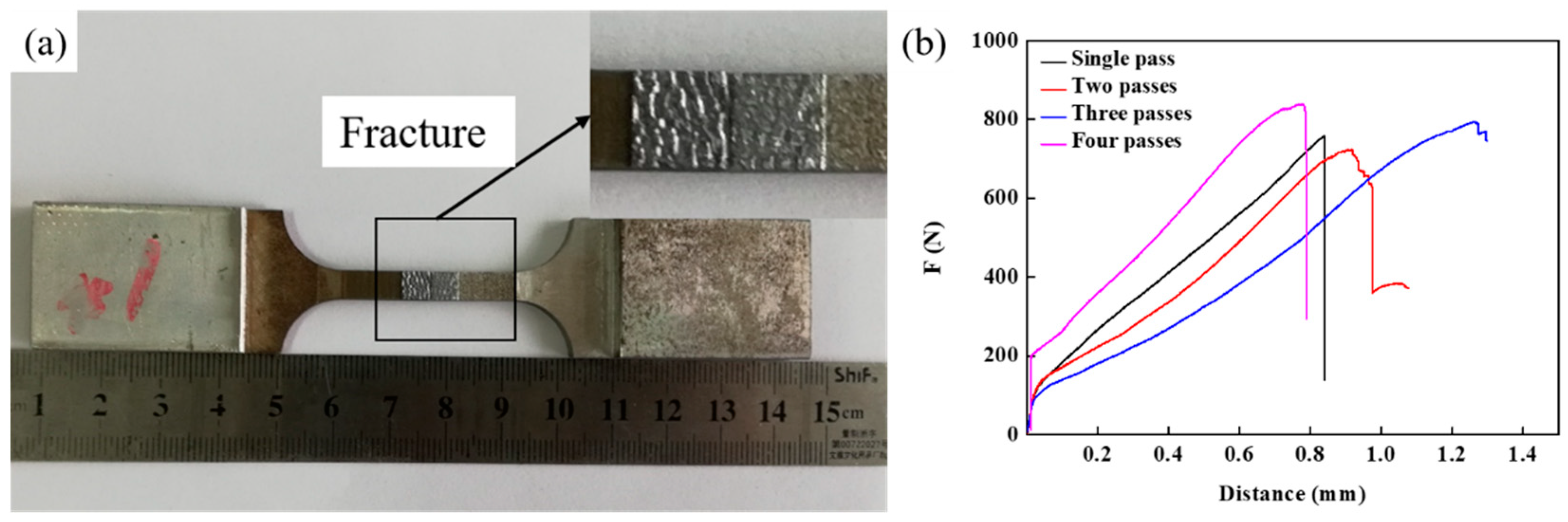
Figure 8.
Fracture morphologies and strength of shear specimens: (a) fracture morphologies of shear specimens; (b) mechanical property curves of shear specimens.
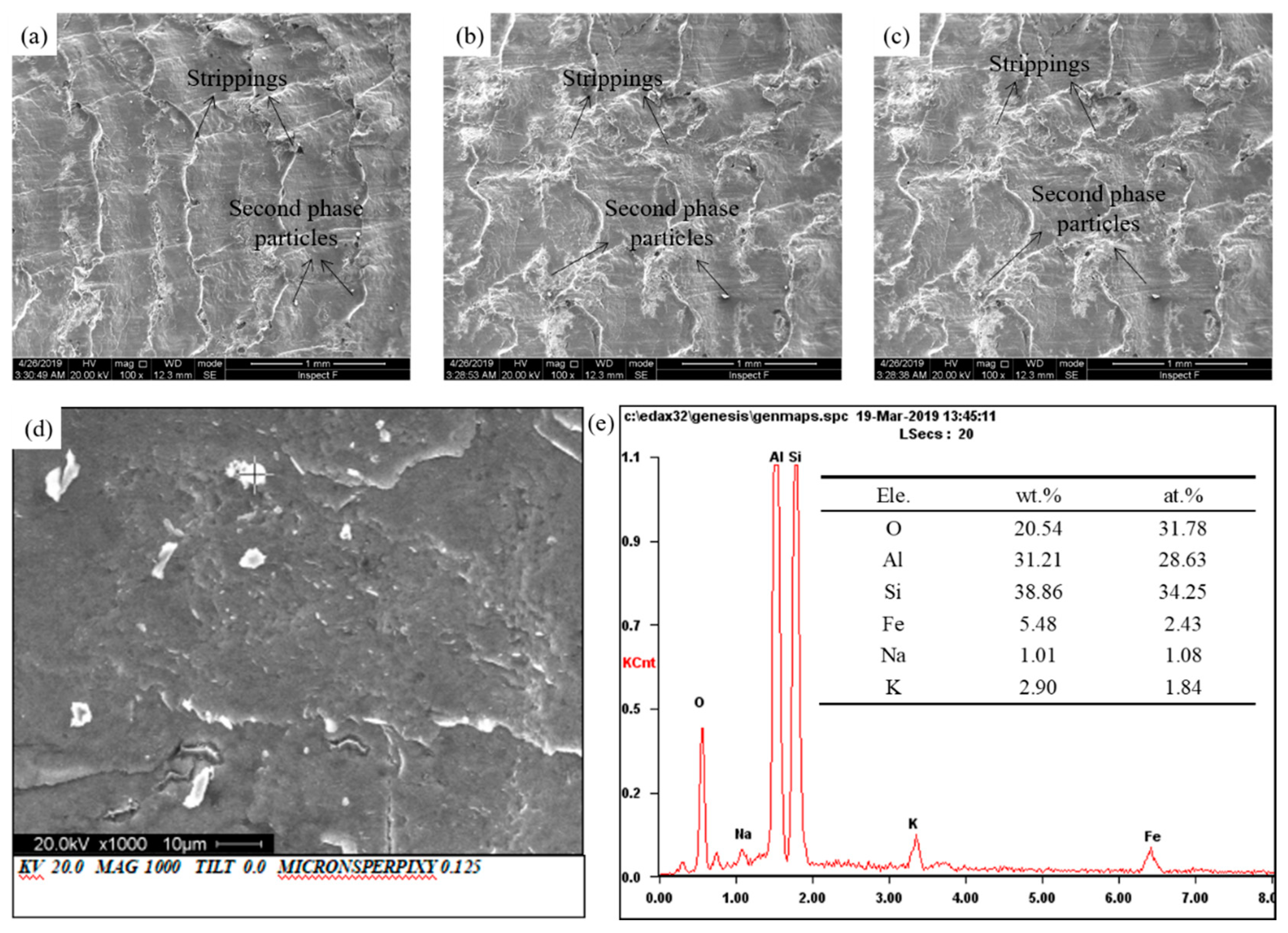
Figure 9.
Scanning electron microscope (SEM) analysis of shear specimens: (a) single pass; (b) two passes; (c) three passes; (d) and (e) SEM and Energy Dispersive Spectroscopy (EDS) analysis of second phase particles.
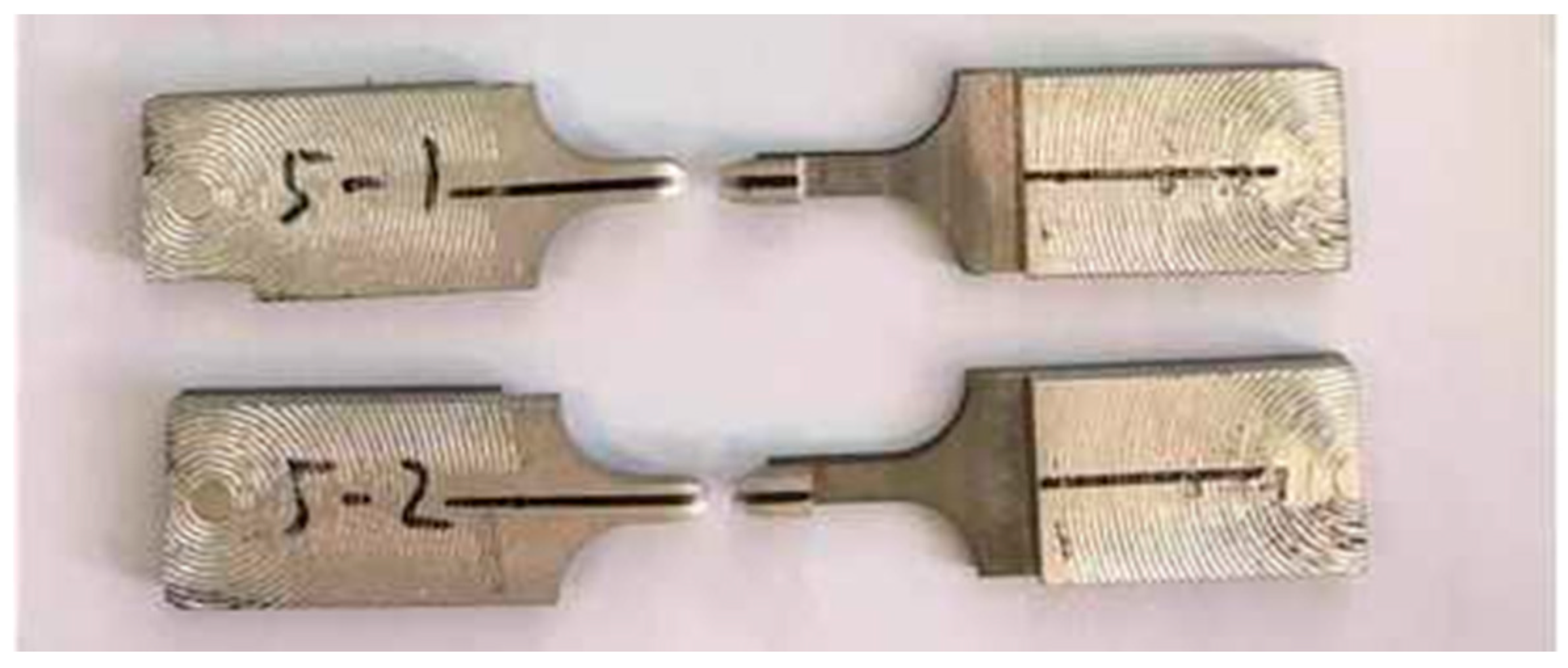
Figure 10.
Shear specimens of BM.
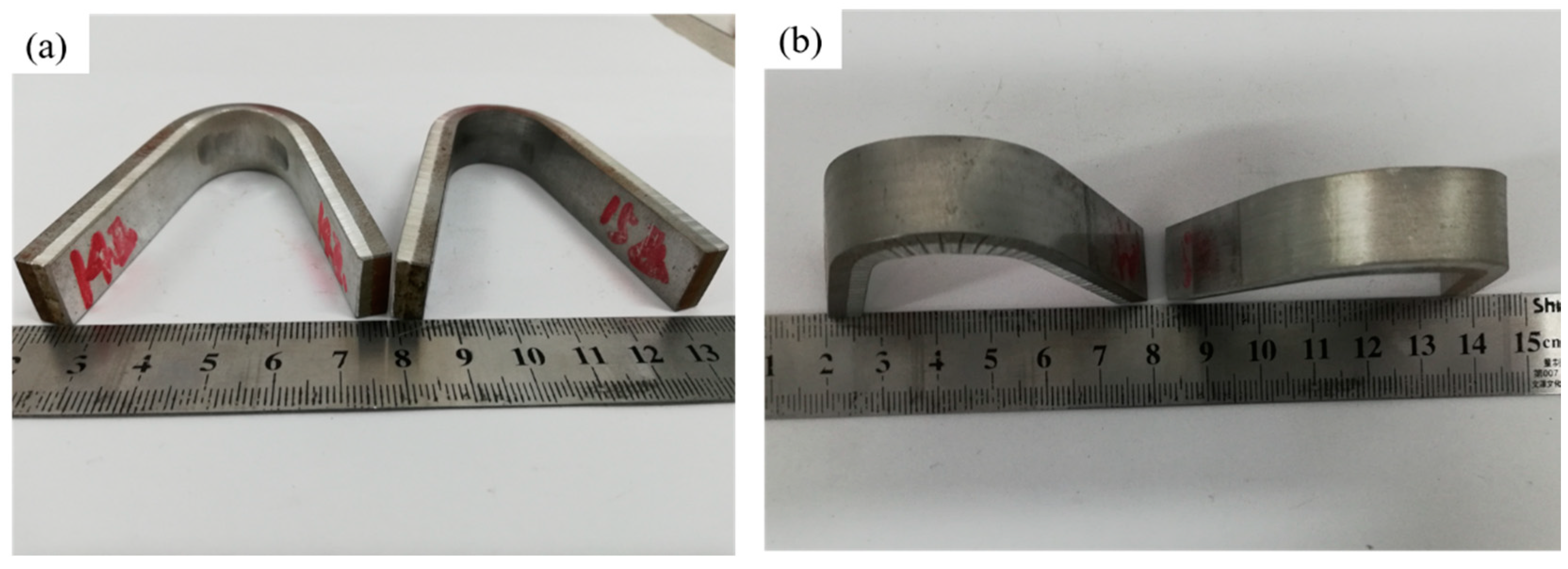
Figure 11.
Bending specimens of composite plate after FSP with two passes: (a) compressed face; (b) tensile face
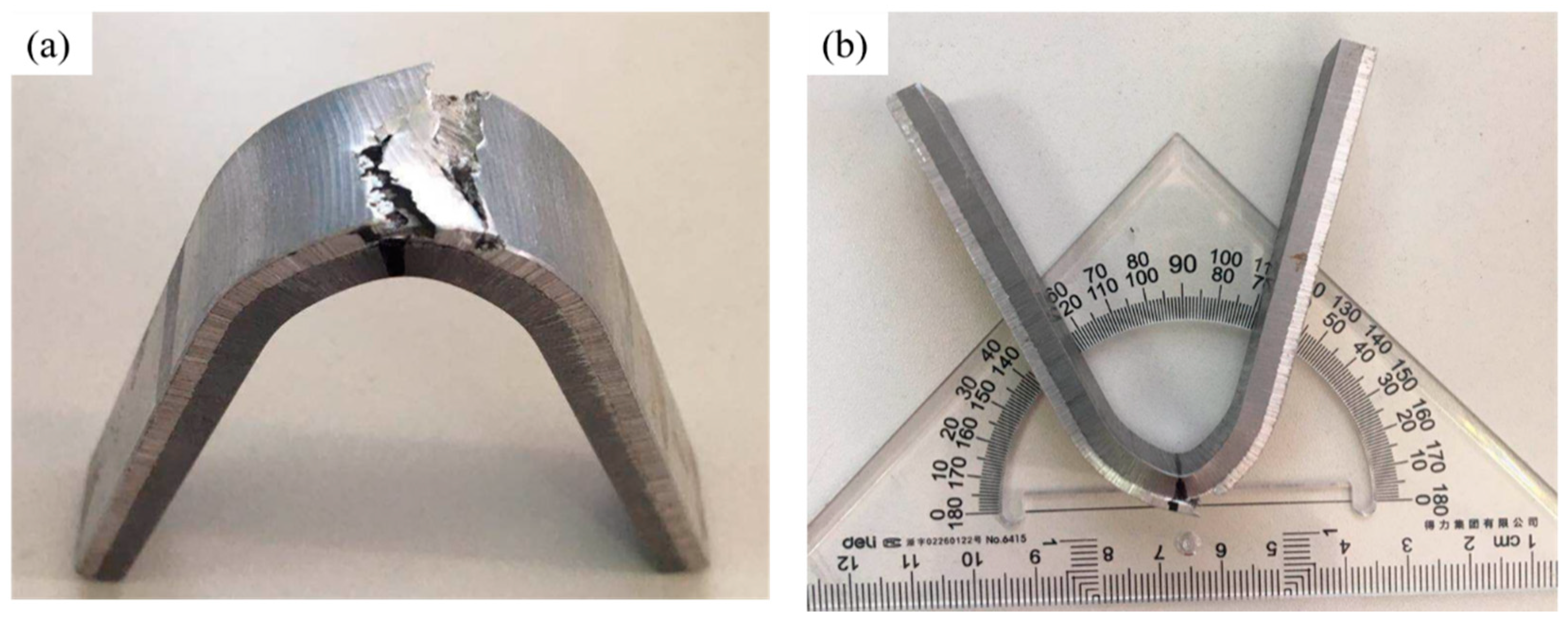
Figure 12.
Bending specimens of composite plate after FSP with four passes: (a) tensile face; (b) bending diagram of angle measurement.
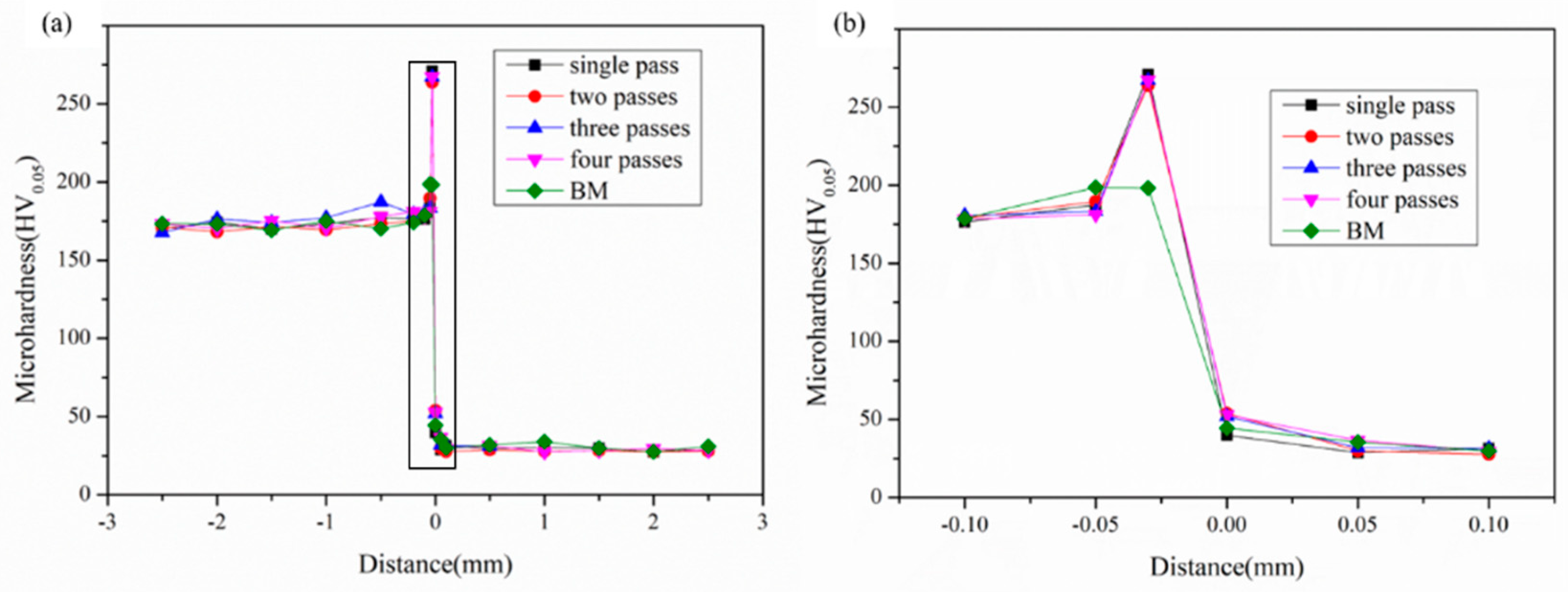
Figure 13.
Microhardness of composite plate after FSP with different passes: (
a) hardness of whole specimens; (
b) hardness for the samples near the interface (partial enlargement of
Figure 13a).
Figure 14.
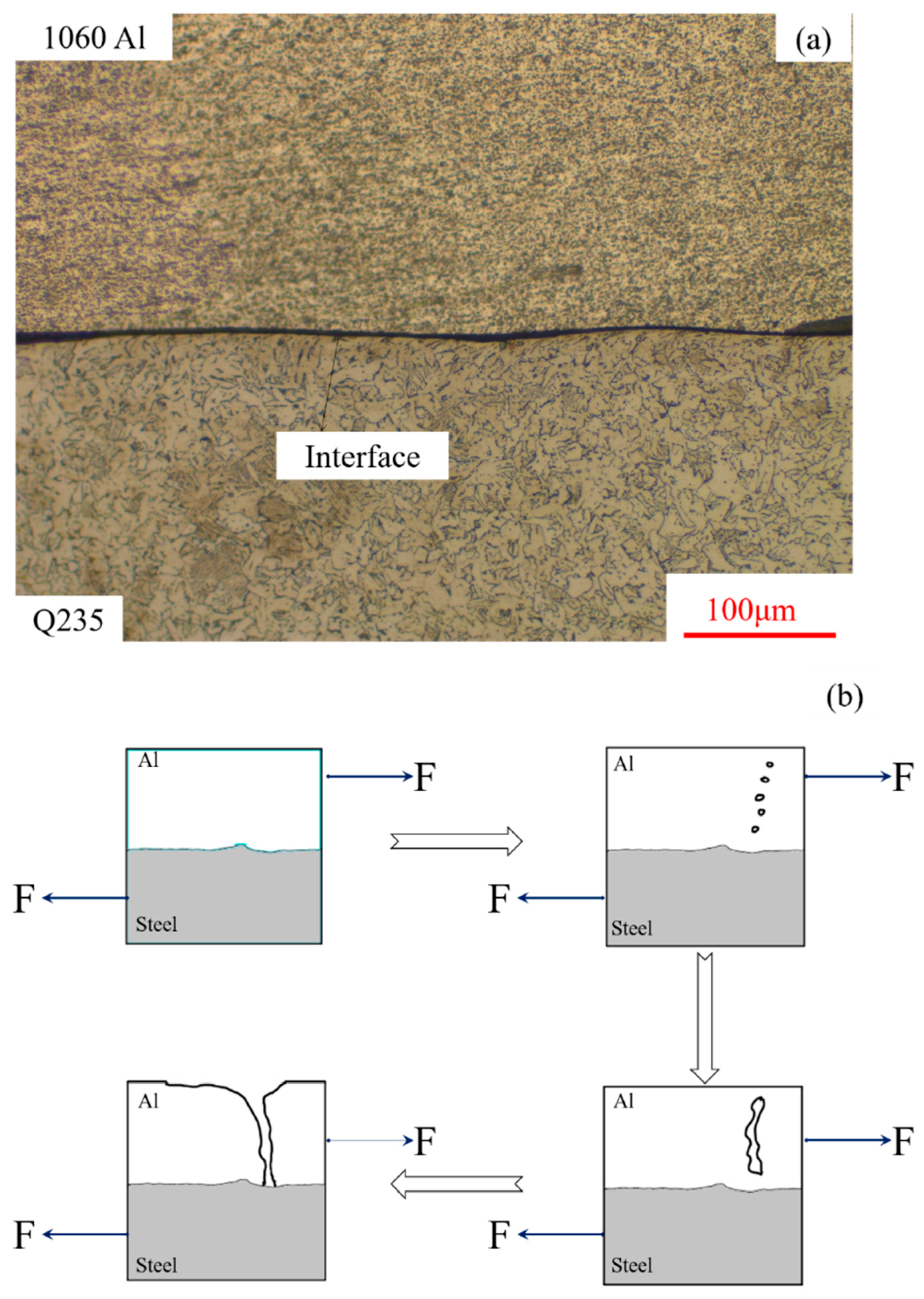
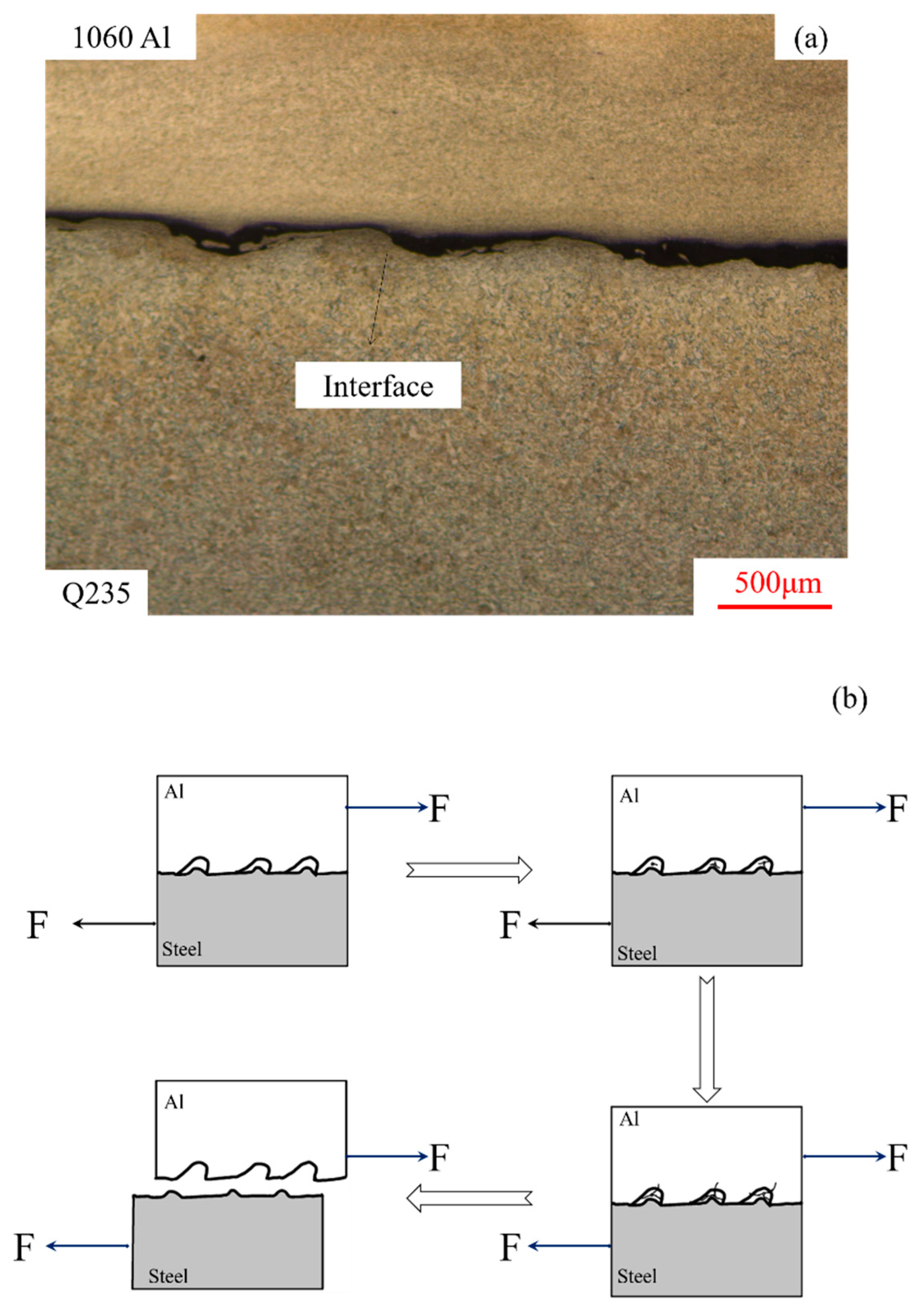
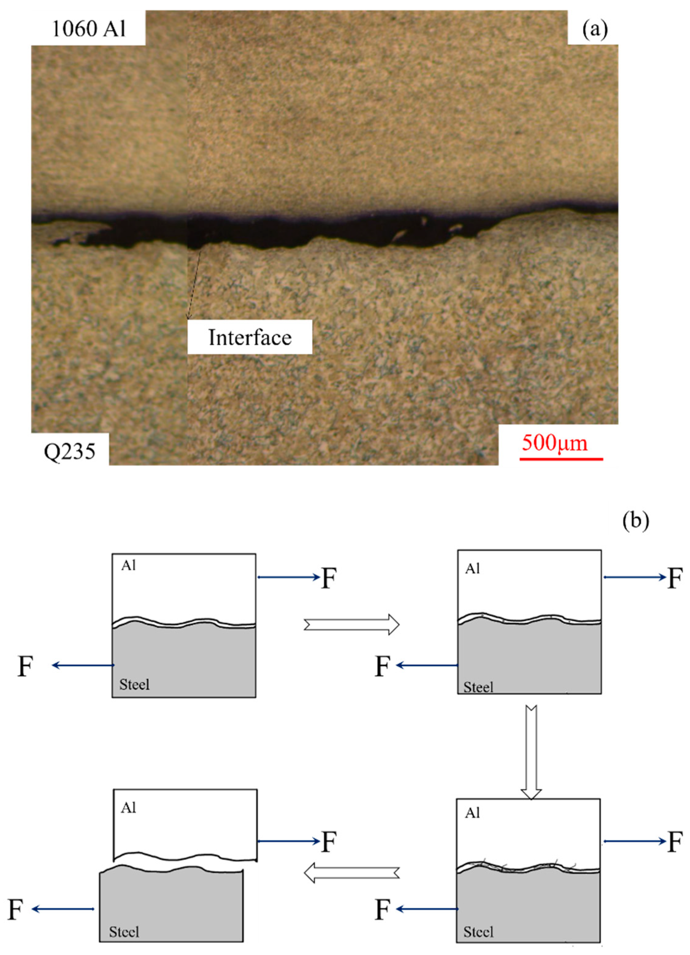
Failure mechanism of thin and flat interface: (a) physical diagram; (b) failure diagram of flat interface.
Figure 15.
Failure mechanism of thick and discontinuous interface. (a) physical diagram; (b) failure diagram of flat interface.
Figure 16.
Failure mechanism of too thick and continuous interface: (a)physical diagram; (b) failure diagram of flat interface.
Table 1.
Chemical compositions for 1060Al/Q235 composite plate (unit: wt.%).
| Ele. | Fe | Al | Si | Mn | Ti | Zn | C | S | P |
|---|
| 1060Al | 0.19 | Bal. | 0.15 | 0.03 | 0.017 | 0.012 | - | - | - |
| Q235 | Bal. | 0.029 | 0.12 | 0.32 | - | - | 0.13 | 0.009 | 0.022 |
Table 2.
Quantities and area of holes in the repair zone for 1060Al/Q235 composite plate after FSP with different passes.
| Pass | Quantities of Holes | Total Area/μm2 |
|---|
| 1 | 2 | 13.2 × 10³ |
| 2 | 1 | 12 × 103 |
| 3 | 0 | 0 |
| 4 | 1 | 1.1 × 10³ |
Table 3.
Shear strength of samples after FSP with different passes.
| Pass | S (mm2) | Force (N) | τ (MPa) |
|---|
| 1 | 25.10 | 793.6 | 31.62 |
| 2 | 25.05 | 723.4 | 28.87 |
| 3 | 24.90 | 829.5 | 33.31 |
| 4 | 25.13 | 838.6 | 33.37 |
Table 4.
Results of bending test of composite plate.
| Pass | Crack in Steel (Tensile Face) | Crack in Aluminum (Compressed Face) | Crack in Steel (Compressed Face) | Crack in Aluminum (Tensile Face) |
|---|
| 0 | No | No | No | No |
| 1 | No | No | No | No |
| 2 | No | No | No | No |
| 3 | No | No | No | No |
| 4 | No | No | No | Yes |
© 2020 by the authors. Licensee MDPI, Basel, Switzerland. This article is an open access article distributed under the terms and conditions of the Creative Commons Attribution (CC BY) license (http://creativecommons.org/licenses/by/4.0/).


