Article

Simulation of Adiabatic Shear Bands in Orthogonal Machining of Ti6Al4V Using a Rigid-Viscoplastic Finite Element Analysis

by
Orestis Friderikos
1,2,*,
Dimitrios Sagris
2,
Constantine N. David
2,* and
Apostolos Korlos
3
1
LMT, ENS-Paris-Saclay, CNRS, Université Paris-Saclay, 61, Avenue du Président Wilson, F-94230 Cachan, France
2
Mechanical Engineering Department, Laboratory of Manufacturing Technology & Machine Tools, International Hellenic University, GR-62124 Serres Campus, Greece
3
Industrial Engineering and Management Department, International Hellenic University, GR-57400 Thessaloniki Campus, Greece
*
Authors to whom correspondence should be addressed.
Metals 2020, 10(3), 338; https://doi.org/10.3390/met10030338
Submission received: 31 January 2020 / Revised: 23 February 2020 / Accepted: 25 February 2020 / Published: 3 March 2020
(This article belongs to the Special Issue Application of FEM-Simulation in Metal Forming)

Abstract

:
Catastrophic shear instability is the dominant mechanism during orthogonal cutting of Ti6Al4V. Chip segmentation even at low speeds testifies to the emergence of some kind of instability during plastic deformation of the material. Among the theoretical models, catastrophic thermoplastic slip is proposed as a mechanism to explain the destabilization of homogeneous plastic deformation, which results in localized, band-like adiabatic shear deformation. On the other hand, fracture models which consider machining as a mechanism of ductile or brittle fracture are used to explain the segmented chip formation as a periodic crack generation mechanism. This work aims at elucidating the fundamental mechanisms of the above theoretical models using a coupled thermomechanical rigid-viscoplastic FEM analysis. Introducing an energy criterion for ductile damage, numerical results showed that failure within the adiabatic shear band (ASB) is a post-localization mechanism occurring after intense shear localization. Simulations revealed a void initiation and coalescence mechanism which resembles an array of discontinuous degraded elements of nearly ellipsoidal shapes that grows and progressively coalesces forming a macro crack inside the ASB. Several aspects of ASB formation are addressed, among others, the micro-scale spatial temperature profile, parametric studies of critical damage energies, chip segmentation frequency, etc. Experimental results of ASB formation pertaining to chip morphology and cutting forces are compiled and analyzed to evaluate the FEM model at the low speed regime.

1. Introduction

Catastrophic shear instability in orthogonal cutting of Ti6Al4V causes localized material failure within the primary shear zone which gives rise to segmented chip formation. Different theoretical foundations have been proposed to explain the catastrophic shear instability but the mechanism has not been well established so far. Among them, thermally aided shear instability was first proposed by Zener and Hollomon [1], introducing the term ‘Adiabatic Shear Band’ (ASB). The authors observed this type of instability by using a standard type die to form a punching in a low carbon steel plate. High temperature was attained due to the concentration of shear strain which is typical for high speed shear deformation. Furthermore, Recht formulated a primary criterion for the catastrophic slip in a shear zone based on the thermophysical response of the work material involving strain hardening and thermal softening [2]. From another theoretical viewpoint, fracture inside the shear zone has been proposed as an alternative mechanism of segmented chip formation. The periodic crack formation theory has been used to explain the chip formation during the machining of hard steel. According to this theory, fracture exists in all types of chip formation, even in continuous chips. Detailed information is provided in [3,4,5,6,7].
Under certain conditions, high strain rate plastic deformation may occur along with the formation of ASB. Material thermal softening may destabilize the homogeneous plastic deformation if it outweighs strain and strain rate hardening. These narrow zones of very large shear strain initiate and propagate in a previously homogeneous deformed region. ASB width may be of the micron range (10–100 μ m), whereas the lateral extension may be hundreds or even thousands of times bigger. In titanium alloys, adiabatic shear banding is further enforced by the low value of the heat conductivity (≈16 W/mK). ASBs have a substantial effect in high speed deformation and significantly alter the mechanical behavior of the material in question. In many cases ASBs are often precursors to further damage and provide initiation sites and propagation paths for cracks. A thorough overview of the underlying physics and mathematical foundations of ASB can be found in [8,9].
The dynamic behavior of Ti6Al4V can be comprehended taking into account its crystalline structure. Ti6Al4V consists of two crystalline phases; a low temperature α phase (hcp) and a high temperature β phase (bcc). The hcp lattice structure exhibits a restricted number of slip systems on the prismatic planes compared to bcc. By increasing temperature, titanium undergoes an allotropic transformation from an hcp to bcc structure between 800 and 850 C ( β transus temperature). Therefore, local deformation is enabled wherever the structure has transformed to bcc.
Komanduri proposed that the allotropic transformation of the α phase can localize shear and cause instability in the primary zone [10]. Therefore, the chip morphology changes from discontinuous at low cutting speeds to segmented but continuous at high cutting speeds. Rogers [11] has given an overview of the general phenomenon including the microstructures resulting from localized flow. Rogers and Shastry [12] studied a crystallographic phase change in ferritic steels which leads to the formation of transformed adiabatic shear bands normally preceded by deformed shear bands. This phase change happens if the conditions of dynamic deformation are sufficiently severe, i.e, the rate and magnitude of the deformation are sufficiently great. Timothy and Hutchings investigated the structure of adiabatic shear zones in Ti6Al4V with different parent microstructures resulting from ballistic impact of steel spheres [13]. Furthermore, Landau et al. reported thorough microstructural characterizations that clearly show the gradual character of the ASB phenomenon, best described as a nucleation and growth failure mechanism, and not as an abrupt instability [14]. Sutter and List [15] conducted orthogonal cutting tests on a specific ballistic set-up to study the change in morphology and mechanism of chip formation of Ti6Al4V. More recently, Navarro et al. [16] explored the pattern of multiple shear bands in AISI 4340 steel using the Thick-Walled Cylinder method.
Numerical studies of ASB formation in machining have been performed by numerous research groups. Among them, Komanduri and Hou [17] developed a thermal model for the thermoplastic shear instability in the machining of Ti6Al4V based on the analysis of the shear-localized chip formation process and the temperature generated in the shear band due to various heat sources. Molinari et al. [18] investigated the role of cutting conditions on adiabatic shear banding and chip serration by combining finite element calculations and analytical modeling. Shivpuri et al. [19] presented a numerical model which incorporates material changes into the phenomenological behavior of the chip using a ductile damage criterion. Baker [20] used a two-dimensional FEM model of the chip formation process for a parametric study of a phenomenological material flow stress equation of titanium alloys. Calamaz et al. [21] introduced a constitutive law with strain softening to analyze chip segmentation of Ti6Al4V.
In this work a rigid viscoplastic FEM analysis is used to simulate ASB evolution in orthogonal machining (Figure 1). This cutting process provides a remarkable advantage for FEM simulations of ASB due to the localized shear formation within the primary shear zone (a priori known). Two simulation approaches have been investigated in this analysis. At the first simulation model, only catastrophic thermoplastic slip is considered. Therefore, simulation of ASB is caused similar to Recht’s mechanism of catastrophic thermoplastic shear. Additional models including ductile damage are implemented to investigate the major aspects of the failure process, identifying the ASB propagation mechanism. Thus, simulations are able to identify the possible nucleation and growth of voids and/or microcracks inside the ASB. A direct comparison of the two approaches provides insight into the fundamental physics of ASB formation.
In rigid viscoplastic FEM analysis, the severe mesh distortion owing to extremely large deformations involving considerable remeshings during the solution process, which introduces numerous difficulties. A major concern is the need to project and interpolate between meshes in successive stages, which may lead to degradation of the solution accuracy and software complexity, not to mention the burden associated with a large number of remeshings. To this end, interest has been shifted to meshless methods [22]. We should refer among others the work of Oden and Duarte who employ the partition of unity in a meshless setting in the context of the hp-cloud method [23], the Generalized Finite Element Method (GFEM) based on the partition of unity of Babuska and Melenk [24], the smooth particle hydrodynamics (SPH) [25], and the reproducing kernel particle method (RKPM) [26,27].
Note that only general information is cited in this introduction. A more detailed literature survey will be given in each section. The organization of the paper is as follows: In the next section, the basic principles of the rigid viscoplastic formulation are reviewed and details of the numerical method are discussed. Section 3 concerns the numerical investigation of ASB formation under the thermally aided shear instability concept where an insight of the basic mechanisms during one cycle of chip formation is revealed. A ductile damage model is introduced in Section 4 to directly compare the synergetic effect of the thermally aided shear instability with ductile damage on the ASB formation. Numerical results concerning micro-scale phenomena within the ASB are presented in Section 5. In Section 6, the experimental approach for the orthogonal cutting experiments is described and results of the chip segmentation mechanism are presented. Finally, a synopsis of the most important remarks and open problems are reviewed in Section 7.

2. FEM Modeling of High Speed Material Processing

2.1. Rigid-ViscoPlastic Formulation

Numerical modeling of orthogonal machining is a challenging task due to thermomechanical coupling, temperature and rate-dependent material properties, non-linear boundary conditions (friction), heat transfer, conversion of plastic work to heat, shear localization, etc. In this work, a Rigid-ViscoPlastic (RVP) formulation is used to simulate the shear instability using the FEM code Deform-2D [28]. The RVP FEM have been used in numerous non-steady state metal forming processes, utilizing basically the same mathematical principle as that of the upper bound method. In this formulation, the elasticity effects are not considered, i.e., the additive decomposition of the total strain-rate tensor ε ˙ i j = ε ˙ i j e + ε ˙ i j p simplifies to ε ˙ i j = ε ˙ i j p , where ε ˙ i j e is the elastic component of the strain-rate tensor, ε ˙ i j p is the plastic component and ε ˙ i j is the total strain-rate tensor. This idealization is based on the fact that elastic components of strain remain small as compared with irreversible strains. The RVP formulation turns out to be similar to fluid flow problems and it is also called as flow formulation [29]. While it is not possible to calculate the residual stresses and the spring-back effect, the flow formulation presents significant advantages. Unlike the elasto-plastic FEM, however more approximate, the RVP formulation is simpler to implement in computer codes, more stable and can use relatively larger time increments, thus improving the computational efficiency. In RVP analysis, stresses relate directly to rate of deformation tensors or infinitesimal strain rates. An overview of the foundation theory and many interesting results can be found elsewhere [30,31].

2.1.1. Weak Form

In the RVP approach, the problems are considered as quasi-static and the infinitesimal theory is applied. We assume an isotropic plastically deforming body occupying a domain Ω R 2 . The domain Ω and its associated boundary Ω represent the current configuration of a body according to the Updated Lagrangian (UL) formulation. A variational form of the boundary value problem is used to find a kinematically admissible velocity field, stated as an integral form. The essence of the variational formulation is to calculate the total potential of a scalar quantity Φ of the system (functional), and to invoke the stationarity of Φ , i.e., δ Φ = 0 with respect to arbitrary changes of the state variables. If we assume a body Ω of a rigid-viscoplastic deforming material, the functional Φ (energy rate) is defined by an integral form
Φ ( v ) = Ω σ ¯ ε ¯ ˙ d V Ω F F i v i d S
where σ ¯ is the effective stress, ε ¯ ˙ is the second invariant of the strain-rate ε ˙ i j called effective strain-rate, v i are velocity components, and Ω F is the part where the traction conditions are imposed in the form of nodal point forces F i (natural boundary conditions). The above expression is in accordance with the virtual work-rate principle where the first term in the right of Equation (1) represents the internal deformation work-rate, whereas the second term represents the work-rate done by the external forces. F i represents prescribed surface tractions on the boundary surface Ω F .
Recalling the Marcov-Hill variational principle, among all virtual (admissible) continuous and continuously differentiable velocity fields v i satisfying the conditions of compatibility and incompressibility in Ω , as well as the velocity boundary conditions on Ω , the real velocity field gives to the functional Φ a stationary value, which means that the first order variation of Φ vanishes (i.e., δ Φ = 0 ). In order to meet the incompressibility constraint condition ε ˙ v = ε ˙ k k = 0 , a penalized form of incompressibility is used:
δ Φ = Ω σ ¯ δ ε ¯ ˙ d V + 1 2 Ω K ε ˙ v δ ε ˙ v d V Ω F F i δ v i d S = 0
where K is a large positive constant which penalizes the dilatational strain-rate component ε ˙ v .
In most non-stationary metal forming applications, the UL incremental procedure is used. Deformation is analyzed in a step-by-step manner in which the geometry is updated with time. The process is considered as quasi-static during each incremental deformation. When each iteration has converged, the deformed configuration after the time increment Δ t is obtained by updating the node coordinates
t + Δ t x i = t x i + v x ( i ) Δ t
t + Δ t y i = t y i + v y ( i ) Δ t
where x i , y i are the coordinates of node i, ( i = 1 , 2 , , N ) and v x ( i ) , v y ( i ) are the velocity components of node i in x and y direction, respectively. Provided that the increment of time between two adjacent referential configurations is small enough, the effective strain can be updated approximately as follows,
t + Δ t ε ¯ = t ε ¯ j + ε ¯ ˙ j Δ t
where j refer to the element number ( j = 1 , 2 , , M ) .

2.1.2. Heat Equation

The temperature distribution in the continuum can be obtained by soving the energy balance equation:
k 2 T + β σ ¯ ε ¯ ˙ ρ c T ˙ = 0
where k is the thermal conductivity, β is a coefficient which presents the fraction of the deformation energy dissipated into heat, σ ¯ ε ¯ ˙ represents the work heat per unit volume due to plastic deformation, and ρ c is the volume specific heat of the material.
The variational form of Equation (6) is
Ω k 2 T δ T d V + Ω β σ ¯ ε ¯ ˙ δ T d V Ω ρ c T ˙ δ T d V = 0
By using the divergence theorem
Ω k T δ ( T ) d V + Ω ρ c T ˙ δ T d V Ω β σ ¯ ε ¯ ˙ δ T d V Ω q q n δ T d S = 0
where
q n = k ϑ T ϑ n
is the heat flux across the boundary surface Ω q , and n denotes the unit normal to the boudary surface.
Transfer of energy during forming operations is a complex process since the mechanical behavior of the continuum depends on the thermal properties of the material and the thermal behavior depends on its mechanical properties. At the same time, heat is transferred through the boundaries of a deforming body and heat is also generated by dissipative mechanisms. The resulting temperature changes in the continuum, in turn, affect the material response to the imposed deformation. In the FEM code, the thermo-viscoplastic coupled analysis is achieved by combining the heat transfer with deformation analysis in a so-called loose sense [32,33].

2.2. Remeshing and Adaptive Meshing

A limitation of the Updated Lagrangian method for large deformation problems is the excessive element distortion which leads to unacceptably small time steps and numerical instabilities. An avenue to simulate unconstrained plastic flows is to use a remeshing process. During simulation, an automatic mesh generation engine is activated in the case of zero or negative determinant of the Jacobian matrix, or on assignment of user defined criteria [28]. The simulation is interrupted and a new mesh is calculated conforming to the current state of the geometry. Nevertheless, there is a substantial cost associated with frequent remeshing since it smoothens the state variable fields. This is due to the inherent uncertainty in preserving the state variables in the remapping process and to cumulated remapping errors.
The use of adaptive meshing is well suited to handle the multiscale nature of ASB by resolving steep gradients in the solution. Mesh adaptivity leads to a considerable reduction in the number of degrees of freedom and helps to achieve high accuracy without increasing the computational resources. Weighting factors can be used to control the relative mesh density at regions of high curvature or of steep strain, strain rate and temperature gradients [28]. Thus, a high quality mesh in the primary shear zone is maintained where the ASB initiate and propagate. Figure 2 shows the mesh adaption during the ASB formation using a minimum mesh size of h m i n 0.4–1.6 μ m and a maximum element size ratio of 15.
Despite the advances of mesh generation algorithms, meshing is still an open problem for the simulation of ASBs as their formation and evolution are sensitive to the mesh size. Besides, the implementation of damage models into the FEM analysis suffers from mesh sensitivity (size and alignment). A direct consequence is that decreasing the mesh size does not lead to converged results. During the thermomechanical calculations, the length scale of the mesh regulates the spatial evolution of the state variables. An understanding of the implications of minimum length scales is crucial for the convergence and efficiency of numerical computations [34]. In order to resolve the physical and constitutive features of the material, the element size must be below (at least) the ASB bandwidth. An a priori estimation of the mesh is not an easy task as it is strongly dependent on the underlying physics of the problem. Approaches to decrease mesh dependence for shear bands can be found elsewhere [35,36].

2.3. FEM Model, Material Flow Stress, Thermomechanical Properties and Boundary Conditions

For the numerical investigations, a 2D plane strain model is used due to the small gradients of the state variables in the direction parallel to the cutting edge. The workpiece is designed as a rectangular block with large enough dimensions to reduce the boundary conditions effects. All degrees of freedom of the tool are constrained. At the left and bottom boundary nodes of the workpiece, a prescribed velocity is imposed in the horizontal direction while they are constrained in the vertical direction. An adaptive mesh refinement with a minimum mesh size of h m i n 0.1–1.6 μ m is generated in the region of intense shearing to provide high resolution of the state variables. This results in a total number of from 25,000 up to 27,000 four-node quadrilateral elements. The workpiece is modeled as rigid-viscoplastic, homogeneous, with a constitutive relation which obeys the J 2 flow theory of plasticity with isotropic hardening. The tool is designed with a zero rake angle ( γ = 0 ) and is modeled as rigid. In comparison with the large plastic deformation of the workpiece material, the tool elastic deflection can be neglected without affecting simulation results. The tool edge radius is considered perfectly sharp to avoid frequent remeshings due to master-slave inter-penetrations.
The accuracy of flow stress models have a significant impact on simulations in high strain-rate deformation. In conventional high-speed deformation tests, such as the Split-Hopkinson-Pressure-Bar, the test specimens are subjected to maximum strains of 0.5 and strain rates in the range of 10 2 –10 4 s 1 [37]. On the contrary, in machining, the strains in the primary zone are higher than 1 while the stain-rates vary in the range of ϵ ˙ = 10 3 10 7 s 1 or even higher which are far beyond the experimental obtained tests. Thus, in numerical simulations, the material behavior is often extrapolated over several orders of magnitude. In this work, a flow stress equation is defined as a function of strain, strain-rate and temperature σ ¯ ( ε ¯ , ε ¯ ˙ , T ) [38] (included in the material database of Deform-2D [28]).
An important factor related to ASB physics is the thermomechanical conversion of mechanical energy expended during plastic deformation into heat, also known as the Taylor–Quinney coefficient β [39]. Since thermal evolution is crucial for ASB initiation and growth, an accurate knowledge of the coefficient β is important to obtain reliable FEM results. Generally, the fraction of the plastic work converted into heat is assumed to be a constant parameter of 0.9 for most metals. Nevertheless, experimental tests of Ti6Al4V revealed that the heat fraction coefficient can be strongly dependent on strain and strain-rate, and there is no unanimous agreement on the fraction of plastic work conversion into thermal energy [40,41,42,43]. Thermodynamical foundations leading to the observed plastic strain and strain-rate dependence of β have been discussed by Rosakis et al. [44]. Thus, an interesting future research field would be to introduce a constitutive equation relating the coefficient β with strain and strain-rate.
The boundary conditions for the mechanical analysis at the tool/workpiece interface are complex and depend on various factors, i.e., cutting speed, feedrate, chemical composition of the tool and the workpiece, etc. [45]. Even though several models have been proposed to describe the friction conditions, the correlation with experimental evidence is not yet satisfactory. To the best of the author’s knowledge, there are conflicting viewpoints concerning the nature of friction conditions and definitive conclusions cannot be drawn [46]. At the present model, a shear friction law is used:
τ f = m k
k = σ ¯ 3
where m ( 0 < m 1 ) is the friction factor, k is the material shear yield stress and σ ¯ is the effective yield stress.
The boundary conditions for the thermal analysis are set to the following: A constant heat transfer coefficient of 105 W/m 2 K is assigned to the tool/workpiece interface and for the heat conduction between the workpiece and air, a heat transfer coefficient of 20 W/m 2 K is used. The workpiece and the cutting tool are initially at a uniform ambient temperature of T 0 = 25 C. Note also, that all material constants of Ti6Al4V are temperature dependent [28].

3. ASB Formation under Thermally Aided Shear Instability

3.1. Catastrophic Thermoplastic Slip

Heat generated during the dynamic deformation of materials creates temperatures and temperature gradients which can exercise significant influence upon the observed dynamic behavior. If the rate of decrease in strength, resulting from the local increase in temperature, equals or exceeds the rate of strength increase due to the effects of strain-hardening, the material will continue to deform locally. This unstable process leads to the catastrophic condition known as adiabatic slip [1]. In this theoretical framework, it is worthy to mention Recht [2] who formulated a primary criterion for the catastrophic slip in a shear zone based on the thermophysical response of the work material involving strain hardening and thermal softening. According to this criterion, the problem is expressed in terms of shear stress rather than tensile stress. The instability condition is stated as
0 τ ϵ τ θ d θ d ϵ 1
where τ , ϵ , and θ refer to the shear stress, shear strain, and temperature, respectively. If the ratio in Equation (12) is equal to unity, catastrophic slip will be imminent; if its value lies between zero and 1, the material will shear catastrophically. High positive values above unity indicate that strain-hardening is predominant and shear deformation will distribute throughout the material. Other thermoplastic instability criteria can be found in [17,47].

3.2. Numerical Investigations

In these numerical examples, simulations of ASB depend solely on the thermoplastic shear mechanism. A sequence of snapshots of the temperature, equivalent strain and equivalent stress fields during the formation of a complete chip segment are shown in Figure 3. The cutting conditions are set as: Speed v = 200 m/min, feed = 0.15 mm/rev, rake angle γ = 0 . The ASB initiation and its space–time evolution is described in the following:
At stage (a), the ASB nucleates at the vicinity of the tool tip and propagates almost straight along the primary shear zone. Within the band, shearing occurs so rapidly that heat generated from plastic work conversion cannot be quickly dissipated to the neighboring material (see stages (b) and (c)) since heat conduction is a slow process compared to the rate of plastic work conversion. Progressively, inside the ASB the resistance to continued loading becomes lower than the surrounding material and strain tends to concentrate further. The additional deformation generates more heat causing the material to become even softer. Essentially, temperature rise enforces strain localization and vice versa, further amplifying the non-uniformity in strain. Hence, the ASB becomes the weakest zone in the cutting region. At the same time, the surrounding material experience little plastic strain. As a consequence, a drop of the von Mises stress inside the ASB occurs in stages (b) and (c). This mechanism of strain localization destabilizes the homogeneous plastic deformation and triggers the formation of chip segments.
A direct comparison of the localization of selected state variables on a line perpendicular to ASB width (see Figure 4) is shown in Figure 5. A high temperature gradient across the ASB is enveloping a steeper gradient of the equivalent strain. At this simulation snapshot, the temperature rise across the shear zone is of the order of 450 C, the effective strain reaches a value of 2 and the effective strain rate is of the order of 5.5 × 10 5 s 1 . One can also observe an abrupt jump of the shear stress magnitude of 300 MPa and a local increase of the shear strain of 1.4.
While the tool advances (beyond stage c), the ASB gradually curves upwards forming an arc. Simulation reveals that when an ASB is formed, the strain continues to localize within this zone and is carried away with the chip motion. Finally, in stage (f), a new ASB nucleates in front of the tool tip (see the ASB snapshots at the first (a) and the sixth (f) stage of Figure 3) and the same mechanism will be followed for the next chip segment. The ASB can reform intermittently if the loading conditions are maintained.

4. ASB Formation Using a Ductile Damage Model

4.1. Damage Modeling

Ductile fracture has been widely studied as a process of void nucleation, growth and subsequent coalescence. There is experimental evidence that ductile fracture is also evident inside the ASB. According to experimental data of Marchand and Duffy [48], the onset of the ductile failure via shearbanding occurs in a sudden, drastic way. The same studies show that immediately following the onset of the ductile failure, the stress at the material point drops almost vertically to about a quarter of its peak value. The crucial ingredient for simulating ASB propagation is how to model the stress collapsing state of the ASB.
Metallurgical examination of the ASB and the cracking present in the localized zones in Ti6Al4V samples deformed at low, medium and high deformation speeds showed that the hardness of these zones was not significantly higher than that of the surrounding metal and that the crack morphology was also consistent with that of ductile fracture [49,50,51,52].
The necessity for the introduction of a ductile failure criterion was given by Schoenfeld and Wright [53], who identified the need of a shear damage model to predict the stress collapse state inside an ASB, as well as the need for a ductile failure criterion to determine the right timing at which it should occur. Incorporation of a damage criterion into the phenomenological viscoplastic constitutive equations permits a description of rate-dependent, inelastic deformation, and ductile fracture. Considering the history of stress and strain at plastic deformation of metals, Cockcroft and Latham [54,55] postulated that it is the principal stress, rather than the equivalent stress, which is important in fracture initiation. They proposed a fracture energy criterion where the magnitude of the maximum principal stress over the plastic strain path is taken into account
I s = 0 ϵ ¯ f σ 1 d ϵ ¯
for certain temperature and strain-rate, where ϵ ¯ f represents the total equivalent strain at failure, σ 1 is the maximum principal stress and is the Macaulay bracket notation denoting the positive part. The proposed criterion is phenomenological while is not taking into account the influence of hydrostatic stress explicitly on damage. However, from the perspective of microvoid nucleation, it seems more reasonable to consider the stress ratio at the formulation of the damage criterion [56]. Hence, the Normalized Cockcroft and Latham (NCL) damage criterion is defined from the following integral:
D = 0 ϵ ¯ f σ 1 σ ¯ d ϵ ¯ CDV
Ductile damage is assumed to initiate when the integral D reaches a Critical Damage Value (CDV). The CDV corresponding to ϵ ¯ f depends on the same material parameters that forming limits are dependent on, i.e., chemical composition, microstructure, grain form/size, surface conditions, non-metallic inclusion content and homogeneity. For homogeneous materials the CDV can be considered as material constant during given plastic deformation conditions (i.e., temperature, rate of deformation, state of stress and deformation history) and it can be comprehended by analogy to the plasticity constant according to the Tresca and Misses [57]. Because of the uncertainty of the CDV at the conditions inside the ASB, a sensitivity analysis is performed. In FEM analysis, the integral D (Equation (14)) is calculated for each element at the Gauss integration points at each deformation step. The failure criterion is met when the integral D is equal to the CDV. It has to be remarked, that for elements which exceed the CDV, a continuum damage softening is applied. Specifically, for the failing elements, the determined flow stress value used for the element stiffness equation is suddenly set to zero (a specified percentage level for example 0.01% of the flow stress).

4.2. Numerical Investigations

We study the mechanical and thermal behavior during formation of a chip segment when the NCL ductile damage model (Equation (14)) is implemented into the FEM code. In this case, two mechanisms may occur simultaneously; thermoplastic slip and ductile damage. The cutting speed is set to v = 200 m/min, feed = 0.1 mm/rev and the rake angle γ = 0 . The CDV is set to 0.8. A sequence of snapshots of the temperature, equivalent strain, equivalent stress and damage fields during the formation of a complete chip segment are shown in Figure 6. The mechanism of a chip segment formation proceeds as explained below:
The ASB initiates in front of the tool tip and propagates straight along the primary shear zone (stages a and b). Inside the ASB, the material resistance to loading becomes lower than the surrounding material since heat generated from the plastic work has not enough time to be quickly dissipated to the surrounding material. Therefore, strain tends to concentrate further within the band. Temperature and strain localization can be observed in all stages of the chip segmentation process (a–f). The stress begins to drop rapidly (c) and a sudden increase in temperature occurs at a rate of approximately 17 ° C/ μ s. Up to stage (c) catastrophic thermoplastic slip is the only mechanism involved.
At stage (d), the ductile damage mechanism is activated since the stress collapses close to the free surface. This near to zero stress state designates a complete material separation over this zone. The failure zone will be stopped at a point where the compressive stress on the ASB reaches a value sufficiently high to stop its propagation. One may notice that close to the tool tip the stress state is not zero, which means that the layer below the damaged zone is intact and must be removed by the flow type cutting mechanism. Note that since a continuum damage softening is applied, there is no separation of the surfaces and the state variables inside the damaged zone is a simulation artifact.
Beyond stage (d), ductile damage is the predominant mechanism of chip segment formation, while thermoplastic slip is active at the lower ASB part, as shown in the temperature and stress fields of stages (d–f). Consequently, as the tool moves further (stages d and e), the temperature increases more inside the ASB, while the heat diffuses to the adjacent material.
Finally, at stage (f), a new ASB originates in front of the tool tip and will follow exactly the same mechanism as previously described (observe the similarity of the new formed ASB between the first (a) and the sixth (f) stage of Figure 6). The above mechanism occurs intermittently if the loading conditions are maintained and the state variables change periodically according to the chip segment formation.
Simulation reveals that catastrophic shear occurs due to the synergetic effect of thermoplastic shear and ductile damage mechanisms. The predicted location of damage is in agreement with the mechanism proposed by Shaw and Vyas [3]. The authors contradicted the ASB formation as the root cause of cyclic chip formation and instead they explained it as a cyclic formation of a gross shear fracture extending from the free surface towards the tool tip. Furthermore, experiments conducted by various research groups, showed that cracks follow the path weakened by the growing shear band, whose origin has been attributed to either brittle fracture, or damage induced microvoid growth and coalescence [58,59,60].
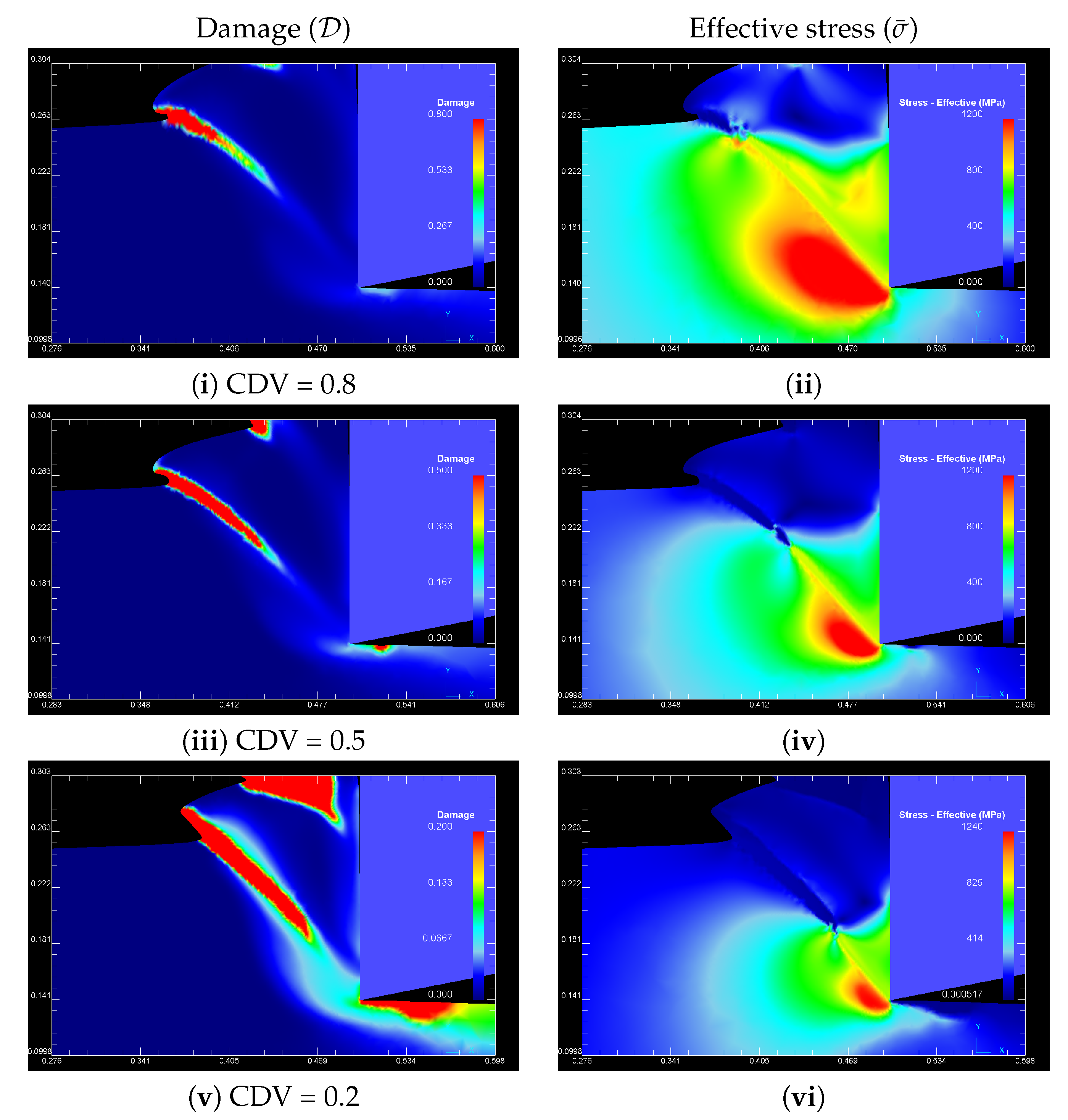
Due to the lack of experimental data, a parametric study of the CDV is undertaken to identify its influence on the degradation mechanism. In this context, three CDV are considered, i.e., 0.8, 0.5 and 0.2 with cutting conditions: v = 200 m/min, feed = 0.10 mm/rev, rake angle γ = 0 . For each case, the maximum damage contour has been set to the corresponding CDV, and additionally the effective stress is shown (Figure 7). Simulation snapshots are taken at the final stage of failure during one cycle of ASB formation. In all examined cases, we observe damage initiation near the free surface and progressive degradation inside the ASB towards the tool tip. The effective stress contours show the stress collapse for those elements that reached the CDV. Furthermore, with a decrease in CDV, the length of the degradation zone inside the ASB is extended and henceforth the chip segmentation becomes more severe.

5. Further Numerical Observations

5.1. Nucleation, Growth and Coalescence of Discontinuous Degraded Element Sets within an ASB

In this section we investigate detailed features of the damage evolution process during ASB initiation and growth. First, the NCL damage model is used with CDV = 0.2 and the following cutting conditions are considered: Speed v = 40 m/s, feed = 0.08 mm/rev, rake angle γ = 0 . Figure 8a–d shows simulation snapshots of the time sequence of the degradation mechanism. Iso-surfaces of the integral D at selected ASB evolution states are presented, whereas the maximum value is set to 0.2. From the numerical viewpoint, the element degradation mechanism proceeds in four main stages:
  • Initiation of localized degradation at elements withing the ASB and in the neighboring area around the primary shear zone (Figure 8a).
  • Damage localization in elements inside the ASB (Figure 8b);
  • Severe damage localization of elements within the ASB–Discontinuous element degradation pattern inside the ASB (Figure 8c);
  • Coalescence of degraded elements forming a macrocrack within the ASB, i.e., D = CDV (Figure 8d).
An interesting finding which is indicated from simulation is the fact that two separate damage initiation regions are existing simultaneously along the ASB, one near the free surface and the other located near the tool tip, which eventually merge forming a macro crack inside the ASB. This evidence suggests that cracks can be also initiated internally along the ASB, a result which is also confirmed by experimental investigations of orthogonal cutting of Ti6Al4V [4,61].
The discontinuous degradation mechanism can also be observed in different cutting conditions, i.e., speed v = 60 m/s, feed = 0.01 mm/rev, rake angle γ = 0 . Since damage localization is sensitive to the mesh size, simulations with a mesh size of h 0.2 μ m and h 0.1 μ m have been conducted to highlight the mesh dependency as shown in Figure 9 and Figure 10, respectively. One can observe the decrease of the damage bandwidth (normal direction of ASB propagation) as the element size decreases. Simulation snapshots show the integral D using iso-surfaces in which the maximum value is set to 0.2. In both spatial discretizations, simulations reveal a pattern of discontinuous iso-surface damage contours forming an array of nearly ellipsoidal shapes nucleating within the ASB. These discontinuous iso-surface damage arrays grow until their edges reach the boundary of the band, where the strength of the material is higher due to the lower temperature. Damage growth continues, and the iso-surface damage arrays are eventually coalesce, creating a complete separation within the ASB.
A plausible explanation of the numerically predicted discontinuous damage degradation mechanism could be attributed to a state where the CDV is reached almost simultaneously for all finite elements inside the ASB. Therefore, the probability of failure is equal along the ASB. Due to the small time-scale of the mechanism, when the stress inside a finite element collapses due to damage failure, the sudden stress drop enhance stress concentration in the neighboring elements, thus activating further damage kinetics in these elements. This mechanism results in a pattern which resembles a random array of discontinuous degraded elements. From the simulation results it can be concluded that ductile damage within the ASB is a post-failure mechanism inherent with ASB formation.
The patterns predicted numerically are in close agreement with experimental results of Ti6Al4V through the radial collapse of a thick-walled cylinder produced by a convergent shock wave presented in Figure 11 [62]. In this process the material sustains high-strain-rate deformation of the order of ϵ ¯ ˙ 10 4 s 1 . A similar observation has been made by Woei Shyan and Chi-Feng [63,64] where a typical array of coalesced voids in a well-developed shear band for a Ti6Al4V cylindrical specimen impacted by means of a split-Hopkinson pressure bar under 2.0 × 10 3 s 1 at 700 C was found. The authors emphasized that initially the voids are spherical, but when their diameters reach the thickness of the shear bands, the voids coalesce and their extension along the shear band results in elongated cavities and smooth-sided cracks. From the fracture features mentioned above, it is evident that Ti6Al4V is very susceptible to failure by adiabatic shearing, and that the voids or trains of voids can cause microcracks to form in the bands.

5.2. Temperature Field inside a Well Formed ASB

Here, the temperature field inside a well formed ASB is investigated. Detailed simulations using a high mesh density at different cutting conditions in both examined models indicate that the temperature distribution within a well formed ASB is laminar (see for example Figure 3 and Figure 6). This result is consistent with the prevailing theoretical models which state that the plastic flow within the ASB is essentially laminar [65,66,67]. However, experimental observations of impact of pre-fatigued single edge notched specimens using a linear array of high speed IR detectors contradict the laminar flow assumption. These experiments revealed a highly transient two-dimensional temperature field within a well developed ASB [68,69]. The authors assume that this structure is highly non-uniform and possesses a transient, short range of periodicity in the direction of shear band growth like an array of intense ‘hot spots’, reminiscent of the well-known shear-induced hydrodynamic instabilities in fluids (see Figure 12).
It is interesting to provide a numerical counterpart of the experimental observations shown in Figure 12 for the temperature distribution inside a well developed ASB in orthogonal machining. To this end, Figure 13 shows iso-contours of Δ T = 9 C with T min = 700 C and T max = 770 C. Small zones of intense temperature develop along the ASB with an average distance of Δ S = 1 μ m. However, one can observe that the hot spots are located exactly at the spatial discretization of the field, i.e., at the nodes of neighboring finite elements. Therefore, we may expect that the predicted small-scale spatial temperature inhomogeneities are attributed to a mechanism related to the mesh and that turbulent states are not likely to be revealed. Even though the configuration and length scale of the aforementioned experiment is different from the present case, there is a crucial need for a deeper investigation of this issue in future studies.

5.3. Temperature Reflection

Another phenomenon during the ASB formation is the temperature rise due to plastic strain localization at the free surface which gives rise to the initiation of a secondary ASB. This shear band propagates inside the primary shear zone at the opposite direction towards the tool tip. Figure 14 shows the temperature rise and the effective strain localization at the free surface. Simulation snapshots are taken at: (i), (ii) t = 8.80 μ s and (iii), (iv) t = 10.14 μ s (speed v = 200 m/min, feed = 150 mm/rev, rake angle γ = 0 , CDV = 0.2). It should be remarked that this phenomenon has been also observed in the 3D simulations of Shaofan et al. [70] using mesh-free Galerkin simulations of dynamic shear band propagation. According to the authors, a plausible explanation for this temperature reflection is the fact that the plastic shear wave reaches the lateral free surface before the shear band. The free-surface traction boundary condition amplifies the amplitude of the plastic wave, and causes the local temperature rise and the subsequent thermal softening at the free surface.
Furthermore, it can also be observed that during the formation of the first chip segment, a third shear zone initiates at the upper part of the tool/workpiece interface and propagates almost perpendicular to the primary shear zone. This shear band eventually slows down and finally arrested, thus no further strain localization occurs within this band.

5.4. Fields of State Variables during ASB Formation

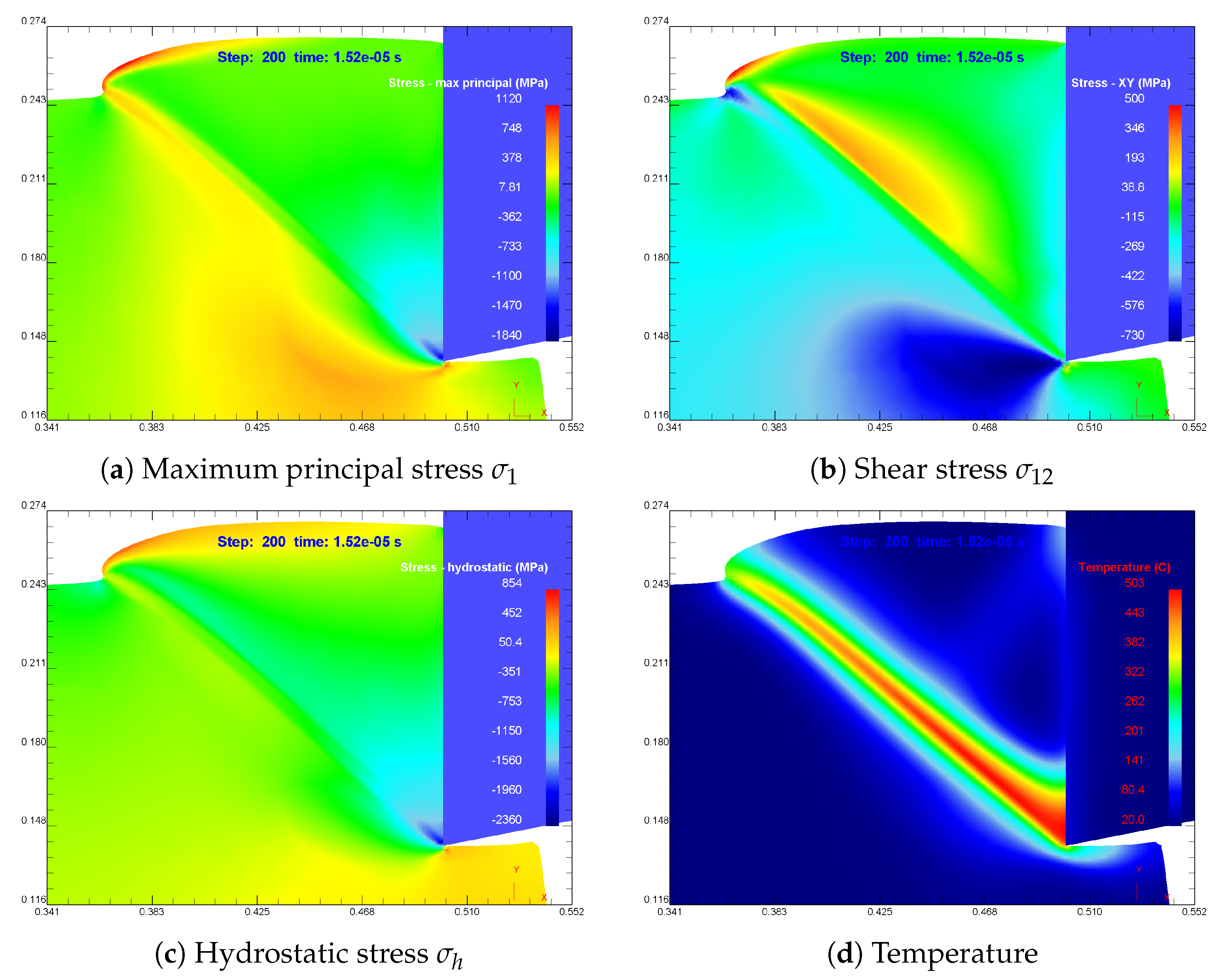
In this section an investigation of selected state variables during ASB formation is performed considering solely the thermoplastic shear mechanism. Since the stress state has a significant effect on the ductile damage degradation mechanism, the influence on damage initiation and propagation is studied regarding the maximum principal stress, the shear stress and the hydrostatic stress.
Figure 15a illustrates the maximum principal stress σ 1 distribution during ASB formation at speed of v = 200 m/min and feed = 0.1 mm/rev at a simulation snapshot at t = 1.52 × 10 5 s. It is observed that the maximum principal stress in the primary shear zone is greater near the free surface than close to the tool tip. Moreover, the maximum principal stress is positive in the former region and negative at the latter which enhances the appearance of failure near the free surface.
Moreover, from Figure 15b it is indicated that at the area under the primary shear zone the shear stress σ 12 is negative but has the maximum absolute value, while at the area above the primary shear zone the shear stress is positive. Along the primary shear zone, the shear stress has a maximum absolute value in the region near the free surface which suggests that the occurrence of failure is more possible in this region.
Hydrostatic pressure (mean stress) σ h = ( σ 1 + σ 2 + σ 3 ) / 3 has a strong influence on the fracture mode and the fracture strain, although it does not change the plastic flow. Examining the distribution of σ h along the primary shear zone, high negative values occur near the cutting tip area which allows the plastic deformation to increase without triggering mechanisms of nucleation and coalescence of microvoids. In contrast, lower negative values of σ h occur near the free surface, thus favoring the growth of cracks in this region (see Figure 15c). Note that positive values of hydrostatic stress help the growth of microvoid dimensions.
Finally, the temperature distribution at the same simulation snapshot is presented in Figure 15d. A well developed ASB can be observed with maximum temperature T 0 500 C close to the cutting edge which causes thermal softening and thereby enforcing catastrophic thermoplastic slip.
From the above distributions of stress and temperature variables it can be further explained the possible occurrence of ductile damage along the shear zone, initiating from the free surface towards the tool tip, as has been shown in Section 4.2 (see Figure 7). However, as discussed in Section 5.1, depending on the cutting conditions, damage can nucleate simultaneously everywhere inside the ASB so that no clear statements can be given about the location where damage initiates.

5.5. Chip Formation in Various Cutting Speeds

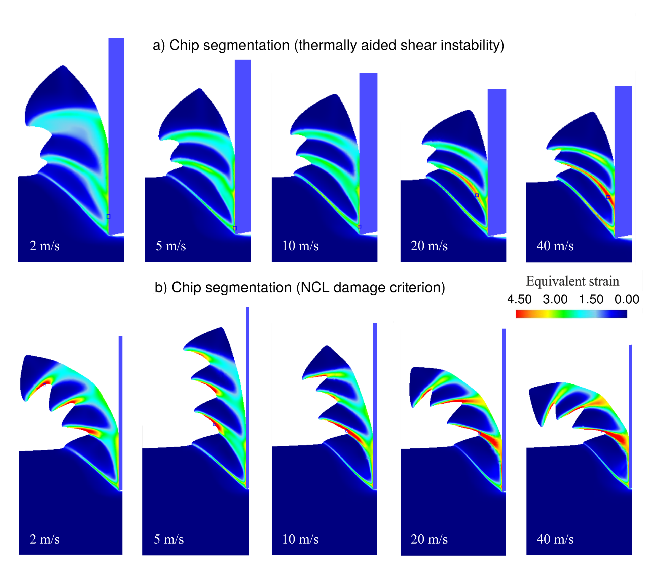
Here, the thermally aided shear instability and the ductile damage mechanisms are studied over a wide range of cutting speeds, e.g., v = 1 , 2 , 5 , 10 , 20 and 40 m/s. Figure 16a illustrates the chip morphology obtained under different deformation rates using the effective strain contours. The maximum scale of the effective strain is set equal to ϵ ¯ = 4.5 . Numerical simulations show that the increase of cutting speed enforces the strain localization within the ASB, and consequently the strain gradients perpendicular to the band. Similar observations are obtained when the NCL damage criterion (CDV = 0.5) is implemented in the numerical model (see Figure 16b).
The evolution of the main cutting force F x (see Figure 17) vs. speed considering the thermally aided shear instability (feed = 0.08 mm/rev, rake angle γ = 0 ) is illustrated in Figure 18. In all curves, the main cutting force shows periodic oscillations with a well defined time period Δ t . A mean cutting force F ¯ x is defined as the mean of the sum of the instantaneous values of F x taken during one complete cycle Δ t and is given as F ¯ x = 1 Δ t 0 Δ t F x ( t ) d t . A drop of F ¯ x and a decrease of the time period Δ t can be observed with an increase in speed. The time instant where F x ( t ) = F ¯ x corresponds to the initiation of a new chip segment. Each drop of the force beyond the maximum point coincides with material collapse due to the formation of an ASB triggered by thermoplastic shear.
Another aspect of the shear localization is the chip segmentation frequency defined as the number of segments produced per time unit. Since the ASB formation causes a periodic oscillation of the cutting forces, the period of oscillation Δ t is associated to successive ASB formation where the segmentation frequency is f = 1 / Δ t . Figure 19 shows the chip segmentation frequency against speed in a log-log diagram for two cases: (a) Thermally aided shear instability, and (b) NCL damage criterion (CDV = 0.2, 0.5). In both cases, chip segmentation frequency increases with an increase in speed. It can be observed that the chip segmentation frequency is higher in the former case over the whole range of the examined speeds. The slope in the investigated speed regime is approximately ≈1 and indicates that f v for both models. Moreover, the segmentation frequency slope is not affected by the change of CDV. These numerical results are in reasonable agreement with experiments in orthogonal machining of Ti6Al4V where the experimental points in a log-log diagram are remarkably aligned on a straight line with slope ≈ 1 for cutting speeds v > 1.5 m/s [18,61]. Further information on the ASB spacing in high-speed machining under different cutting speeds and feed rates can be found in [71].

6. Orthogonal Cutting Experiments of Ti6Al4V

An experimental approach to investigate the effect of cutting speed and feed rate on the chip morphology as well as on the cutting forces in orthogonal machining of Ti6Al4V is undertaken. This work was conducted on a CNC lathe machine (DMG Alpha 500) using a specific setup as illustrated in Figure 17. A tube with outer diameter of 40 mm and wall thickness of 2.5 mm was used in order to obtain orthogonal cutting conditions. Hence, considering a maximum feed rate of 0.2 mm/rev, a nearly plane strain deformation can be realized. The cutting tool was a Kennametal carbide coated insert (TPGN160308/KC5010) mounted on a tool holder (CTGPL2020K16). The advanced PVD AlTiN coating over the deformation-resistant unalloyed carbide substrate of the cutting insert is appropriate for machining Titanium alloys under stable conditions at higher speeds. The workpiece material was Ti6Al4V Grade 5 annealed, where its chemical composition and its physical properties are presented in Table 1 and Table 2, respectively. The cutting forces were measured by means of a dynamometer (Kistler 9257B) and appropriate data acquisition equipment (NI PCI-MIO-16E—1 MHz).
All experiments performed in a range of cutting conditions corresponding to feed rates of 0.05, 0.1, 0.15 and 0.2 mm/rev and cutting speeds of 50, 100, 150 and 200 m/min. The limited cutting conditions used in this study was due to excessive heating and damage of the cutting edge. However, even those small range of experiments provided useful results for FEM validation. After cutting, the chips have been embedded into resin and their lateral section was mechanically polished and etched. Then, an optical microscope is used to examine the chip morphology and ASB formation.
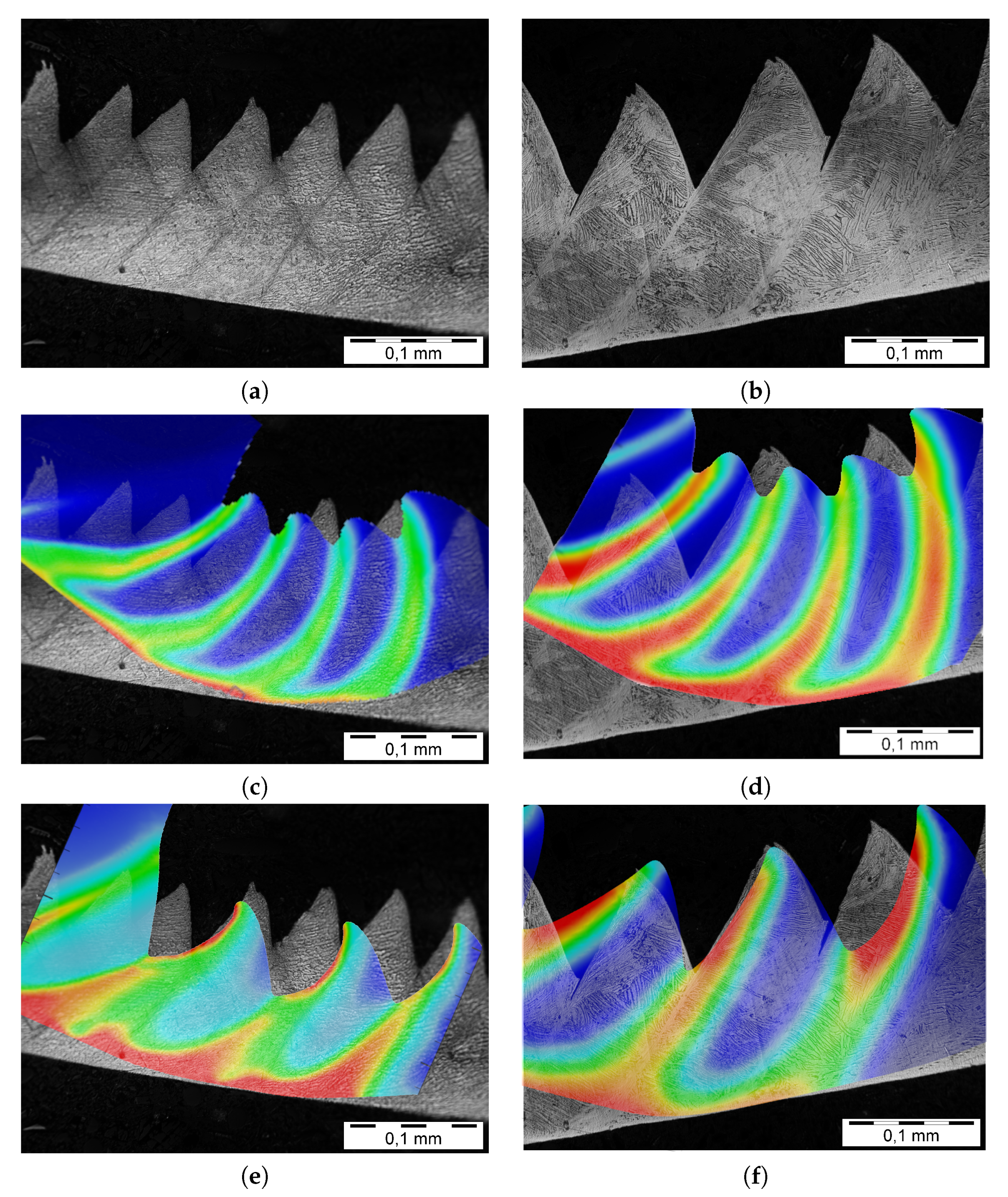
The chip morphology and segmentation show different characteristics at various speeds and feed rates. As an example, Figure 20a,b illustrate the chip microstructure which displays well-developed shear bands developed at a cutting speed of 200 m/min for feed rates 0.10 and 0.15 mm/rev (rake angle γ = 0 ), respectively. Clearly, one can observe that the increase in feed rate reduces the segmentation frequency.
A superposition of images is used for a direct comparison with FEM simulations. This approach allows a holistic view of the plastic deformation, which is also informative for the ASB evolution at each cutting condition. Figure 20c,d show the FEM chip morphologies superimposed on the experimental optical micrographs after appropriate scaling and adjustment, obtained at a speed of 200 m/min for feed rates 0.10 and 0.15 mm/rev, respectively. Both figures present solutions of the thermally aided shear instability. It is evident that FEM simulations predict a smaller chip compression ratio λ = h c / h c u .
Moreover, at the optical micrographs the ASB seems to follow a straight line in contrast to the arc shape predicted from the simulation. Even though the high bending of the FEM chip does not permit a precise positioning on the reference micrographs, one may consider to unfold the FEM chip and observe a smaller chip thickness h c and an increase of the chip segmentation distance δ (distance between two successive ASBs at the tool rake face).
Nevertheless, a more profound discrepancy concerns the chip geometry at the free boundary. Due to the large bending of the chip, the spacing between the chip peaks at the upper part of the FEM chip (free surface) tends to decrease compared with the actual real geometry. Thus, it can be concluded that thermally aided shear instability cannot accurately predict the sharp shaw-tooth shape in the low speed regime. This fact suggests that most probably the chip form at the free surface occurs due to a damage mechanism since it cannot attributed to any other physical mechanism within the process.
Additionally, Figure 20e,f shows the FEM chip morphology corresponding to NCL damage criterion (CDV = 0.8) superimposed on the experimental optical micrographs for the same loading conditions. The predicted ASB follows a straight line which can be deemed as consistent with the experimental findings. Observe the noticeable difference of the chip segmentation spacing δ with the ones corresponding to the FEM based analysis being higher. This behavior is similar to the one observed in Figure 19 where the segmentation frequency decreases in the whole range of cutting speeds when ductile damage is introduced in the model. However, in this case, the FEM geometry of the free boundary more accurately resembles the actual shaw-tooth chip form. It is important to emphasize that the sharp saw-tooth shape was predicted in all cutting conditions using the NCL damage criterion; an outcome in agreement with experimental evidence (compare results in Figure 6, Figure 20, and additionally for higher cutting speeds in Figure 16).
Another part of the experimental work concerns the acquisition and analysis of the cutting forces. It is well-known that chip formation is directly related to the emerging cutting forces. Primarily, the effect of feed rate has an impact on the uncut chip thickness h c u and thereby on the main cutting force F x . The measured main cutting force (mean values) F ¯ x against speed and the relationship with feed rate is shown with the corresponding simulation results in Figure 21. The curves show a small decrease on the magnitude of F ¯ x with an increase in speed. The constitutive law defined in [38] describes in an accurate manner the flow stress level for the conducted range of speeds since the correlation between FEM predictions and experimental measurements can be deemed as satisfactory.

7. Synopsis and Perspectives

In this paper a computational study of the ASB formation during orthogonal machining of Ti6Al4V has been performed using an implicit, non-isothermal, RVP finite element formulation. The following two main modeling approaches have been investigated in a wide range of conditions: (i) Thermally aided shear instability mechanism, and (ii) thermally aided shear instability coupled with a ductile damage mechanism. A wide set of simulations provided visual demonstrations of ASB propagation and related physical mechanisms. Experimental results of ASB formation in orthogonal machining evaluate the FEM model at the low speed regime. The most significant conclusions can be outlined in the following:
  • The synergistic effect of the thermally aided shear instability and ductile damage on ASB formation and evolution is numerically investigated. Simulations show that ductile damage within the ASB is a post-localization failure mechanism occurring after intense shear localization.
  • Simulations under different cutting conditions successfully predict cases in which damage initiated near the free surface but also ones that occur randomly everywhere within the ASB as well as near the tool tip. This result is bridging contradicting theories regarding the damage initiation regions.
  • Detailed simulations using the NCL ductile damage model revealed an array of discontinuous degraded elements of nearly ellipsoidal shapes, which grows and progressively coalescence forming a macro crack inside the ASB.
  • Numerical simulations predict that the chip segmentation frequency over the range of the numerically examined speeds, v = [ 2 , 40 ] m/s (feed = 0.08 mm/rev), presents a slope of approximately equal to 1 (in a log-log diagram) which indicates that the segmentation frequency is proportional to speed ( f n u m v ) for both models.
  • In the limited range of examined cutting conditions, the estimated FEM mean forces are in good correlation with the ones measured in the experiments.
  • Experimental results based on chip morphology confirm that thermally aided shear instability cannot predict accurately the saw-tooth geometry at the low speed regime. This fact suggests that a damage mechanism during the last stages of ASB evolution is susceptible for the chip form at the free boundary.
  • Superposition of the FEM chips on experimental optical micrographs show discrepancies regarding the predicted plastic deformation for both models.
  • The initiation and propagation of the ASB cannot be deemed as sensitive to mesh alignment. On the other hand, and as expected, the ASB formation with the introduction of the ductile damage criterion can be considered as extremely sensitive to the mesh size.
  • Finally, the spatial discretization used in FEM simulations cannot confirm the existence of a turbulent temperature field within a well developed ASB. Determination of the temperature field state in ASBs (laminar or turbulent) is still an open problem which has to be further studied numerically.

Author Contributions

Data curation, O.F. and D.S.; Formal analysis, O.F., C.N.D. and D.S.; Investigation, O.F., C.N.D. and A.K.; Methodology, O.F., C.N.D. and A.K.; Resources, A.K.; Software, O.F. and D.S.; Supervision, C.N.D.; Validation, O.F. and C.N.D.; Visualization, O.F. and D.S.; Writing - original draft, O.F., C.N.D. and D.S. All authors have read and agreed to the published version of the manuscript.

Funding

This research received no external funding.

Acknowledgments

This research has been supported by the Manufacturing Technology & Machine Tools Laboratory (MT-LAB) of the International Hellenic University, Serres Campus.

Conflicts of Interest

The authors declare no conflicts of interest.

References

  1. Zener, C.; Hollomon, J.H. Effect of strain rate upon plastic flow of steel. J. Appl. Phys. 1944, 15, 22–32. [Google Scholar] [CrossRef]
  2. Recht, R.F. Catastrophic Thermoplastic Shear. Trans. ASME 1964, 31, 189–193. [Google Scholar] [CrossRef]
  3. Shaw, M.C.; Vyas, A. Chip Formation in the Machining of Hardened Steel. Ann. CIRP 1993, 42/1, 29–33. [Google Scholar] [CrossRef]
  4. Komanduri, R.; Turkovich, B.F. New observations on the mechanism of chip formation when machining titanium alloys. Wear 1981, 69, 179–188. [Google Scholar] [CrossRef]
  5. Nakayama, K. The formation of saw tooth chips. In Proceedings of the International Conference on Production Engineering, Tokyo, Japan, 26–29 August 1974; pp. 572–577. [Google Scholar]
  6. Nakayama, K.; Arai, M.; Kanda, T. Machining characteristics of hard materials. Ann. CIRP 1988, 37, 89–92. [Google Scholar] [CrossRef]
  7. Vyas, A.; Shaw, M.C. Mechanics of shaw-tooth chip formation in metal cutting. J. Manuf. Sci. Eng. 1999, 121, 163–172. [Google Scholar] [CrossRef]
  8. Bai, Y.; Dodd, B. Adiabatic Shear Localization; Pergamon: Oxford, UK, 1992. [Google Scholar]
  9. Wright, T.W. The Physics and Mathematics of Adiabatic Shear Bands; Cambridge Monographs on Mechanics; Cambridge University Press: Cambridge, UK, 2002. [Google Scholar]
  10. Komanduri, R. Some clarifications on the mechanics of chip formation when machining titanium alloys. Wear 1982, 76, 15–34. [Google Scholar] [CrossRef]
  11. Rogers, H.C. Adiabatic plastic deformation. Annu. Rev. Mater. Sci. 1979, 9, 283–311. [Google Scholar] [CrossRef]
  12. Rogers, H.C.; Shastry, C.V. Material Factors in Adiabatic Shearing in Steels. In Shock Waves and High-Strain-Rate Phenomena in Metals; Meyers, M.A., Murr, L.E., Eds.; Springer: Boston, MA, USA, 1981. [Google Scholar]
  13. Timothy, S.P.; Hutchings, M. The structure of adiabatic shear bands in a titanium allloy. Acta Met. 1985, 33, 667–676. [Google Scholar] [CrossRef]
  14. Landau, P.; Osovski, S.; Venkert, A.; Gartnerova, V.; Rittel, D. The genesis of adiabatic shear bands. Sci. Rep. 2016, 6, 37226. [Google Scholar] [CrossRef] [Green Version]
  15. Sutter, G.; List, G. Very high speed cutting of Ti–6Al–4V titanium alloy-change in morphology and mechanism of chip formation. Int. J. Mach. Tools Manuf. 2013, 66, 37–43. [Google Scholar] [CrossRef]
  16. Navarro, P.F.; Chiu, P.H.; Higgins, A.; Serge, M.; Benson, D.J.; Nesterenko, V.F. Shear band patterning and post-critical behavior in AISI 4340 steel with different microstructure. Int. J. Impact Eng. 2018, 112, 144–154. [Google Scholar] [CrossRef] [Green Version]
  17. Komanduri, R.; Hou, Z.B. On Thermoplastic Shear Instability in the Machining of a Titanium Alloy (Ti-6Al-4V). Metall. Mater. Trans. A 2002, 33A, 2995–3010. [Google Scholar] [CrossRef]
  18. Molinari, A.; Soldani, X.; Miguélez, M.H. Adiabatic shear banding and scaling laws in chip formation with application to cutting of Ti-6Al-4V. J. Mech. Phys. Solids 2013, 61, 2331–2359. [Google Scholar] [CrossRef]
  19. Shivpuri, R.; Hua, J.; Srivastava, P.M.A.K.; Lahoti, G.D. Microstructure-Mechanics Interactions in Modeling Chip Segmentation during Titanium Machining. CIRP Ann. 2002, 51, 71–74. [Google Scholar] [CrossRef]
  20. Baker, M. The influence of plastic properties on chip formation. Comput. Mater. Sci. 2003, 28, 556–562. [Google Scholar] [CrossRef]
  21. Calamaz, M.; Coupard, D.; Girot, F. A new material model for 2D numerical simulation of serrated chip formation when machining titanium alloy Ti–6Al–4V. Int. J. Mach. Tools Manuf. 2008, 48, 275–288. [Google Scholar] [CrossRef] [Green Version]
  22. Belytschko, T.; Krongauz, Y.; Organ, D.; Fleming, M.; Krysl, P. Meshless methods: An overview and recent developments. Comput. Methods Appl. Mech. Eng. 1996, 139, 3–47. [Google Scholar] [CrossRef] [Green Version]
  23. Duarte, C.A.; Oden, J.T. An hp adaptive method using clouds. Comput. Methods Appl. Mech. Eng. 1996, 139, 237–262. [Google Scholar] [CrossRef]
  24. Babuska, I.; Melenk, J.M. The partition of unity method. Int. J. Numer. Methods Eng. 1997, 40, 727–758. [Google Scholar] [CrossRef]
  25. Gingold, R.A.; Monaghan, J.J. Smoothed Particle Hydrodynamics: Theory and Application to Non-Spherical Stars. Mon. Not. R. Astron. Soc. 1977, 181, 375–389. [Google Scholar] [CrossRef]
  26. Liu, W.K.; Chen, Y.; Jun, S.; Chen, J.S.; Belytschko, T.; Pan, C.; Uras, R.A.; Chang, C.T. Overview and Applications of the Reproducing Kernel Particle Methods. Arch. Comput. Methods Eng. State Art Rev. 1996, 3, 3–80. [Google Scholar] [CrossRef]
  27. Chen, J.-S. Cristina Maria Oliveira Lima Roque, Chunhui Pan, Sérgio Tonini Button, Analysis of metal forming process based on meshless method. J. Mater. Process. Technol. 1998, 80–81, 642–646. [Google Scholar] [CrossRef]
  28. DEFORM-2D. Scientific Forming Technologies Corporation, Version 10.2 User’s Manual; Scientific Forming Technologies Corporation: Columbus, OH, USA, 2011. [Google Scholar]
  29. Hill, R. The Mathematical Theory of Plasticity; Oxford University Press: London, UK, 1971. [Google Scholar]
  30. Zienkiewicz, O.C.; Godbole, P.O. Flow of plastic and visco-plastic solids with special reference to extrusion and forming processes. Int. J. Numer. Methods Eng. 1974, 8, 3–16. [Google Scholar] [CrossRef]
  31. Kobayashi, S.; Oh, S.I.; Altan, T. Metal Forming and the Finite-Element Method; Oxford University Press: London, UK, 1989. [Google Scholar]
  32. Rebelo, N.; Kobayashi, S. A Coupled Analysis of Viscoplastic Deformation and Heat Transfer—I. Int. J. Mech. Sci. 1980, 22, 699. [Google Scholar] [CrossRef]
  33. Rebelo, N.; Kobayashi, S. A Coupled Analysis of Viscoplastic Deformation and Heat Transfer—II. Int. J. Mech. Sci. 1980, 22, 707. [Google Scholar] [CrossRef]
  34. Marusich, T.D.; Ortiz, M. Modeling and Simulation of High-Speed Machining. Int. J. Numer. Methods Eng. 1995, 38/21, 3675–3694. [Google Scholar] [CrossRef] [Green Version]
  35. Ortiz, M.; Leroy, Y.; Needleman, A. A finite element method for localized failure analysis. Comput. Methods Appl. Mech. Eng. 1987, 61, 189–214. [Google Scholar] [CrossRef]
  36. Fish, J.; Belytschko, T. Elements with embedded localization zones for large deformation problems. Comput. Struct. 1988, 30, 247. [Google Scholar] [CrossRef]
  37. El-Magd, E.; Treppmann, C. Simulation of Chip Root Formation at High Cutting Rates by Means of Split-Hopkinson Bar Test. Mater. Ger. Journal: Mater. Test. 1999, 41/11, 457–460. [Google Scholar]
  38. Treppmann, C. Flieverhalten metallischer Werkstoffe bei Hochgeschwindigkeitsbeanspruchung. Ph.D. Thesis, RWTH, Aachen, Germany, 2001. [Google Scholar]
  39. Taylor, G.I.; Quinney, H. The latent energy remaining in a metal after cold working. Proc. R. Soc. Lond. A 1934, 143, 307–326. [Google Scholar]
  40. Mason, J.J.; Rosakis, A.J.; Ravichandran, G. On the strain and strain rate dependence of the fraction of plastic work converted to heat: An experimental study using high speed infrared detectors and the Kolsky bar. Mech. Mater. 1994, 17, 135–145. [Google Scholar] [CrossRef]
  41. Kapoor, R.; Nemat-Nasser, S. Determination of temperature rise during high strain rate deformation. Mech. Mater. 1998, 27, 1–12. [Google Scholar] [CrossRef]
  42. Nemat-Nasser, S.; Guo, W.G.; Nesterenko, V.F.; Indrakanti, S.S.; Gu, Y.B. Dynamic response of conventional and hot isostatically pressed Ti6Al4V alloys: Experiments and modeling. Mech. Mater. 2001, 33, 425–439. [Google Scholar] [CrossRef]
  43. Duncan, A.S.; Macdougall, P.; Maudlin, J. The proportion of plastic work converted to heat in Ti-6Al-4V: MTS model prediction and experimental data. In Proceedings of the Explomet 2000, Albuquerque, NM, USA, 19–23 June 2000. [Google Scholar]
  44. Rosakis, P.; Rosakis, A.J.; Ravichandran, G.; Hodowany, J. A thermodynamic internal variable model for the partition of plastic work into heat and stored energy in metals. J. Mech. Phys. Solids 2000, 48, 581–607. [Google Scholar] [CrossRef]
  45. Childs, T.H.; Dirikolu, M.H.; Sammons, M.D.S.; Maekawa, K.; Kitagawa, T. Experiments on and Finite Element Modeling of Turning Free-Cutting Steels at Cutting Speeds up to 250 m/min. In Proceedings of the 1st French and German Conference on High-speed Machining, Metz, France, June 1997; pp. 325–331. [Google Scholar]
  46. Wright, P.K.; Horne, J.G.; Tabor, D. Boundary Conditions at the Chip-Tool Interface in Machining: Comparisons Between Seizure and Sliding Friction. Wear 1979, 54, 371–390. [Google Scholar] [CrossRef]
  47. Samiatin, S.L.; Rao, S.B. Shear localization during metal cutting. J. Mater. Sci. Eng. 1983, 61, 185–192. [Google Scholar] [CrossRef]
  48. Marchand, A.; Duffy, J. An experimental study of the formation process of adiabatic shear bands in a structural steel. J. Mech. Phys. Solids 1988, 36, 251–283. [Google Scholar] [CrossRef]
  49. Medyanik, S.N.; Liu, W.K.; Li, S. On criteria for dynamic adiabatic shear band propagation. J. Mech. Phys. Solids 2007, 55, 1439–1461. [Google Scholar] [CrossRef]
  50. Lee, D. The effect of cutting sped on chip formation under orthogonal machining. J. Eng. Ind. Trans. ASME 1985, 107, 55–63. [Google Scholar] [CrossRef]
  51. Grebe, H.A.; Pak, H.R.; Meyers, M.A. Adiabatic shear localization in titanium and Ti6Al4V alloy. Met. Trans. A 1985, 16A, 761–775. [Google Scholar] [CrossRef]
  52. Kailas, S.V.; Prasad, Y.V.R.K.; Biswas, S.K. Flow instabilities and fracture in Ti-6Al-4V deformed in compression at 298-673 K. Metall. Mater. Trans. A 1994, 25A, 2173–2179. [Google Scholar] [CrossRef]
  53. Schoenfeld, S.E.; Wright, T.W. A failure criterion based on material instability. Int. J. Solids Struct. 2003, 40, 3021–3037. [Google Scholar] [CrossRef]
  54. Cockcroft, M.G. Ductility; American Society for Metals: Metals Park, OH, USA, 1968; pp. 199–226. [Google Scholar]
  55. Cockcroft, M.G.; Latham, D.J. Ductility and workability of materials. J. Inst. Met. 1968, 96, 33–39. [Google Scholar]
  56. Oh, S.I.; Kobayashi, S.; Chen, C.C. Ductile fracture in axisymmetric extrusion and drawing. J. Eng. Ind. ASME 1979, 101. [Google Scholar] [CrossRef]
  57. Avitzur, B. Metal Forming Process and Analysis; Mc Graw Hill Book Company: New York, NY, USA, 1968. [Google Scholar]
  58. Affouard, J.L.; Dormeval, R.; Stelly, M.; Ansart, J.P. Adiabatic shear bands in metals and alloys under dynamic compressive conditions. In Proceedings of the Third Conference on the Mechanical Properties at High Rates of Strain, Oxford, UK, 9–12 April 1984; Harding, J., Ed.; Institute of Physics: Bristol, UK, 1984; pp. 533–540. [Google Scholar]
  59. Giovanola, J. Adiabatic shear banding under pure shear loading. 1. Direct observation of strain localization and energy measurements. Mech. Mater. 1988, 7, 59–71. [Google Scholar] [CrossRef]
  60. Giovanola, J. Adiabatic shear banding under pure shear loading. 2. Fractographic and metallographic observations. Mech. Mater. 1988, 7, 72–87. [Google Scholar] [CrossRef]
  61. Cotterell, M.; Byrne, G. Dynamics of chip formation during orthogonal cutting of titanium alloy Ti-6Al-4V. CIRP Ann. Manuf. Technol. 2008, 57, 93–96. [Google Scholar] [CrossRef]
  62. Xue, Q.; Meyers, M.A.; Nesterenko, V.F. Self-organization of shear bands in titanium and Ti-6Al-4V alloy. Acta Mater. 2002, 50, 575–596. [Google Scholar] [CrossRef]
  63. Lee, W.-S.; Lin, C.-F. Plastic deformation and fracture behaviour of Ti–6Al–4V alloy loaded with high strain rate under various temperatures. Mater. Sci. Eng. 1998, A241, 48–59. [Google Scholar] [CrossRef]
  64. Lee, W.-S.; Lin, C.-F. High-temperature deformation behaviour of Ti6Al4V alloy evaluated by high strain-rate compression tests. J. Mater. Process. Technol. 1998, 75, 127–136. [Google Scholar] [CrossRef]
  65. Wright, T.W.; Ravichandran, G. Canonical aspects of adiabatic shear bands. Int. J. Plast. 1997, 13, 309–325. [Google Scholar] [CrossRef]
  66. Molinari, A.; Leroy, Y.M. Existence And Stability Of Stationary Shear Bands With Mixed-Boundary Conditions. Comptes Rendus L’AcadéMie Des Sci. 1990, 310, 1017–1023. [Google Scholar]
  67. Gioia, G.; Ortiz, M. The two-dimensional structure of dynamic boundary layers and shear bands in thermoviscoplastic solids. J. Mech. Phys. Solids 1996, 44, 251–292. [Google Scholar] [CrossRef]
  68. Guduru, P.R.; Ravichandran, G.; Rosakis, A.J. Observations of transient temperature vortical microstructures in solids during adiabatic shear banding. Phys. Rev. E 2001, 64, 036128. [Google Scholar] [CrossRef] [Green Version]
  69. Guduru, P.R.; Rosakis, A.J.; Ravichandran, G. Dynamic shear bands: An investigation using high speed optical and infrared diagnostics. Mech. Mater. 2001, 33, 371–402. [Google Scholar] [CrossRef]
  70. Li, S.; Liu, W.K.; Rosakis, A.J.; Belytschko, T.; Hao, W. Mesh-free Galerkin simulations of dynamic shear band propagation and failure mode transition. Int. J. Solids Struct. 2002, 39, 1213–1240. [Google Scholar] [CrossRef]
  71. Yang, Q.; Liu, Z.; Shi, Z.; Wang, B. Analytical modeling of adiabatic shear band spacing for serrated chip in high-speed machining. Int. J. Adv. Manuf. Technol. 2014, 71, 1901–1908. [Google Scholar] [CrossRef]
Figure 1. Orthogonal machining parameters; cutting speed v, uncut chip thickness h c u , chip thickness h c , chip compression ratio λ = h c / h c u , shear angle ϕ , rake angle γ , clearance angle α , chip segmentation distance δ .
Metals 10 00338 g001
Figure 2. Mesh adaptivity during the simulation of adiabatic shear band (ASB) formation; minimum mesh size h m i n 0.4–1.6 μ m, maximum element size ratio = 15.
Metals 10 00338 g002
Figure 3. Temperature, equivalent strain ϵ ¯ and equivalent stress σ ¯ (von Mises) contours at different stages (af) of the ASB formation under thermally aided shear instability (v = 200 m/min, feed = 0.15 mm/rev, rake angle γ = 0 ). Simulations using a minimum mesh size of h m i n 0.4–1.6 μ m.
Metals 10 00338 g003
Figure 4. Calculation of state variables on a line approximately perpendicular to ASB. Simulation snapshot at t = 1.23 × 10 5 s.
Metals 10 00338 g004
Figure 5. Distribution of state variables on a line approximately perpendicular to ASB: shear stress σ 12 , shear strain ϵ 12 , strain rate ϵ ¯ ˙ , temperature and equivalent strain ϵ ¯ (v = 200 m/min, feed = 0.15 mm/rev, rake angle γ = 0 ).
Metals 10 00338 g005
Figure 6. Temperature, equivalent strain ϵ ¯ , equivalent stress σ ¯ (von Mises) and damage contours at different stages (af) of the chip segment formation (v = 200 m/min, feed = 0.10 mm/rev, rake angle γ = 0 ; NCL damage criterion CDV = 0.8). Simulations using a minimum mesh size of h m i n ≈ 0.4–1.6 μ m.
Metals 10 00338 g006
Figure 7. The failure mode mechanism against the critical damage value (CDV); snapshots are taken at the final stage during one cycle of ASB formation: (i) Damage and (ii) effective stress contour using CDV = 0.8; (iii) damage and (iv) effective stress contour using CDV = 0.5; (v) damage and (vi) effective stress contour using CDV = 0.2 (v = 200 m/min, feed = 0.10 mm/rev, rake angle γ = 0 ). Simulations using a minimum mesh size of h m i n 0.4–1.6 μ m.
Metals 10 00338 g007
Figure 8. Evolution of damage inside the ASB. Discontinuous element degradation and coalescence inside the ASB resulting in a macrocrack; simulation with minimum element size h 0.6 μ m; Normalized Cockcroft and Latham (NCL) criterion (CDV = 0.2); cutting conditions: v = 40 m/s, feed = 0.08 mm/rev, rake angle γ = 0 ; snapshots are taken at: (a) t = 4.43 × 10 7 s, (b) t = 5.31 × 10 7 s, (c) t = 5.69 × 10 7 s, and (d) t = 5.82 × 10 7 s.
Metals 10 00338 g008
Figure 9. Isosurfaces of of the integral D revealing the discontinuous degradation and coalescence mechanism inside ASB; minimum element size h 0.2 μ m; simulations using the NCL damage criterion (CDV = 0.2); cutting conditions: v = 60 m/s, feed = 0.01 mm/rev, rake angle γ = 0 ; snapshots are taken at: (a) t = 7.65 × 10 8 s, (b) t = 7.70 × 10 8 s, (c) t = 7.97 × 10 8 s, and (d) t = 8.31 × 10 8 s.
Metals 10 00338 g009
Figure 10. Iso-surfaces of the integral D revealing the discontinuous degradation and coalescence mechanism inside ASB; minimum element size h 0.1 μ m; simulations using the NCL damage criterion (CDV = 0.2); cutting conditions: v = 60 m/s, feed = 0.01 mm/rev, rake angle γ = 0 ; snapshots are taken at: (a) t = 7.70 × 10 8 s, (b) t = 7.94 × 10 8 s, (c) t = 8.07 × 10 8 s, and (d) t = 8.14 × 10 8 s.
Metals 10 00338 g010
Figure 11. Void nucleation and growth inside a shear band in experimental results of Ti6Al4V through the radial collapse of a thick-walled cylinder under high-strain-rate deformation (≈ 10 4 s 1 ): (a) Nucleation of voids within a shear band; (b) growth of voids; (c) elongation and rotation of voids; and (d) coalescence (with permission of [62]).
Metals 10 00338 g011
Figure 12. Highly transient two-dimensional temperature field within a well developed ASB (with permission of [68,69]).
Metals 10 00338 g012
Figure 13. The micro-structure spatial temperature profile of adiabatic shear band: (a) Level one (1); (b) level two (1); (c) level one (2); (d) level two (2).
Metals 10 00338 g013
Figure 14. The phenomenon of temperature rise and effective strain localization at the free surface before the ASB reaches the free boundary; snapshots are taken at: (i,ii) t = 8.80 μ s, and (iii,iv) t = 10.14 μ s (cutting speed v = 200 m/min, feed =150 mm/rev, rake angle γ = 0 , CDV = 0.2).
Metals 10 00338 g014
Figure 15. Distribution of the maximum principal stress σ 1 , shear stress σ 12 , hydrostatic stress σ h and temperature during the formation of an adiabatic shear band in thermally aided shear instability. Cutting conditions: v = 200 m/min, feed = 0.1 mm/rev, rake angle γ = 0 ; time step t = 1.52 × 10 5 s.
Metals 10 00338 g015
Figure 16. Equivalent strain ϵ ¯ contours during periodic chip segment formation under different speeds considering: (a) Thermally aided shear instability, (b) NCL damage criterion Critical Damage Value (CDV) = 0.5; (v = 2, 5, 10, 20 and 40 m/s, feed = 0.08 mm/rev, rake angle γ = 0 ).
Metals 10 00338 g016
Figure 17. Experimental setup in orthogonal cutting.
Metals 10 00338 g017
Figure 18. Evolution of the main cutting force F x vs. speed v under thermally aided shear instability (feed = 0.08 mm/rev, rake angle γ = 0 ).
Metals 10 00338 g018
Figure 19. Chip segmentation frequency f vs. speed v (log-log); cutting conditions (feed = 0.08 mm/rev, rake angle γ = 0 ). The slope in the investigated cutting speed regime is approximately ≈1 and indicates that f v for both models. The segmentation frequency slope remains unaffected by the change of CDV.
Metals 10 00338 g019
Figure 20. Optical micrographs of chip showing the adiabatic deformed shear bands of Ti6Al4V, obtained at v = 200 m/min, feed = 0.10 and 0.15 mm/rev (rake angle γ = 0 ). Superposition of FEM results after appropriate scaling. (a) v = 200 m/min, feed = 0.10 mm/rev; (b) v = 200 m/min, feed = 0.15 mm/rev; (c) Thermally aided shear instability; v = 200 m/min, feed = 0.10 mm/rev; (d) thermally aided shear instability; v = 200 m/min, feed = 0.15 mm/rev; (e) NCL (CDV = 0.8); v = 200 m/min, feed = 0.10 mm/rev; (f) NCL (CDV = 0.8); v = 200 m/min, feed = 0.15 mm/rev.
Metals 10 00338 g020
Figure 21. Mean cutting force F ¯ x vs. speed v. FEM and experimental results are shown for feed 0.10 and 0.15 mm/rev.
Metals 10 00338 g021
Table 1. Chemical composition of Ti6Al4V (wt%).
ContentCFeNAlVOTi
Composition0.00230.1600.0076.1904.0800.180Balance
Table 2. Physical properties of Ti6Al4V.
Hardness (HRC)Density (g/cm 3 )Re (MPa)Rm (MPa)k (W/mk)
364.4391010006.7