Article

Precipitate Behavior, Mechanical Properties and Corrosion Behavior of an Al-Zn-Mg-Cu Alloy during Non-Isothermal Creep Aging with Axial Tension Stress

1
Light Alloy Research Institute, Central South University, Changsha 410083, China
2
School of Materials Science and Engineering, Changzhou University, Changzhou 213000, China
3
School of Materials Science and Engineering, Central South University, Changsha 410083, China
*
Authors to whom correspondence should be addressed.
Metals 2020, 10(3), 378; https://doi.org/10.3390/met10030378
Submission received: 15 February 2020 / Revised: 7 March 2020 / Accepted: 9 March 2020 / Published: 16 March 2020

Abstract

:
Theprecipitate behavior, mechanical properties and corrosion behavior of an Al-Zn-Mg-Cu alloy during non-isothermal creep aging were investigated. The results show that diffraction patterns of GPI zones gradually disappear and those of η′ phases are strengthened during the heating stage. More importantly, the size and volume fraction of precipitates increase with aging temperature increasing, which greatly enhances the mechanical properties of the alloy. The hardness and tensile strength of the alloy with H210 aging condition are 165 HV and 564 MPa, respectively. During the cooling stage, in addition to the diffraction pattern of η′ phase, that of GPI zones can be observed again. Furthermore, the size of the precipitates decreases, and the volume fraction reaches a maximum. The hardness and tensile strength of the alloy with C120 aging condition reach 185 HV and 580 MPa, respectively. Furthermore, the characteristics of the grain boundary reveal that the width of precipitation free zones (PFZ) first increases during the heating stage and then decreases during the cooling stage. In the C120 condition, the newly generated secondary precipitates and the coarsening of undissolved precipitates around the grain boundary lead to the further narrowing of PFZ, but the coarse grain boundary precipitates (GBPs) are still not continuously distributed in the grain boundary. Hence, the alloy with C120 condition exhibits the most excellent corrosion resistance.

1. Introduction

Due to its properties of low density and high strength, age-hardened aluminum alloy has been widely used as a significant structural material [1,2,3,4]. Al-Zn-Mg-Cu alloys have been extensively applied in the aerospace industry due to their excellent mechanical properties. However, the alloys were found to be susceptible to corrosion in sodium chloride solution. The demand for aerospace materials is increasing because of the rapid development of aerospace industry in recent years, so it has become urgent to optimize the alloy properties by adjusting its composition or developing a new technology to improve its comprehensive performance in order to exhibit better performance in the aerospace industry [5,6].
The most common precipitation process during aging in Al-Zn-Mg-Cu alloys is carried out as follows [7,8,9]: Solid solution state (SSS)→Guinier-Preston (GP) zones→η′→η(MgZn2). Great endeavors had been made for the precipitation, chemical composition and structure of the GP zones. Two types of GP zones have been confirmed by L.K. Berg in recent years [10].The first of the GP zones, GPI, had Zn, Al and Mg ordered on the {001}Al planes. Meanwhile, GPII contained Zn-enriched layers formed on the {111}Al planes. GPI and GPII acted as precursors for the precipitation of meta-stable η′. The semi-coherent η′ phase has been considered to be one of the major strengthening precipitates in the Al-Zn-Mg-Cu alloy. The crystal structure of η′ phase was hexagonal with lattice parameters of a = 0.496 nm and c = 1.40 nm [11,12].η phase was an equilibrium phase in Al-Zn-Mg-Cu alloys, and its crystal structure was hexagonal with lattice parameters of a = 0.5221 nm and c = 0.8567 nm [13,14]. GP zones and meta-stable η′ phase have been considered to play a dominant role on the strengthening of the alloy. Therefore, it is crucial to control the types, number density and distribution of precipitates in the alloy by optimizing the thermal mechanical process.
The non-isothermal aging (NIA) method, one of the new thermal mechanical processes that have been reported in recent years, shows great potential for enhancing the mechanical properties and corrosion resistance of the alloy. During NIA treatment, the sample is heated from room temperature to the target temperature at a certain heating rate, and then cooled to room temperature at a certain cooling rate [15]. This process can effectively save costs by shortening the production time. Jiang et al. [16,17] investigated the precipitation behaviors and enhanced properties of an Al-Zn-Mg-Cu alloy during the NIA process, and found that appropriate NIA treatment allowed alloys to achieve higher performance than typical aging treatments in a shorter period of time. It was reported by Peng et al. [18] that, under NIA treatment, GPI zones were predominantly formed by homogeneous nucleation in the highly supersaturated solid solution at the early stage during aging, improving the initial increment of both hardness and tensile strength. With increasing temperature, fine η’ phases precipitated, resulting in a further improvement in strength. When the aging temperature was higher than 200 °C, the nucleation sites continued to increase, but the growth rate of the precipitates decreased with prolonged aging time. In this case, a higher volume fraction of η′ precipitates was obtained within the grains; their radius could be controlled to some degree. Therefore, a greater number of particles were sheared, and the strength was further improved. In addition, as the aging proceeded, grain boundary precipitation GBPs coarsened and separated from each other, decreasing the SCC susceptibility.
In recent decades, creep age forming (CAF) technology has been widely studied in the manufacturing process of the integral panel of wing skin on aircraft [19,20,21].Creep aging forming (CAF) technology is a type of forming method in which forming and aging treatments are carried out simultaneously using the creep characteristics of metal [22,23]. The external stress used during artificial aging can produce extra vacancies throughout the whole aging process. Vacancies in the alloy are very important for the microstructure evolution in the alloy. This technique could shorten production cycle and reduce manufacturing costs. Jeshvaghani et al. [24] studied the effects of microstructural evolution on the age hardening and creep deformation behaviors of 7075 aluminum alloy, and their results indicated that the size of the GP zones increased and transformed into η′ precipitates with increasing aging time and temperature. Compared to free-stress aging, deformation could promote refinement of the precipitates and improve mechanical properties and corrosion resistance of the alloy. Lin et al. [25] investigated the effects of external stress and creep-aging temperature on the precipitation process in 7075 aluminum alloy, and found that precipitate nucleusin creased by applying stress during aging and lead to the increased density of precipitates. In summary, all of the above investigations revealed that fine dense precipitates could be observed in the stress-aged samples when compared with that in the stress-free-aged sample, and it turned out that more precipitates hindered the motion of dislocation, resulting in higher strength. However, there have been some controversial views on the effect of stress on the refinement of precipitates and mechanical properties of Al-Zn-Mg-X alloys. Chen et al. [26] investigated the effects of the creep-aging forming process on the microstructures and mechanical properties of 7050 aluminum alloy, and found that the applied stress resulted in a coarsening of the precipitates in 7050 aluminum alloy. Accordingly, the mechanical properties were deteriorated.
In summary, both non-isothermal aging (NIA) and creep age forming (CAF) could shorten the production cycle and reduce manufacturing costs by shortening the manufacturing time. The cost could be further reduced by combining the aging process of NIA and CAF together, which is designated as non-isothermal creep aging (NICA). Until recently, little literature has been available on the effect of NICA on the microstructure and properties of Al-Zn-Mg alloys. Extra vacancies caused by creep aging and changing thermal/kinetic factors caused by isothermal aging make the NICA aging process complex. Hence, this paper aims to study the precipitate behavior, mechanical properties and corrosion resistance of an Al-Zn-Mg-Cu alloy during non-isothermal creep aging. Transmission electron microscopy (TEM) was used to characterize the precipitates in the alloy. Mechanical properties were tested on the basis of Vickers hardness and tensile tests. Corrosion behavior was tested by means ofexfoliation corrosion (EXCO) tests.

2. Materials and Methods

2.1. Materials and Aging Treatment

The material used in this study was a cold-rolled Al-Zn-Mg-Cu alloy with a thickness of 3 mm. The chemical composition of the alloy is shown in Table 1 (PECTRO BLUE SOP). The schematic diagram of the heat treatment processing was shown in Figure 1. The cold-rolled plate was subjected to a stepped solution heat treatment at 470 °C for 0.5 h, then heated to 475 °C and 480 °C for 0.5 h. During the high temperature pre-precipitation treatment (HTPP), the plate was cooled to a temperature of 405 °C at the rate of 30 °C/h and held for 0.5 h for precipitation. During the heating process, the samples were heated from 20 °C to different termination temperatures (120 °C, 160 °C and 210 °C) at a rate of 20 °C/h. The samples terminated at 120 °C, 160 °C and 210 °C were quenched in cooled water and designated as H120, H160 and H210 in the present case. Samples of C160 and C120 were heated to a temperature of 210 °C and then were cooled to 160 °C and 120 °C at a rate of 20 °C/h. Throughout the whole process, the samples were subjected to a tensile stress of 200 MPa.

2.2. Mechanical Properties

Samples for the hardness test were cut into pieces with dimensions of 10 mm × 10 mm × 2 mm, and the surfaces for the test were ground and polished. The Vickers hardness test (HVS-10, Honvision, Shenzhen, China) was conducted on the polished surfaces with a load of 0.5 kg and dwelling time of 15 s.Each sample was tested five times to make the data reliable.
Tensile tests were performed on an MTS-810 electronic universal testing machine (MTS Landmark 810, MTS, Eden Prairie, MN, USA) with 2 mm/min loading speed. The long axis of the tensile test piece was parallel to the rolling direction. Each condition was stretched three times.

2.3. Microstructure Characterization

Samples used for TEM characterization were mechanically thinned to a thickness of 80–100 μm, and then punched into a disc with a diameter of 3 mm. The thinned discs were twin-jet electropolished in a 30% nitric acid 70% methanol solution. The electro-polishing process was performed with a voltage of 15 V at a temperature of −20 °C. TEM observation was carried out on FEI TecnaiG220 (Tecnai G2 20 AEM, FEI Company, Hillsboro, OR, USA) with an operating voltage of 200 kV.

2.4. Corrosion Test

The EXCO tests were performed according to ASTM G34-01 [27]. All samples were polished and then washed with ethanol before testing. The non-corrosive surfaces were protectively coated using a stop-off lacquer. The EXCO test was performed by immersing the sample in 4.0 M NaCl + 0.5 M KNO3+0.1 M HNO3 solution for 48 h. The temperature for the test was room temperature. After corrosion, the corroded surface was observed by Scanning Electron Microscopy (Sirion 200, Eindhoven, The Netherlands) and 3-D Ultra-depth-of-field Microscope (VHX-5000, KEYENCE, Osaka, Japan).

3. Resultsand Discussion

3.1. Hardness and Tensile Test

Figure 2 reveals the hardness variations of the Al-Zn-Mg-Cu alloy during the non-isothermal creep aging process. The hardness of the alloy increased whether at the heating stage or the cooling stage. During the heating stage, the hardness of the alloy increased from 141 HV (Solid solution) to 152 HV when the alloy was heated to 120 °C (H120). It continued to increase to 165 HV when the alloy was heated to 210 °C (H210). The hardness increased by approximately 24 HV during the heating stage. Then the aging temperature was cooled at a speed of 20 °C/h, and the hardness increased to 185 HV when the temperature was cooled to 120 °C (C120). The hardness of the alloy increased by approximately 20 HV during the cooling stage.
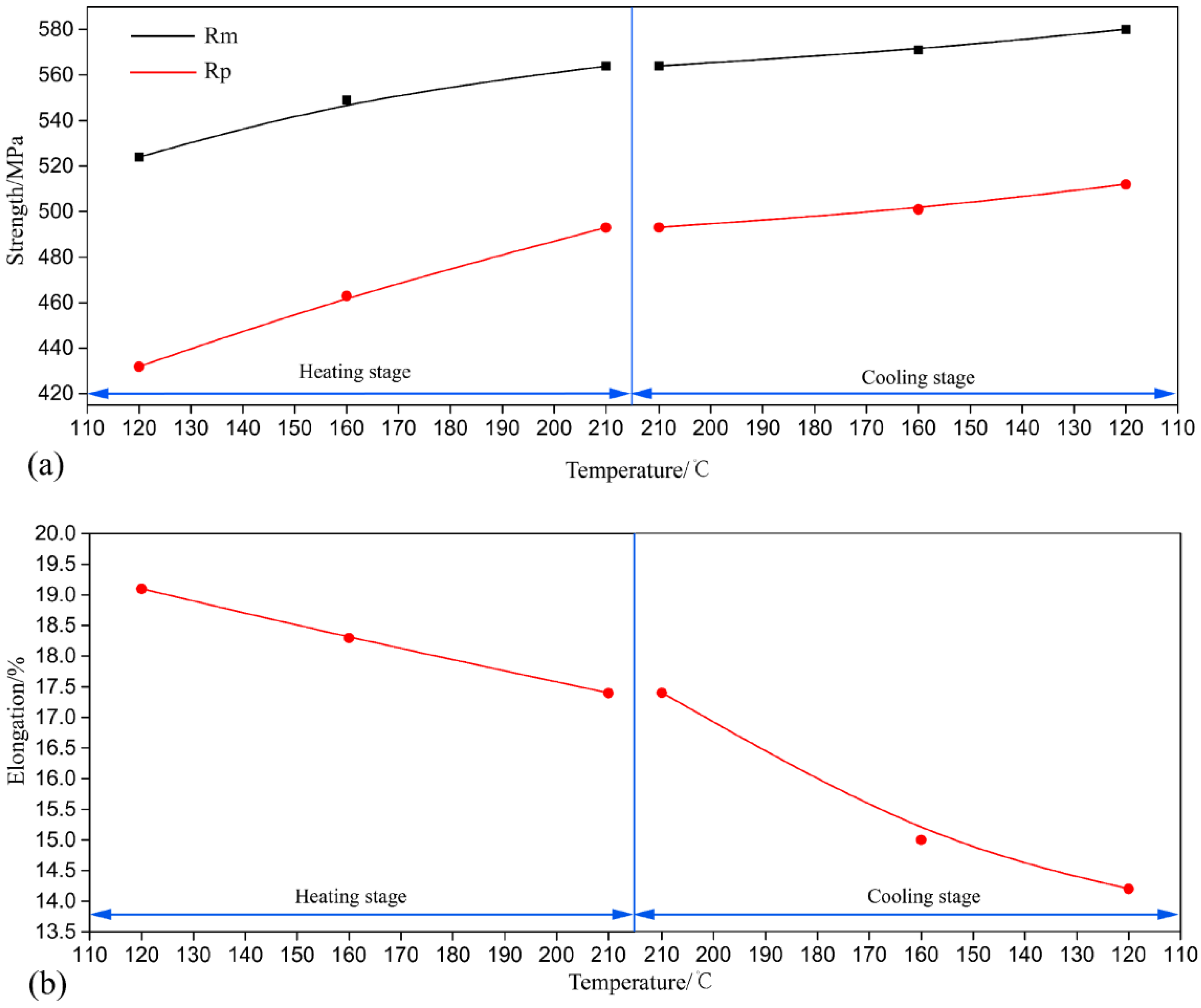
The tensile strength (Rm) and yield strength (Rp) displayed similar characteristics to the hardness evolution, as shown in Figure 3. The tensile strength and yield strength of the alloy increased whether during the heating stage or the cooling stage. During the heating stage, the tensile strength of the alloy increased from 511 MPa (Solid solution) to 524 MPa when the alloy was heated to 120 °C (H120). As the temperature increased from 120 °C to 210 °C, the tensile strength increased rapidly from 524 MPa to 564 MPa during the heating stage. In addition, it then slowly increased to 580 MPa during the cooling stage. The tensile strength increased by approximately 56 MPa during the aging process. Similarly, the yield strength value increased rapidly from 432 MPa to 493 MPa, and then slowly increased to 512 MPa as the aging process entered the cooling stage. The yield strength increased by approximately 80 MPa during the aging stage. In general, both tensile strength and yield strength increased both in the heating and in the cooling stage. However, the elongation of the alloy trend was reversed. The elongation value reduced from 19.1% to 17.4% during the heating stage, and then reduced to 14.2% as the aging process entered the cooling stage. The elongation decreased by approximately 4.9% during the aging stage.

3.2. Corrosion Resistance

Figure 4 reveals the corrosion surface morphology of the alloy with non-isothermal creeping aging by scanning electron microscope and ultra-depth three-dimensional microscope. It can be found from the SEM pictures that the most serious corrosion occurred in the sample of solid quenching. There was a large accumulation of powdery corrosion products, and there were a lot of bulges on the sample surface (Figure 4a). Conversely, the C120 specimen had the best corrosion resistance; the surface had a few corrosion products and the sample surface was slightly raised in a few places (Figure 4c). The ultra-depth three-dimensional microscope pictures were able to confirm the corrosion degree of the samples based on their roughness data. The maximum corrosion roughness of the solid quenched samples was 1018 μm (Figure 4a). In contrast, NICA samples featured better corrosion resistance, and their surfaces did not have a large number of high bumps on the surfaces compared to the solid solution samples. Compared to the corrosion resistance in the NICA process, the best corrosion resistance was C120, the surface of which had few corrosion products, and the maximum corrosion roughness was 430 μm (Figure 4c). However, in the other NICA process, the corrosion roughness was between 600 and 800 μm (Figure 4b,d–f), and the corrosion resistance was better than that of solid solution samples. In conclusion, the corrosion resistance order of samples was NICA, solid solution, quenching. The best samples treated by NICA were the C120 samples.

3.3. Microstructure Evolution during NICA

The mechanical properties and corrosion behavior of the alloy were greatly influenced by the microstructure. Herein, the precipitates of the interiorgrain and the characteristics of the grain boundary of the alloy with different aging treatments are characterized by TEM. Figure 5 shows the selected area diffraction pattern (SAED) and simulated patterns of GPI zones, and η and η′phases near the [100] axis. Diffraction pattern can effectively describe the evolution of precipitates during the NICA process. Slight diffraction at the {1, 3/4, 0} position and 1/2{020}, 1/2{220}, 1/2{200} positions can be observed with H120 in Figure 5a, where the spots at the {1, 3/4, 0} position were associated with GPI zones, and those at 1/2{020}, 1/2{220}, 1/2{200} positions were due to the precipitation of Al3Zr. This confirmed that GPI zones had formed. The slow diffusion rate of Zr, Al3Zr was preferentially formed in the matrix due to the solute atom segregation in the solid solution process. When continuously heated to 160 °C (Figure 5b), the type of diffraction pattern in the alloy was basically the same as that of H120, both of which had GPI zones and Al3Zr. However, weak spots reflected from the η′ phases were detected at 1/3 {220}, 2/3 {220} positions, suggesting that the η′ may be formed after being heated to 160 °C. Diffraction pattern changed significantly when the sample was heated to 210 °C, as shown in Figure 5c. The diffraction spots at 1/3 {220}, 2/3 {220} positions were obviously strengthened, and no diffraction features of the GPI zones and Al3Zr could be identified. As the aging temperature decreased to 160 °C (Figure 5d), GPI spots reappeared, whereas those from the η′ phases became stronger. On the other hand, weak spots reflected from the η phases were observed. Likewise, the spots from GPI zones and η, η′ phases were caught when further cooled to 120 °C (Figure 5e), and those from the η phases became stronger.
Figure 6 reveals the bright field TEM images during heating stage and cooling stage of NICA treatment, respectively. Precipitates were quite fine and dense when the sample was heated to 120 °C (H120), as shown in Figure 6a,b. These can be identified as GPI zones in Figure 6a. A high density of fine precipitates was also observed in the sample heated to 160 °C (H160), as shown in Figure 6c. The precipitates for strengthening were identified as mainly GPI zones with a small amount of η′ phase. When the sample was heated up to 210 °C (H210), precipitates of η′ phase grew distinctly larger, as shown in Figure 6d. Precipitate size became smaller when the sample was cooled to 160 °C (C160), as shown in Figure 6e. When the sample was cooled to the C120 condition, the main precipitates for strengthening were GPI zones and η and η′ phases, and the size of the precipitates decreased remarkably, as shown in Figure 6f. Moreover, it is worth mentioning that Al3Zr could only be observed in the sample of H160, which was consistent with the diffraction patterns shown in Figure 5. This phenomenon could be caused by heterogeneous precipitation of Al3Zr particles due to the low diffusion rate of Zr in the matrix [28].
It is well known that the properties of the alloy are greatly affected by the types, size, distribution and volume fraction of the precipitates. Herein, the radius and volume fraction of the precipitates in the alloy with NICA treatment were calculated by the method reported by Dumont et al. [29]. And the volume fraction of the precipitates were calculated as described in Appendix A. The results are shown in Figure 7. During the heating stage, the mean precipitation radius in this case increased sharply with the increase in temperature. The radius reached its maximum when the temperature reached 210 °C. Under cooling conditions, the average radius of the precipitate decreased until the aging temperature reached 120 °C. For the volume fraction of the precipitates in the alloy with NICA treatment, the volume fraction increased rapidly when the alloy was heated from 120 °C to 160 °C, and then decreased slightly when the alloy was heated to 210 °C. During the cooling stage, the volume fraction of the precipitates increased continuous and reached their maximum when cooled to a temperature of 120 °C. Hence, the enhanced mechanical properties of the alloy with the C120 treatment as shown in Figure 2 and Figure 3 could be caused by the finest and highest volume fraction of precipitates in the alloy.
Generally, the 7XXX alloys precipitation sequence is: SSS→GP zone→η’→η(MgZn2). NICA differs from traditional isothermal aging in many respects, such as dislocation produced by creeping and temperature history. Some of the precipitation of metastable phases should be activated during the NICA process. The precipitation process could be affected by diffusion, driving force, and nucleation barriers [30]. According to the theory proposed by Aaronson, the driving force for precipitation Δg could be expressed as follows [31]:
Δ g = κ T ν at ln ( C C eq )  
where νat represents the atomic volume of the precipitates, κ represents the Boltzman’s constant, T is the absolute temperature, Ceq is the equilibrium solute concentration, and C is the current solute concentration of the substrate. The critical radius (R) of the precipitates deduced from Equation (1) is as follows:
R * = 2 γ ν at κ Tln ( C / C eq )  
where γ is the interface energy of the precipitates. Based on the investigation of Wagner and Kampmann [32], precipitates with radii greater than R* are coarsened, and those with radii smaller than R* were dissolved into the matrix.
A tensile stress of 200 MPa was applied throughout the aging process when carrying out the NICA process, under which a dislocation is generated, and then pushed to the grain boundary. Owing toits phase error motion, the solute diffusion rate around the crystal boundary increased with the action of the channel diffusion path. Moreover, dislocation can be used as the diffusion path of the solute, which will reduce R*, thus promoting nucleation and growth of precipitates.
In the present case, a high supersaturation alloy could be produced by stepped solid solution treatment. When the supersaturation alloy was heated to 120 °C at a slow heating rate, a great majority of the fine GPI zone precipitated from the matrix, which was confirmed by the diffraction patterns and bright field images in Figure 5a and Figure 6a,b. When aging temperature kept increasing, the driving force for precipitation and the critical radius both increased. This led to a faster nucleation and precipitation process. The coarsening and dissolution of fine precipitates could also be accelerated due to the higher diffusion rate of higher aging temperature. Hence, the size of the precipitates increased remarkably, and the volume fraction of the precipitates decreased slightly in alloy with the H210 treatment, and the main precipitates for strengthening were the η′ phase.
During the cooling stage, the driving force for precipitation and the critical radius decreased. Amajority of particles could have been unstable due to their having a size larger than the critical radius. The dissolution of precipitates increased the concentration of excess solutes in the matrix and led to a secondary precipitation in alloys with C160 and C120 treatment. Herein, a diffraction pattern of GPI zone and η′ phase could be observed in Figure 6d,e (the diffraction patterns of the GPI zone disappeared in alloys with the H210 treatment in Figure 6c). Some particles with larger sizes could dissolve slowly, which could also be responsible for reducing the size of precipitates in the alloy. Hence, the size and the volume fraction of the precipitates was the smallest and maximum respectively in the alloy with C120 treatment due to the dissolution of lager particles and secondary precipitation. Moreover, the C120 sample had the highest hardness and improved tensile properties due to the finest and highest volume fraction of precipitates in the alloy.

3.4. Characteristics of Grain Boundary during NICA

In addition to the precipitates in the grain interior, the microstructure of the grain boundary also played an important role on the corrosion behavior of the alloy. Figure 8 shows grain boundary precipitation (GBPs) and precipitation-free zones (PFZs) in the alloy after NICA treatment. There were neither GBPs nor PFZs in the alloy after solid solution treatment, as shown in Figure 8a. Discontinuous coarse particles and PFZ could be observed in the alloy with NICA treatment, as shown in Figure 8b–f. However, the size of coarsened particles and the width of the PFZ in the alloy were different from each other. The size of coarse particles on the grain boundary first increased and then decreased when the alloy was cooled to 120 °C (C120). The width of PFZ in the alloy increased from 47 nm (H120) to 67 nm (C160), and then decreased to 50 nm when the alloy was cooled to 120 °C. To sum up, the smallest particles on the grain boundary and PFZ widths were formedin the alloy with C120 treatment (Figure 8f).
GBPs have been reported in many studies, and the potential differences between adjacent alloy matrices and PFZs have been reported in many studies [33,34]. On the one hand, in the heating stage (C120-C210), precipitates that had been continuously distributed at the boundary became effective corrosion pathways, and severe sensitiveness to peeling corrosion occurs. On the other hand, the separation of precipitate phases in the grain boundary was an anode to the aluminum matrix, so it could be easily preferentially corroded if the aluminum matrix was still stable. As for the cooling stage, not only were GBPs discontinuously distributed, but the size and voids also became larger. The corrosion path cut off and the corrosion rate was reduced, thus reducing the spalling corrosion. In addition, because the width of PFZ was affected by the aging system, the formation of PFZ was related to the smaller areas of atoms adjacent to the grain boundary [35]. Consistent with the research observations of Li [36] and Peng [20], narrowing PFZ was beneficial to the improvement of corrosion resistance. In general, PFZ expanded by increasing aging temperature and increasing aging time to form, grow and roughen solution atoms containing GBPs. Under the conditions of C160, PFZ expanded again, but the coarse GBPs were not continuously distributed at the grain boundary. However, under the C120 conditions, the new fine precipitates narrowed the PFZ, but the coarse, spaced GBPs were still discontinuously distributed at the grain boundary. Therefore, the corrosion resistance was further enhanced. These studies show that alloys treated with NICA have high strength and desired corrosion resistance.

4. Conclusions

This paper studied the precipitate behavior, mechanical properties and corrosion behavior of an Al-Zn-Mg-Cu alloy with non-isothermal creep aging treatment. The main conclusions were as follows:
  • The hardness and tensile strength generally kept growing with increasing aging time until the level of 185 HV and 580 MPa (C120). During the heating stage, GPI zones precipitated from the matrix firstly at the aging condition of H120, and then the major precipitates became η′phases with the increase of aging temperature to 210 °C (H210). Moreover, both the size and volume fraction of the precipitates increased. Hence, the tensile strength and hardness of the NICA processing technology increased during the heating stage. Furthermore, in the cooling process, coarse precipitates in the grain interior began to dissolve, and GPI zones and η′phases precipitated from the matrix secondarily. The size of the precipitates was greatly decreased, and the volume fraction reached a maximum, which led to peak hardness and tensile strength of the alloy.
  • The alloy treated with NICA had the highest corrosion resistance in C120. In the cooling phase, the dissolution of precipitates caused the PFZ to narrow due to the secondary precipitation of new fine precipitates, but the coarse GBPs were not continuously distributed in the grain boundary, which further improved corrosion resistance.
  • To reduce heat treatment process time and the manufacturing cost of Al-Zn-Mg-Cu alloy overall panel components, the NICA process was designed, which only lasted about 13 h without loss of alloy properties. Therefore, compared with the traditional aging process, the manufacturing cost was greatly decreased.

Author Contributions

The conceptualization was designed by J.Z. and B.J. The methodology was designed and improved by all authors (J.Z., B.J., D.Y., H.W., and G.W.). The formal analysis, investigation, and validation were carried out by all authors (J.Z., B.J., D.Y., H.W., and G.W.). The writing of the original draft was prepared by J.Z. The review and editing of the manuscript was made by all authors (J.Z., B.J., D.Y., H.W., and G.W.). The supervision was made by D.Y. All authors have read and agreed to the published version of the manuscript.

Funding

This research received no external funding.

Conflicts of Interest

The authors declare no conflict of interest. The funders had no role in the design of the study; in the collection, analyses, or interpretation of data; in the writing of the manuscript, or in the decision to publish the results.

Appendix A

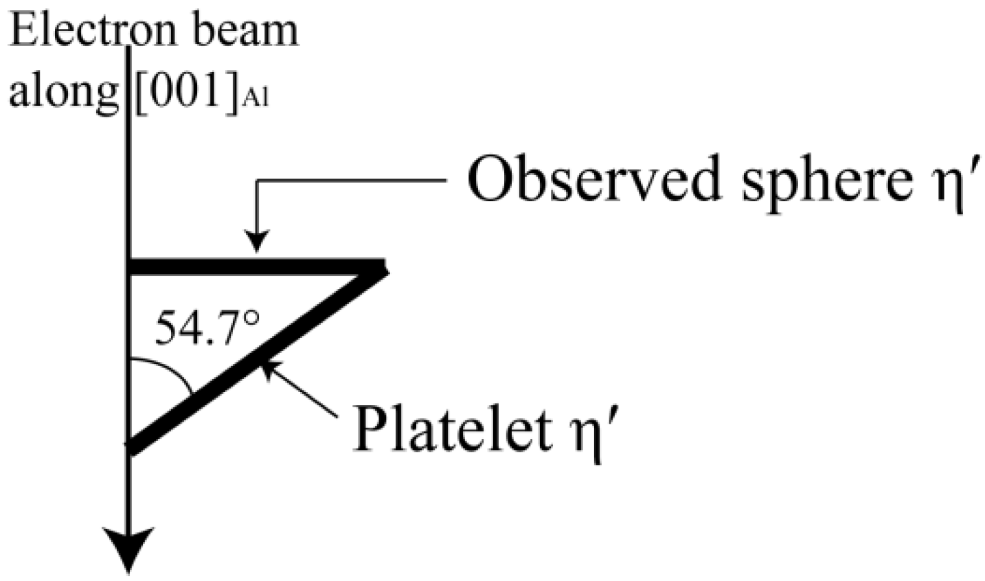
η′ are observed as platelets with (0001)η′ parallel to the (111)Al planes. There are four variants for η′ phase. When observed along [001]Al axes, all variants are at an angle of 54.7° [37] with the electron beam, as shown in Figure A1.
Figure A1. Schematic diagram of angle between variants and the electron beam along [001]Al axes.
Metals 10 00378 g0a1
The observed “sphere” η′ is a fake image, and the real diameter of platelet η′ can be calculated as follows [38]:
Dη′ = Dη′sphere/sin(54.7°)
where Dη′ represents the real average diameter of platelet η′, and Dη′sphere is the average diameter of observed sphere η′. The average diameter and number of precipitates were obtained from the bright field image of Figure 6. The volume fraction is calculated as follows:
fv = Vt/Vfoil
where Vt is the total volume of η′ particles, Vfoil is the volume of the observed area. Vt can be calculated as follows:
Vt = Nη′*Vη′
where Nη′ is the number of η′ particles in the observed area, Vη′ is the volume of a single η′ particle. The Vη′ can be calculated as follows:
V η = π TD η 2 4
where T is the thickness of η′, it was proposed to be T≈0.38 Dη′ by Dumont [29].
The Vfoil was obtained using the follow equation:
Vfoil = As*t
where As and t are the area and thickness of the observed area, respectively. The bright field images were obtained at approximately 0.75 μm (the distance between the observed area and the hole) from the hole of the foil. According to the linear relationship of the distance from the hole and sample thickness from Dumont [29], the foil thickness was 48 nm in the present case.
Finally, the volume fraction is obtained.

References

  1. Zhang, Y.D.; Jin, S.B.; Trimby, P.W.; Liao, X.Z.; Murashkin, M.Y.; Valiev, R.Z.; Liu, J.Z.; Cairney, J.M.; Ringer, S.P.; Sha, G. Dynamic precipitation, segregation and strengthening of an Al-Zn-Mg-Cu alloy (AA7075) processed by high-pressure torsion. Acta Mater. 2019, 162, 19–32. [Google Scholar] [CrossRef]
  2. Yuan, D.; Chen, K.H.; Chen, S.Y.; Zhou, L.; Chang, J.Y.; Huang, L.P.; Yi, Y. Enhancing stress corrosion cracking resistance of low Cu-containing Al-Zn-Mg-Cu alloys by slow quench rate. Mater. Des. 2019, 164, 107558. [Google Scholar] [CrossRef]
  3. Xie, P.; Chen, S.Y.; Chen, K.H.; Jiao, H.B.; Huang, L.P.; Zhang, Z.; Yang, Z. Enhancing the stress corrosion cracking resistance of a low-Cu containing Al-Zn-Mg-Cu aluminum alloy by step-quench and aging heat treatment. Corros. Sci. 2019, 161, 108184. [Google Scholar] [CrossRef]
  4. Dumont, D.; Deschamps, A.; Brechet, Y. On the relationship between microstructure, strength and toughness in AA7050 aluminum alloy. Mater. Sci. Eng. A 2013, 356, 326–336. [Google Scholar] [CrossRef]
  5. Wang, S.S.; Jiang, J.T.; Fan, G.H.; Frankel, G.S.; Zhen, L. Effects of long-term natural aging on the altered surface layer on an Al-Zn-Mg-Cu alloy and on corrosion properties. Electrochim. Acta 2018, 266, 34–42. [Google Scholar] [CrossRef]
  6. Zhao, H.; De Geuser, F.; Kwiatkowski, A.; Silva, D.; Szczepaniak, A.; Gault, B.; Ponge, D.; Raabe, D. Segregation assisted grain boundary precipitation in a model Al-Zn-Mg-Cu alloy. Acta Mater. 2018, 156, 318–329. [Google Scholar] [CrossRef] [Green Version]
  7. Sha, G.; Cerezo, A. Kinetic Monte Carlo simulation of clustering in an Al–Zn–Mg–Cu alloy (7050). Acta Mater. 2005, 53, 907–917. [Google Scholar] [CrossRef]
  8. Deschamps, A.; De Geuser, F.; Horita, Z.; Lee, S.; Renou, G. Precipitation kinetics in a severely plastically deformed 7075 aluminium alloy. Acta Mater. 2014, 66, 105–117. [Google Scholar] [CrossRef] [Green Version]
  9. Chen, S.Y.; Chen, K.H.; Peng, G.S.; Chen, X.H.; Ceng, Q.H. Effect of heat treatment on hot deformation behavior and microstructure evolution of 7085 aluminum alloy. J. Alloys Compd. 2012, 537, 338–345. [Google Scholar] [CrossRef]
  10. Berg, L.K.; Gjønnes, J.; Hansen, V.; Li, X.Z.; Knutson-Wedel, M.; Waterloo, G.; Schryvers, D.; Wallenberg, L.R. GP-zones in Al–Zn–Mg alloys and their role in artificial aging. Acta Mater. 2001, 49, 3443–3451. [Google Scholar] [CrossRef]
  11. Sha, G.; Cerezo, A. Early-stage precipitation in Al–Zn–Mg–Cu alloy (7050). Acta Mater. 2004, 52, 4503–4516. [Google Scholar] [CrossRef]
  12. Stiller, K.; Warren, P.J.; Hansen, V.; Angenete, J.; Gjønnes, J. Investigation of precipitation in an Al–Zn–Mg alloy after two-step ageing treatment at 100 °C and 150 °C. Mater. Sci. Eng. A 2004, 270, 55–63. [Google Scholar] [CrossRef]
  13. Cao, F.H.; Zheng, J.X.; Jiang, Y.; Chen, B.; Wang, Y.R.; Hu, T. Experimental and DFT characterization of η′ nano-phase and its interfaces in AlZnMgCu alloys. Acta Mater. 2019, 164, 207–219. [Google Scholar] [CrossRef]
  14. Gjønnes, J.; Simensen, C.J. An electron microscope investigation of the microstructure in an aluminium-zinc-magnesium alloy. Acta Metall. 1970, 18, 881–890. [Google Scholar] [CrossRef]
  15. Zhan, X.; Tang, J.G.; Li, H.Z.; Liang, X.P.; Zhang, Y. Effects of non-isothermal aging on mechanical properties, corrosion behavior and microstructures of Al-Cu-Mg-Si alloy. J. Alloys Compd. 2020, 819, 152960. [Google Scholar] [CrossRef]
  16. Jiang, J.T.; Xiao, W.Q.; Yang, L.; Shao, W.Z.; Yuan, S.J.; Zhen, L. Ageing behavior and stress corrosion cracking resistance of a non-isothermally aged Al–Zn–Mg–Cu alloy. Mater. Sci. Eng. A 2014, 605, 167–175. [Google Scholar] [CrossRef]
  17. Jiang, J.T.; Tang, Q.J.; Yang, L.; Zhang, K.; Yuan, S.J.; Zhen, L. Non-isothermal ageing of an Al–8Zn–2Mg–2Cu alloy for enhanced properties. J. Mater. Process. Technol. 2016, 227, 110–116. [Google Scholar] [CrossRef]
  18. Peng, X.Y.; Guo, Q.; Liang, X.P.; Deng, X.P.; Guo, Y.; Xu, G.F.; Yin, Z.M. Mechanical properties, corrosion behavior and microstructures of a non-isothermal ageing treated Al-Zn-Mg-Cu alloy. Mater. Sci. Eng. A 2017, 688, 146–154. [Google Scholar] [CrossRef]
  19. Zhang, J.; Wang, Y.; Deng, Y.; Zhang, X. Effect of deformation degree on the creep age forming of 7475 aluminum alloy: The feasibility of the extended deformation range. Mater. Sci. Eng. A 2016, 664, 126–134. [Google Scholar] [CrossRef]
  20. Zheng, J.; Davies, C.M.; Lin, J.; Pan, R.; Li, C. Constitutive modelling of a T74 multi-step creep ageing behaviour of AA7050 and its application to stress relaxation ageing in age formed aluminium components. Procedia Eng. 2016, 207, 281–286. [Google Scholar] [CrossRef]
  21. Xu, Y.Q.; Zhang, L.H.; Huang, M.H.; Shen, R.L.; Ma, Z.Y.; Xu, L.Z.; Wang, K.; Wang, X. Deformation behavior of Al-Cu-Mg alloy during non-isothermal creep age forming process. J. Mater. Process. Technol. 2018, 255, 26–34. [Google Scholar] [CrossRef]
  22. Zhan, L.H.; Lin, J.G.; Dean, T.A. A review of the development of creep age forming: Experimentation, modelling and applications. Int. J. Mach. Tools Manuf. 2011, 51, 11–17. [Google Scholar] [CrossRef]
  23. Jeunechamps, P.P.; Ho, K.C.; Lin, J.; Ponthot, J.P.; Dean, T.A. A closed form technique to predict springback in creep age-forming. Int. J. Mech. Sci. 2006, 48, 621–629. [Google Scholar] [CrossRef]
  24. Jeshvaghani, R.A.; Shahverdi, H.R.; Hadavi, S.M.M. Investigation of the age hardening and operative deformation mechanism of 7075 aluminum alloy under creep forming. Mater. Sci. Eng. A 2012, 552, 172–178. [Google Scholar] [CrossRef]
  25. Lin, Y.C.; Jiang, Y.Q.; Chen, X.M.; Wen, D.X.; Zhou, H.M. Effect of creep-aging on precipitates of 7075 aluminum alloy. Mater. Sci. Eng. A 2013, 588, 347–356. [Google Scholar] [CrossRef]
  26. Chen, J.F.; Zhen, L.; Jiang, J.T.; Yang, L.; Shao, W.Z.; Zhang, B.Y. Microstructures and mechanical properties of age-formed 7050 aluminum alloy. Mater. Sci. Eng. A 2012, 539, 115–123. [Google Scholar] [CrossRef]
  27. Standard, A. G34-01: Standard Test Method for Exfoliation Corrosion Susceptibility in 2XXX and 7XXX Series Al Alloys; ASTM International: West Conshohocken, PA, USA, 2001. [Google Scholar]
  28. Zhang, W.; Xing, Y.; Jia, Z.H.; Yang, X.F.; Liu, Q.; Zhu, C.L. Effect of minor Sc and Zr addition on microstructure and properties of ultra-high strength aluminum alloy. Trans. Nonferrous Met. Soc. China 2014, 24, 3866–3871. [Google Scholar] [CrossRef]
  29. Dumont, M.; Lefebvre, W.; Doisneau-Cottignies, B. Characterisation of the composition and volume fraction of η′ and η precipitates in an Al–Zn–Mg alloy by a combination of atom probe, small-angle X-ray scattering and transmission electron microscopy. Acta Mater. 2005, 53, 2881–2892. [Google Scholar] [CrossRef]
  30. Nicolas, M.; Deschamps, A. Characterisation and modelling of precipitate evolution in an Al–Zn–Mg alloy during non-isothermal heat treatments. Acta Mater. 2003, 51, 6077–6094. [Google Scholar] [CrossRef] [Green Version]
  31. Aaronson, H.I.; Kinsman, K.R.; Russell, K.C. The volume free energy change associated with precipitate nucleation. Scr. Metall. 1970, 4, 101–106. [Google Scholar] [CrossRef]
  32. Wagner, R.; Kampmann, R. Stabilität bei geraden Stäben. J. Mater. Sci. Technol. 1991, 5, 213. [Google Scholar]
  33. Yang, W.C.; Ji, S.X.; Zhang, Q.; Wang, M.P. Investigation of mechanical and corrosion properties of an Al–Zn–Mg–Cu alloy under various ageing conditions and interface analysis of η′ precipitate. Mater. Des. 2015, 85, 752–761. [Google Scholar] [CrossRef] [Green Version]
  34. Li, J.H.; Li, F.G.; Ma, X.K.; Li, J.; Liang, S. Effect of grain boundary characteristic on intergranular corrosion and mechanical properties of severely sheared Al-Zn-Mg-Cu alloy. Mater. Sci. Eng. A 2018, 732, 53–62. [Google Scholar] [CrossRef]
  35. Sun, X.Y.; Zhang, B.; Lin, H.Q.; Zhou, Y.; Sun, L.; Wang, J.Q.; Han, E.H.; Ke, W. Correlations between stress corrosion cracking susceptibility and grain boundary microstructures for an Al–Zn–Mg alloy. Corros. Sci. 2013, 77, 103–112. [Google Scholar] [CrossRef]
  36. Qi, H.; Liu, X.Y.; Liang, S.X.; Zhang, X.L.; Cui, H.X.; Zheng, L.Y.; Gao, F.; Chen, Q.H. Mechanical properties and corrosion resistance of Al–Cu–Mg–Ag heat-resistant alloy modified by interrupted aging. J. Alloys Compd. 2016, 657, 318–324. [Google Scholar] [CrossRef]
  37. Huang, J.C.; Ardell, A.J. Crystal structure and stability of T 1 precipitates in aged Al–Li–Cu alloys. Mater. Sci. Technol. 1987, 3, 176–188. [Google Scholar] [CrossRef]
  38. Dorin, T.; Donnadieu, P.; Chaix, J.M.; Lefebvre, W.; Geuser, F.D.; Deschamps, A. Size distribution and volume fraction of T1 phase precipitates from TEM images: Direct measurements and related correction. Micron 2015, 78, 19–27. [Google Scholar] [CrossRef]
Figure 1. Schematic diagram of the heat treatment processing for the 7075 Al alloy: “H120”, “H160”, “H210”, “C160”, “C140” and “C120” are short for “Heated at 120 °C”, “Heated at 160 °C”, “Heated at 210 °C”, “Cooled at 160 °C”, “Cooled at 140 °C”, “Cooled at 120 °C”, respectively.
Metals 10 00378 g001
Figure 2. Microhardness variations of the Al-Zn-Mg-Cu alloy during the NICA process.
Metals 10 00378 g002
Figure 3. Mechanical properties of the Al-Zn-Mg-Cu alloy during the NICA process: (a) strength; (b) elongation.
Metals 10 00378 g003
Figure 4. The SEM and the ultra-depth three-dimensional microscope diagram of the Al-Zn-Mg-Cu alloy: (a) Solid solution; (b) H210; (c) C120; (d) H120; (e) H160; (f) C160.
Metals 10 00378 g004
Figure 5. SAED patterns of the Al-Zn-Mg-Cu alloy during the cooling stage of the NICA process: (a) H120; (b) H160; (c) H210; (d) C160; (e) C120; (f) Simulated SAED pattern.
Metals 10 00378 g005
Figure 6. Intragranular TEM images of the Al-Zn-Mg-Cu alloy during the heating stage of the NICA process: (a) and (b) H120; (c) H160; (d) H210; (e) C160; (f) C120.
Metals 10 00378 g006
Figure 7. Simulation results of the Al-Zn-Mg-Cu alloy during the NICA process: (a) average precipitate radius; (b) precipitate volume fraction.
Metals 10 00378 g007
Figure 8. Intragranular TEM images of the Al-Zn-Mg-Cu alloy during the heating stage of the NICA process: (a) solid solution; (b) H120; (c) H160; (d) H210; (e) C160; (f) C120.
Metals 10 00378 g008
Table 1. Chemical composition of as-received Al-Zn-Mg-Cu alloy (wt%).
ZnMgCuZrSiFeAl
5.662.641.820.090.160.08Bal.