Article

Effect of Current Input Method on A356 Microstructure in Electromagnetically Stirred Process

1
Company of Hanju Metal, 753-20 Wonsan Ulsan, Korea
2
School of Mechanical Engineering, Pusan National University, 609 735 Busan, Korea
3
School of Mechanical Engineering, Kyungnam University, 7 Kyungnamdaehak-ro, Masanhappo-gu, Changwon-si, 51767 Gyeongsangnam-do, Korea
*
Author to whom correspondence should be addressed.
Metals 2020, 10(4), 460; https://doi.org/10.3390/met10040460
Submission received: 10 March 2020 / Revised: 27 March 2020 / Accepted: 30 March 2020 / Published: 2 April 2020
(This article belongs to the Special Issue Microstructural Engineering in Metallic Materials)

Abstract

:
This paper focuses on the electromagnetically stirred process for manufacturing the material required for the semi-solid forming method. The maximum weight of the molten metal used at a laboratory scale in the currently published research is 3 kg. However, a large-scale electromagnetic device is needed when using a material with a maximum weight of 5 kg or more of the molten metal used in the actual industry. Therefore, controllers in this study are installed at each pole in the electromagnetic stirrer, which has six poles in order to stir materials weighing 5 kg or more. The current is input to the adjacent pole counterclockwise (CAMP), and to the symmetrical poles counterclockwise (CSMP). The experiment results show that the current method input to the CSMP can generate the highest electromagnetic force at the center of molten metal. A phase analysis is performed for the size and the roundness of primary α-Al particle from the material prepared by different input currents. The degree of roundness of primary α-Al particles is better when the current is input to the symmetrical poles counterclockwise.

1. Introduction

A semi-solid alloy manufacturing process which is a new structural metal material technology is gaining worldwide attention as a new metal processing field, along with the development strategies of low-polluting process technology and energy-saving lightweight materials which resolve environmental and energy issues. Particularly, lightweight components using aluminum alloys as lightweight materials are being developed mainly by directly forming liquid materials into a desired shape: from liquid states, such as diecasting and molten forging, or forging which manufactures components from solid materials. In particular, research on A356 is increasing in recent industries. A356 material has good fluidity in the solid-liquid coexistence zone and its mechanical strength can be improved through heat treatment. Therefore, it is used for parts requiring strength and reliability such as knuckles, arms and housings of automobiles. In particular, the mechanical properties of A356 are closely related to the size of primary α-Al particles, secondary dendrite arm spacing (SDAS), and the distribution of Si particles in the process [1,2].
However, in the casting process, there are defects caused by capturing air, shrinkage due to the turbulence of the material, and shortening of the life of the mold due to overheating of the molten metal when the molten metal flows into the cavity [3,4]. In addition, it is difficult to produce precision parts requiring high forming pressure, as well as to address loss of productivity and economic feasibility due to post-processing such as cutting in the forging process [5].
In order to solve this problem, it is necessary to break down the dendrite structure to create a spherical shape by agitation during solidification in the liquid and solid phases, and to produce an alloy having a uniform microstructure. A process technology to form products by using the rheology characteristics of the material by re-heating the billet to semi-molten state is likewise required. The semi-solid working method is a compound processing method that combines casting and forging. It has been developed from MIT [6] in 1971 and identified as rheocasting [7,8], thixocasting [9,10], or stircasting. Today’s semi-solid forming [11,12,13,14] can be classified into two types: rheocasting and thixoforming. Rheocasting produces the final product by directly forming the slurry produced in the semi-solid state whereas thixoforming manufactures a billet, having a spherical, non-branched microstructure cast in a semi-solid state, and then reheats the slug cut to a suitable length or into a semi-solid state to be forged or die casted into a final product. Electromagnetically stirred forming employing such a billet has a shorter solidification time than a method of molding in a liquid phase having a pure dendrite phase, thereby reducing shrinkage defects.
The rheology forming process, using electromagnetic stirring among the semi-solid forming methods, controls the dendritic structure by the solid stirring of molten metal in the initial stage of solidification, uniformly disperses it as superfine solid particles that are close to a spherical shape, and then forms it into a slurry with solid and liquid coexisting to be injected the product and into the cavity of mold in the forming machine. The electromagnetic stirred forming using the billet has a shorter solidification time than the forming method in a liquid phase possessing a pure dendrite phase, thereby lessening shrinkage defects [15]. Until now, researches have been conducted on agitation parameters that can control the grains of the aluminum semi-solid slurry using an electromagnetic stirring method. In actual research results, the equivalent diameter and roundness of solid particles were changed according to the stirring conditions. Semi-solid slurries applied with electromagnetic stirring showed a significantly smaller solid particle and lower roundness compared to slurries without electromagnetic stirring [16,17,18,19,20,21,22]. In response reology forming, ultrafine particles that are close to spherical can be obtained instead of the coarse resinous tissue present in ordinary castings, so they are highly fluid, having low strain resistance and good mechanical material properties.
The research published so far investigated the degree of roundness when electromagnetically stirring a melt of 3 kg [23,24] or less on a laboratory scale. However, research results related to the size and roundness of primary α-Al particle by current input method have not been published. Therefore, a large electromagnet for stirring the maximum weight of the molten metal by more than 5 kg with the total outer diameter of ∅ 600 mm, inner diameter of ∅ 145 mm, and height of 260 mm was utilized in this study. A controller was installed in each pole of the six-pole electromagnetic stirrer to change the current input direction. The electromagnetic force, according to the position of the magnetic stirrer, was measured and analyzed for the size and roundness of the primary α-Al particles according to the current input method.

2. Experiment

2.1. Preparation of Tool and Material

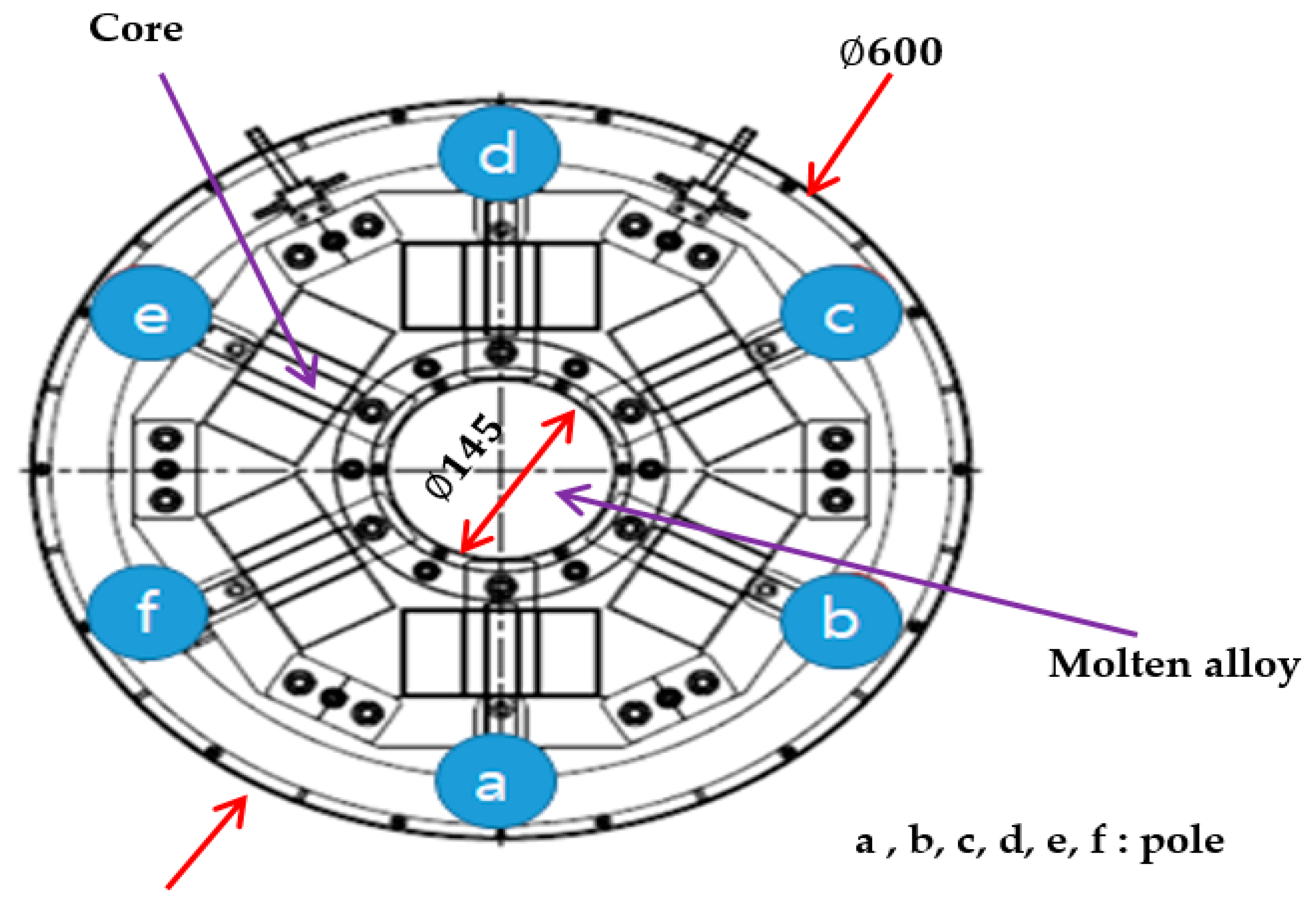
2.1.1. Electromagnetic Stirrer

Table 1 shows key specifications of the electromagnetic stirrer used for this study. The electromagnetic stirrer used in this study is a vertical type, large electromagnetic stirrer fabricated to have six poles. Air cooling was adopted for cooling the material. The core was fabricated using a silicon steel plate with a thickness of 40 mm and with a rectangular copper coil wound horizontally around the core. A vertical stirrer was then fabricated by installing six controllers at each pole to convert the pole into a + pole and a – pole, so that the current input direction could be changed. The total outer diameter of the electromagnet was ∅ 600 mm, the inner diameter ∅ 145 mm, the height 260 mm, and the total weight of the electromagnet 190 kg. A large electromagnet was manufactured to stir the maximum weight of the molten metal heavier than 5 kg.
Figure 1 shows the structure and actual scheme of the electromagnetic stirrer. The symbols ⓐ, ⓑ, ⓒ, ⓓ, ⓔ, and ⓕ represent six poles. Since each pole was positioned in the circumferential direction in the stirrer and the coil was wound in the vertical direction, the electromagnetic field was formed in the horizontal circumferential direction when a current was applied. The output type of the stirrer was a current control method.
Figure 2 is a schematic diagram of the crucible used in the experiment. Figure 2 shows the position where the electromagnetic force was measured using a Gauss meter. The crucible should not melt or deform at temperatures above 700 °C and should not be affected by electromagnetic forces. The size of the stirring container was prepared by referring to the results of this study. Six points were defined to identify the difference between magnetic flux density and microstructure of the center and surface of the electromagnet. Points ①, ② and ③ are the center of the electromagnet, and points ④, ⑤, ⑥ indicate the surface area.

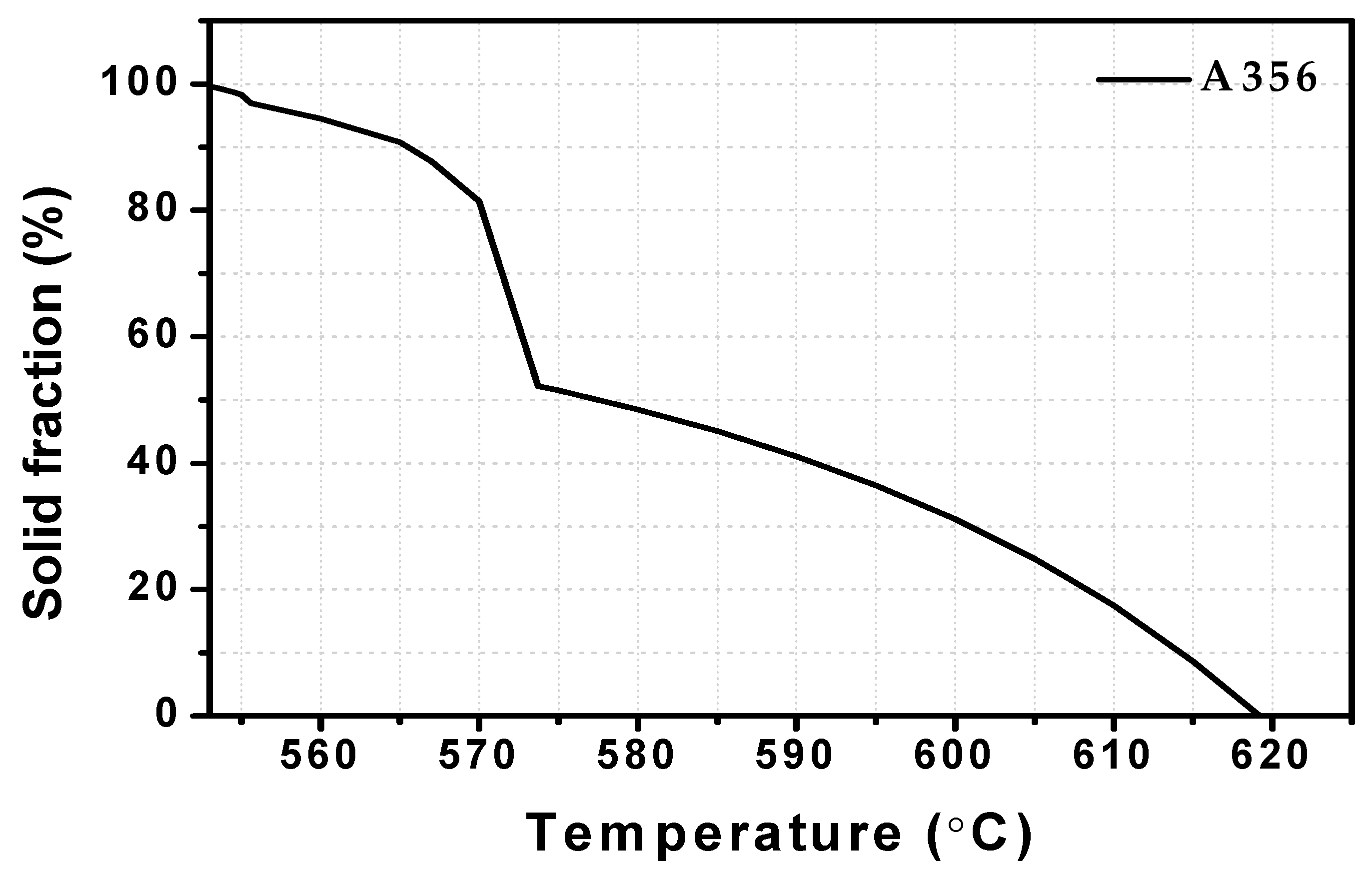
2.1.2. Material for Semi-Solid Surry

The material used in the experiment of semi-solid slurry preparation is A356, an aluminum alloy for casting with a high solid-liquid coexistence zone. Table 2 shows the composition of the A356 alloy. The solid fraction graph of the A356 material used in the experiment is shown in Figure 3 using the J Mat Pro program. The liquidus and solidus temperatures of the material are 553 °C and 617 °C, respectively, and the solidification range is 67 °C as indicated by the changes of the solid fraction graph.

2.2. Experimental Method

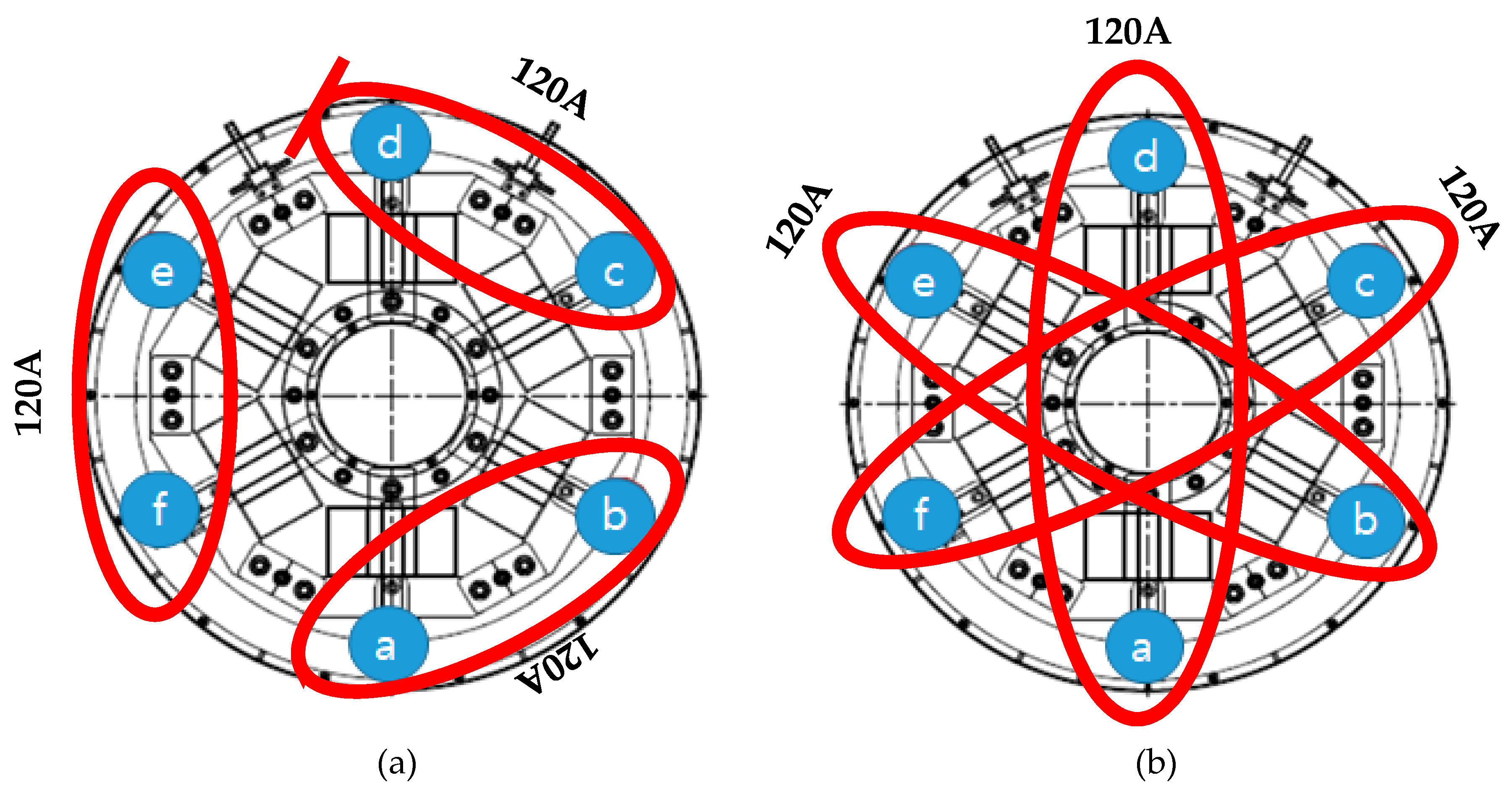
2.2.1. Method of Setting Current Input

In this study, the main variable of the electromagnetic stirring experiment is the current input method. Using the controller installed on each of the six poles, the current input method was switched by changing it to the + pole and − pole. Table 3 and Figure 4 shows the various current input methods.
For current input to adjacent poles counterclockwise simultaneously in the CAMP of Table 2 number (1), + was input to ⓐ, ⓒ, ⓔ, − was input to ⓑ, ⓓ, ⓕ, and the current was input to poles adjacent to each other in the order of ⓐⓑ→ⓒⓓ→ⓔⓕ. To input the current to the symmetrical poles counterclockwise simultaneously in the CSMP of Table 2 number (2), + current was input to ⓐ, ⓑ, ⓒ in Figure 4b and − current was input to ⓓ, ⓔ, ⓕ, in the order of ⓐⓓ→ⓑⓔ→ⓒⓕ. The relationship between current intensity and magnetic flux density were investigated for location as shown in Figure 2 using a Gauss meter.

2.2.2. Manufacturing Method of Semi-Solid Material

Figure 5 shows a process for preparing a semi-solid slurry using electromagnetic stirring. The manufacturing sequence explains how the six poles were operated using the controller when the material was stirred first by electromagnetic stirring process. After the crucible was inserted into the stirrer, the stirring was started simultaneously at the time of injecting the crucible. The temperature was measured by inserting a thermocouple in the center of the filled molten metal. The temperature of the molten metal in a thermal furnace was 700 °C and the temperature of the molten metal injected into a crucible was 640 °C. The stirring was stopped when the desired stirring time was reached. The semi-solid slurry was cooled at room temperature. Table 4 shows a condition in which semi-solid slurry is manufactured using a symmetric pole simultaneous input method and adjacent pole simultaneous input method with the greatest magnetic flux density of the current input method.
During stirring, gas or other substances could penetrate the material due to the inflow of external air and heat transfer; thereby, an oxide film was formed on the upper part of the slurry. In addition, since the molten metal rotated due to the stirring force, pores were generated in the center of the slurry. These act as defects inside the product, causing deterioration of its mechanical properties [15].
Therefore, the slurry produced by each stirring force was cut in the vertical direction to observe the center, as well as the surface, of the cross section. Figure 5 shows the photos of the cut slurry and locations of the microstructures in order to compare the changes in the structure of the simultaneous current input to the symmetric poles counterclockwise and simultaneous current input to the adjacent poles counterclockwise where the magnetic flux densities were the largest, and the unstirred semi-solid slurry had the highest magnetic flux density. The microstructure observation method first cut the specimen, went through the mounting and polishing process, followed by etching 35 g of FeCl3 35 g (200 mL of water) and HNO3 in turn and observing the micro-organization using optical microscope. In this study, the microstructure is measured and captured by optical microscope-BX53M model—with the detailed information about the microscope listed in Table 5. A Vickers hardness tester was used to investigate the mechanical properties of the semi-melt slurry to which electronic stirring was applied. The hardness tester used in this paper is the HM-100 model from Mitutoyo. Pyramid type diamond indenter (marker) is pressed against the surface of the material to make a pit, and it is expressed as the value obtained by dividing the surface area of the permanent pit remaining after removing the load. The hardness of the semi-melt slurry to which electronic stirring was applied was measured three times at six positions of the cross section as shown in Figure 5. In the section where the electronic agitation occurs, the magnetic flux density of the central and surface parts of the slurry is different, and the cooling rate is different, so the mechanical properties will be different.

3. Experimental Results

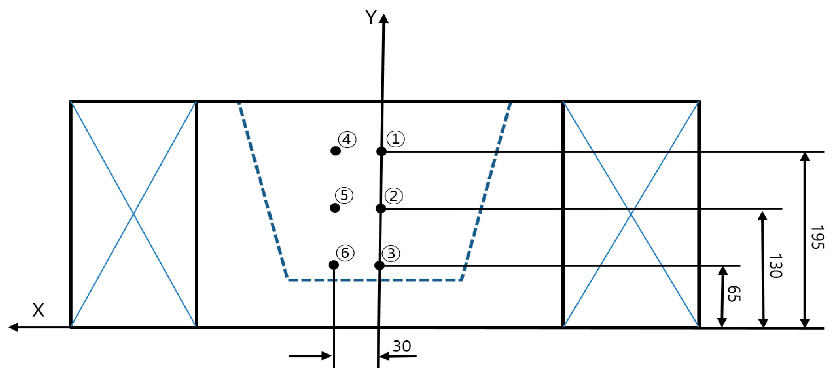
3.1. Comparison of Magnetic Flux Density

Figure 6 shows the values obtained by measuring the magnetic flux density of the electromagnetic stirrer for the current input method by means Gauss meter. As the agitation current increased, the magnetic flux density increased proportionally. The maximum magnetic flux density of the upper part (Position ①) and the lower part (Position ④) of the stirrer was 680 Gauss and 859 Gauss, respectively, whereas the maximum magnetic flux density ofthe stirrer was confirmed as 751 Gauss and 972 Gauss at the center of the stirrer (Position③, ⑤). The maximum magnetic flux density of the stirring method of CAMP in Table 2 was 665 Gauss, while the maximum magnetic flux density of the stirring method of CSMP in Table 2 was 972 Gauss. It was confirmed that the magnetic flux densities of the simultaneous current input to the symmetric poles were moving counterclockwise and such simultaneous current input to the symmetry poles counterclockwise, which was the input methods of CAMP and CSMP in Table 2, yielded the greatest effect.
The maximum magnetic flux density of the stirring method of CAMP in Table 2 was 665 Gauss, and the maximum magnetic flux density of the stirring method of CSMP in Table 2 was 972 Gauss. It was confirmed that the magnetic flux densities of the simultaneous current input to the symmetric poles counterclockwise and the simultaneous current input to the symmetry poles counterclockwise, which were the input methods of CAMP and CSMP in Table 2, yielded the greatest effect.

3.2. Analysis of Microstructure

Figure 7 shows microstructure observations of the surface portion and the central portion of the semi-solid slurry cross section. The slurries of simultaneous currents, having the largest magnetic flux densities and unstirred semi-solid slurry input to the symmetrical poles counterclockwise and simultaneous currents input to the adjacent polescounterclockwise having the largest magnetic flux densities and unstirred semi-solid were compared. It was observed in this study that by air-cooling the semi-solid slurries, generally complete dendrite structure was not formed. The solid particles and liquid (liquid-phase) particles in the semi-solid slurries became primary α-Al particle and eutectic structure, respectively, at room temperature after cooling only when the slurry was cooled in water. After the slurry was cooled in water, the solid particles and the liquid (liquid phase) in the semi-solid slurry became primary α-A particles and eutectic structure at room temperature. Due to the slow cooling rate, all aluminum particles were bound together by diffusion. Slurries which were electromagnetically stirred had a spherical form compared to the slurry which was not stirred. The simultaneous current input to the symmetrical poles improved in roundness compared to the simultaneous current input to the adjacent poles. In addition, the shape of the particles in the microstructure at the central part of the slurry was spherical and elliptical.It was also confirmed that the microstructure on the surface of the cross section was somewhat irregular, and that the solid particles here were relatively larger than the particles in the central portion.
Figure 8 shows the mean diameters and roundness of the solid particles at the center and the surface of the slurries with current input to the symmetrical poles counterclockwise, where the largest magnetic flux density occurred and with current input to the adjacent poles counterclockwise, as well as unstirred slurry. The stirred slurry had a smaller diameter of the spherical particles than the slurry that was not stirred. Additionally, the simultaneous current input to the symmetrical poles resulted in a higher degree of spheroidization comparedto the slurry without stirring. The mean diameter of the center was 113.62 µm, the roundness was 3.9, and those of the slurries received simultaneous current input to the adjacent poles were 127.25 µm and 5.9, respectively. As the best current input method, the simultaneous current input to the symmetrical poles was confirmed as the best current input method.
Figure 9 show the Vickers hardness measured in Figure 5 for the semi-melt slurry to which electronic stirring was applied. The average value was shown by measuring the hardness of five times per one location. CSMP, which has the best stirring effect, measured 80 HV to 64 HV, and CAMP 72.1 HV to 59.1 HV. In addition, the highest hardness value was measured at the center of the slurry with high magnetic flux density and good roundness.

4. Conclusions

An experiment of the microstructure change was conducted by current input method using a large electronic stirrer with an outer diameter of ∅ 600 mm, an inner diameter of ∅ 145 mm, and a height of 260 mm. Through experiments, the following conclusions were obtained.
1)
In the axial direction of the large electronic stirrer, the magnetic flux densities of the up per part and the lower part were almost similar, but the middle position had a higher magnetic flux density than the upper part and the lower part.
2)
The maximum magnetic flux density of 972 Gauss was obtained with the CSMP whereas the maximum magnetic flux density from the CAMP was 665 Gauss, indicating that the CSMP was the most effective in obta10ing the roundness of aluminum slurry.
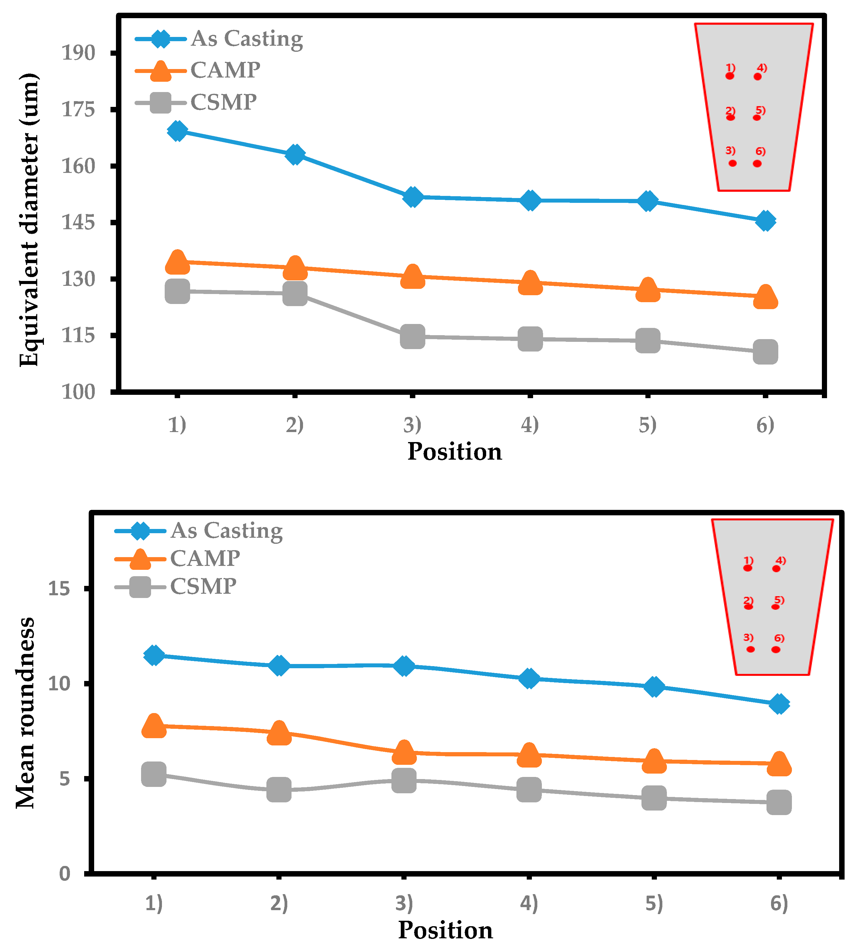
3)
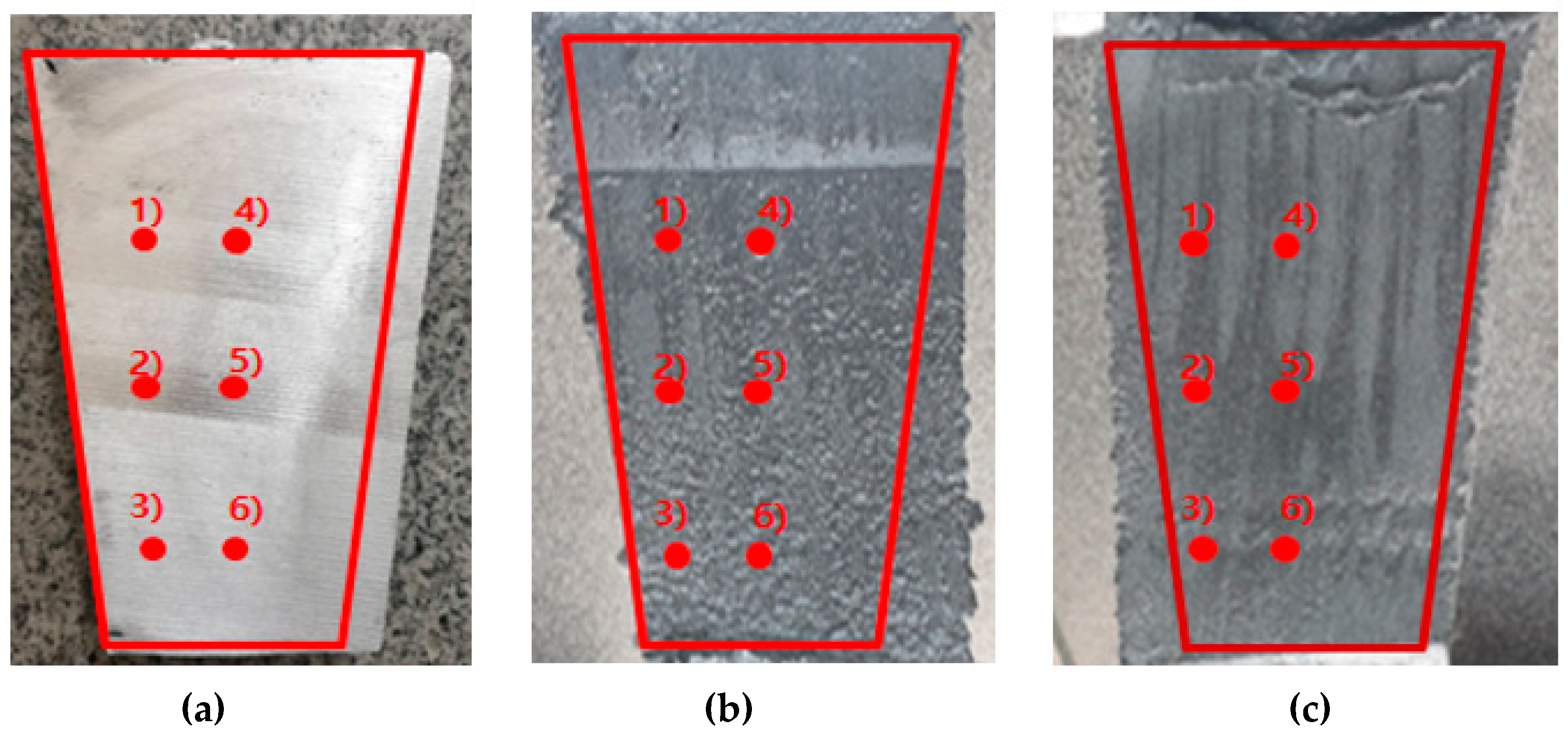
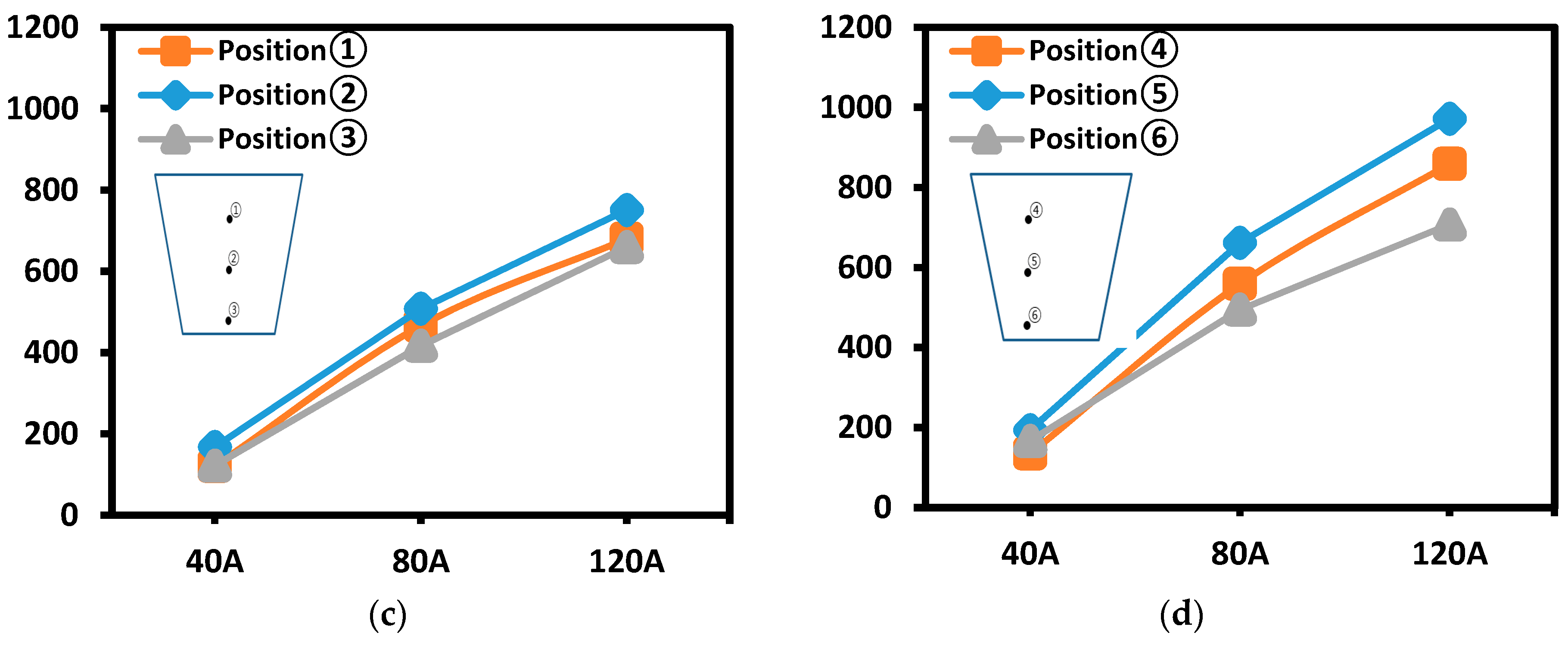
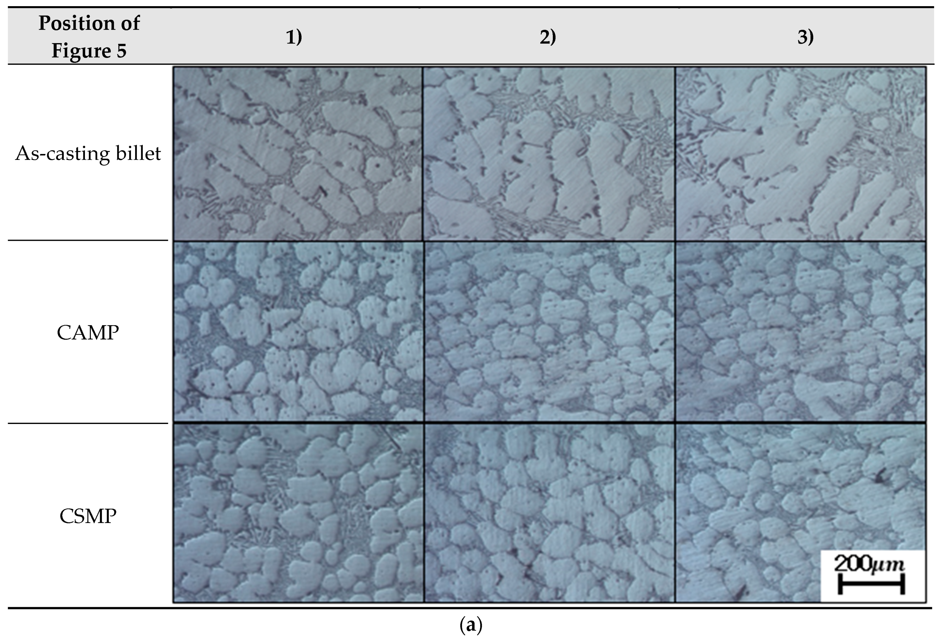
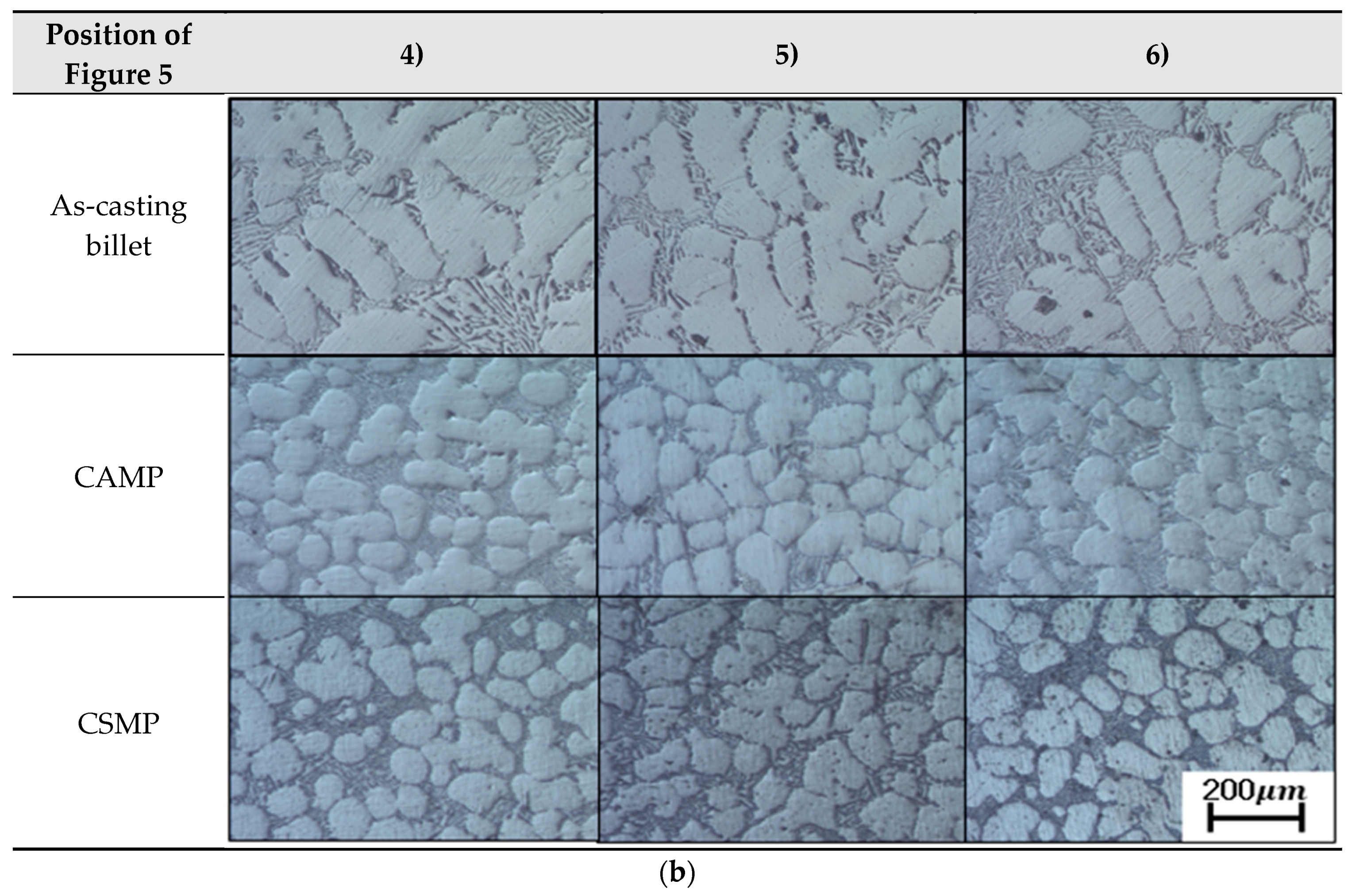
CSMP showed more spherical particles in the slurry than the CAMP, while the microstructure of the edges was somewhat irregular and relatively larger than those in the center of the slurry.
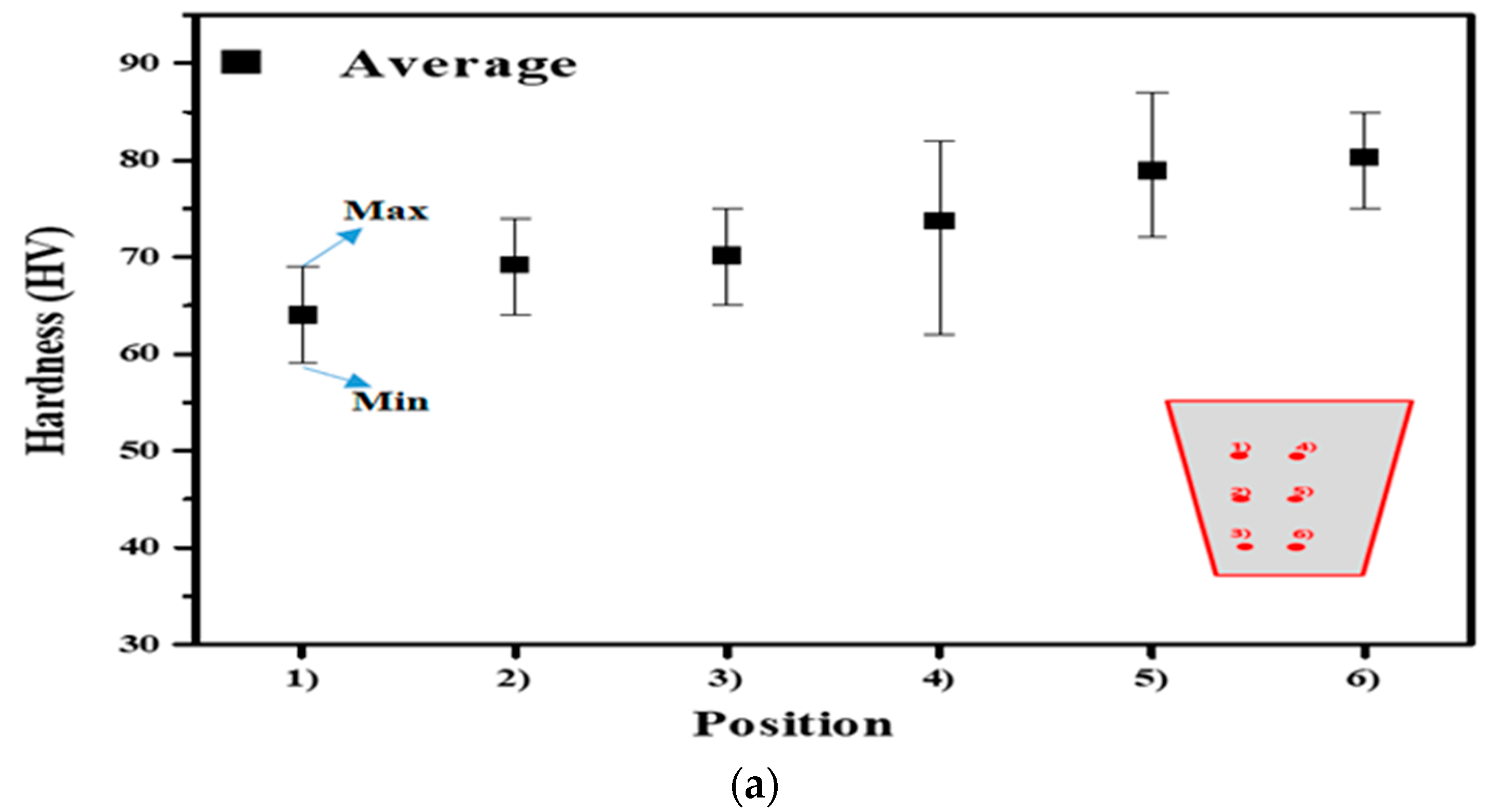
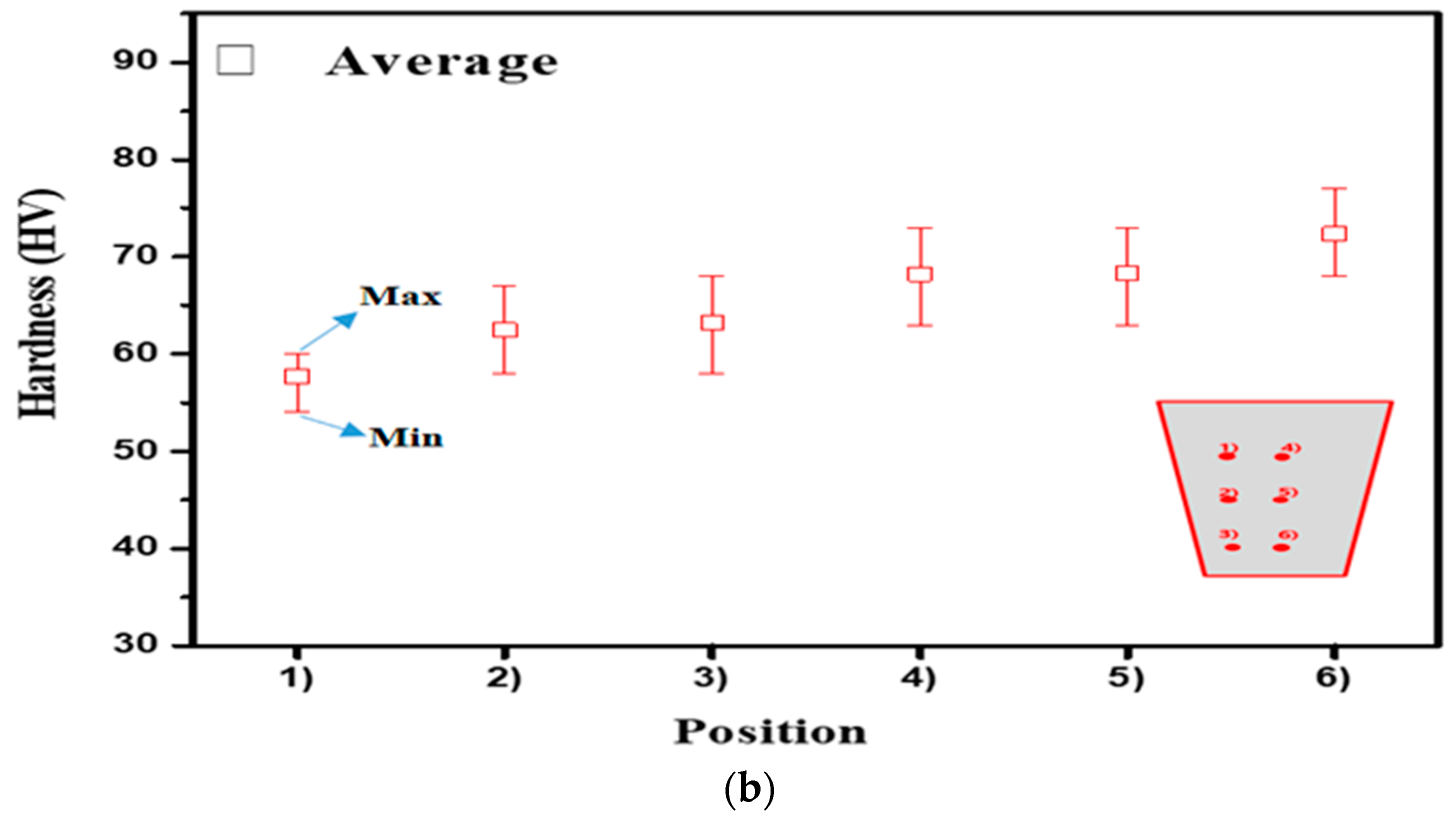
4)
CSMP, which has the best stirring effect, measured 80 HV to 64 HV, and CAMP 72.1 HV to 59.1 HV.

Author Contributions

J.S.R. and M.H. designed the experiment tools and performed the experiment; C.K.J. and J.H.P. analyzed the experimental results, whereas C.G.K. maintained and examined them. All authors contributed to discussions and revisions. All authors have read and agreed to the published version of the manuscript.

Funding

This work was supported by the World Class 300 Project R&D (No. S2640396) of the MOTIE, MSS(Korea). This work was supported by the National Research Foundation of Korea (NRF) grant funded by the Korean government (MSIP) through the GCRC-SOP (No. 2011-0030013).

Conflicts of Interest

The authors declare no conflicts of interest.

References

  1. Park, C.; Kim, S.S.Y.; Kwon, Y.N.; Lee, Y.S.; Lee, J.H. Mechanical and corrosion properties of rheocast and low-pressure cast A356-T6 alloy. Mater. Sci. Eng. A 2005, 391, 86–94. [Google Scholar] [CrossRef]
  2. Tsai, Y.C.; Chou, C.Y.; Lee, S.L.; Lin, C.K.; Lin, J.C.; Lim, S.S. Effect of trace La addition on the microstructures and mechanical properties of A356 (Al–7Si–0.35Mg) aluminum alloys. J. Alloys Compd. 2009, 487, 157–162. [Google Scholar] [CrossRef]
  3. Kim, E.S.; Lee, K.H. Product Design for High Technology of DieCasting. J. Korean Foundrymen Soc. 2004, 24, 251–264. [Google Scholar]
  4. Ebisawa, M. The Latest News of Die Casting Technology. J. Korean Foundrymen Soc. 2004, 2, 71–78. [Google Scholar]
  5. Kang, C.G.; Choi, J.C.; Bae, W.B. Semi-Solid Forming, Casting and Forging Technologies of Lightweight Materials. J. Korean Soc. Precis. Eng. 2000, 7, 7–21. [Google Scholar]
  6. Spencer, D.B.; Mehrabian, R.; Flemings, M.C. Rheological Behavior of Sn-15% Pb in the Crystallization Range. Metall. Mater. Trans. A 1972, 3, 1925–1932. [Google Scholar] [CrossRef]
  7. Ragab, K.A.; Bouazara, M.; Bouaicha, A.; Allooui, O. Microstructural and mechanical features of aluminium semi-solid alloys made by rheocasting technique. J. Mater. Sci. Technol. 2016, 33, 646–655. [Google Scholar] [CrossRef]
  8. Sivabalan, R.; Thangadurai, K.R. Rheocasting of Aluminum Alloy A356 based on Various Parameters: A Review. Int. J. Eng. Res. Technol. 2018, 7, 250–254. [Google Scholar]
  9. Kumar, S.D.; Ghose, J.; Mandal, A. Thixoforming of light-weight alloys and composites: An approach toward sustainable manufacturing. In Sustainable Engineering Products and Manufacturing Technologies; Academic Press: Cambridge, MA, USA, 2019; pp. 25–43. [Google Scholar]
  10. Afandi, Y.; Zulfia, A. Fabrication of Aluminium Matrix Composite Using Thixoforming Process for High Strength Material Components. J. Mater. Sci. Eng. A 2019, 9, 149–152. [Google Scholar]
  11. Pola, A.; Tocci, M.; Kapranos, P. Microstructure and Properties of Semi-Solid Aluminum Alloys: A Literature Review. Metals 2018, 8, 181. [Google Scholar] [CrossRef] [Green Version]
  12. Kapranos, P. Current State of Semi-Solid Net-Shape Die Casting. Metals 2019, 9, 1301. [Google Scholar]
  13. Irani, S.B.; Hanzaki, A.Z.; Bazaz, B.; Roosraei, A.A. Microstructure evolution and semi-solid deformation behavior of an A356 aluminum alloy processed by strain induced melt activated method. Mater. Des. 2013, 46, 579–587. [Google Scholar]
  14. Jaberi, F.S.; Cockcroft, S.L.; Maijer, D.M.; Philion, A.B. Comparison of the semi-solid constitutive behaviour of A356 and B206 aluminum foundry alloys. J. Mater. Process. Technol. 2019, 266, 37–45. [Google Scholar]
  15. Liu, Z.; Mao, W.; Zhao, Z. Research on Semi-Solid Slurry of a Hypoeutectic Al-Si Alloy Prepared by Low Superheat Pouring and Weak Electromagnetic Stirring. Rare Met. 2006, 252, 177–183. [Google Scholar]
  16. Bae, J.W.; Kim, T.W.; Kang, C.G. Experimental investigation for rheology forming process of Al–7% Si aluminum alloy with electromagnetic system. J. Mater. Process. Technol. 2007, 191, 165–169. [Google Scholar]
  17. Jin, C.K.; Jang, C.H.; Kang, C.G. Effect of the process parameters on the formability, microstructure and mechanical properties of thin plates fabricated by rheology forging process with electromagnetic stirring method. Metall. Mater. Trans. B 2014, 45, 193–211. [Google Scholar]
  18. Mingjun, L.; Yuichiro, M.; Isao, M.; Naoki, O.; Shuji, T. Imposition Time Dependent Microstructure Formation in 7150 Aluminum Alloy Solidified by an Electromagnetic Stirring Technique. Mat. Trans. 2018, 59, 1603–1609. [Google Scholar]
  19. An, G.; Junwen, Z.; Chao, X.; Hu, L.; Jing, H.; Xu, Z. Effects of Pouring Temperature and Electromagnetic Stirring on Porosity and Mechanical Properties of A357 Aluminum Alloy Rheo-Diecasting terials. J. Mater. Eng. Perform. 2018, 27, 2373–2380. [Google Scholar]
  20. Qiu, Y.; Zhang, Z.; Luo, Y.; Gao, M.; Li, B.; Chen, C. Effect of coupled annular electromagnetic stirring and intercooling on the microstructures, macrosegregation and properties of large-sized 2219 aluminum alloy billets. Int. J. Mater. Res. 2018, 109, 469–475. [Google Scholar]
  21. Jun, W.Z.; An, G.; Hu, L.; Xu, Z.; Jing, H.; Shu, S.W. Semisolid slurry of 7A04 aluminum alloy prepared by electromagnetic stirring and Sc, Zr additions. China Foundry 2017, 14, 188–193. [Google Scholar]
  22. Luo, Y.; Zhang, Z. Numerical modeling of annular electromagnetic stirring with intercooling in direct chill casting of 7005 aluminum alloy billet. Prog. Nat. Sci. Mater. Int. 2019, 29, 81–87. [Google Scholar] [CrossRef]
  23. Kang, C.G.; Bae, J.W.; Kim, B.M. The grain size control of A356 aluminum alloy by horizontal electromagnetic stirring for rheology forging. J. Mater. Process. Technol. 2007, 187, 344–348. [Google Scholar] [CrossRef]
  24. Zoqui, E.J.; Paes, M.; Sadipi, E.E. Macro- and microstructure analysis of SSM A356 produced by electromagnetic stirring. J. Mater. Process. Technol. 2002, 120, 365–373. [Google Scholar] [CrossRef]
Figure 1. Scheme of electromagnetic stirring.
Metals 10 00460 g001
Figure 2. Crucibles cup shape and measurement position of electromagnets.
Metals 10 00460 g002
Figure 3. Change in solid fraction with temperature of A356.
Metals 10 00460 g003
Figure 4. Scheme magnetic current input method: (a) adjacent pole counterclockwise (CAMP); (b) counterclockwise of symmetry magnetic pole (CSMP).
Metals 10 00460 g004
Figure 5. Photographs of A356 sample and the position of the microstructure measurement point: (a) As-cast billet (b) CSMP of Table 2; (c) CAMP of Table 2.
Metals 10 00460 g005
Figure 6. Magnetic induction density of according to magnetic impression method: (a) Measurement point; of center to CAMP; (b) measurement point of surface to CAMP; (c) measurement point of center to CSMP; (d) measurement point of surface to CSMP.
Metals 10 00460 g006aMetals 10 00460 g006b
Figure 7. Microstructure of A356 100×: (a) measurement point of center; (b) measurement point of surface.
Metals 10 00460 g007aMetals 10 00460 g007b
Figure 8. Equivalent diameter and roundness by A356 alloy.
Metals 10 00460 g008
Figure 9. Vickers hardness of A356 semi-solid slurry at different positions: (a) CMSP; (b) CAMP.
Metals 10 00460 g009aMetals 10 00460 g009b
Table 1. 6 polarity electromagnetic system.
Inside diameter145 mm
Outside diameter600 mm
Height260 mm
Table 2. Chemical composition of A356 ally (wt %).
CuSiFeMgMnZnNi
0.0086.650.080.350.0080.020.01
TiSnPbCrCaSrAl
0.120.0070.0160.0010.00080.022Bal
Table 3. Magnetic current input method.
Current Input Method NumberCurrent Input MethodCurrent Input ProcedurePolarity
(1)Counterclockwise of adjacent magnetic pole (CAMP)ⓐⓑ→ⓒⓓ→ⓔⓕ(+) polarity:
ⓐ,ⓒ,ⓔ
(−) polarity:
ⓑ,ⓓ,ⓕ
(2)Counterclockwise of symmetry magnetic pole (CSMP)ⓐⓓ→ⓑⓔ→ⓒⓕ(+) polarity:
ⓐ,ⓑ,ⓒ
(−) polarity:
ⓓ,ⓔ,ⓕ
Table 4. Experimental conditions of electromagnetic stirring with A356 alloy.
Stirring Current,
A
Electromagnetic Force,
Gauss
Stirring Temperature,
°C
Pouring Temperature,
°C
As-casting 700
CSMP, CAMP120665, 972585700
Table 5. Optical microscope BX53M model.
Eyepiece
(X)
Objectives
(X)
Halogen LampStage
1050, 100,
200, 500, 1000
12V 100WX-Y

