Article

High-Speed Rotary Ultrasonic Elliptical Milling of Ti-6Al-4V Using High-Pressure Coolant

1
School of Mechanical Engineering and Automation, Beihang University, Beijing 100191, China
2
Shenyuan Honors College, Beihang University, Beijing 100191, China
3
Beijing Advanced Innovation Center for Biomedical Engineering, Beihang University, Beijing 100191, China
4
Institute of Bionic and Micro-Nano Systems, Beihang University, Beijing 100191, China
5
Inner Mongolia Metal Material Research Institute, Ningbo 315103, China
6
Beijing Spacecrafts, China Academy of Space Technology, Beijing 100094, China
7
Department of Mechanical Engineering, North University of China, Taiyuan 038507, China
*
Author to whom correspondence should be addressed.
Metals 2020, 10(4), 500; https://doi.org/10.3390/met10040500
Submission received: 28 February 2020 / Revised: 30 March 2020 / Accepted: 1 April 2020 / Published: 10 April 2020

Abstract

:
High-speed rotary ultrasonic elliptical milling (HRUEM), as a novel ultrasonic vibration cutting method, has been introduced in milling the alloy Ti-6Al-4V. The application of ultrasonic vibration in high-speed milling can help open the cutting contact area intermittently. New cutting effects will happen with full use of the separation effect brought by ultrasonic vibration and the cooling effect brought by a high-pressure coolant (HPC). On the basis of that, this paper firstly introduces HPC into HRUEM of Ti-6Al-4V in the open literature and analyzes the tool-workpiece separation cooling mechanism in HRUEM, including kinematic analysis of tool tip trajectories, tool-workpiece separation principles and high-pressure coolant effects. We have conducted a comprehensive experimental study and the results show when HPC is increased to 200 bar, compared to conventional milling (CM), the tool life in HUREM can be extended by 6.6 times at 80 m/min, 4.2 times at 120 m/min and 2.4 times at 160 m/min. The maximum material removal volume (MRV) for a given new end mill in HRUEM is increased by 657% approximately. When the cutting speed is 80 m/min, the cutting temperature of the workpiece in HRUEM is reduced by 24.1% compared to that of CM. By applying the combination of HPC and tool-workpiece periodic separation, we can significantly enhance the cooling and lubrication efficiency in HRUEM and also inhibit the tool wear mode of adhesive wear typically occurred in CM.

Graphical Abstract

1. Introduction

Titanium alloys have been widely applied in aerospace industries due to their high strength-to-weight ratio and excellent corrosion resistance [1,2]. With the increasing demand for various low-stiffness aero-structural titanium alloys, milling of those titanium alloys with high efficiency and good surface quality has become a key issue [3,4]. As an effective method to meet those two demands, high-speed milling has been extensively applied in a variety of materials machining [5]. However, high-speed milling of the titanium alloys is still a challenge owing to its low thermal conductivity, high chemical reactivity and other constraining factors [6].
Venugopa et al. [7] reported that a narrow region adjacent to the cutting edge would be formed when machining the titanium alloy at a high cutting speed. The temperature of this region could be as high as 1000 °C. Li et al. [8] presented a detailed analysis of tool failure progression through an experimental study on high speed milling (HSM) of Ti-6Al-4V alloy, pointing out that thermal damage was the main tool wear mechanism at a high cutting speed. Therefore, we could reach the conclusion that cutting performance in the high-speed milling of titanium alloys directly depends on the effectiveness of provided cooling/lubrication. Vishal S. Sharma et al. [9] presented an overview of major advances in cooling/lubrication techniques for high-speed machining, such as minimum quantity lubrication/near dry machining, high-pressure coolant (HPC), cryogenic cooling, compressed air cooling and the use of solid lubricants/coolants. These techniques can result in a reduction in friction and heat at the cutting zone, and improve the cutting performance in the high-speed milling process [10,11,12,13,14].
Kovacevic et al. [15] tested HPC by milling titanium alloy and found that the surface obtained with the use of HPC is much better than the one by flood cooling. The welding problems of hot chips and cutting edges that are commonly encountered in titanium machining have been solved by applying HPC, thereby leading to enhanced surface quality and prolonged tool life. Bermingham et al. [16] milled the titanium components with HPC and reported the cutting speed could be increased by 20% using HPC without sacrificing tool life. The application of HPC suppressed the rate of tool wear and allowed higher material removal rates. Nevertheless, EDS analysis by Diniz and Micaroni [17] showed that no coolant element was detected in the crater wear area and flank wear area when cutting under HPC indicating that the areas close to the cutting edge are so tightly coupled that even high pressure fluids found it difficult to penetrate the tool-workpiece contact area. We could reach the conclusion that the potential cooling effect of HPC in high-speed milling is limited in the tool-workpiece contact area.
As an intermittent cutting method, ultrasonic vibration machining (UAM) has been widely discussed for its ability to open the tool-workpiece contact area intermittently. As one of the typical UAM processes, the ultrasonic-assisted milling technique has been widely applied to machine difficult-to-cut alloys for its superiority in expanding tool life, lowering cutting force and delivering better surface quality [18,19,20,21,22,23,24]. In order to obtain the intermittent cutting mode between the tool and the workpiece in UAM, its relative velocity in cutting direction should be controlled as the opposite to the tool rotation direction periodically. The above machining advantages brought by ultrasonic vibration usually occur at a lower range of cutting speed (usually v < 20 m/min) and gradually weaken and eventually disappear as the cutting speed increases. Hence, UAM is usually considered not suitable for high speed machining [25]. Recently, Liu et al. [26] proposed a novel high-speed rotary ultrasonic elliptical milling (HRUEM) method for high-speed ( v = 160   m / min ) side milling of Ti-6Al-4V alloy with the ultrasonic vibration vertical to the direction of cutting speed. Ultrasonic elliptical vibration in a flat surface perpendicular to a tool axis was imposed on a rotating tool, and an intermittent cutting mode between the tool and the workpiece can be achieved at high cutting speeds due to the overlapping of trajectories for the adjacent cutting tool tips [27,28]. Due to HRUEM’s cutting characteristics (reduced cutting temperature and increased lubrication) at high cutting speeds, the penetration of cooling fluid into the cutting area can be effectively enhanced, significantly improving cutting performance. The preliminary results of high-speed machining of Ti-6Al-4V by HRUEM showed that ultrasonic elliptical vibration in HRUEM could improve compressive residual stress, plastic deformation and work-hardening of the processed surfaces [29,30].
Therefore, we believe combining the separation effect brought by ultrasonic vibration and the cooling effect brought by HPC may bring new ideas to high-speed milling. This paper firstly introduces HPC into the HRUEM process with the purpose of investigating the cutting performance in HRUEM of titanium alloy with HPC, including tool life, material removal volume (MRV) and cutting temperature. The principle of tool-workpiece separation cooling in HRUEM and tool wear mechanism is also theoretically analyzed in the paper.

2. Principle of Tool-Workpiece Separation Cooling Effect in HRUEM

2.1. Kinematic Analysis of Tool Tip Trajectories in HRUEM

The HRUEM could be considered as a hybrid cutting process with several independent motions, including tool’s rotary motion, table’s feed motion and imposed ultrasonic elliptical vibration. An illustration of the HRUEM process with a four-flute end mill is presented in Figure 1.
The trajectories of the tool tips in the conventional milling (CM) process are composed of the feed motion of the table and the rotary motion of the tool. The Tool-Cartesian coordinate system is shown in Figure 1. The trajectories of tooltips in CM can be expressed as:
{ x = v f z t + D 2 cos ( ω r t 2 π ( i 1 ) N ) y = D 2 sin ( ω r t 2 π ( i 1 ) N ) z = 0
where x , y and z represent motion displacement of tool-tips in the Tool-Cartesian coordinate system, v f z is the workpiece feed speed, t is the instantaneous cutting time, D is the diameter of the end-mill, ω r is the angular velocity of milling machine spindle, N is the number of flutes, and i ( i = 1,2 … N ) is the sequence number of the selected tool tip.
The reason why HRUEM is different from CM is that ultrasonic elliptical vibration of the tool in the O X Y plane is added to the trajectory of the tool tip. So far the following assumptions have been made: First, the initial minor axis of the ellipse with amplitude A coincides with the Y direction, and that the major axis of the ellipse with amplitude B coincides with the X direction. Second, the initial position ellipse is located in the largest negative direction of the X axis. Third, the ellipse vibrates clockwise. Therefore we believe the displacement function of ultrasonic elliptical vibration can be expressed as:
{ x v = A cos ( 2 π f t 2 π i N ) cos α B sin ( 2 π f t 2 π i N ) sin α y v = A cos ( 2 π f t 2 π i N ) sin α + B sin ( 2 π f t 2 π i N ) cos α
where f is ultrasonic vibration frequency, and α is the rotation angle of the end mill.
According to fundamental Equations (1) and (2), the trajectories of tool tips in the HRUEM process can be expressed as:
{ x H = v f z t + D 2 cos ( ω r t 2 π ( i 1 ) N ) + A cos ( 2 π f t 2 π i N ) cos α B sin ( 2 π f t 2 π i N ) sin α y H = D 2 sin ( ω r t 2 π ( i 1 ) N ) + A cos ( 2 π f t 2 π i N ) sin α + B sin ( 2 π f t 2 π i N ) cos α z H = 0
According to Equation (3), the tool-tip motion trajectories in the HRUEM method are obtained by using MATLAB software, as shown in Figure 2. In a partially enlarged view, the trajectory of the tool tip in HRUEM is wavy instead of a standing arc in CM. Moreover, the adjacent tool tip trajectories intersect, which provides conditions for separated cutting. The specific principle of tool-workpiece separation will be derived in the next section.

2.2. The Principle of Tool-Workpiece Separation in HRUEM

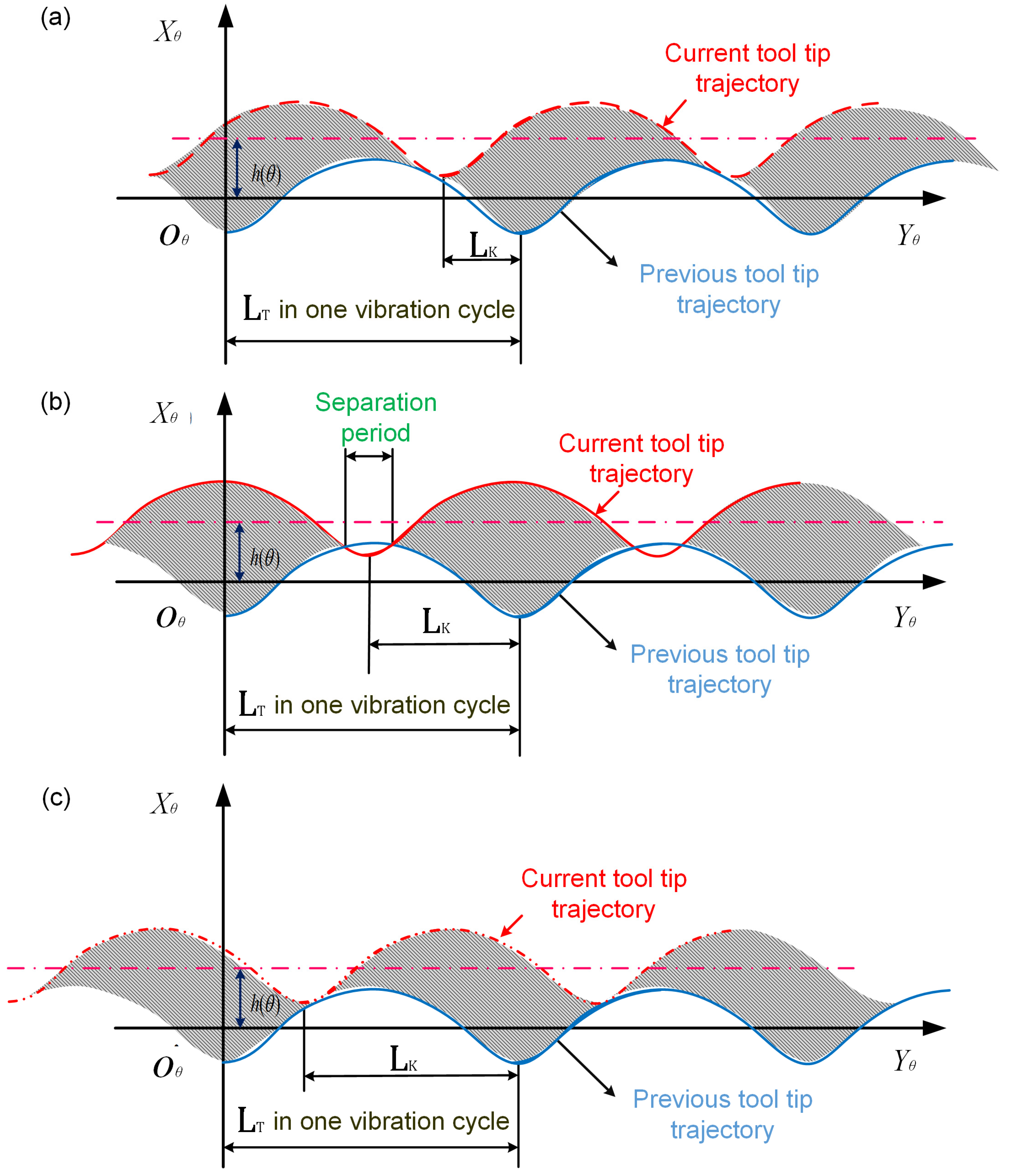
The separate material removal process of HRUEM depends on the interaction of multiple cutting trajectories of the end mill. The relative relationship between tool-tip trajectories is determined by matching cutting parameters (cutting speed, feed rate per tooth and radial cutting depth) and vibration parameters (frequency and amplitude). Hence, the intersection of adjacent cutting trajectories is a necessary condition to achieve the intermittent cutting mode in HRUEM. A new coordinate system, O θ X θ , Y θ , was set up corresponding to the tool rotation angle θ , as shown in Figure 3. The Y θ -axis coincides with the tool tip cutting speed direction of CM, the X θ -axis is perpendicular to the Y θ -axis, and O θ is at the cutting trajectory balanced position of the previous tool tip.
In CM, the chip thickness can be defined as a function of rotation angle of the end mill θ as:
h ( θ ) = f z cos θ
where f z is the feed rate per tooth of the end mill. When ultrasonic elliptical vibration is applied, h ( θ ) can be regarded as the distance between the vibration balanced positions of adjacent tool tip trajectories corresponding to rotation angle θ .
The difference in displacement caused by the vibration delay between the rear tool tip and previous tool tip can be expressed as:
L K = K L T
where L T is the distance generated by the tool tip during one vibration cycle, K is the vibration period delay coefficient between the current tool tip trajectory and previous tool tip trajectory [26].
L T = v / f
where v is the nominal cutting speed of the tool tip in CM.
The motion of the previous tool tip relative to the coordinate system O θ X θ , Y θ can be expressed as:
{ x 1 = A cos ( 2 π f t 1 π ) y 1 = v t 1 + B sin ( 2 π f t 1 π )
The motion of the current consecutive tool tip relative to the coordinate system O θ X θ , Y θ can be expressed as:
{ x 2 = A cos ( 2 π f t 2 π ) + f z cos θ y 2 = v ( t 2 K f ) + B sin ( 2 π f t 2 π ) , θ ( 0 , π 2 ) , t 2 ( 0 , 1 f )
The analysis shows that to realize separate-type cutting throughout the entire rotary ultrasonic elliptical milling process, two adjacent cutting curves must intersect at the entry position of down milling, meaning real solutions can be obtained from the following equations:
{ θ = arcsin r a e r x 1 ( t 1 ) = x 2 ( t 2 ) y 1 ( t 1 ) = y 2 ( t 2 ) x 1 y 1 | t 1 = x 2 y 2 | t 2 , t 1 , t 2 ( 0 , 1 f )
Substituting Equations (4)–(8) into Equation (9), the separation criteria of tool and workpiece in HRUEM can be defined as:
{ θ = arcsin r a e r f z cos θ 2 A 1 π arcsin f z cos θ 2 A K 1 1 π arcsin f z cos θ 2 A
Obviously, only when the cutting and vibration parameters meet the above conditions can separate cutting be realized in the HRUEM process.

2.3. Analysis of High-Pressure Coolant in HRUEM

In CM, different tool flutes can have an interrupted cutting characteristic in which periodic separation of tool and workpiece will be achieved. Moreover, if Equation (10) is satisfied, HRUEM can also add periodic ultrasonic frequency separation between the end mill and the workpiece due to ultrasonic elliptical vibration.
The tool in HRUEM has different working conditions on cutting duration and non-cutting duration. Therefore, when HPC is applied in HRUEM, the cutting contact area will have different cooling conditions under two working durations.
When in the cutting duration, the cooling conditions are similar to those in the CM process. When an HPC jet is applied to the flank, high-pressure fluid can penetrate the workpiece-tool interface [31], providing better cooling and lubrication of the tool. In addition, it can also work as cushions to reduce friction between tool flank and the machined surface of workpiece. During high-speed milling, the largest heat source is often located near the cutting edge while the chips and the workpiece tightly contact the rake face of the tool respectively, as shown in the cutting duration in Figure 4. Since the coolant can’t reach the cutting edge, the cutting heat will quickly accumulate and generate a high cutting temperature. This is the main reason why CM method still suffers from rapid tool wear even under HPC technique.
When the tool is in the non-cutting duration in HRUEM, the cutting edge will separate from the workpiece. In this case, a microchannel is formed between the tool and the workpiece, as shown in Figure 4. If the coolant is used under that circumstance, only a small amount of it can penetrate into this microchannel to reach the cutting edge, so the cooling capacity is still limited. During high-speed milling, the limited amount of coolant penetrated in the cutting contact area can not carry a large amount of rapidly accumulated cutting heat in time. However, if HPC is applied, the coolant can quickly rush through the microchannel and quickly remove a large amount of cutting heat. we can come to the conclusion that compared to CM, HRUEM with HPC enjoys a better high-speed milling cooling capacity.
Heat dissipation is the key to extend tool life. The heat within a tool is transferred through heat conduction (Qcond) and convection of the coolant on the flank can remove most of it. Although the combined effect of air and radiation convection works for partial heat dissipation, air convection and radiation under HPC conditions can be neglected in HRUEM since heat dissipation is mainly the heat convection (Qconv) transferred from the HPC jet [32].
HPC’s cooling effect during milling process depends on the cutting heat dissipation efficiency of coolant [33], which can be described as:
q = h A ( T s T f )
where q is the heat flux density, h is the convective heat transfer coefficient, A is the contact area, T s is the temperature on the workpiece surface and T f is the coolant’s temperature. We could assume that the temperature difference ( T s T f ) between the workpiece and the coolant is constant, coolant’s cooling effect can be improved by changing the convective heat transfer coefficient h and the workpiece fluid contact area A .
The heat transfer with conventional pouring coolant is mainly based on the natural heat convection process, while the cooling with HPC is mainly based on forced heat convection process. Convective heat transfer coefficient h for the forced heat convection process is related to the Nusselt number N u .
h = λ d N u
where λ is the thermal conductivity of coolant and d is the geometry size of heat conductor. The Nusselt number N u is the ratio of convective to conductive heat transfer across (normal to) the boundary, which will be further determined by Prandtl number P r [32] and Reynolds number R e and other relevant parameters as:
R e = ρ D 2 μ V f
N u = 0.20 R e P r 0.33
V c = C d n π D 2 4 2 P ρ
where V c is the coolant velocity, C d is the nozzle efficiency, n is the nozzle quantity, D is the nozzle diameter and P is the fluid pressure (MPaand ρ is fluid density).
From Equations (13) to (15), Reynolds number R e will increase when fluid pressure goes up eventually leading to the increase of the convective heat transfer coefficient h and heat flux density q . As the pressure of the cutting fluid rises, the convection cooling process will take away a bigger percentage of the cutting heat than the conduction cooling process. Therefore, when HPC is applied in a high-speed milling process, a better heat transfer effect can be reached with more heat taken away.
Figure 5a shows that HPC in CM can not only improve the convective heat transfer coefficient h between the tool and the coolant, but also reach the edge of the contact area between the tool and the workpiece. However, it is difficult for the coolant to reach the cutting contact area and the cooling effect is still limited. As HPC is applied in HRUEM in the non-cutting duration, as shown in Figure 5b, plenty of high-speed coolant can flow through the cutting zone, enabling high-efficiency heat convection to occur between the tool and coolant. Due to the chip breaking characteristics of HRUEM, the chips are smaller and the heat is more easily taken away [26]. We could reach the conclusion that the tool in HRUEM with HPC has the higher tool heat dissipation ability and better cutting temperature reduction effect compared to CM with HPC.

3. Material and Experimental Procedures

3.1. Workpiece Material

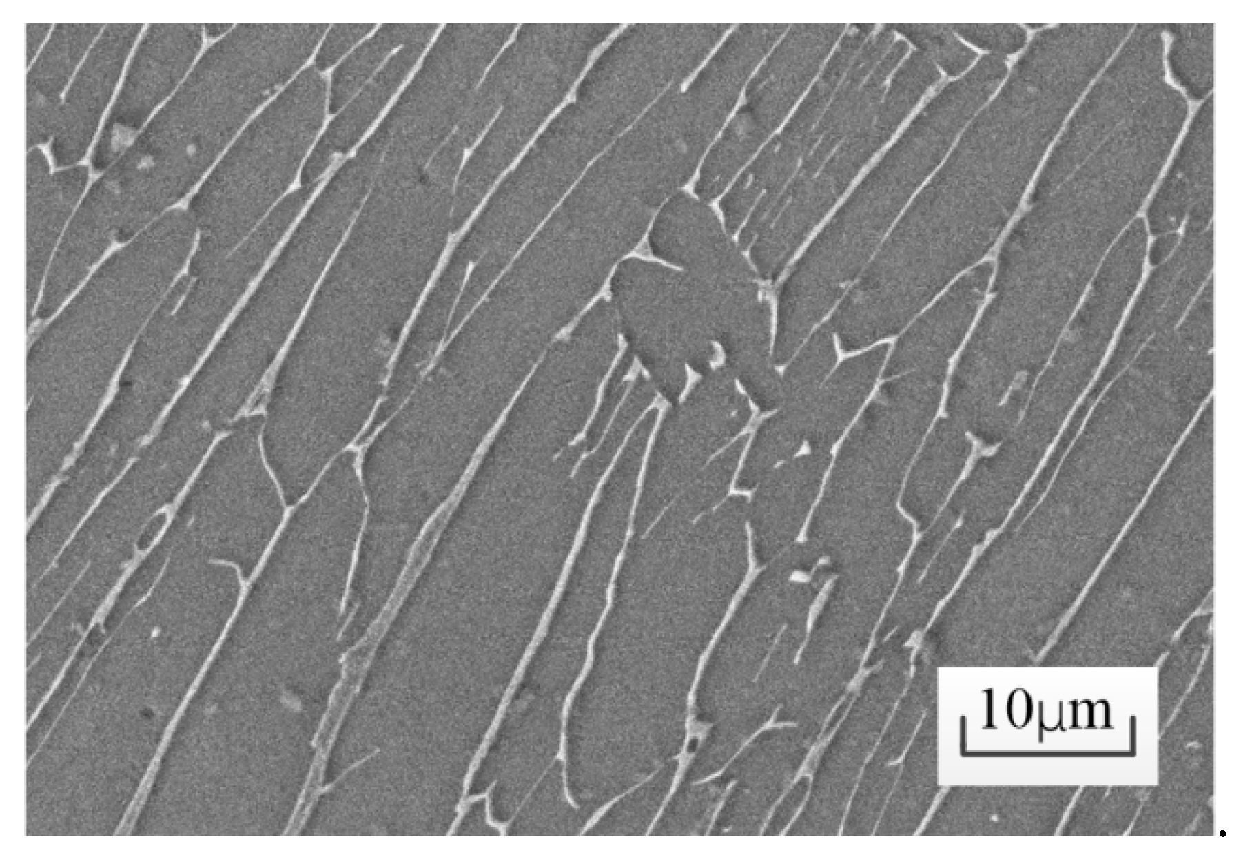
The workpiece material used in experiments was the Ti-6Al-4V alloy. To make sure the experimental results are reliable, samples were produced with the same batch of material in case of metallurgical changes. The microstructure is shown in Figure 6. The physical and mechanical properties are given in Table 1.

3.2. Machining Setup

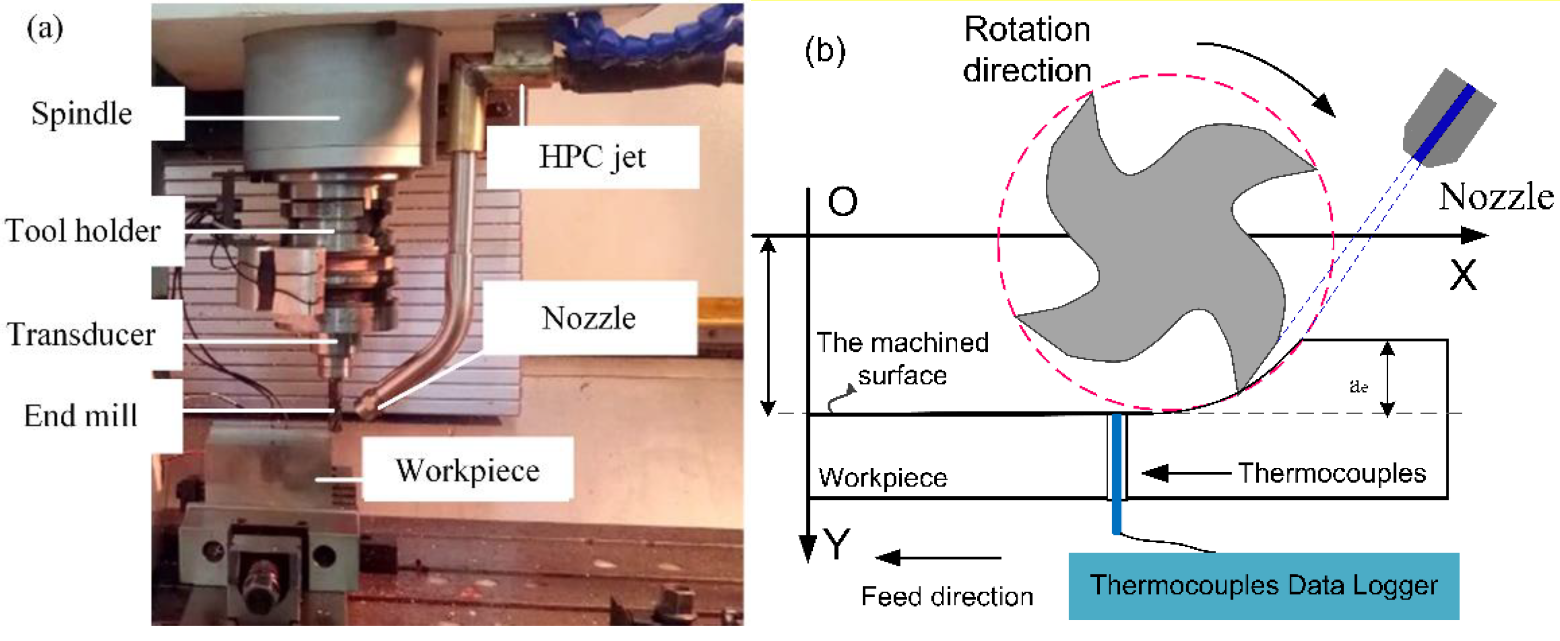
Our self-designed ultrasonic elliptical vibration BT50 end mill holder was composed of a tool holder, an elliptical piezoelectric transducer and a carbide end mill, as shown in Figure 7a. The ultrasonic elliptical vibration in the plane perpendicular to the tool axis was produced at the end of the carbide end mill by the synthesis of a two-dimensional vibration with an approximate 90° phase shift. A four-flute cemented carbide end mill (Zhongneng cemented carbide cutting tools Co., Ltd.) with a diameter of 12 mm was specially designed to improve the vibration transmission of the tool and mounted into the end of the transducer. The vibration amplitudes can be amplified by a stepped horn and maximized at the tool tips. Specifications of the end mill are given in Table 2. To reduce the influence of the tool cutter run-out, we selected the end mills for experiments with a rotary precision within 5 µm. The self-designed ultrasonic power supply converts 220 V, 50 Hz power to a higher frequency AC output, which is sent to the elliptical piezoelectric transducer. The conversion of HRUEM to CM is achieved by switching off the power supply.
All end milling experiments were carried out with HPC on a four-axis CNC milling machine (BV100, Beijing Mechatronics Machine Tool Co., Ltd.) with a maximum spindle speed of 8000 rpm, as shown in Figure 7. Cutting speed hinders the improvement of cutting efficiency. Therefore we selected three cutting speeds for experiments and kept the feed rate per tooth, the axial depth and radial depth constant. Detailed experimental conditions are listed in Table 3. The HPC flow rate is 21 L/min and the nozzle is located approximately 20 mm from the tool tip, as shown in Figure 7a. The angle of the nozzle is carefully adjusted so that the high-pleasure coolant is injected into the cutting area, as shown in Figure 7b. To ensure the accuracy of experiments, each parameter was conducted three times, and the average result was taken as the final value.

3.3. Testing Method

Tool wear experiments were carried on a block workpiece. The images of the tool flank face were captured online with a digital microscope (AM7915MZT, Dino-Lite) to observe tool wear after a certain cutting duration. To evaluate the cutting heat in the Ti-6Al-4V alloy during milling, the thermocouples embedded in the Ti-6Al-4V alloy were used to record temperatures. The K-type thermocouples with a measuring terminal 1 mm in diameter and 5 mm in length were utilized to make sure the working temperature ranged from −200 to +1300 °C. Data acquired by the thermocouples were recorded by the thermocouples data logger, then transmitted to a laptop and analyzed by the data management software afterwards. We drilled a small hole with the diameter of 1.1 mm to embed the thermocouples before the experiments. The positions of the thermocouples were accurately arranged, as shown in Figure 7b. New tools were used for measuring each cutting temperature when different cutting parameters and cooling conditions were applied. To ensure the accurate measurement results, the cutting temperature of each parameter was measured three times, and the average result was taken as the final cutting temperature value. The scanning electron microscope (SEM, Nippon Electronics Corporation, JSM7500, Japan) was used to observe the surface microstructure and micrographs of tool flank faces under various cutting conditions.

4. Results and Discussion

4.1. Tool Life

The rejection or failure of a tool was determined according to ISO standard 8688-2 (1989) and the requirements of finishing milling quality are as follows:
(1)
Average flank wear VB = 0.2 mm,
(2)
Maximum flank wear VBmax = 0.3 mm,
(3)
Excessive chipping/flaking or catastrophic fracture of the cutting edge.
If any of the above criteria were reached, the experiment would be terminated.
The progression of tool flank wear with respect to cutting time under different coolant pressures and cutting speeds in HRUEM and CM is presented in Figure 8. We could see that HRUEM and CM were quite different at different tool wear rates of 200 bar and 50 bar HPC. There is no obvious difference between when the tool wear rate was at 200 bar and 50 bar in CM. In contrast, a distinct difference was detected under same conditions in HRUEM due to the achieved intermittent cutting mode in HRUEM. However, when the cutting speed increased, the tool wear suppression effect by ultrasonic vibration in HRUEM also gradually decreased. However, it is still obviously better than that in CM. For instance, at the 200 bar HPC, the tool wear rate in HRUEM at the cutting speed of 160 m/min was lower than that in CM at the cutting speed of 80 m/min.
Moreover, we found that for a given cutting speed, the tool life in HRUEM with 200 bar HPC was the longest under all four conditions. It reached a maximum of 28 h at the cutting speed of 80 m/min in HRUEM with 200 bar HPC. When HPC is applied, the changes of flank wear progressions for the two methods turned out to be quite different from each other. At the cutting speed of 80 m/min and 50 bar HPC, the tool life ratio of HRUEM to CM was about 5.5. When the coolant pressure increased to 200 bar, the tool life ratio would be further expanded to 6.9. Similar trends were observed at high cutting speeds (120 m/min and 160 m/min). For instance, the tool life ratio of HRUEM to CM at 120 m/min and 200 bar was about 5.2 and went down to about 3.4 at 160 m/min and 200 bar. It could be found that the expanding effect on tool life by ultrasonic vibration will be weakened with the cutting speed increases. This is because the ratio of the vibration frequency f to spindle speed n decreased as cutting speeds went up. It means that the tool-workpiece contact ratio (TWCR) escalates as cutting speeds increase and the engagement time between the tool and the workpiece in single vibration cycle lasts longer at higher cutting speeds [19]. The excellent cooling and lubrication effects brought by separation characteristic in HRUEM will be weakened at a higher value of TWCR and more heat accumulates in the cutting zone. As a result, the deteriorating cutting condition accelerates the tool flank wear at high cutting speeds.

4.2. Material Removal Volume

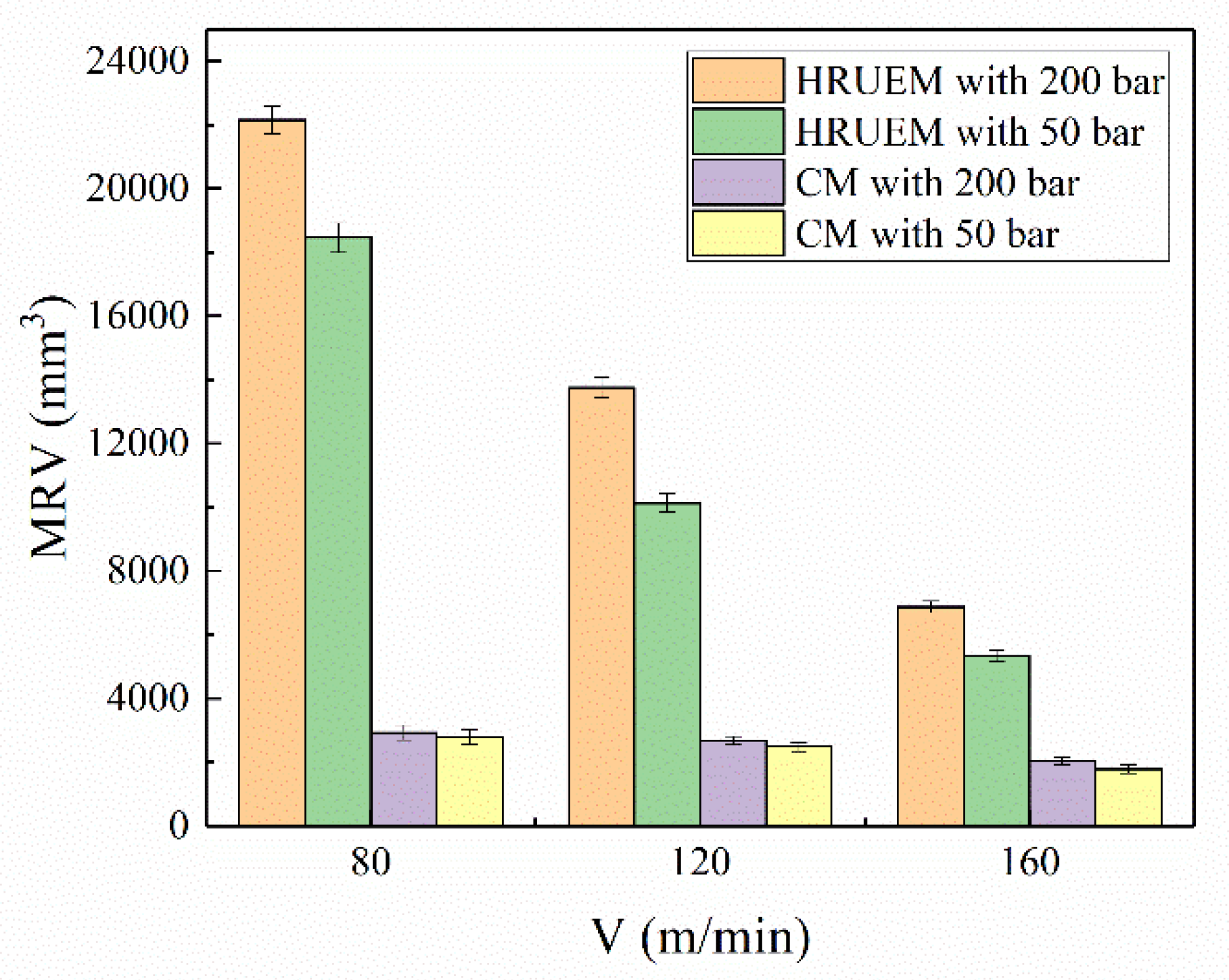
Figure 9 shows MRV before the tool failure under different coolant pressures and cutting speeds in both HRUEM and CM. Results show that HRUEM with HPC exhibits good performance in MRV compared to CM. In industrial production, the milling speed of titanium alloys normally will not exceed 80 m/min considering tool life constrains and MRV. At a cutting speed of 80 m/min, the MRV of CM with 50 bar was 2801 mm3. When the pressure went up to 200 bar, the MRV was 2928 mm3. The HRUEM with 50 bar increased significantly, resulting in a higher MRV of 18,461 mm3. The highest MRV was obtained by HRUEM with 200 bar under all four conditions at the same cutting speed: 22,154 mm3 at a cutting speed of 80 m/min, 13751 mm3 at a speed of 120 m/min and 6875 mm3 at a speed of 160 m/min, respectively. Compared to CM with 200 bar at the cutting speed of 80 m/min, the maximum MRV for a given new end mill in HRUEM with 200 bar is increased by about 657%. The combination of HRUEM and HPC can significantly improve the machining productivity. For instance, compared with CM at the cutting speed of 80 m/min and 200 bar HPC, the MRV in HRUEM at the cutting speed of 160 m/min and 200 bar HPC was increased by about 135%. Moreover, the doubled cutting speed achieved in HRUEM indicates the material removal rate (MRR) was twice of that in CM. Therefore, HRUEM with HPC is an effective method for milling of titanium alloys with high efficiency. In addition, cutting speed had a more significant influence on the surface roughness in HRUEM compared with CM. the surface roughness (Ra) value of HRUEM decreases with increasing cutting speed, until it approaches the value of CM at the same cutting speed [29].

4.3. The Average Integral Temperature over the Tool-Chip Interface

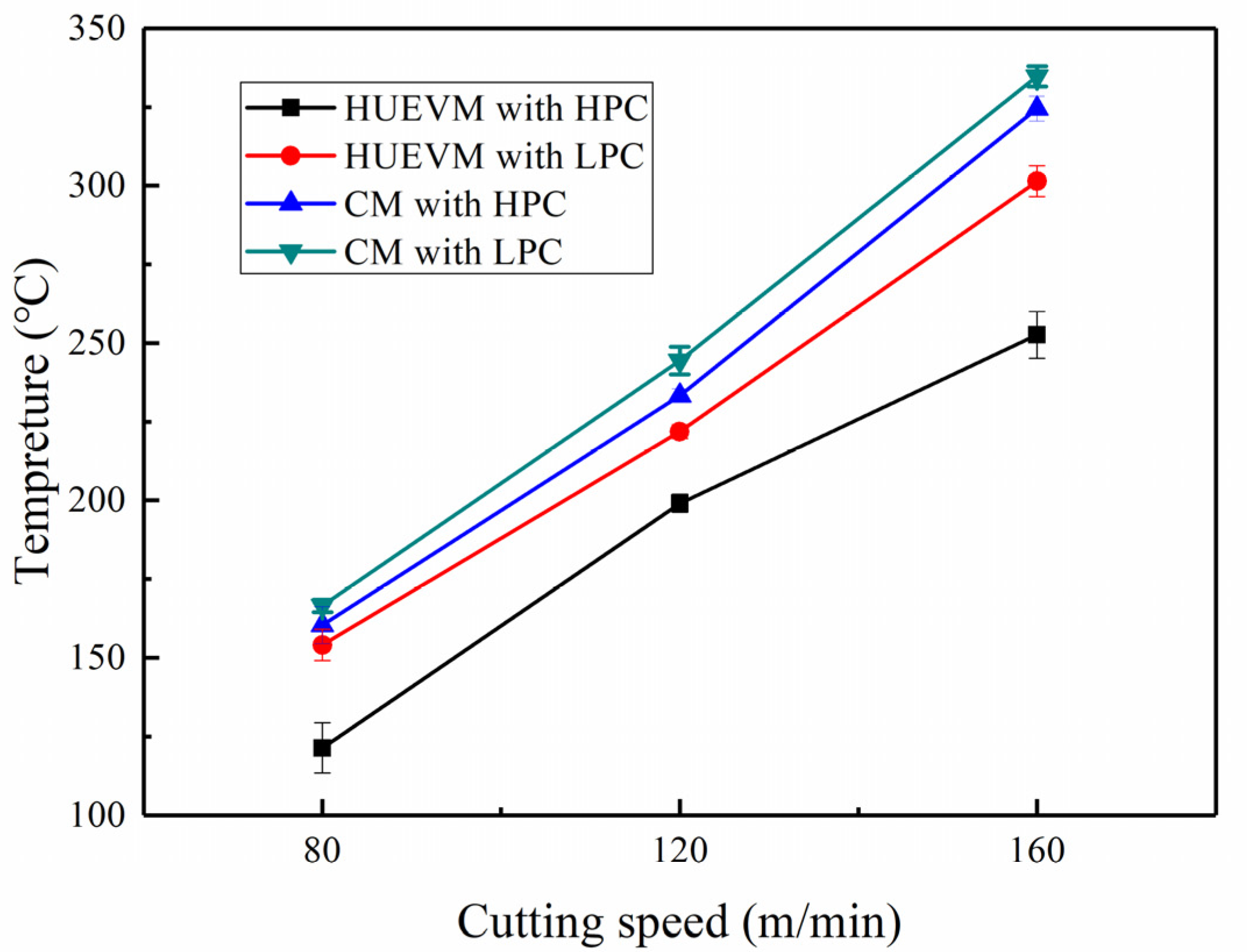
The average integral temperature over the tool-chip interface of both CM and HRUEM at different coolant pressures and cutting speeds are shown in Figure 10. Due to the difficulty in measuring cutting temperature in practice, the change trend of this temperature can represent the change of cutting temperature to some extent. We could see that the temperature rose as the cutting speed increased under all coolant pressures for both cutting methods. In CM, the highest temperature occurred at the cutting speed of 160 m/min and 50 bar HPC with the value of 334.8 °C. When 200 bar was applied to CM, the temperature was reduced to 324.5 °C. Compared with CM, when HPC was applied to HRUEM, the temperature was significantly reduced, i.e., 301.4 °C at 50 bar and 252.6 °C at 200 bar. Compared to CM with 50 bar, the reduction rate of the temperature for CM with 200 bar was about 3.8% at 80 m/min, 4.8% at 120 m/min and 3.2% at 160 m/min respectively. However, under the HPC cooling condition, the temperature reduction effect of HRUEM was significantly enhanced. When the cutting speed was 80–160 m/min with 200 bar HPC, the temperature in HRUEM was 121.4–252.6 °C. Compared to CM with 200 bar, the temperature reduction rate could be improved to a maximum value of 24.1% under the HRUEM with 200 bar at the cutting speed of 80 m/min. The significant temperature reduction in HRUEM was due to much higher heat convection efficiency between the cutting edge and coolant by the intermittent cutting mode achieved in this method, as analyzed in Section 2.3.

4.4. Tool Wear Mechanism

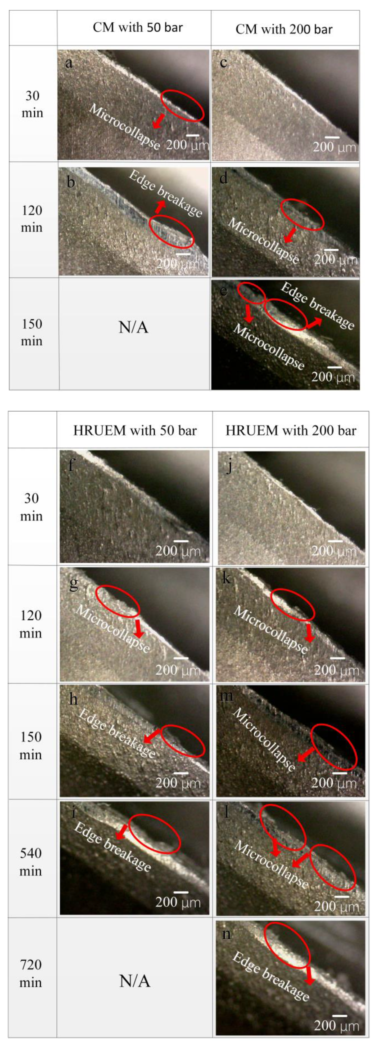
The most common wear mechanisms for cutting tools are mainly classified as adhesive wear, abrasive wear, oxidation wear and diffusion wear. In general, the dominant wear mechanism and failure modes depend on the cutting conditions, cutting tools and workpiece materials. Figure 11 shows some comparative micrographs of flank face in four cutting conditions: HRUEM with 200 bar, HRUEM with 50 bar, CM with 200 bar and CM with 50 bar at the same cutting speed of 120 m/min. At this cutting speed, the tool wear rate of the CM with 200 bar was slightly lower than that of the CM with 50 bar, while the tool wear rate of the HRUEM with 50 bar was greatly reduced. Moreover, when the cooling pressure was further increased, the tool wear rate of HRUEM with 200 bar decreased correspondingly.
Images of the tool flank wear in CM with 50 bar are presented in Figure 11a,b. It was found that the coating quickly wore out and a microcollapse occurred, and tool flank wear gradually intensified over time until the cutting edge failure. Figure 11c–e presents the tool flank faces of the CM with 200 bar and shows slower flank wear progression of the cutting edge than the CM with 50 bar. Figure 11f–i presents the tool flank faces of HRUEM with 50 bar. During the initial cutting stage, small notch wear was observed in the flank face, then notch wear and flank wear were intensified until the tool failure mode was changed to edge breakage. Tools in HRUEM showed a much smaller flank wear compared to CM at the same cutting duration. In addition, for HRUEM method, a 200 bar coolant could lead to a slower tool wear rate than the one with 50 bar coolant. As shown in Figure 11j–n, it took about 720 min to reach the failure standard using HRUEM with 200 bar.
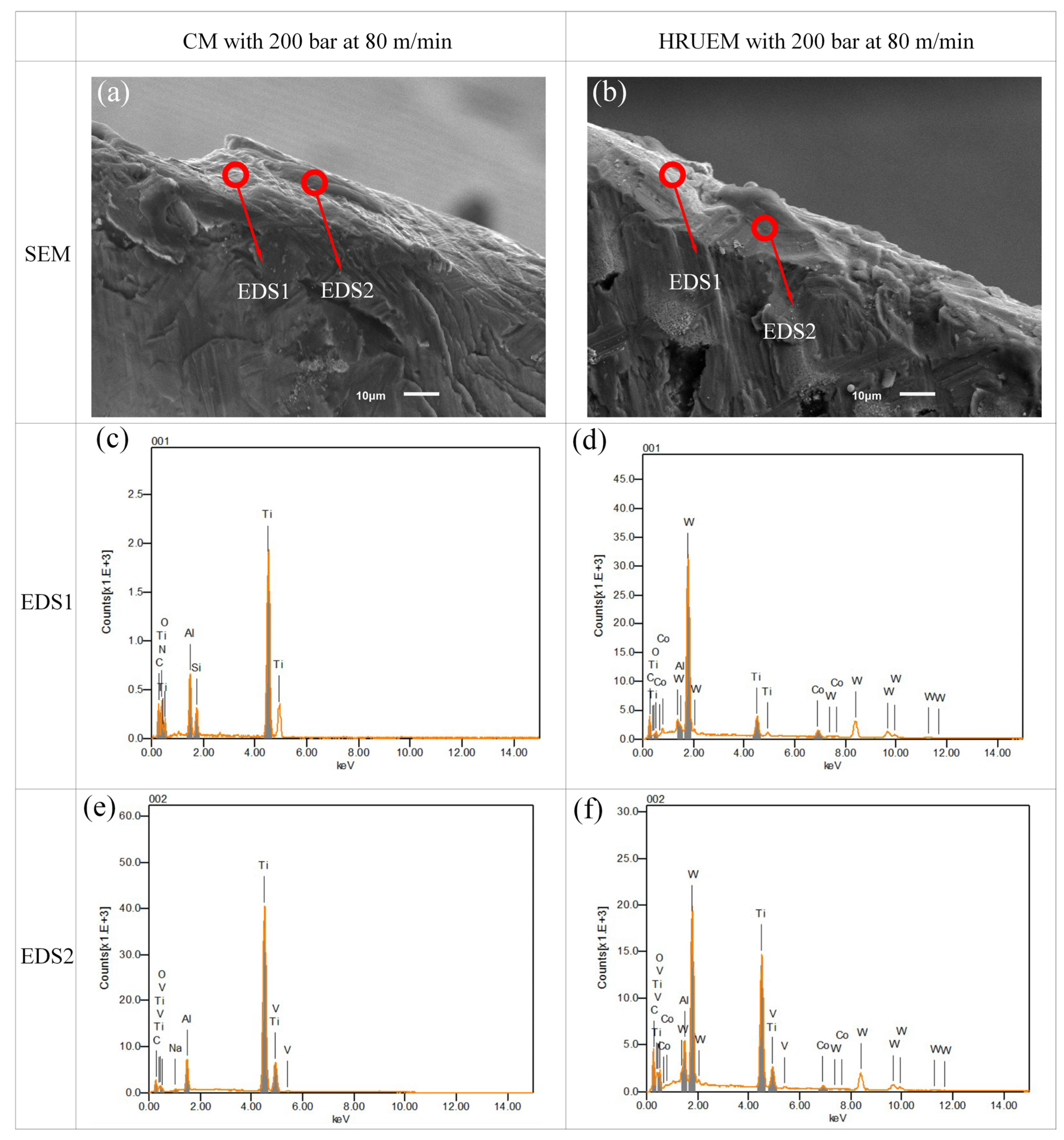
To study the tool wear mechanism in HRUEM with HPC, we took SEM micrographs of tool flank faces under various cutting conditions and conducted energy dispersive spectroscopy (EDS) analyses. As you can see in Figure 12a, a thick adhesion layer could be found on the tool flank face in CM with 200 bar, covering almost the whole wear area. Figure 12c,e indicates a very high concentration of Ti, the principle chemical element of the workpiece. The existence of the workpiece element on the whole wear face manifests indicates the presence of adhesive wear. In addition, considerable concentration of O was found in Figure 12c,e, providing the possibility of the presence of oxidation wear in this case.
Figure 12b shows the SEM photo of tool flank face in HRUEM with 200 bar. A bare tool surface was found on a part of the tool’s wear area. Figure 12d,f show the chemical composition of material in the bare area, respectively. A high concentration of W and C, the principle chemical element of the tool was found on the surface material, indicating that the wear was mainly caused by abrasion. Besides, the presence of O element indicates that oxidation wear may also occur in HRUEM with HPC.
High temperature in the cutting zone induced by poor lubrication can drastically intensify adhesion wear and even introduces oxidation wear. For high-speed machining in CM with HPC, the cutting heat accumulated quickly with a low cooling efficiency, resulting in a high temperature in cutting zone. Hence, the cutting tool wore quickly for adhesion and oxidation wear. In contrast, when HPC was applied in HRUEM, the cooling efficiency would be significantly enhanced with high-pressure coolant and tool-workpiece separation. We could say that the cutting temperature could be effectively reduced, thus significantly restraining adhesion wear. It could be concluded that compared to CM with HPC, HRUEM with HPC could effectively reduce adhesion wear. This can explain the significantly extended tool life of HRUEM with HPC compared to that of CM with HPC.

5. Conclusions

This paper investigated the effects of high-pressure coolant (HPC) on the cutting performance of high-speed rotary ultrasonic elliptical milling (HRUEM) in terms of tool life, MRV, cutting temperature and the tool wear mechanism. Moreover, the tool-workpiece separation cooling mechanism in HRUEM was also theoretically analyzed. The primary conclusions are summarized as follows:
(1)
The tool life was significantly extended in both CM and HRUEM by using HPC and the effect of cooling enhanced as the coolant pressure escalated. However, the cooling effect in HRUEM was much greater than that in CM under same coolant condition. At the coolant pressure of 200 bar, the tool life in HUREM was 7.6 times of that in CM at 80 m/min, 5.2 times of that in CM at 120 m/min and 3.4 times of that in CM at 160 m/min.
(2)
At 200 bar HPC and 80 m/min cutting speed, the MRV of HRUEM increased by about 657% compared to that of CM. In contrast of the CM at a cutting speed of 80 m/min and 200 bar HPC, the MRV in HRUEM at the cutting speed of 160 m/min and 200 bar HPC went up by about 135% and the material removal rate (MRR) was also doubled in HRUEM. Therefore, HRUEM with HPC was an effective method for milling of titanium alloys with high efficiency.
(3)
When the cutting speed was 80 m/min with 200 bar HPC, the cutting temperature of the workpiece in HRUEM was reduced by 24.1% compared to that of CM. The significant temperature reduction in HRUEM was a result of much higher heat convection efficiency between the cutting edge and coolant by the intermittent cutting mode achieved in this method.
(4)
HPC could offer a cooling effect and lubrication effect for tools in CM, however, the coolant still failed to reach the cutting edge, resulting in tool wear modes of severe adhesion wear and oxidative wear in CM. When HPC was applied in HRUEM, the cooling and lubrication efficiency could be significantly enhanced with the combination of high-pressure coolant and tool-workpiece periodic separation. As a result, the tool wear mode of adhesive wear was able to significantly inhibit in HRUEM.

Author Contributions

Conceptualization, M.Z.; Formal analysis, M.Z. and J.L.; Funding acquisition, D.G.; Methodology, Z.G. and H.G.; Project administration, D.Z. and D.G.; Resources, D.Z. and X.J.; Supervision, D.Z.; Writing—original draft, M.Z.; Writing—review and editing, M.Z. and D.G. All authors have read and agreed to the published version of the manuscript.

Funding

This research was funded by National Natural Science Foundation of China, grant No. 51905024, 51975035 and 91960203.

Conflicts of Interest

The authors declare no conflict of interest. The funders had no role in the design of the study; in the collection, analyses or interpretation of data; in the writing of the manuscript, or in the decision to publish the results.

References

  1. Ezugwu, E.O.; Wang, Z.M. Titanium alloys and their machinability a review. J. Mater. Process. Technol. 1997, 68, 262–274. [Google Scholar] [CrossRef]
  2. Moussaoui, K.; Mousseigne, M.; Senatore, J.; Chieragatti, R.; Lamesle, P. Influence of Milling on the Fatigue Lifetime of a Ti6Al4V Titanium Alloy. Metals 2015, 5, 1148–1162. [Google Scholar] [CrossRef]
  3. Thomas, M.; Turner, S.; Jackson, M. Microstructural damage during high-speed milling of titanium alloys. Scr. Mater. 2010, 62, 250–253. [Google Scholar] [CrossRef]
  4. Su, H.; Liu, P.; Fu, Y.; Xu, J. Tool Life and Surface Integrity in High-speed Milling of Titanium Alloy TA15 with PCD/PCBN Tools. Chin. J. Aeronaut. 2012, 25, 784–790. [Google Scholar] [CrossRef] [Green Version]
  5. Li, Y.; Zheng, G.; Zhang, X.; Cheng, X.; Yang, X.; Xu, R. Cutting force, tool wear and surface roughness in high-speed milling of high-strength steel with coated tools. J. Mech. Sci. Technol. 2019, 33, 5393–5398. [Google Scholar] [CrossRef]
  6. Mantle, A.L.; Aspinwall, D.K. Surface integrity of a high speed milled gamma titanium aluminide. J. Mater. Process. Technol. 2001, 118, 143–150. [Google Scholar] [CrossRef]
  7. Venugopal, K.A.; Paul, S.; Chattopadhyay, A.B. Growth of tool wear in turning of Ti-6Al-4V alloy under cryogenic cooling. Wear 2007, 262, 1071–1078. [Google Scholar] [CrossRef]
  8. Li, A.; Zhao, J.; Luo, H.; Pei, Z.; Wang, Z. Progressive tool failure in high-speed dry milling of Ti-6Al-4V alloy with coated carbide tools. Int. J. Adv. Manuf. Technol. 2011, 58, 465–478. [Google Scholar] [CrossRef]
  9. Sharma, V.S.; Dogra, M.; Suri, N.M. Cooling techniques for improved productivity in turning. Int. J. Mach. Tools Manuf. 2009, 49, 435–453. [Google Scholar] [CrossRef]
  10. Ke, Y.-L.; Dong, H.-Y.; Liu, G.; Zhang, M. Use of nitrogen gas in high-speed milling of Ti-6Al-4V. Trans. Nonferr. Met. Soc. China 2009, 19, 530–534. [Google Scholar] [CrossRef]
  11. Su, Y.; He, N.; Li, L.; Li, X.L. An experimental investigation of effects of cooling/lubrication conditions on tool wear in high-speed end milling of Ti-6Al-4V. Wear 2006, 261, 760–766. [Google Scholar] [CrossRef]
  12. Koklu, U.; Basmaci, G. Evaluation of Tool Path Strategy and Cooling Condition Effects on the Cutting Force and Surface Quality in Micromilling Operations. Metals 2017, 7, 426. [Google Scholar] [CrossRef] [Green Version]
  13. Lv, D.; Xu, J.; Ding, W.; Fu, Y.; Yang, C.; Su, H. Tool wear in milling Ti40 burn-resistant titanium alloy using pneumatic mist jet impinging cooling. J. Mater. Process. Technol. 2016, 229, 641–650. [Google Scholar] [CrossRef]
  14. Lu, Z.; Zhang, D.; Zhang, X.; Peng, Z. Effects of high-pressure coolant on cutting performance of high-speed ultrasonic vibration cutting titanium alloy. J. Mater. Process. Technol. 2020, 279, 116584. [Google Scholar] [CrossRef]
  15. Kovacevic, R.; Cherukuthota, C.; Mazurkiewicz, M. High pressure waterjet cooling/lubrication to improve machining efficiency in milling. Int. J. Mach. Tools Manuf. 1995, 35, 1459–1473. [Google Scholar] [CrossRef]
  16. Bermingham, M.J.; Palanisamy, S.; Morr, D.; Andrews, R.; Dargusch, M.S. Advantages of milling and drilling Ti-6Al-4V components with high-pressure coolant. Int. J. Adv. Manuf. Technol. 2014, 72, 77–88. [Google Scholar] [CrossRef]
  17. Diniz, A.E.; Micaroni, R. Influence of the direction and flow rate of the cutting fluid on tool life in turning process of AISI 1045 steel. Int. J. Mach. Tools Manuf. 2007, 47, 247–254. [Google Scholar] [CrossRef]
  18. Zheng, K.; Liao, W.; Dong, Q.; Sun, L. Friction and wear on titanium alloy surface machined by ultrasonic vibration-assisted milling. J. Braz. Soc. Mech. Sci. Eng. 2018, 40, 411. [Google Scholar] [CrossRef]
  19. Maurotto, A.; Wickramarachchi, C.T. Experimental investigations on effects of frequency in ultrasonically-assisted end-milling of AISI 316L: A feasibility study. Ultrasonics 2016, 65, 113–120. [Google Scholar] [CrossRef]
  20. Niu, Y.; Jiao, F.; Zhao, B.; Wang, D. Multiobjective optimization of processing parameters in longitudinal-torsion ultrasonic assisted milling of Ti-6Al-4V. Int. J. Adv. Manuf. Technol. 2017, 93, 4345–4356. [Google Scholar] [CrossRef]
  21. Ni, C.; Zhu, L.; Liu, C.; Yang, Z. Analytical modeling of tool-workpiece contact rate and experimental study in ultrasonic vibration-assisted milling of Ti–6Al–4V. Int. J. Mech. Sci. 2018, 142–143, 97–111. [Google Scholar] [CrossRef]
  22. Tsai, M.Y.; Chang, C.T.; Ho, J.K. The Machining of Hard Mold Steel by Ultrasonic Assisted End Milling. Appl. Sci. 2016, 6, 373. [Google Scholar] [CrossRef] [Green Version]
  23. Niu, Y.; Jiao, F.; Zhao, B.; Gao, G.F. Investigation of Cutting Force in Longitudinal-Torsional Ultrasonic-Assisted Milling of Ti-6Al-4V. Materials 2019, 12, 1955. [Google Scholar] [CrossRef] [PubMed] [Green Version]
  24. Lago, J.; Trsko, L.; Jambor, M.; Novy, F.; Bokuvka, O.; Mician, M.; Pastorek, F. Fatigue Life Improvement of the High Strength Steel Welded Joints by Ultrasonic Impact Peening. Metals 2019, 9, 619. [Google Scholar] [CrossRef] [Green Version]
  25. Brehl, D.E.; Dow, T.A. Review of vibration-assisted machining. Precis. Eng. 2008, 32, 153–172. [Google Scholar] [CrossRef]
  26. Liu, J.; Jiang, X.; Han, X.; Zhang, D. Influence of parameter matching on performance of high-speed rotary ultrasonic elliptical vibration-assisted machining for side milling of titanium alloys. Int. J. Adv. Manuf. Technol. 2018, 101, 1333–1348. [Google Scholar] [CrossRef]
  27. Geng, D.; Liu, Y.; Shao, Z.; Zhang, M.; Jiang, X.; Zhang, D. Delamination formation and suppression during rotary ultrasonic elliptical machining of CFRP. Compos. Part B Eng. 2020, 183, 107698. [Google Scholar] [CrossRef]
  28. Geng, D.; Liu, Y.; Shao, Z.; Lu, Z.; Cai, J.; Li, X.; Jiang, X.; Zhang, D. Delamination formation, evaluation and suppression during drilling of composite laminates: A review. Compos. Struct. 2019, 216, 168–186. [Google Scholar] [CrossRef]
  29. Liu, J.; Jiang, X.; Han, X.; Gao, Z.; Zhang, D. Effects of rotary ultrasonic elliptical machining for side milling on the surface integrity of Ti-6Al-4V. Int. J. Adv. Manuf. Technol. 2018, 101, 1451–1465. [Google Scholar] [CrossRef]
  30. Zhang, M.; Zhang, D.; Geng, D.; Shao, Z.; Liu, Y.; Jiang, X. Effects of tool vibration on surface integrity in rotary ultrasonic elliptical end milling of Ti–6Al–4V. J. Alloys Compd. 2019, 821, 153266. [Google Scholar] [CrossRef]
  31. Astakhov, V.P. 5-High-Pressure Supply of Metalworking Fluids. In Metalworking Fluids (MWFs) for Cutting and Grinding; Astakhov, V.P., Joksch, S., Eds.; Woodhead Publishing: Sawston, UK, 2012; pp. 201–290. [Google Scholar] [CrossRef]
  32. Astakhov, V.P. Tribology of Metal Cutting; Elsevier: Amsterdam, The Netherlands, 2006. [Google Scholar]
  33. Su, G.-S.; Guo, Y.-K.; Song, X.-L.; Tao, H. Effects of high-pressure cutting fluid with different jetting paths on tool wear in cutting compacted graphite iron. Tribol. Int. 2016, 103, 289–297. [Google Scholar] [CrossRef]
  34. Zhang, M.; Zhang, D.; Geng, D.; Liu, J.; Shao, Z.; Jiang, X. Surface and sub-surface analysis of rotary ultrasonic elliptical end milling of Ti-6Al-4V. Mater. Des. 2020, 191, 108658. [Google Scholar] [CrossRef]
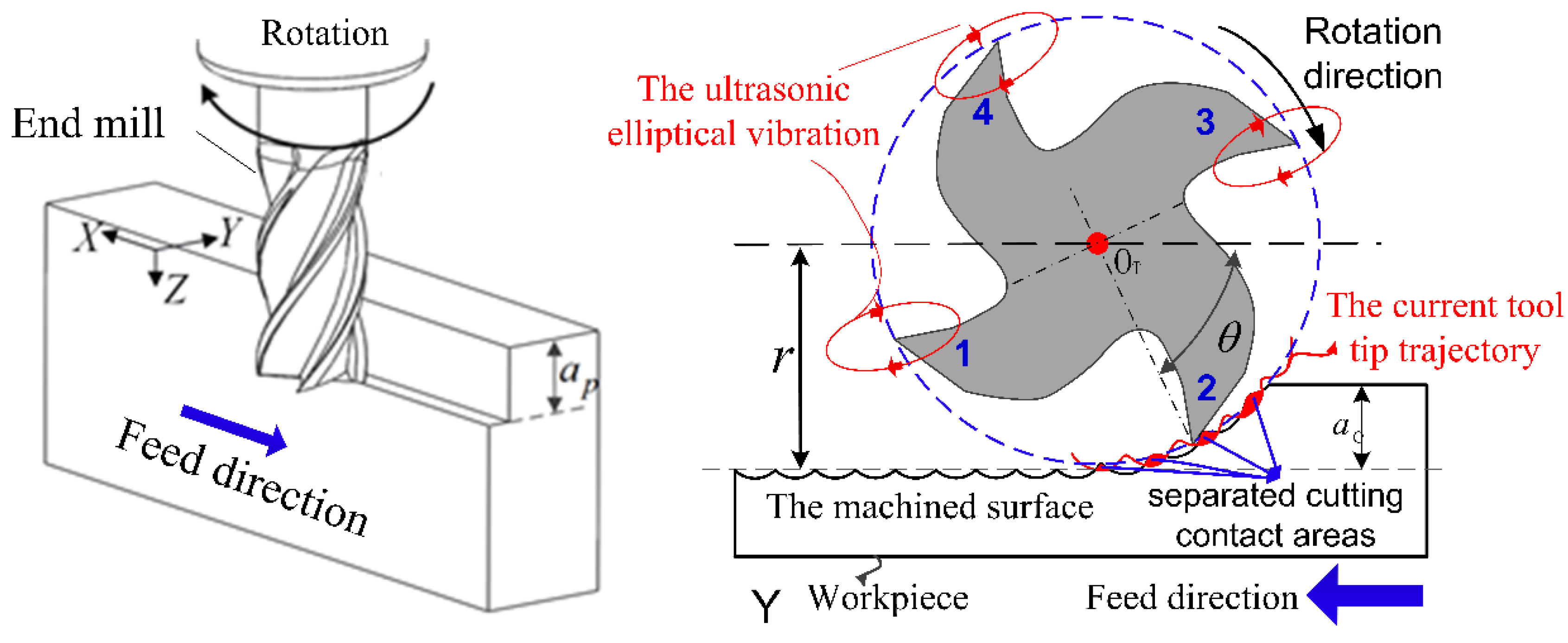
Figure 1. High-speed rotary ultrasonic elliptical milling (HRUEM) process with a four-flute end mill.
Metals 10 00500 g001
Figure 2. Trajectories of the tool tips in HRUEM.
Metals 10 00500 g002
Figure 3. Relative relationships of adjacent tool tip trajectories: (a) K = 1 π arcsin f z cos θ 2 A ; (b) 1 π arcsin f z cos θ 2 A < K < 1 1 π arcsin f z cos θ 2 A and (c) K = 1 1 π arcsin f z cos θ 2 A .
Metals 10 00500 g003
Figure 4. Cooling mechanism in HRUEM with a high-pressure coolant (HPC).
Metals 10 00500 g004
Figure 5. Heat transmission on the tool: (a) conventional milling (CM) with HPC and (b) HRUEM with HPC in non-cutting duration.
Metals 10 00500 g005
Figure 6. Microstructure of Ti-6Al-4V. Adapted from [34].
Metals 10 00500 g006
Figure 7. (a) Platform of HRUEM with HPC and (b) schematic diagram of the temperature measurement.
Metals 10 00500 g007
Figure 8. The variation of flank wear under different coolant pressures and cutting speeds in both HRUEM and CM: (a) v = 80   m / min , (b) v = 120   m / min and (c) v = 160   m / min .
Metals 10 00500 g008
Figure 9. The variation of material removal volume (MRV) under different coolant pressures cooling conditions and cutting speeds in both HRUEM and CM.
Metals 10 00500 g009
Figure 10. Relationship between the temperature and cutting speed at different cooling conditions.
Metals 10 00500 g010
Figure 11. Micrographs of tools in CM and HRUEM with different cooling conditions at cutting speed of 120 m/min: (a,b) CM with 50 bar, (ce) CM with 200 bar, (fi) HRUEM with 50 bar and (jn) HRUEM with 50 bar.
Metals 10 00500 g011
Figure 12. SEM micrographs and EDS analyses of CM and HRUEM with 200 bar: (a) SEM micrographs of CM, (b) SEM micrographs of HRUEM, (c) EDS1 analyses of CM, (d) EDS1 analyses of HRUEM, (e) EDS2 analyses of CM and f EDS2 analyses of HRUEM.
Metals 10 00500 g012
Table 1. Physical and mechanical properties of Ti-6Al-4V alloy at room temperature.
MaterialDensity (kg/m3)Hardness (HV)Elastic Modulus (GPa)Melting Temperature (°C)Thermal Conductivity (W/mK)Yield Strength (MPa)
Ti-6Al-4V4429.0320.0114.01667.06.70835.0
Table 2. Conditions of the end mill.
Base MaterialCoatingNumber of Cutting EdgesDiameter (mm)Helix Angle (°)Rake Angle (°)Relief Angle (°)
CarbideTiAlN41238108
Table 3. Conditions of end milling experiments in CM and HRUEM.
Milling ConditionsAxial cutting depth a p (mm)0.2
Radial cutting depth a e (mm)5
Feed speed per tooth f z (mm/z)0.015
Nominal cutting speed v (m/min)80, 120, 160
Type of millingCM and HRUEM
Vibration ConditionsAmplitudes A and B ( μ m) A = 5 and B = 6
Frequency (Hz)17,880
Angle shift ( ° )90
Cooling Conditionscoolant pressure (bar)50, 200