Communication

Assessment of Internal Stresses Using Dislocation Dipole Heights in Cyclically Deformed [001] Copper Single Crystals

1
Mork Family Department of Chemical Engineering and Materials Science, University of Southern California, Los Angeles, CA 90089, USA
2
CEA Paris-Saclay, DMN-SRMA, Bat. 455, 91191 Gif-sur-Yvette CEDEX, France
*
Author to whom correspondence should be addressed.
Metals 2020, 10(4), 512; https://doi.org/10.3390/met10040512
Submission received: 21 March 2020 / Revised: 9 April 2020 / Accepted: 12 April 2020 / Published: 15 April 2020

Abstract

:
There have been a number of studies on dipole separations in cyclically deformed FCC single crystals in single slip while there are no such studies in multiple slip. The dipole heights provide insight into the presence of long-range internal stresses (LRIS). In this study, we investigated how LRIS compare with the single slip studies through measuring the dislocation of dipole heights. [001] oriented copper single crystals were cyclically deformed in strain-control to saturation at ambient temperature. Transmission electron microscopy (TEM) confirms a labyrinth dislocation microstructure with high dislocation density walls and low dislocation density channels. The maximum dipole heights under the saturation stress were approximately independent of location, being nearly equal in the walls and within the channels. This, by itself, supports a uniform stress across the microstructure and low long-range internal stresses. The maximum value for dipole heights suggests dipole strengths (local stresses) that are about a factor of 2.4 higher than the applied stress based on the usual athermal equations. Considering the small “extra” stress that may be provided by tripoles or small dislocation pile-ups, a nearly homogenous stress distribution with only small internal stresses may be present, which is consistent with the observation of uniform dipole height across the heterogeneous dislocation microstructure. This observation that the stress state appears to be homogenous and higher than the applied stress has also been reported in the case of cyclically deformed metals in single slip.

Graphical Abstract

1. Introduction

When FCC metals are cyclically deformed along a [001] direction (tension and compression with R = −1), a labyrinth microstructure consisting of dislocation walls and channels (regions with high and low dislocation densities, respectively) develops. The details of these dislocation structures strongly depend on the strain amplitude, crystal orientation, temperature, and number of cycles [1,2,3,4]. The labyrinth microstructure was first observed in a polycrystalline Cu-Ni alloy fatigued in multiple glide by Charsley and Kuhlmann-Wilsdorf [5] and then observed by Jin and Winter [6] for the first time in single crystals in cyclically deformed [001] oriented copper (multiple slip). The purpose of this work is to determine the microstructure of cyclically deformed copper single crystal oriented for multiple slip at ambient temperature along the [001] tensile axis and to measure the dislocation dipole heights across the heterogeneous dislocation microstructure. This will allow for an investigation into the existence of long-range internal stresses (LRIS) in the labyrinth structure. Figure 1 depicts the dipole height, which is the distance between the two slip planes of the dislocation dipole. Understanding LRIS is essential for a variety of reasons including understanding the basis of the Bauschinger effect, spring back in metal forming, and, of course, understanding the plastic deformation of cyclically deformed metals (fatigue) [7,8].
There are no known studies of measurement of dipole heights in polyslip. Sauzay and Kubin [9], in a review article on the dislocation microstructures in cyclically deformed FCC metals, note that there are no publications in which dislocation densities were measured in fatigued crystals oriented for multiple slip. Previous works on FCC single crystals oriented for single slip include Kassner et al. [10,11,12,13] on Al and Cu, Antonopoulos et al. [14] on Cu, and Tippelt et al. [15] on Ni. All of these studies discovered that the dipole heights in the walls and the channels were nearly equal. One interpretation is that the stress-state may be homogenous since the stress required to separate the widest dipole is a measure of the local stress (wider separation dipoles are unstable), and these are the same in the walls and the channels. (It should be noted that according to Essmann and Mughrabi [16], edge dipoles eliminate spontaneously in the walls if separated by <1.6 nm in copper.) As just mentioned, maximum dipole heights represent the upper limit of stable dipoles under the imposed stress. Thus, local stresses in cyclically deformed materials may be predicted. In this study, the maximum dipole heights of both walls as well as those of the channels were measured. The stress to separate (or “break”) an infinite edge dipole, assuming isotropic elasticity, can be evaluated by the formula:
τ = G b 8 π   ( 1 ν )   h
where G is the shear modulus, ν is Poisson’s ratio, b is the Burgers vector, and h is the dipole height. This equation will be discussed in greater detail in the results and discussion section.
Kassner et al. [12] suggested a homogenous but elevated stress about 2.7 times larger than the applied stress in a fatigued copper single crystal oriented for single slip at ambient temperature. Their interpretation is that differences between the applied stress and local stress suggested by maximum dipole height may be rationalized by thermal activation or small dislocation pile-ups. In another study by Kassner et al. [11], single crystal Al was cyclically deformed in single slip at 77 K. They demonstrated that the strength is consistently about 0.8 of the applied stress based on the maximum dipole height; this is nearly a perfect match between the dipole separation stress and the applied shear stress, strongly suggesting an absence of LRIS using Equation (1), which has limitations since it is relevant for infinite-length dipoles. As will be discussed in the discussion section, dipoles are finite and this equation is limited. Maximum dipole separations in fatigued Ni crystals cyclically deformed in single slip at ambient temperature also predict a homogenous but elevated stress about 4 times the flow stress [15]. The present work intends to investigate the LRIS trends through dipole separation measurements for multiple slip in single crystal copper. Most investigators [15,17,18], as reviewed in [8], suggest that, using in-situ TEM dislocation loop radii measurements and asymmetry measurements in X-ray peaks, the LRIS in the high dislocation density heterogeneities varies from a factor of 1.0 (no LRIS) to 3, or more, larger than the applied stress.

2. Materials and Methods

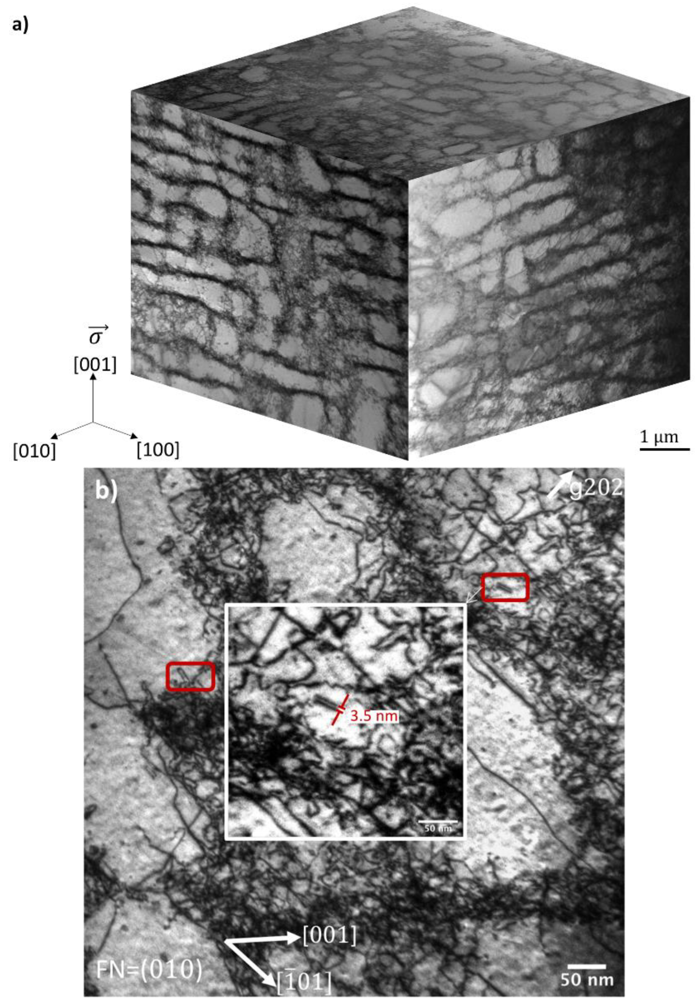
[001]-oriented copper single crystals of 99.999% purity were cyclically deformed in tension/compression at 298 K to 157 cycles at a strain amplitude of 4.0 × 10⁻³ and a strain rate of 2 × 10⁻³ s−1. Schmid factors for this polyslip were 0.408 (with 8 potentially active slip systems). The crystal was fatigued to saturation with an axial stress of 275 MPa and a resolved shear stress of 112 MPa in the <110> direction on a {111} plane. Figure 2a illustrates the stress versus strain behavior and Figure 2b demonstrates the maximum and minimum peak stresses with respect to the number of cycles. A continuous hardening was observed and it occurred very quickly–that is, during the first 20 cycles. Then, the cyclic hardening rate decelerated until a maximum peak stress was observed at the 108th cycle. After that, a very slow softening was observed up until the 157th cycle. Disks (3 mm) from the (001), (010), and (100) planes were electropolished with a Fischione twin jet (Fischione Instruments Inc., Export, PA, USA) using 10% nitric acid and 90% methanol at −20 °C. The specimens were examined in bright field using the JEM-2100F transmission electron microscope (TEM) (JEOL Inc., Peabody, MA, USA) at the University of Southern California at an accelerating voltage of 200 kV. A total of 100 dipole heights were measured. As the reviewer of this manuscript pointed out to the authors, this sample may be somewhat small considering the higher population of small h dipoles [19]. The error in dipole height measurements was estimated to be ±1.0 nm. Dipoles were identified as two parallel dislocations with similar lengths in the <112> direction. In order to obtain the dipole height, which is defined as the distance between the <111> slip planes of the two dislocations of a dipole, the spacing between the dislocation lines in foils with a normal of (010) needs to be projected on to a single {111} plane. Although secondary dipoles were observed in cyclically deformed single slip Cu single crystals, only primary dipole heights were measured; secondary dipoles were rarely observed [13]. In this article, determination of the nature of the dipoles in terms of vacancy or interstitial type was not attempted. Figure 3 depicts the 3-dimensional microstructure of the fatigued copper containing dislocation walls and channels. The stress axis is parallel to the vertical [001] direction. The specimens were stored in liquid nitrogen to prevent static recovery/recrystallization of the dislocation substructure [20,21].

3. Results and Discussion

Figure 3 illustrates that the microstructure of fatigued [001] copper single crystal consists of a labyrinth and cellular structure. Both structures consist of relatively evenly spaced walls and channels with a much lower dislocation density. This heterogeneous structure has been referred to, by some, as ‘‘hard’’ regions with high dislocation density and ‘‘soft’’ regions with low dislocation density [17,18]. The labyrinth structure was only uniquely identified on (010) planes where all the dipole height measurements were performed. Due to small misorientations by low angle dislocation tilt boundaries in the crystal, the “perfect” labyrinth structure may not be observed. The average channel width was approximately 0.36 µm at a shear stress of 112 MPa and the volume fraction of the channels was about 70%. The average wall width was 0.12 µm. The channel widths were smaller than what has been reported in earlier studies of the dislocation wall and channel structures due to the higher amount of applied shear stress (e.g., a channel width of 0.52 µm at a shear stress of 44 MPa [6] and a channel width of 0.57 µm at a shear stress of 50 MPa [1] both for [001] single crystal copper).
In the current study, the dislocation density in the walls was 8.6 × 10¹⁴ m/m3 and the density in the channels was 1.55 × 10¹³ m/m3 using Equation (2) [22]. In this equation, N is the number of dislocation intersections with a random line of length, L, and t is the thickness of the film, which was determined by electron energy loss spectroscopy.
ρ = 2 N L t
Kassner et al. [11] reported a dislocation density of 1.3 × 10¹⁵ m−2 and 8.3 × 10¹² m−2 in the walls and channels, respectively, for a cyclically deformed single crystal copper in single slip to pre-saturation to a shear stress of 19 MPa where all of the dislocations were dipoles. Thus, dipoles did in fact control the flow stress. In this study, where copper is cyclically deformed under multiple slip, more non-dipole dislocations were available than dipoles. Therefore, the authors expect that the total dislocation density controls the stress and the dipoles are just a reflection of what the stress is.
As mentioned earlier, maximum dipole heights represent the upper limit of stable dipoles under the imposed stress. Therefore, they can predict the local stresses in cyclically deformed materials. The maximum dipole height in the walls and channels was 4.3 nm and 4 nm, respectively, and the top 10% of the maximum dipole heights in the walls was 3.3 nm and in the channels was 3.5 nm. This is analogous to what earlier studies found in fatigued copper, aluminum, and nickel with single slip [10,11,12,13,15]. A homogenous stress state within the crystal can be interpreted since the local stresses based on the maximum dipole heights are nearly identical in the walls and channels. This suggests that the internal stresses are minimal. An Orowan–Sleeswyk-type mechanism, which involves no internal stresses, could be the underlying basis for the Bauschinger effect that was observed with each reversal [7]. The mechanism may be responsible for the observed saturation at a very low stress compared to the true (monotonic) fracture stress [7,23,24].
Choosing h = 4.15 nm, G = 46.5 GPa, and ν = 0.355, Equation (1) predicts a dipole-breaking value of 177 MPa, which is higher than the remote shear stress of 112 MPa. That is in line with various estimates made by Kassner and co-workers showing that the dipole separation stress is generally higher than the remote shear stress value, in both hard and soft regions [13]. At 77 K, aluminum was the exception, with a pre-saturation vein and channel microstructure [11]. In this case, based on Equation (1), which as mentioned earlier has its limitations, the dipole separation stress and the applied shear stress are almost the same.
Existing literature suggests negligible differences in stress between hard and soft phases but a much higher dipole separation stress than expected based on dislocation dipole height measurements, dislocation loop radii, and asymmetry in X-ray peaks [12,15,17,18]. In the following paragraphs, three considerations are noted, which the authors believe should be incorporated into Equation (1).
1. Contrary to nickel and copper, aluminum crystals obey almost isotropic elasticity. In aluminum, the Zener anisotropy ratio amounts to 1.1, very close to 1. The Zener ratio reaches 2.5 in nickel and 3.3 in copper, respectively [9]. The introduction of cubic elasticity in Equation (1) makes a difference between almost isotropic aluminum and anisotropic nickel and copper. For this purpose, the anisotropic values of the shear modulus and the Poisson’s ratio proposed by Bacon and Scattergood were used [25]. For copper at 300 K, the numerical application provides anisotropic values of G = 42.1 GPa and ν = 0.431, which differ from their isotropic elasticity counterparts (G = 46.5 GPa and ν = 0.355, respectively). For nickel, the difference remains but is lower due to a lower anisotropy than copper. For aluminum, both values are very close as expected in this almost isotropic metal. The use of the Bacon and Scattergood effective parameters in Equation (1) does not significantly change the dipole separation stress, which reaches 180 MPa. In fact, a lower shear modulus and a higher Poisson ratio act in opposite ways in Equation (1). This small effect (here around 5 MPa) of the anisotropy of cubic elasticity was confirmed by the dislocation dynamics simulation studies carried out by Veyssière and Chiu on copper [26].
2. Aluminum’s normalized stacking fault energy (SFE) is higher than that of nickel and copper (Table 1). This implies that the distance between the head and queue partial dislocations is shorter in aluminum than in nickel while copper has the greatest distance in comparison with the other two. Differences in the forces between the two opposite edge dislocations are expected because each of them is now split into two partial dislocations. This may explain the specific behavior of aluminum (almost equal dipole separation stress and applied stress) with respect to nickel and copper. It should also be noted that in aluminum, the extinction distance is 2 or 3 times larger than it is for copper, depending upon the reflections chosen [27]. This means that it is more difficult to obtain an estimate of the maximum dipole height in aluminum. We once more refer to the work of Veyssière and Chiu [26], who not only assessed the effect of cubic elasticity but also considered SFE. Based on the 2D dislocation dynamics simulations of dipole separation stress in copper, partial dissociation only has a visible effect on the dipole separation stress in dipole heights lower than 2.5 nm. Since in our study the maximum dipole heights are 4 nm, the dissociations would not influence the dipole separation stress [26]. It can be concluded that for the metals considered in Table 1, only small increases in the edge dipole separation stress are induced by dislocation dissociation, even in copper. In this case, the “conflicting” results exhibited by Kassner and coworkers, which were observed in copper but not in aluminum, cannot be the effect of the stacking fault distance alone.
3. Finally, another characteristic of dipoles in a fatigued microstructure should be discussed. Authors agree that the dipole length is finite and its aspect ratio, h/L, ranges between 1/15 and 1/10 [9,15]. Careful examination of the maximum dipole heights provides a mean value of the aspect ratio, h/L, of 1/11 in the wall and channel regions of the labyrinths here. We now refer to the discrete dislocation dynamics computations of Sauzay and Dupuy, where a nodal DDD code was used [28]. Various prismatic loops were built that take large ranges of the L and h parameters into consideration. The two long primary dislocations of length L are indeed linked together by short collinear dislocation segments corresponding to the h height. For each prismatic loop, a shear stress was applied to the instability of each prismatic loop. It was found that a correction factor, C (h,h/L), allows for the rewriting of Equation (1), which is only valid for infinite edge dipoles. Equation (3) was obtained based on numerous DDD computation results:
τ d = C ( h , h / L ) G b 8 π   ( 1 ν )   h
Equation (3) was used to evaluate the dipole separation stress in this study. Using h = 4.15 nm and h/L = 1/11, a pre-factor C of 1.5 was found [28]. Then, introducing the Bacon and Scattergood elasticity parameters mentioned above for Cu [25], a dipole separation stress as high as 270 MPa was found. That is about 2.4 times higher than the applied shear stress.
Therefore, none of the three topics discussed here–cubic elasticity, dissociation into two partial dislocations, nor finite aspect ratio of edge dipoles–allows for the evaluation of an edge dipole separation stress lower than the one predicted by the classical formula concerning infinite edge dipoles without dislocation dissociation and assuming isotropic elasticity. All of the results are summarized in Table 1 using Equation (1) and the Bacon and Scattergood effective elasticity coefficients. As stated previously, only in the pre-saturation vein-channel microstructure of single slip aluminum at 77 K are the evaluated dipole separation stress and the applied one comparable. Tripoles or small dislocation pile-ups (just two to three dislocations) blocked at dipoles may lead to such a local increase in shear stress [29,30].
Further nodal DDD computations accounting for the separation of the dislocations into two partial dislocations and the finite aspect ratio of dipoles may be of interest to assess the synergy between both effects. It has been noticed previously that the evolution of the separation stress changes drastically around h = 2.5 nm in copper for infinite edge dipoles. Therefore, the synergy between both may lead to slightly different results. Finally, based on both our evaluation of the effect of the anisotropy of cubic elasticity in copper and nickel and the one carried out by Veyssiere and Chiu [26] in various conditions, it can be concluded that it is not an order one parameter for the edge dipole separation stress evaluation.
As stated, the stress required to separate the dipoles with the maximum height was calculated to be 270 MPa from Equation (3). Wider dipole heights than hmax would be unstable under the local stress. The dipole stress for the maximum height of 270 MPa suggests a stress about a factor of 2.4 larger than the applied stress. Kassner et al. [12] have reported this ratio to be 2.7 for fatigued copper at shear stress of 19 MPa in single slip, and Tippelt et al. [15] reported a value close to 4 for cyclically deformed nickel at shear stress of 50 MPa in single slip. It should again be noted that in both of these studies dislocation dipoles are assumed to have an infinite length. All values are presented in Table 1. It is suggested that stress raisers, such as small dislocation pile-ups, can increase the local stress. Brown [19] suggests that an infinite dipole approached by a single dislocation can be broken up by an applied stress that is half of that required if the dipole is isolated. This is the “tripole” effect of Neumann [29,30] and is also related to Veyssiere’s [26] notions of athermal dipole refinement. Thus, one expects the ratio in line 7 of Table 1 to be 2; this is not far from what was observed.

4. Conclusions

The maximum dislocation dipole heights were nearly equal in the channels and walls of the labyrinth structure for cyclically deformed [001] copper single crystals oriented for multiple slip to stress saturation. This is the first study that examined dipole heights in cyclically deformed metals in multiple slip. Our observations lead to the conclusion of a uniform stress distribution with low internal stresses as the stress to separate the widest dipoles is independent of the location. However, the widest dipole strengths correspond to a shear stress of about 2.4 of the applied stress. Similar behaviors (homogenous dipole heights and higher dipole separation stresses) have also been reported for cyclically deformed metal single crystals in single slip in other studies. The fact that the calculated separation stress based on the dipole height is larger than the applied stress based on Equation (3) may be explained by tripoles or mild dislocation pile-ups. As a final note, our earlier synchrotron work on monotonically deformed copper single crystals [35] found that long-range internal stresses were about 10% of the applied stress. Thus, the results of the current cyclic deformation study are consistent with the earlier monotonic deformation work.

Author Contributions

M.E.K. conceived of and designed the project; R.E., M.S., and M.E.K. contributed to theoretical analysis and conceptualization; M.S. prepared the fatigued samples and was involved in fundamental discussions with M.E.K.; R.E prepared the TEM samples and performed TEM studies and data analysis; Literature searches were performed by R.E.; Manuscript preparation and proof-reading were performed by R.E., M.S., and M.E.K. All authors have read and agreed to the published version of the manuscript.

Funding

This research was funded by the National Science Foundation under grant DMR-1401194.

Acknowledgments

The authors greatly appreciate the assistance of Mark Wall and Matthew Mecklenburg. The authors also truly appreciate the constructive comments made by the reviewers including providing the authors with the alternative values of stacking fault energies to the ones that have been originally listed and additional relevant references.

Conflicts of Interest

The authors declare no conflict of interest.

References

  1. Fujii, T.; Kajita, T.; Miyazawa, T.; Arai, S. Characterization of dislocation microstructures in cyclically deformed [001] copper single crystals using high voltage scanning transmission electron microscopy. Mater. Charact. 2018, 136, 206–211. [Google Scholar] [CrossRef]
  2. Wang, Z.; Gong, B.; Wang, Z. Cyclic deformation behavior and dislocation structures of [001] copper single crystals—II. Characteristics of dislocation structures. Acta Mater. 1997, 45, 1379–1391. [Google Scholar] [CrossRef]
  3. Gong, B.; Wang, Z.; Wang, Z. Cyclic deformation behavior and dislocation structures of [001] copper single crystals—I cyclic stress-strain response and surface feature. Acta Mater. 1997, 45, 1365–1377. [Google Scholar] [CrossRef]
  4. Li, P.; Li, S.X.; Wang, Z.G.; Zhang, Z.F. Fundamental factors on formation mechanism of dislocation arrangements in cyclically deformed fcc single crystals. Prog. Mater. Sci. 2011, 56, 328–377. [Google Scholar] [CrossRef]
  5. Charsley, P.; Kuhlmann-wilsdorf, D. Configuration of {100} dislocation walls formed during fatigue. Philos. Mag. A. 1981, 44, 1351–1361. [Google Scholar] [CrossRef]
  6. Jin, N.Y.; Winter, A.T. Dislocation structures in cyclically deformed [001] copper crystals. Acta Metall. 1984, 32, 1173–1176. [Google Scholar] [CrossRef]
  7. Levine, L.E.; Stoudt, M.R.; Creuziger, A.; Phan, T.Q.; Ruqing, X.; Kassner, M.E. Basis for the Bauschinger effect in copper single crystals: Changes in the long-range internal stress with reverse deformation. J. Mater. Sci. 2019, 54, 6579–6585. [Google Scholar] [CrossRef]
  8. Kassner, M.E.; Geantil, P.; Levine, L.E. Long range internal stresses in single-phase crystalline materials. Int. J. Plast. 2013, 45, 44–60. [Google Scholar] [CrossRef]
  9. Sauzay, M.; Kubin, L.P. Scaling laws for dislocation microstructures in monotonic and cyclic deformation of fcc metals. Prog. Mater. Sci. 2011, 56, 725–784. [Google Scholar] [CrossRef]
  10. Kassner, M.E.; Wall, M.A.; Delos-Reyes, M.A. Microstructure and mechanisms of cyclic deformation of aluminum single crystals at 77 K. Metall. Mater. Trans. A 1997, 28, 595–609. [Google Scholar] [CrossRef]
  11. Kassner, M.E.; Wall, M.A. Microstructure and mechanisms of cyclic deformation in aluminum single crystals at 77 K: Part II. Edge dislocation dipole heights. Metall. Mater. Trans. A 1999, 30, 777–779. [Google Scholar] [CrossRef]
  12. Kassner, M.E.; Wall, M.A.; Delos-Reyes, M.A. Primary and secondary dislocation dipole heights in cyclically deformed copper single crystals. Mater. Sci. Eng. A 2001, 317, 28–31. [Google Scholar] [CrossRef]
  13. Kassner, M.E.; Pérez-Prado, M.T.; Vecchio, K.S.; Wall, M.A. Determination of internal stresses in cyclically deformed copper single crystals using convergent-beam electron diffraction and dislocation dipole separation measurements. Acta Mater. 2000, 48, 4247–4254. [Google Scholar] [CrossRef]
  14. Antonopoulos, J.G.; Winter, A.T. Weak-beam study of dislocation structures in fatigued copper. Philos. Mag. 1976, 33, 87–95. [Google Scholar] [CrossRef]
  15. Tippelt, B.; Breitschneider, J.; Hähner, P. The Dislocation Microstructure of Cyclically Deformed Nickel Single Crystals at Different Temperatures. Phys. Status Solidi 1997, 163, 11–26. [Google Scholar] [CrossRef]
  16. Essmann, U.; Mughrabi, H. Annihilation of dislocations during tensile and cyclic deformation and limits of dislocation densities. Philos. Mag. A 1979, 40, 731–756. [Google Scholar] [CrossRef]
  17. Mughrabi, H. Dislocation wall and cell structures and long-range internal stresses in deformed metal crystals. Acta Metall. 1983, 31, 1367–1379. [Google Scholar] [CrossRef]
  18. Mughrabi, H. A two-parameter description of heterogeneous dislocation distributions in deformed metal crystals. Mater. Sci. Eng. 1987, 85, 15–31. [Google Scholar] [CrossRef]
  19. Brown, L.M. A discussion of the structure and behaviour of dipole walls in cyclic plasticity. Philos. Mag. 2004, 84, 2501–2520. [Google Scholar] [CrossRef]
  20. Kassner, M.E.; Pollard, J.; Evangelista, E.; Cerri, E. Restoration mechanisms in large-strain deformation of high purity aluminum at ambient temperature and the determination of the existence of ‘steady-state’. Acta Metall. Mater. 1994, 42, 3223–3230. [Google Scholar] [CrossRef]
  21. Kassner, M.E.; McQueen, H.J.; Pollard, J.; Evangelista, E.; Cerri, E. Restoration mechanisms in large-strain deformation of high purity aluminum at ambient temperature. Scripta Metall. Mater. 1994, 31, 1331–1336. [Google Scholar] [CrossRef]
  22. Ham, R.K. The determination of dislocation densities in thin films. Philos. Mag. 1961, 6, 1183–1184. [Google Scholar] [CrossRef]
  23. Orowan, E. Causes and effects of internal stresses. Internal Stresses and Fatigue in MetalsRassweiler, G.M., Grube, W.L., Eds.; General Motors SymposiumElsevier: Amsterdam, The Netherlands, 1959; pp. 59–80. [Google Scholar]
  24. Sleeswyk, A.W.; James, M.R.; Plantinga, D.H.; Maathuis, W.S.T. Reversible strain in cyclic plastic deformation. Acta Metall. 1978, 26, 1265–1271. [Google Scholar] [CrossRef]
  25. Scattergood, R.O.; Bacon, D.J. The Orowan mechanism in anisotropic crystals. Philos. Mag. 1975, 31, 179–198. [Google Scholar] [CrossRef]
  26. Veyssiere, P.; Chiu, Y.L. Equilibrium and passing properties of dislocation dipoles. Philos. Mag. 2007, 87, 3351–3372. [Google Scholar] [CrossRef]
  27. Fultz, B.; Howe, J. Transmission Electron Microscopy and Diffractometry of Materials, 3rd ed.; Springer: Berlin/Heidelberg, Germany, 2013; p. 344. [Google Scholar]
  28. Sauzay, M.; Dupuy, L. Internal Stresses in Deformation-Induced Microstructures; XXIV ICTAM: Montreal, QC, Canada, 2016. [Google Scholar]
  29. Neumann, P.D. The interactions between dislocations and dislocation dipoles. Acta Metall. 1971, 19, 1233–1241. [Google Scholar] [CrossRef]
  30. Neumann, P.D. Constitutive Equations in Plasticity; Argon, A.S., Ashby, M.F., Eds.; MIT Press: Cambridge, UK, 1975. [Google Scholar]
  31. Haasen, P. Physical Metallurgy; Cambridge Press: London, UK, 1978; p. 116. [Google Scholar]
  32. Brown, L.M. A dipole model for the cross-slip of screw dislocations in FCC metals. Philos. Mag. A. 2002, 82, 1691–1711. [Google Scholar] [CrossRef]
  33. Forwood, C.T.; Humble, P. Dislocartion dipoles in elastically anisotropic crystals. Aust. J. Phys. 1970, 23, 697–718. [Google Scholar] [CrossRef] [Green Version]
  34. Wintner, E.; Karnthaler, H.P. The study of dipoles in Cu-Al alloys using weak-beam electron microscopy. Philos. Mag. 1977, 36, 1317–1329. [Google Scholar] [CrossRef]
  35. Levine, L.E.; Larson, B.C.; Yang, W.; Kassner, M.E.; Tischler, J.Z.; Delos-Reyes, M.A.; Fields, R.J. X-ray microbeam measurements of individual cell elastic strains in deformed single crystal copper. Nat. Mater. 2006, 5, 619–622. [Google Scholar]
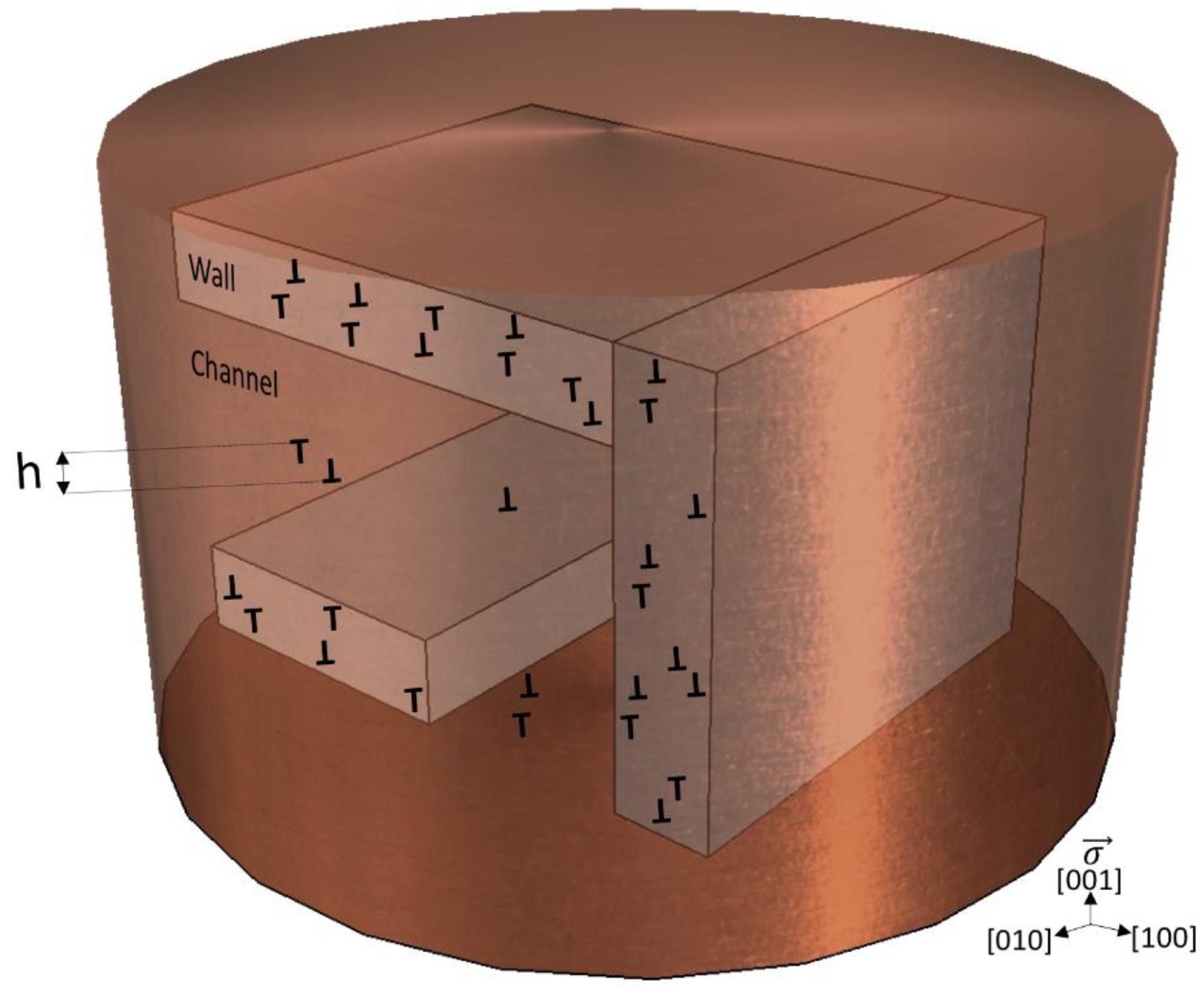
Figure 1. A three-dimensional (3-D) schematic representation of the dislocation structure illustrating the dipole height “h”.
Metals 10 00512 g001
Figure 2. (a) The cyclic deformation of [001]-oriented copper single crystal at ambient temperature. Strains are plastic and elastic. (b) The evolution of the maximum and minimum peak stress with respect to the number of cycles.
Metals 10 00512 g002
Figure 3. (a) Transmission electron microscope “cube” based on images taken from the (100), (010), and (001) planes of a specimen cyclically deformed to saturation as illustrated in Figure 1. The stress axis is parallel to the vertical direction [001]. (b) A part of the labyrinth structure showing dislocation dipoles.
Metals 10 00512 g003
Table 1. Dipole heights and stress calculations (Equation (1) for [11,13,15] and Equation (3) for this study) based on observed maximum “h” values.
This Study (Cu)Cu [13]Al [11]Ni [15]
Labyrinth WallsLabyrinth ChannelsDipole Bundles (Veins)ChannelsDipole Bundles (Veins)ChannelsPSB WallsPSB Channels
Maximum Dipole Height (nm)4.341512313267.1
Dipole Stress for hmax (MPa)270 (h = 4.15)52 (h = 13.5)16 (h = 31.5)186.6 (h = 6.55)
Applied Resolved Shear Stress (MPa)112192050
saturationhalf of saturation stresspre-saturationsaturation
τda (for hmax)2.42.70.83.7
Slippolyslipsingle slipsingle slipsingle slip
SFE mJ/m2 [31,32,33,34]606020090
T/Tm0.220.220.120.17
Strain Amplitude0.40%Plastic only = 0.125%Plastic only = 0.12%0.40%
Strain Rate2 × 10−32.5 × 10−32 × 10−410−3
Number of Cycles157200560-