Article

Microstructure Evolution of 5052 Aluminum Sheet in Electromagnetic High-Speed Impact

1
School of Mechanical and Electrical Engineering, Wuhan Institute of Technology, Wuhan 430205, China
2
College of Materials Science and Engineering, Huazhong University of Science and Technology, Wuhan 430074, China
3
Hubei Tri-Ring Forging Co., Ltd., Xiangyang 441700, China
4
School of Materials Science and Engineering, Hubei University of Automotive Technology, Shiyan 442002, China
*
Author to whom correspondence should be addressed.
Metals 2020, 10(5), 564; https://doi.org/10.3390/met10050564
Submission received: 13 March 2020 / Revised: 13 April 2020 / Accepted: 24 April 2020 / Published: 27 April 2020

Abstract

:
Electromagnetic forming (EMF) is a high-speed forming technology, which can not only improve the formability of hard-to-form materials but also reduce springback. Electromagnetic high-speed impact can further improve the formability compared with electromagnetic free forming. The microscopic deformation mechanism of electromagnetic high-speed impact of aluminum alloy is discussed in this paper. The microstructures of electromagnetic high-speed impact of an aluminum alloy sheet were characterized. The microscopic deformation mechanisms of electromagnetic forming and electromagnetic high-speed impact were shown, respectively. The research results showed that electromagnetic high-speed impact could significantly improve the microhardness of the workpiece. The grains broke up and then became small subgrains during electromagnetic high-speed impact. The deformation mechanism was dominated by dislocation cross slip under electromagnetic high-speed impact.

1. Introduction

Aluminum alloy sheets are widely used in vehicles and airplanes because of the advantage of fuel economy and reduced environmental pollution [1,2]. However, aluminum alloy sheets are prone to cracking due to their low formability at room temperature in traditional stamp forming processes. Additionally, large springback tends to occur, which affects forming precision [3]. Therefore, fracture and large rebound seriously restrict the wide application of aluminum alloy sheets in the manufacturing industry.
Electromagnetic forming (EMF), a high-speed forming technology, can not only improve formability but also reduce springback [4,5]. The formability of aluminum alloy sheets in high speed forming had been studied by many researchers. The electromagnetic ring expansion process of AA6061-T4 and pure copper was investigated by Tamhane et al. [6], and a doubled formability was reported, comparing it with the formability in quasi-static (QS) forming. By comparing the forming limits of Ti-6Al-4V and AA5052-O under QS and EMF, Li et al. [7] observed a formability increase by 24.37% and 10.97%, respectively, in EMF. It was reported by Vohnout [8] that the formability of 6111-T4 and 5754-O aluminum alloy was improved by QS preforming followed by high-speed forming. Liu et al. [9] also reported formability improvement beyond conventional forming of 5052-O aluminum alloy in high-velocity forming after a QS preforming step.
Electromagnetic high-speed impact could further improve formability compared with electromagnetic free forming, and electromagnetic high-speed impact has also been researched by many researchers. Mala Seth [10] found that the fracture strain of steel sheet was significantly increased compared with electromagnetic free forming because of the sheet’s high-speed impact to the die. Golovashchenko [11] reported the electromagnetic high-speed impact of aluminum alloy based on different shaped dies, and found that the specimen elongation, which was formed by electromagnetic high-speed impact, was about 2.5 times higher than that by quasi-static forming. Imbert et al. [12] reported that the formability of 5754 aluminum alloy was evidently higher with electromagnetic high-speed impact to the die than electromagnetic free forming, and significant increases in formability were attributed to the interaction between the sheet and the die.
Research results showed that the formability of aluminum alloy was improved with electromagnetic high-speed impact under certain boundary conditions, for example, under compressive stress, under a high strain rate, and under an optimized strain path. The deformation mechanisms of aluminum alloy under EMF or high-speed tension were studied by scholars [13,14] who found that multi-slips and homogenization effects of dislocations were the microscopic deformation mechanisms in high-speed deformation. However, few scholars paid attention to the microscopic deformation mechanisms of aluminum alloy under electromagnetic high-speed impact. Therefore, the microscopic deformation mechanism of electromagnetic high-speed impact of 5052 aluminum alloy is discussed in this paper. The microstructure of electromagnetic high-speed impact of aluminum alloy sheet is characterized. The microscopic deformation mechanisms of electromagnetic high-speed impact are revealed.

2. Experimental Conditions

2.1. Material

The material used in the experiment was the 5052-O aluminum alloy sheet. It is widely utilized in the aerospace and automobile fields. The diameter of the sheet in the experiment was 210 mm, and the thickness was 2 mm. The main chemical composition and mechanical properties of the material are shown in Table 1 and Table 2, respectively.

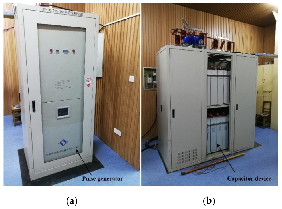
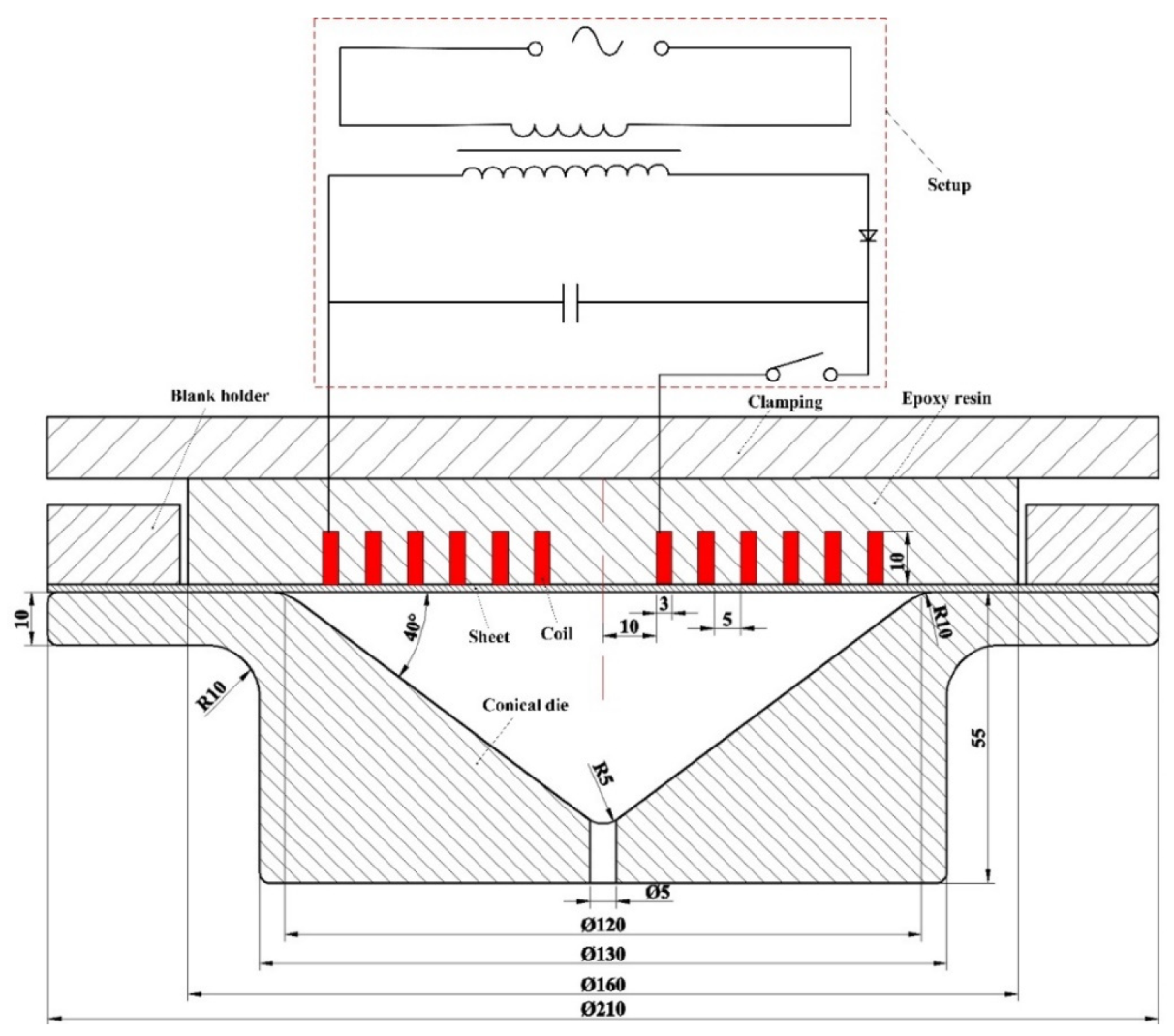
2.2. Electromagnetic High-Speed Impact Experiment

Figure 1 shows the EMF equipment, which consisted of a pulse generator and a capacitor device. The pulse generator was mainly composed of a power supply and a control system, as shown in Figure 1a. The capacitor device mainly consisted of a series of capacitor banks, as shown in Figure 1b. The EMF equipment had a maximum energy capacity of 200 kJ at the maximum charging voltage of 30 kV, and a maximum capacitance of 4.26 × 10⁻⁴ F. This equipment set was made by the Huazhong University of Science and Technology in China.
The experimental setup of electromagnetic high-speed impact of 5052 aluminum alloy was shown in Figure 2. The sheet was placed on the top of the conical die, and the flange region of the sheet was restrained by the blank holder. A flat spiral coil was placed above the sheet. The experimental setup of the electromagnetic high-speed impact is schematically shown in Figure 3. When the stored energy was discharged, the pulse current passed through the coil and induced an eddy in the sheet, generating a dynamic Lorentz’s force, which pushed the sheet deformation downwards. The diameter of the flat spiral coil was 106 mm. The inner diameter of the coil was 10 mm. The coil had a six-turn rectangular cross-section shape, and the cross-section size was 3 × 10 mm. The distance between every two turns was 5 mm. A conical die was used in the electromagnetic high-speed impact experiment. The cone base diameter of the conical die was 120 mm, with an entry radius of 10 mm, a tip radius of 5 mm, and a cone angle of 40°.
The sidewall and center region of the specimen impacted to the conical die at a high speed when the coil discharged. In order to consider the impact characteristics in EMF, the deformed workpiece was divided into four parts (region A, B, C, and D). Region A, which was considered to be the initial material zone, was located at the flange area of the workpiece, as shown in Figure 4. Region B was located at the half radius of the coil. Region D was located at the workpiece center, and region C was between region B and region D. The high-speed impact process of electromagnetic forming is schematically shown in Figure 5. Region B firstly impacted to the sidewall of the die due to the maximum electromagnetic force that appeared at the half radius of the coil. Region D impacted to the tip of the conical die at high speed under the inertia force. However, region C did not impact to the conical die at high speed because there was no magnetic pressure existing at this region. Region C gradually deformed along with the deformation of region B [15]. The electromagnetic formed specimen during high-speed impact was shown in Figure 4. The specimens were split for microstructure characterization after electromagnetic high-speed impact.

2.3. Micro Hardness Test

Samples with the size of 6 mm × 5 mm were cut from the electromagnetic high-speed impact workpiece. The samples were inlaid and then were ground with abrasive papers of #400, #800, #1200, and #2000 sequentially. Finally, the samples were mechanically polished. The Vickers hardness values of samples were obtained by the digital micro hardness tester (430SVD, Buehler Co., Lake Bluff, IL, USA). The positions of the micro hardness test were along the center line of the sample cross section. The load and duration time were set at 9.8 N and 15 s, respectively. The micro hardness was calculated by the average value of six points on each sample section. The error of hardness measurement was claimed to be ±0.75%.

2.4. Electron Back Scattering Diffraction Test

The test samples for the electron back scattering diffraction (EBSD) test were ground with silicon carbide abrasive papers of #400, #800, #1200, #2000, and #4000 sequentially. Then, the samples were polished with W1.0 diamond grinding paste. The sample microstructures were characterized by EBSD with a MAIA3 XMH field emission gun scanning electron microscope (FEG-SEM, TESCAN, MAIA3 XMH, Brno, Czech Republic). This experiment setup was equipped with an EBSD system. A 20 kV operating voltage and 12 mm working distance was used in low vacuum. A scan step of 0.8 μm was used for the measurements.

2.5. Transmission Electron Microscopy Test

The samples were burnished into 40 µm thickness foils with #400, #1000, and #2000 abrasive paper. Discs 3 mm in diameter were obtained by punching. Then, the oxide layer and surface residue were removed by an ion thinning apparatus (Gatan model 695, San Diego, CA, USA) to meet the requirements of the TEM test. Finally, a TEM (FEI Talos F200, Hillsboro, OR, USA) was used to observe the morphological characteristics of the samples.

3. Results and Discussions
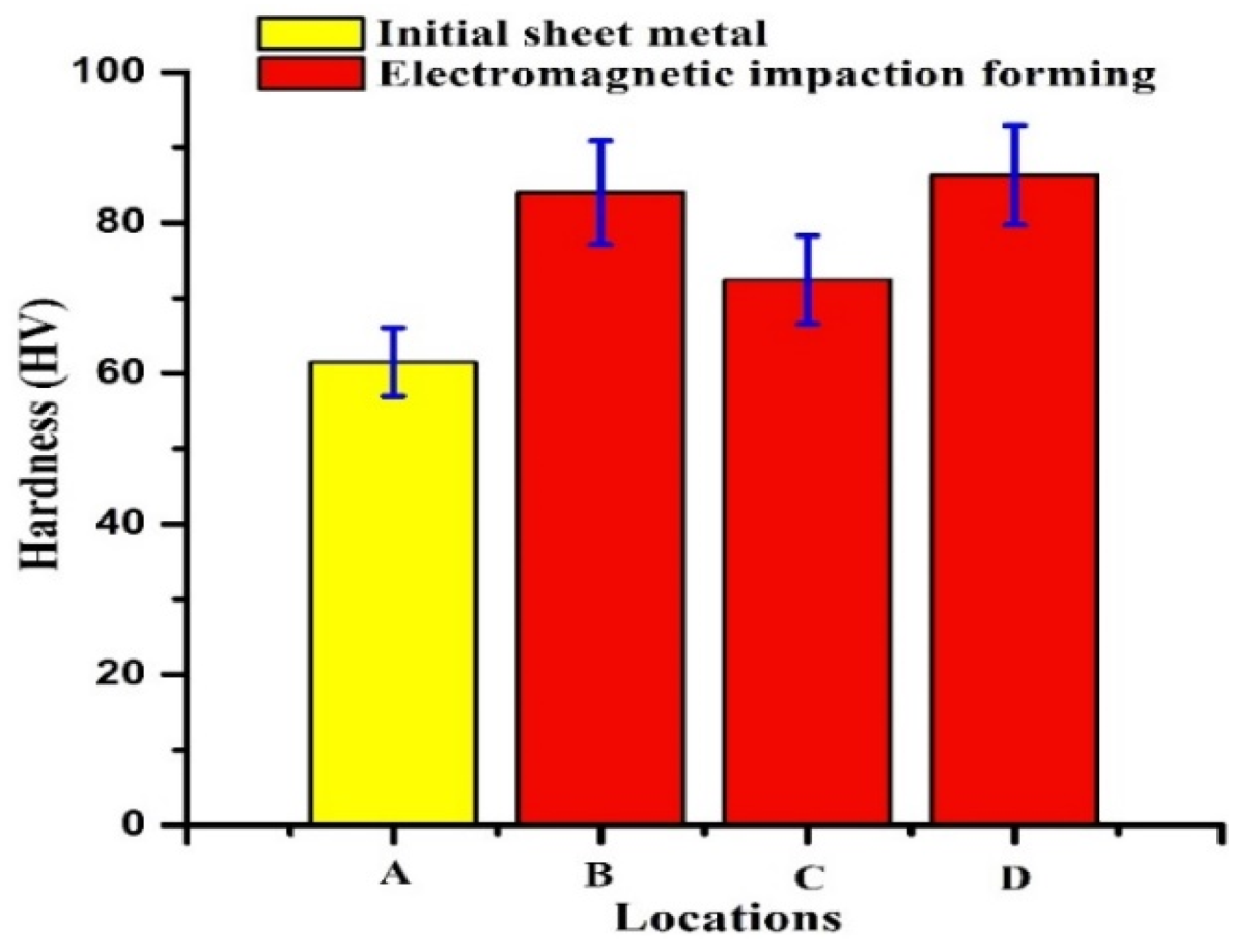
3.1. Micro Hardness

The micro hardness of different regions of the 5052 aluminum alloy sheet after electromagnetic high-speed impact forming is shown in Figure 6, and the micro hardness values are shown in Table 3. The micro hardness of the initial material (region A) was 62.0 HV. Region B was the first to be high-speed impacted to the conical die because region B was located at half the radius of the coil, which distributed the largest electromagnetic force; the micro hardness of region B increased to 85.0 HV. Although the plastic deformation amount of region C was larger than region B, it could be seen that the average micro hardness (73.5 HV) was lower. This could be because the sheet in region C did not experience high-speed impact to the conical die due to low magnetic pressure in region C [15]; the sheet in region C gradually adhered to the die surface along with the surrounding material. Thus, work hardening caused by high-speed impact would been occurred, as was found in region B. Region D was the center region of the sheet, which was high-speed impacted to the conical die under inertia forces. The micro hardness of region D increased significantly to 87.0 HV due to high-speed impact and large plastic deformation. The thicknesses of deformation regions B, C, and D were 1.82 mm, 1.76 mm, and 1.68 mm, respectively. To sum up, the results shown in Table 3 indicated that electromagnetic high-speed impact significantly improved the micro hardness of the workpiece.

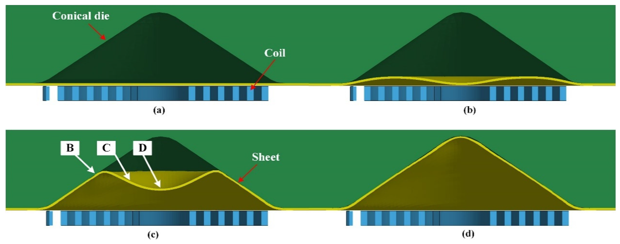
3.2. Discussion of the EBSD Results

The grain morphologies were obtained by the EBSD test in the three typical regions of the electromagnetic high-speed impact samples, as shown in Figure 7. It showed that the grain size in Figure 7b–d decreased in the process of electromagnetic forming compared with the initial grain size shown in Figure 7a. In addition, the grain morphology and the average size were changed significantly during electromagnetic high-speed impact compared with region A. Region B of the sheet impacted to the sidewall of the conical die at a high speed during electromagnetic discharge, and region B was subjected to severe compressive stress. Therefore, the grains appeared to be significantly elongated, and the grain size decreased significantly, as shown in Figure 7b. The grain morphology of region C was changed greatly compared with the initial state due to large plastic deformation. However, although region C was subjected to greater plastic deformation, the grain size did not decrease compared to region B. Therefore, high-speed impact would significantly reduce the grain sizes. There was no electromagnetic force in region D, and a serious impact between this region and the top of the conical die occurred due to the effect of inertia action. As seen in Figure 7d, the grains became flatter and smaller compared to region B, because the center region of the specimen impacted to the conical die more severely. Therefore, the center region of the workpiece was subjected to higher impact compressive stress, and the large contact stress led to the significant increase in hardness.
The percentage of average grain diameter and the number of grains are presented in Figure 8. The proportion of small-diameter grains obviously increased when the sheet high-speed impacted to the conical die. The grain size decreased substantially during the electromagnetic high-speed impact, as shown in Figure 8d, and more sliding systems were activated in this region.
It can be seen in Figure 7 that when the specimen impacted to the die at high speed, not only the grain morphology and size was changed, but also sub-grains were generated. The grains broke into small subgrains when the center of the sheet impacted to the conical die under inertial action, and a large number of small grains were formed during electromagnetic high-speed impact.

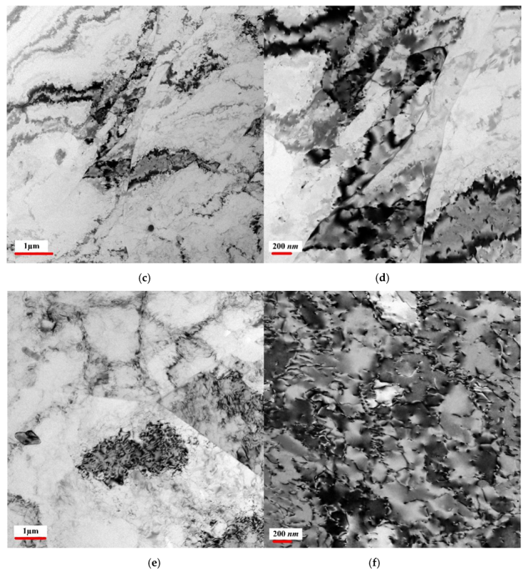
3.3. Discussion of the TEM Results

In order to understand the plastic deformation mechanism of the 5052 aluminum alloy sheet, it was necessary to analyze the microstructure evolution in electromagnetic high-speed impact. The TEM photograph of the undeformed specimen is presented in Figure 9a,b. The dislocation density was low in the original material. The TEM photographs of region C are shown in Figure 9c,d. Dislocation density of region C increased significantly compared with region A. The microstructure of the electromagnetic forming specimen mainly included dislocation bands, as shown in Figure 9d. Thus, the deformation mechanism was plane slip during electromagnetic forming.
As seen in Figure 9e, trigeminal grains appeared at region D. The dislocation density of region D increased significantly compared with region C. It can be seen in Figure 9f that the dislocation wall and dislocation cell were found in region D. Thus, at the microscopic level, dislocation cross slip was the deformation mechanism in electromagnetic high-speed impact forming. Therefore, the main deformation mechanisms in electromagnetic forming and in electromagnetic high-speed impact were both dislocation slip mechanisms, but the difference was that the deformation mechanism in electromagnetic forming was dislocation plane slip, and the deformation mechanism in electromagnetic high-speed impact was dislocation cross slip. The deformation mechanism in the present research was different from the results in the literature [13,14]. With increasing dislocation density, the orientation difference increased within deformed grain, and the increase of dislocation density led to the increase of micro hardness.

4. Conclusion

The micro hardness and microstructures of 5052 aluminum alloys were characterized after electromagnetic high-speed impact. The results of this work are summarized below.
Although the plastic deformation amount in region C was larger than that of region B, the average micro hardness was lower. Therefore, electromagnetic high-speed impact could significantly improve the micro hardness of the sheet.
When the specimen impacted to the die at a high speed, not only the grain morphology and size was changed, but also sub-grains were generated. The grains broke into small subgrains when the center of the sheet impacted to the conical die under inertial action
Large plastic deformation occurred in region C during electromagnetic forming, and the microstructure of region C was mainly dislocation bands. The deformation mechanism was dominated by a planar slip under electromagnetic forming. The microstructure of region D was mainly dislocation wall and dislocation cell after electromagnetic high-speed impact. Thus, the microscopic deformation mechanism was dislocation cross slip in electromagnetic high-speed impact.
Electromagnetic high-speed impact could improve the formability of hard-to-deform material. Therefore, it was of great significance to expand the application of electromagnetic high-speed impact in manufacturing of hard-to-deform parts in automotive and airplane applications. The microscopic mechanism, deformation behavior, and performance of the formed part of 5052 aluminum alloy by electromagnetic high-speed impact will be studied deeper in our future work.

Author Contributions

The research was conceived by F.F. and J.L. L.H., H.S., S.C., and G.S. planned and performed all the experiments. The experimental analysis were performed by Y.Z. and R.C. The manuscript was written by F.F. with support from all co-authors. All authors have read and agreed to the published version of the manuscript.

Funding

This work was supported by the National Natural Science Foundation of China (No. 51705169, 51575206, and 51435007), the Key Laboratory of Automotive Power Train and Electronic in Hubei University of Automotive Technology (ZDK1201903), and Hubei Provincial Key Laboratory of Chemical Equipment Intensification and Intrinsic Safety (2019KA01).

Conflicts of Interest

The authors declare no conflict of interest.

References

  1. Huda, Z.; Edi, P. Materials selection in design of structures and engines of supersonic aircrafts: A review. Mater. Des. 2013, 46, 552–560. [Google Scholar] [CrossRef]
  2. Dursun, T.; Soutis, C. Recent developments in advanced aircraft aluminum alloys. Mater. Des. 2014, 56, 862–871. [Google Scholar] [CrossRef]
  3. Cui, X.; Mo, J.; Li, J.; Xiao, X.; Zhou, B.; Fang, J. Large-scale sheet deformation process by electromagnetic incremental forming combined with stretch forming. J. Mater. Process. Technol. 2016, 237, 139–154. [Google Scholar] [CrossRef]
  4. Psyk, V.; Risch, D.; Kinsey, B.L.; Tekkaya, A.E.; Kleiner, M. Electromagnetic forming—A review. J. Mater. Process. Technol. 2011, 211, 787–829. [Google Scholar] [CrossRef]
  5. Li, C.; Liu, D.; Yu, H.; Ji, Z. Research on formability of 5052 aluminum alloy sheet in a quasi-static–dynamic tensile process. Int. J. Mach. Tools Manuf. 2009, 49, 117–124. [Google Scholar] [CrossRef]
  6. Tamhane, A.A.; Altynova, M.M.; Daehn, G.S. Effect of sample size on ductility in electromagnetic ring expansion. Scr. Mater. 1996, 34, 1345–1350. [Google Scholar] [CrossRef]
  7. Li, F.-Q.; Mo, J.-H.; Li, J.-J.; Huang, L.; Zhou, H.-Y. Formability of Ti–6Al–4V titanium alloy sheet in magnetic pulse bulging. Mater. Des. 2013, 52, 337–344. [Google Scholar] [CrossRef]
  8. Vohnout, V.J. A Hybrid Quasi-Static/Dynamic Process for Forming Large Sheet Metal Parts from Aluminum Alloys. Ph.D. Thesis, The Ohio State University, Columbus, OH, USA, 1998; p. 437. [Google Scholar]
  9. Liu, D.; Yu, H.; Li, C. Experimental observations of quasi-static-dynamic formability in biaxially strained AA5052-O. J. Mater. Eng. Perform. 2011, 20, 223–230. [Google Scholar] [CrossRef]
  10. Dehra, M.S. High Velocity Formability and Factors Affecting it. Ph.D. Thesis, The Ohio State University, Columbus, OH, USA, 2006. [Google Scholar]
  11. Golovashchenko, S.F. Material Formability and Coil Design in Electromagnetic Forming. J. Mater. Eng. Perform. 2007, 16, 314–320. [Google Scholar] [CrossRef]
  12. Imbert, J.M.; Winkler, S.L.; Worswick, M.J.; Oliveira, D.A.; Golovashchenko, S. The Effect of Tool–Sheet Interaction on Damage Evolution in Electromagnetic Forming of Aluminum Alloy Sheet. J. Eng. Mater. Technol. 2005, 127, 145–153. [Google Scholar] [CrossRef]
  13. Liu, D.H.; Yu, H.P.; Li, C.F. Comparative study of the microstructure of 5052 aluminum alloy sheets under quasi-static and high-velocity tension. Mater. Sci. Eng. A 2012, 551, 280–287. [Google Scholar] [CrossRef]
  14. Fang, J.; Mo, J.; Li, J. Microstructure difference of 5052 aluminum alloys under conventional drawing and electromagnetic pulse assisted incremental drawing. Mater. Charact. 2017, 129, 88–97. [Google Scholar] [CrossRef]
  15. Feng, F.; Huang, S.; Hu, J.; Meng, Z.; Lei, Y. Analysis of the bulging process of an AZ31B magnesium alloy sheet with a uniform pressure coil. Int. J. Adv. Manuf. Technol. 2013, 69, 1537–1545. [Google Scholar] [CrossRef]
Figure 1. EMF equipment: (a) pulse generator; (b) capacitor device.
Metals 10 00564 g001
Figure 2. Photograph of electromagnetic high-speed impact forming experimental setup.
Metals 10 00564 g002
Figure 3. Schematic of the electromagnetic high-speed impact forming experimental setup with a conical die.
Metals 10 00564 g003
Figure 4. The formed specimen after electromagnetic high-speed impact.
Metals 10 00564 g004
Figure 5. The deformation process of electromagnetic high-speed impact at various times: (a) t = 20 µs, (b) t = 90 µs, (c) t = 160 µs, (d) t = 300 µs.
Metals 10 00564 g005
Figure 6. The micro hardness of different regions of 5052 aluminum alloy sheet after electromagnetic high-speed impact forming.
Metals 10 00564 g006
Figure 7. The grain morphology of different regions of the sheet after electromagnetic high-speed impact: (a) region A, (b) region B, (c) region C, (d) region D.
Metals 10 00564 g007
Figure 8. The average grain diameter distribution of different regions of the sheet after electromagnetic high-speed impact: (a) region A, (b) region B, (c) region C, (d) region D.
Metals 10 00564 g008aMetals 10 00564 g008b
Figure 9. The TEM photograph of dislocation distribution of different regions in electromagnetic high-speed impact: (a,b) correspond to the initial material; (c,d) correspond to region C; (e,f) correspond to region D.
Metals 10 00564 g009aMetals 10 00564 g009b
Table 1. Chemical composition of 5052 aluminum alloy sheet.
ElementSiFeCuMnMgCrZnAl
Mass fraction (%)0.060.290.010.062.50.160.01Balanced
Table 2. Mechanical properties of AA5052 alloy.
Yield Strength (MPa)Ultimate Tensile Strength (MPa)Strain-Hardening Exponent (n)Total Elongation (%)
89.4268.50.250.325
Table 3. Vickers hardness of 5052 aluminum alloy sheet at different regions.
RegionABCD
Values62.085.073.587.0

