Analysis of the Drawing Process of Small-Sized Seam Tubes

Abstract
:1. Introduction
2. Materials and Methods
2.1. Material Characteristics
2.2. Manufacturing Process of the Seam Tube
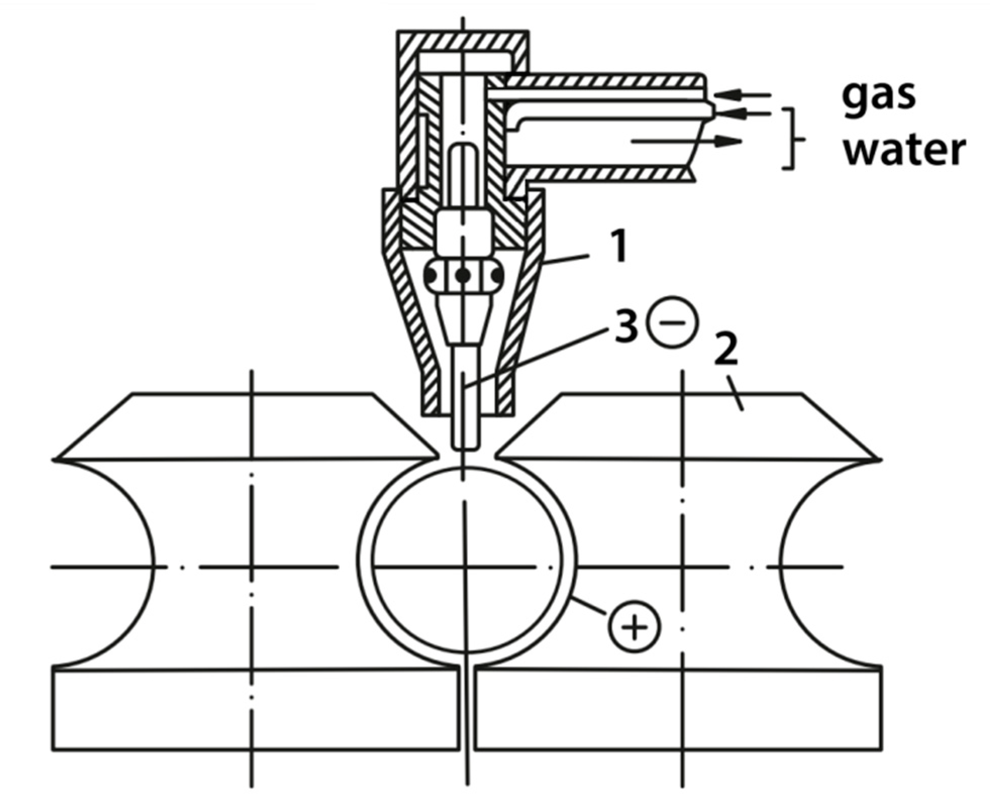
2.2.1. Welding Assembly
2.2.2. Stress States during Tube Drawing over a Floating Mandrel and without a Mandrel
3. Results
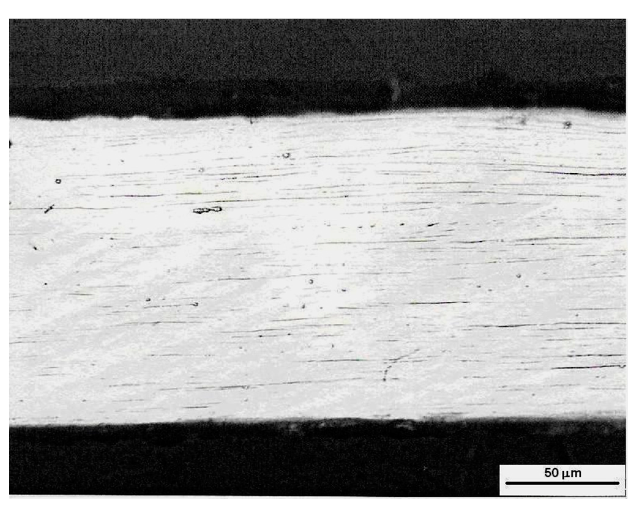
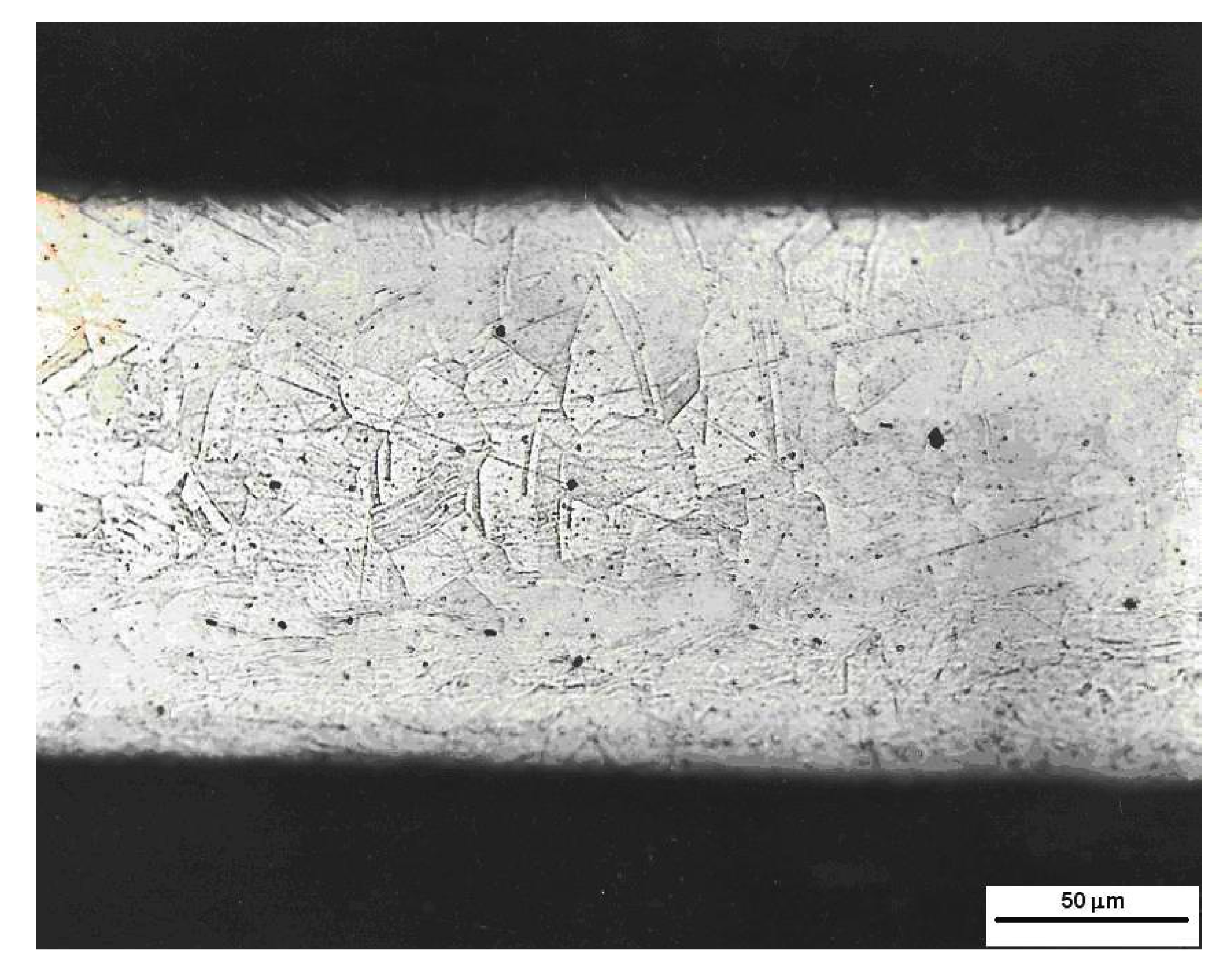
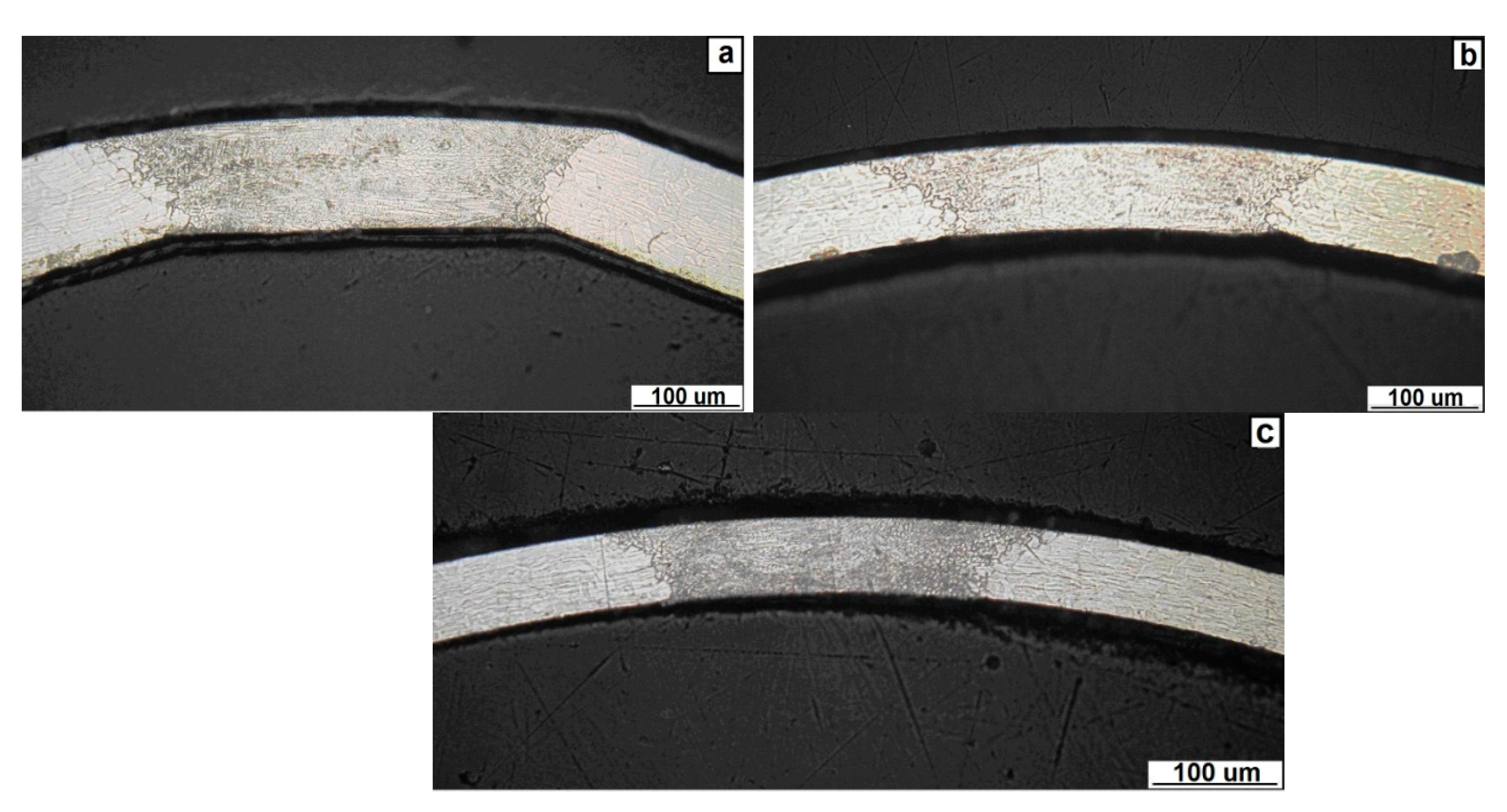
3.1. Microstructure Analysis
3.2. The Effect of Tube Eccentricity on the Drawing Process
- Processing of the ribbon;
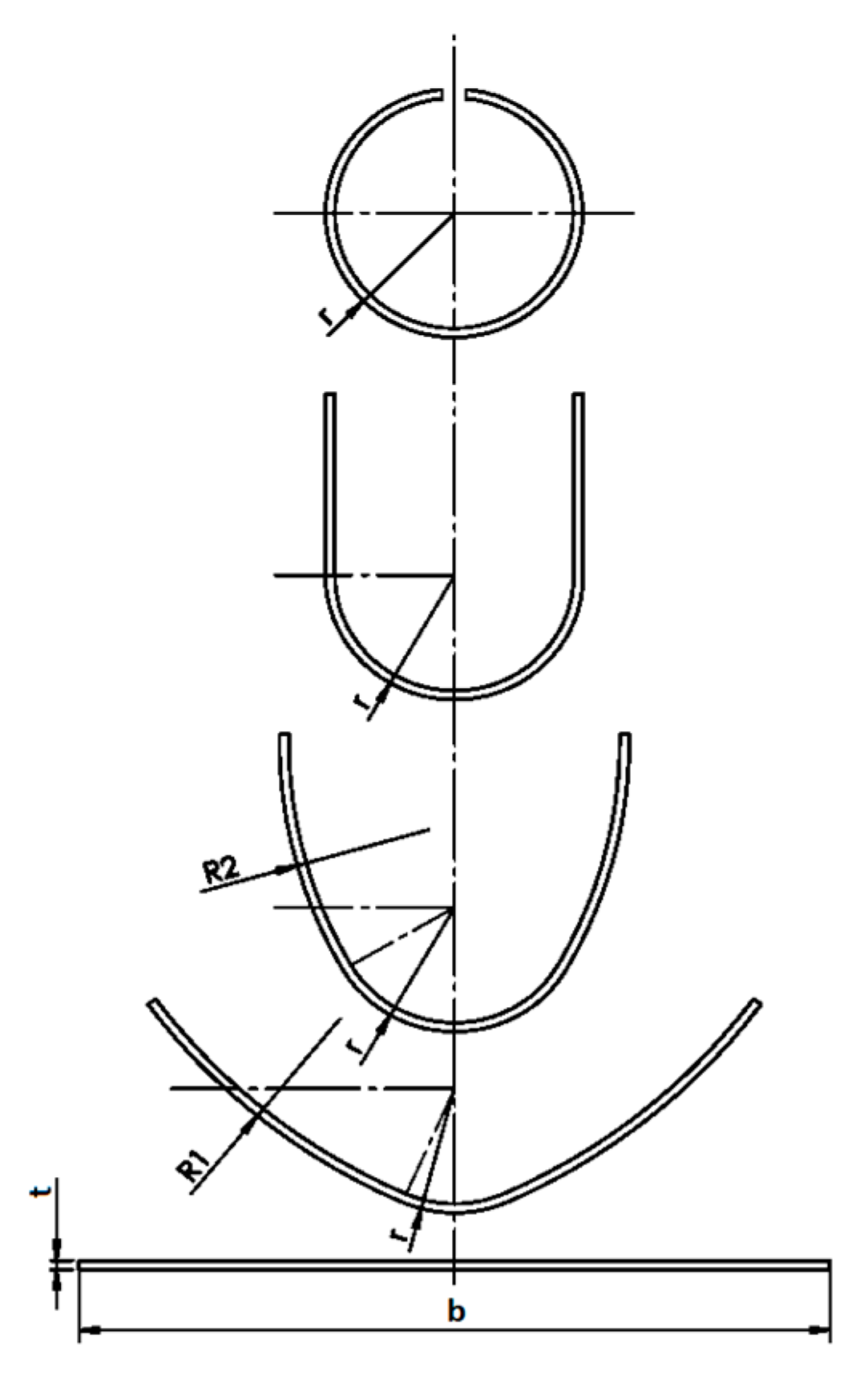
- Continuous bending of the seam tube;
- TIG welding with a risk of hard carbide precipitation.
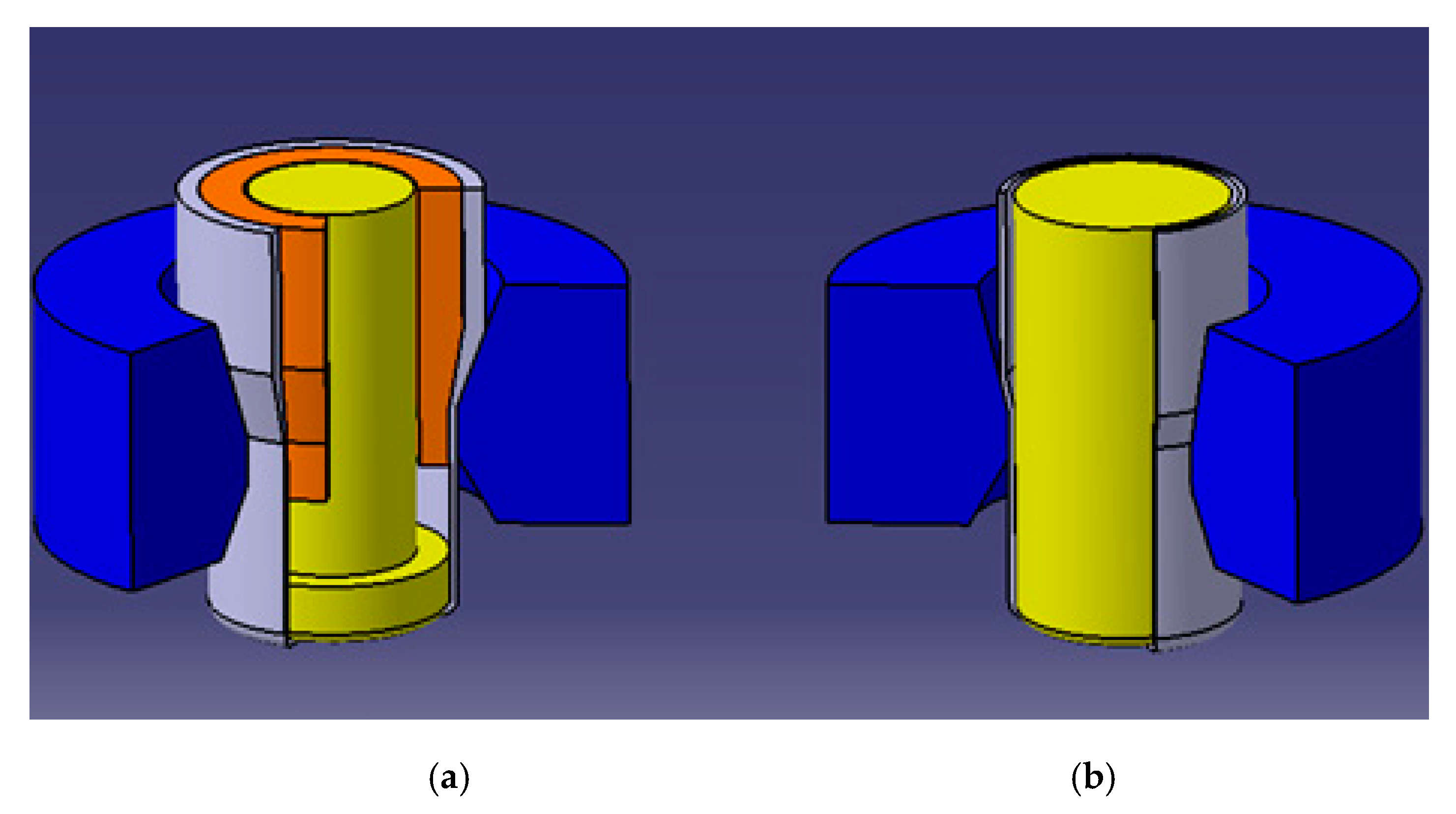
3.3. The Technological Process Modeling of Tube Drawing with Limited Dimensions
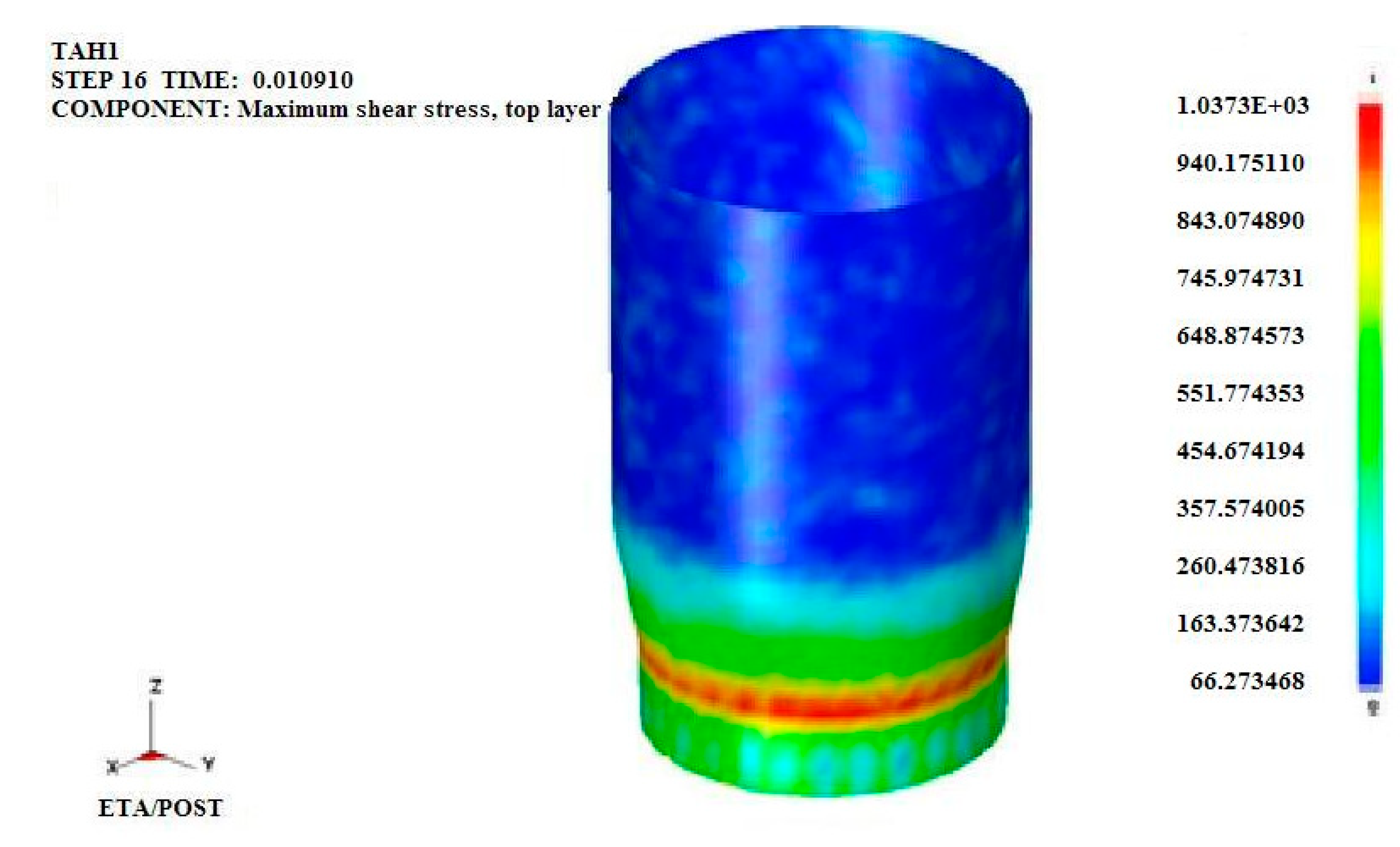
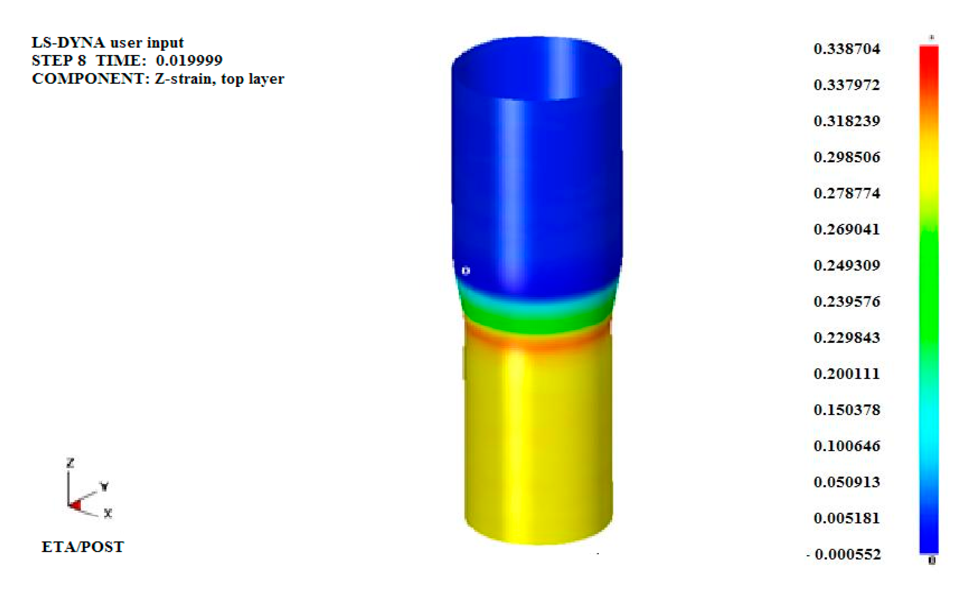
3.4. Results of Drawing Simulation of Tubes Drawing with Limited Dimensions
- STRAIN—drawing force determined through strain;
- STRESS—stress in a formed material;
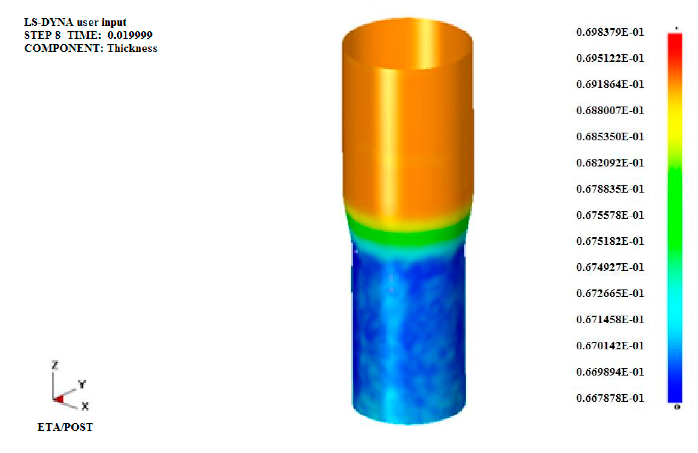
- THICKNESS—wall thickness of the tube.
3.4.1. The Values of the Simulation of Drawing Forces
- σp—true stress of the formed material at an appropriate true strain;
- Re—yield strength of the formed material;
- A—percentage elongation of the formed material;
- r—normal anisotropy of the formed material;
- φ—true strain during particular technological operations;
- ρ—density of the formed material;
- µ—coefficient of friction;
- v—drawing speed of the technological process,
- sn−1—wall thickness in front of the drawing die;
- sn—wall thickness behind the drawing die;
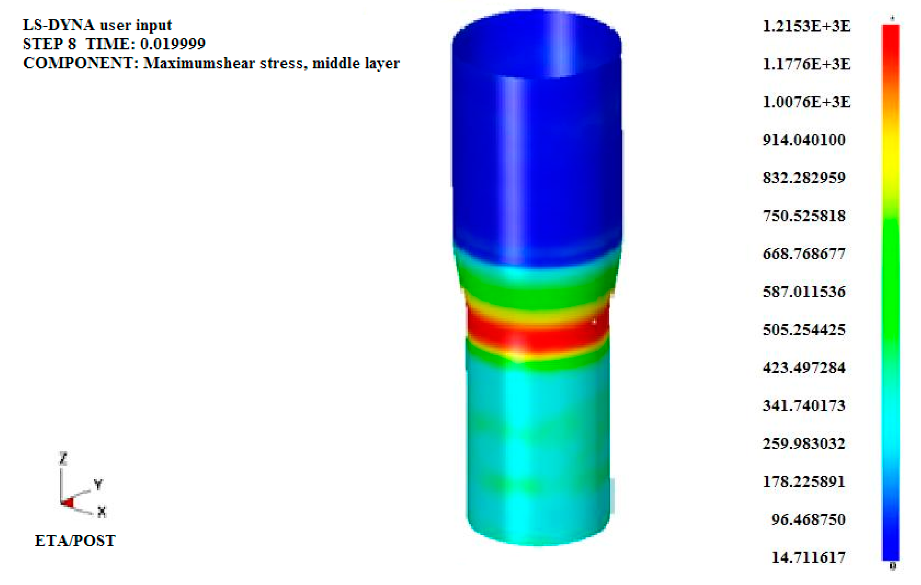
3.4.2. Boundary Conditions in the First Draw with Floating Mandrel
3.4.3. Boundary Conditions in the Third Draw without a Mandrel
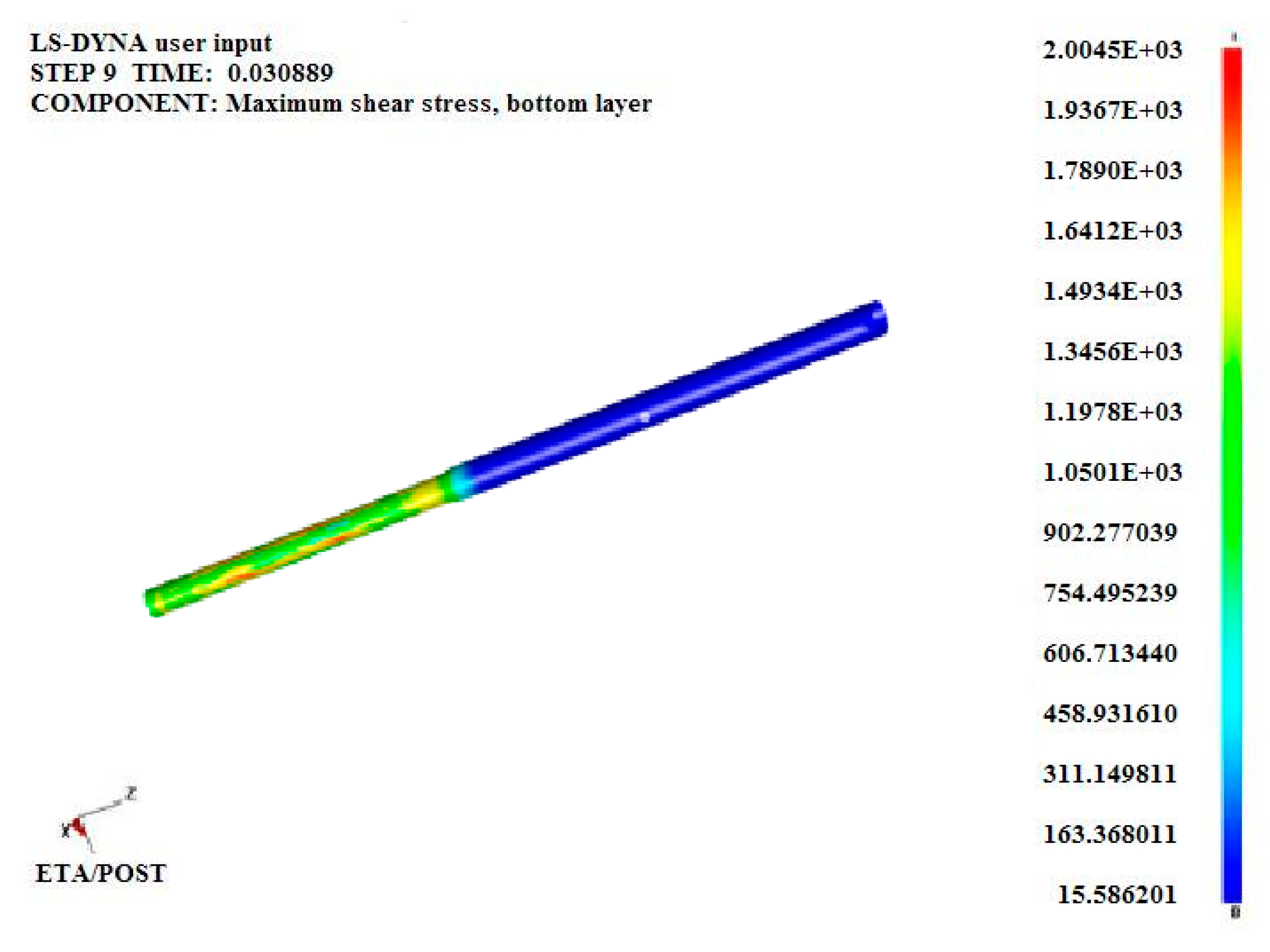
3.4.4. Boundary Conditions in the Eleventh Draw without a Mandrel
4. Discussion
5. Conclusions
Author Contributions
Funding
Acknowledgments
Conflicts of Interest
References
- Počta, B. Ocelové Trubky (in Czech) (Steel Tubes); 1. Part; SNTL: Prague, Czech Republic, 1963. [Google Scholar]
- Bramley, A.N.; Smith, D.J. Tube drawing with a floating plug. Met. Technol. 1976, 3, 322–331. [Google Scholar] [CrossRef]
- Świtkowski, K.; Hatalak, R. Study of the new floating-plug drawing process of thin-walled tubes. J. Mater. Process. Technol. 2004, 151, 105–114. [Google Scholar] [CrossRef]
- Pociecha, D.; Boryczko, B.; Osika, J.; Mroczkowski, M. Analysis of tube deformation process in a new pilger cold rolling process. Arch. Civ. Mech. Eng. 2014, 14, 376–382. [Google Scholar] [CrossRef]
- Storožev, M.; Popov, J. Grundlagen der Umformtechnik; Verlag Technik: Berlin, Germany, 1968. [Google Scholar]
- Hwang, Y.M.; Li, Z.S.; Lin, T.Y. Formability Discussion in Dieless Drawing of Stainless Steel Tubes. Key Eng. Mater. 2014, 626, 10–15. [Google Scholar] [CrossRef]
- Rubio, E.; Camacho, A.; Pérez, R.; Marín, M. Guidelines for Selecting Plugs Used in Thin-Walled Tube Drawing Processes of Metallic Alloys. Metals 2017, 7, 572. [Google Scholar] [CrossRef] [Green Version]
- Evin, E.; Tomáš, M.; Buriková, K.; Kepič, J. The Prediction of the Mechanical Properties for Dual-Phase High Strength Steel Grades Based on Microstructure Characteristics. Metals 2018, 8, 242. [Google Scholar] [CrossRef] [Green Version]
- Yoshida, K.; Yokomizo, D.; Komatsu, T. Production of Special Tubes with a Variety Cross-Sectional Shapes by Bunch Drawing and Fluid-Mandrel Drawing. Key Eng. Mater. 2014, 622, 731–738. [Google Scholar] [CrossRef]
- Hartl, C. Review on Advances in Metal Micro-Tube Forming. Metals 2019, 9, 542. [Google Scholar] [CrossRef] [Green Version]
- Atanasiu, N. Optimierung der technologischen Parameter beim Ziehen von Rohren auf fliegendem Dorn. Metalurgia 1980, 32, 454–464. [Google Scholar]
- Furushima, T.; Manabe, K. FE analysis of size efect on deformation and heat transfer behavior in microtube dieless drawing. J. Mater. Process. Technol. 2008, 201, 123–127. [Google Scholar] [CrossRef]
- Tang, D.; Fang, W.; Fan, X.; Li, D.; Peng, Y. Efect of die design in microchannel tube extrusion. Procedia Eng. 2014, 81, 628–633. [Google Scholar] [CrossRef] [Green Version]
- Pankin, W. Grundlagen der Herstellung zweiteiliger Dosen. Werkstatt Betrieb. 1977, 18, 26–27. [Google Scholar]
- Beneš, M.; Maroš, B. Křivky Přetvárných Odporů Ocelí (in Czech) (Flow Curves of Steels); SNTL: Prague, Czech Republic, 1986. [Google Scholar]
- Špecifikácia Materiálov (in Slovak) (Materials Specification); Non-Public Document 14 10 211.
- Orszagh, P.; Orszagh, V. (Zváranie TIG Ocelí a Neželezných Kovov) (in Slovak) (TIG Welding of Steels and Non-Ferrous Metals); SAV: Bratislava, Slovakia, 1998. [Google Scholar]
- Brick, M.; Pense, A.; Gordon, R. Structure and Properties of Engineering Materials, 4th ed.; McGraw-Hill: New York, NY, USA, 1977. [Google Scholar]
- Počta, B. Základy Teorie Tváření Kovů (in Czech) Theory Fundamentals of Metal Forming; SNTL: Prague, Czech Republic, 1966. [Google Scholar]
- Pernis, R.; Kasala, J. The influence of the die and floating plug geometry on the drawing process of tubing. Int. J. Adv. Manuf. Technol. 2012, 65, 1081–1089. [Google Scholar] [CrossRef]
- Danckert, J. The influence of the punch land in backward can extrusion. CIRP Ann. 2004, 53, 227–230. [Google Scholar] [CrossRef]
- Mojžiš, M.; Ridzoň, M.; Bílik, J.; Parilák, L. The stability of geometry by the production of the multi rifled tubes. In Proceedings of the 26th International Conference on Metallurgy and Materials METAL 2017, Ostrava, Czech Republic, 24–26 May 2017; pp. 351–356. [Google Scholar]
- Palengat, M.; Chagnon, G.; Favier, D.; Louche, H.; Linardon, C.; Plaideau, C. Cold drawing of 316L stainless steel thin-walled tubes: Experiments and finite element analysis. Int. J. Mech. Sci. 2013, 70, 69–78. [Google Scholar] [CrossRef] [Green Version]
- Tang, D.; Zhang, Q.; Li, D.; Peng, Y. A physical simulation of longitudinal seam welding in micro channel tube extrusion. J. Mater. Process. Technol. 2014, 214, 2777–2783. [Google Scholar] [CrossRef]
- Furushima, T.; Manabe, K. Experimental and numerical study on deformation behavior in dieless drawing process of superplastic microtubes. J. Mater. Process. Technol. 2007, 191, 59–63. [Google Scholar] [CrossRef]
- Danckert, J.; Endelt, B. LS-DYNA used to analyze the drawing of precision Tubes. In Proceedings of the 7th European LS-DYNA Conference, Salzburg, Austria, 14–15 May 2009. [Google Scholar]
- Boutenel, F.; Delhomme, M.; Velay, V.; Boman, R.O. Finite element modelling of cold drawing for high-precision tubes. Comptes Rendus Mécanique 2018, 346, 665–677. [Google Scholar] [CrossRef]


| Material | Chemical Composition wt % | ||||||
|---|---|---|---|---|---|---|---|
| EW | C 0.027 | Si 0.56 | Mn 1.07 | P 0.019 | S 0.001 | Cr 18.02 | Ni 10.05 |
| KT | C 0.012 | Si 0.52 | Mn 1.56 | P 0.022 | S 0.05 | Cr 18.25 | Ni 10.08 |
| σp (MPa) | Re (MPa) | μ (-) | v (m.min−1) | sn−1 (mm) | φ (-) | dn−1 (mm) | dn (mm) |
|---|---|---|---|---|---|---|---|
| 991 | 286 | 0.08 | 10 | 0.1 | 0.4387 | 3.25 | 2.88 |
| σp (MPa) | Re (MPa) | μ (-) | v (m.min−1) | sn−1 (mm) | φ (-) | dn−1 (mm) | dn (mm) |
|---|---|---|---|---|---|---|---|
| 1215 | 286 | 0.08 | 30 | 0.0634 | 0.1122 | 2.54 | 2.19 |
| σp (MPa) | Re (MPa) | μ (-) | v (m.min−1) | sn−1 (mm) | φ (-) | dn−1 (mm) | dn (mm) |
|---|---|---|---|---|---|---|---|
| 1947 | 286 | 0.08 | 65 | 0.0673 | 0.4604 | 0.408 | 0.342 |
| Draw | Calculated Values | Measured Values | Simulated Values Ft (N) | |||
|---|---|---|---|---|---|---|
| Ftmin (N) | Ftmean (N) | Ftmax (N) | Ftmin (N) | Ftmax (N) | ||
| 1st 2nd | 588 541 | 629 584 | 703 670 | 520 435 | 600 514 | 740 680 |
| 3rd 4th | 203 194 | 215 207 | 261 251 | 264 231 | 287 268 | 310 280 |
| 5th 6th | 182 176 | 191 187 | 229 209 | 215 193 | 249 229 | 235 210 |
| 7th 8th | 164 139 | 171 148 | 190 165 | 174 149 | 211 167 | 190 165 |
| 9th 10th | 111 87 | 117 99 | 130 114 | 130 109 | 155 115 | 130 120 |
| 11th | 77 | 85 | 108 | 85 | 93 | 90 |
| Draw | Calculated Values | Simulated Values σ (MPa) | ||
|---|---|---|---|---|
| σtmin (MPa) | σtmean (MPa) | σtmax (MPa) | ||
| 1st 2nd | 963 1201 | 991 1209 | 1325 1370 | 1037 1216 |
| 3rd 4th | 1183 1333 | 1215 1370 | 1577 1748 | 1215 1345 |
| 5th 6th | 1407 1579 | 1475 1598 | 1863 1993 | 1487 1626 |
| 7th 8th | 1621 1684 | 1647 1726 | 2046 2129 | 1487 1722 |
| 9th 10th | 1741 1833 | 1757 1875 | 2161 2286 | 1830 1843 |
| 11th | 1932 | 1947 | 2360 | 1936 |
| Draw | Measured Values | Simulated Values sn (mm) | |
|---|---|---|---|
| sntmin (mm) | sntmax (mm) | ||
| 1st 2nd | 0.0717 0.0581 | 0.0732 0.0634 | 0.0752 0.0685 |
| 3rd 4th | 0.0661 0.0593 | 0.0702 0.0637 | 0.0668 0.0653 |
| 5th 6th | 0.0605 0.0575 | 0.0714 0.0602 | 0.0650 0.0648 |
| 7th 8th | 0.0643 0.0696 | 0.0693 0.0811 | 0.0647 0.0642 |
| 9th 10th | 0.0720 0.0596 | 0.0785 0.0723 | 0.0640 0.0630 |
| 11th | 0.0540 | 0.0575 | 0.0635 |
© 2020 by the authors. Licensee MDPI, Basel, Switzerland. This article is an open access article distributed under the terms and conditions of the Creative Commons Attribution (CC BY) license (http://creativecommons.org/licenses/by/4.0/).
Share and Cite
Schrek, A.; Brusilová, A.; Švec, P.; Gábrišová, Z.; Moravec, J. Analysis of the Drawing Process of Small-Sized Seam Tubes. Metals 2020, 10, 709. https://doi.org/10.3390/met10060709
Schrek A, Brusilová A, Švec P, Gábrišová Z, Moravec J. Analysis of the Drawing Process of Small-Sized Seam Tubes. Metals. 2020; 10(6):709. https://doi.org/10.3390/met10060709
Chicago/Turabian StyleSchrek, Alexander, Alena Brusilová, Pavol Švec, Zuzana Gábrišová, and Ján Moravec. 2020. "Analysis of the Drawing Process of Small-Sized Seam Tubes" Metals 10, no. 6: 709. https://doi.org/10.3390/met10060709
APA StyleSchrek, A., Brusilová, A., Švec, P., Gábrišová, Z., & Moravec, J. (2020). Analysis of the Drawing Process of Small-Sized Seam Tubes. Metals, 10(6), 709. https://doi.org/10.3390/met10060709