Abstract
The paper presents the results of the microstructure investigation, phase and chemical composition, microhardness as well as corrosion and wear resistance tests of B-Si coatings produced on C45 steel. In this study, boron and silicon were added to the surface of steel using the laser alloying process. The main purpose of the study was to check whether the use of silicon, boron or a mixture of these chemical elements would improve the mechanical properties of the surface. Boron and silicon, as well as its mixture, were prepared in various proportions and subsequently were applied on steel substrate in the form of pre-coat (paste) of 80 µm thick. All pre-coats were processed by a laser beam and the obtained microstructures were analyzed and compared. Laser alloying processes were carried out using device equipped with a CO2 laser. After laser alloying, the microstructure consisted of a melted zone, heat affected zone and unchanged steel substrate. The newly created B-Si coatings were characterized by properties better than the case of boron and silicon coatings, with particularly high microhardness in the range from 1430 HV to 1870 HV, as well as high corrosion and wear resistance.
1. Introduction
Industries are constantly looking for modern processing technologies of metal alloys to increase their mechanical and operational properties. Currently, thermo-chemical treatments such as nitriding, carburizing or boriding are commonly used. However, one disadvantage of such processes is their duration and high energy consumption. Due to these facts, laser processing, which includes laser hardening [1,2,3,4], laser remelting [5,6,7,8] and laser alloying [9], as well as laser cladding [10,11,12,13,14,15], are playing an increasingly important role. Despite the fact that boronized layers produced by the diffusion method have many advantages, such as high microhardness, good adhesion of the needle-like structure to the substrate, as well as good wear and corrosion resistance, they have some disadvantages—in particular, brittleness and porosity in the surface zone [16,17,18]. These disadvantages are bound to occur and may contribute to the deterioration of operational properties in the final product. To improve the properties of such a layer, different methods of its modification are used. Currently, they mainly include laser modification, which involves melting the existing boronized layer [5,6,18]. As a result of this process, microstructure and properties of layers change. The process of introducing boron into the surface layer by laser alloying increases its properties [19,20]. As is known, boron is a chemical element that strongly increases hardenability. Therefore, its presence in surface layer may also cause cracks. However, by choosing the suitable parameters of laser processing and by introducing additional chemical elements, this problem may be solved. Laser alloying processes allow for the development of modern coatings with different microstructures (among other non-equilibrium) and chemical composition. They are possible through concomitant rapid remelting and solidification of modified surface. To modify the surface of metal alloys, many authors use boron and other chemical elements such as chromium, silicon, copper, nickel as well as the compounds and phases. In paper [10], the research was conducted on Fe-based amorphous/glassy layer deposition on a carbon steel by laser surface cladding. The aim of the study was to improve resistance of the substrate to wear and corrosion. In the research, the authors used three mixtures: 94Fe4B2C, 75Fe15B10Si and 78Fe10BC9Si2Al1C. Despite the rapidly quenching accompanying laser surface cladding, none of the coatings retained amorphous/glassy cladding, but it was found that the clad microstructure is characterized by fine phases in ferritic matrix. The authors found that microhardness, corrosion resistance and wear resistance showed a significant enhancement, particularly after laser cladding with 94Fe4B2C. Despite many difficulties, using air plasma spraying technology is still popular. Currently, such coatings are also modified with a laser beam. In paper [21], the silicon coatings were deposited using air plasma spraying technology. The obtained results showed that the surface of the silicon coating was almost covered by submicronic particles mainly composed of silicon oxide. In paper [9], the authors attempted to develop an iron silicide dispersed surface on mild steel substrate by laser surface alloying with silicon using a CO2 laser. The authors found that the microstructure of mild steel after the laser processing with silicon consists of uniformly dispersed iron silicide in the grain refined α-iron matrix with an improved microhardness. Additionally, surface remelting in nitrogen increased the microhardness due to the formation of iron nitrides in addition to the presence of silicides. The graphite coating used prior to remelting improved even more microhardness due to the presence of martensite along with nitrides and silicides. On the basis of the conducted research, the authors stated that a maximum enhancement in wear resistance was achieved when the remelting process was performed in a nitrogen environment with carbon deposition. In paper [11], the coating of the Ni-Cr-B-Si alloy was prepared on a low carbon steel substrate using a laser cladding process. The authors measured and analyzed both microstructure, hardness and flame erosion mechanisms. It was found that the coating consists mainly of γ-Ni solid solution, FeNi3/Ni33Si12 eutectic and CrB ceramic phase, and has a microhardness about seven times higher that of the substrate material. In paper [22], an alloyed Fe-Si intermetallic compound layer was prepared on the surface of 302 stainless steel via a nonelectrolytic molten salt silicon infiltration method at different holding times. The wear resistances of the substrate and siliconized layers were evaluated through microhardness, toughness, friction and wear testing. The results of the corrosion resistance study showed that siliconized layers exhibited better wear resistance and pitting resistance than the 302 substrates. The authors found that these enhancements were mainly due to the alloyed Fe-Si intermetallic compound formed on the surface of the siliconized layer. In paper [23], the microstructure, microhardness as well as ductility and toughness of the Ni + Cr + B4C coating produced using laser processing on the of AISI 1020 steel were investigated. A hard, non-acicular and uniform boride layer was the result of these studies. Laser borided specimens processed by using higher laser beam energy densities were characterized by better ductility and toughness in comparison to specimens processed with lower energy densities. In [24], the distribution of a saturating element in the zone of the laser siliconizing of steels was investigated. It was established that the silicon concentration reaches 17–20 at. % in the upper part of the siliconized layer and decreases to 3–5 at. % moving to the boundary of partial melting. The silicon-saturated surface layer consists of two structural zones: the zone of coarse α-solution dendrites oriented in the direction of heat removal, which is adjacent to the boundary of partial melting; and the overlying zone of fine dendrites without a preferred spatial orientation.
After the analysis of available papers, there is a lack of publications in the field of simultaneous laser boron and silicon alloying. In many papers, researchers describe the influence of individual elements (B and Si) on the substrate material. The borosiliconized processes were described only with reference to diffusion processes. Therefore, the purpose of this study is to determine the influence of silicon and boron on C45 steel. In this work, microstructure, phase composition, microhardness and wear and corrosion resistance were examined with reference to B, Si and B-Si coatings produced using laser processing.
2. Materials and Methods
2.1. Materials
The coatings were produced on ring-shaped specimens, where the outer diameter was 20 mm, the inner diameter 12 mm, and the sample height 12 mm (specimens for microstructure, microhardness and wear resistance tests). The coatings were produced on the entire outer surface of the ring. Specimens for corrosion resistance tests and for phase composition analysis, dimensions were 60 mm long, 12 mm wide and 4 mm high. The volume of all specimens was the same, which was important because of the heat dissipation from coating to steel substrate. In this study, C45 steel as the substrate material was applied. The chemical composition of this material was investigated using Solaris CCD PLUS optical emission spectroscope and presented in Table 1. The purity of silicon powder (Figure 1a) was equal to 99.95%, while the purity of amorphous boron powder (Figure 1b) was ≥ 95%, as given by the producer Sigma-Aldrich, St. Louis, MO, USA.

Table 1.
Chemical composition of steel used [wt. %].

Figure 1.
Morphology of powders used: (a) silicon particles; (b) boron particles.
2.2. Parameters of Conventional Heat Treatment and Laser Alloying
Before the applying of pre-coat containing selected chemical elements, specimens were heat treated in 1123 K and tempered at 843 K for 1 h. The purpose of the heat treatment was to prevent the false impression that the proposed coatings are much better than the substrate. Often, the properties of the coating are compared to the non-heat treated substrate, which makes their properties seem to be much better than they are. Pre-coats (pastes) were prepared with powders and adhesive material in the form water glass. The thickness of pre-coat was equal to 80 µm thick. The amount of powder was selected by weight, taking into account their density (B-2340 kg/m³, Si-2330 kg/m³). In contrast, water glass and distilled water were adjusted so that the applied pre-coat had adequate adhesion to the steel substrate, stayed on the specimen’s surface and did not move off it. Water glass was intended to consolidate the applied coating, and water was to provide adequate consistency. After the coating had dried, the water evaporated from pre-coat, while water glass as a binding binder did not play a significant role during laser processing. The next step was the laser processing of the previously applied pre-coat. These processes were carried out using laser device TLF 2600 Turbo CO2 of nominal power of 2.6 kW (TRUMPF, Ditzingen, Germany). The laser device cooperated with the conventional lathe TUM-35D1 (Famot, Pleszew, Poland). During the studies, the laser beam power was equal to 1.04 kW, and scanning speed of laser beam was equal to 2.88 m/min. Laser beam diameter was 2 mm, hence laser beam radiation density was equal to 33.12 kW/cm2. The power density was calculated taking into account the laser beam power and the laser beam diameter. The circular shape of the mode laser beam TEM01* was applied in this study. Laser tracks were placed on entire surface of specimens, and distance between each other was equal to f = 0.5 mm. This resulted in the 75% parameter of overlapping. The distance between focusing mirror and the surface of pre-coat was 106.8 mm. The coatings production was composed of three steps. Firstly, the conventional vacuum heat treatment of substrate. Next, the application of pre-coat, and finally laser alloying of pre-coat with steel substrate. Figure 2 shows the scheme of coating production using laser device and lathe. In the same Figure schematic representation of the investigated specimen and its cross section is shown.
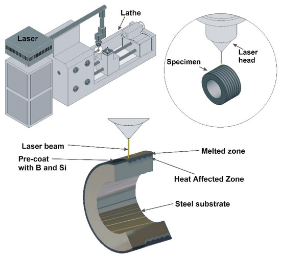
Figure 2.
Scheme of the coating production process and schematic representation of the investigated specimen.
2.3. Microstructure Observation, Chemical Composition and XRD Analysis
Microstructure observations were carried out on polished and etched cross-sections of specimens by using VEGA 5135 scanning electron microscope from (TESCAN, Brno, Czech Republic) and using optical microscope HRM-300 (Huvitz, Gunpo, Republic of Korea). In the first step, the specimens were grinded on water grinding abrasive paper with grit 120 to 2000 and then polished in diamond suspension for 20 min and finally using suspension of aluminum oxide during 10 min. In order to reveal microstructure, the specimens were etched in 2% HNO3 solution. The phase analysis of B, Si, and B-Si coatings were performed on EMPYREAN X-Ray diffractometer (PANalytical, Malvern, UK) using CuKα radiation in the angle range of 20° to 90°. This device is equipped with focal point (0.4 mm × 12 mm) and Kβ Ni radiation filter. In this study 45 kV and 40 mA were applied. The temperature during tests was equal to 25° C. In this study goniometer (Theta/Theta) and minimum step size 2Theta equal to 0.0001 s were applied. Chemical compositions of produced coatings were investigated using Ultim® Max energy dispersive spectrometry (EDS) (Oxford Instruments, High Wycombe, UK). The results were presented in the form of point analysis.
2.4. Microhardness Tests
To determine microhardness profiles a ZWICK 3212 B Vickers microhardness tester (Zwick, Ulm, Germany) was used. The parameters of measurements was as follows: indentation load of 100 G and loading time 15 s. All obtained coatings were investigated from the surface to the substrate, both in axis of laser tracks and on their overlaping zones.
2.5. Wear Resistance Tests
Wear resistance was examined using Amsler method, and as counterspecimen the S20S sintered carbide plate was applied. The composition of this type of sintered carbide is as follows: 58 wt. % of WC, 31.5 wt. % of (TiC + TaC + NbC), 10.5 wt. % of Co. Its hardness was equal to 1430 HV. Wear resistance tests were carried out under the load of 98 N and specimen speed equaled to 0.26 m/s, in dry friction conditions. Specimen mass loss (Δm) within a time unit was investigated. Five attempts of wear tests were performed for each of the analyzed coatings. Average values of mass loss were used to make the chart. The surface condition after the wear tests was observed using EZ4 W stereomicroscope (Leica, Wetzlar, Germany).
2.6. Corrosion Resistance Tests
The corrosion resistance of the coatings was measured by the potentiodynamic method using a 5% NaCl aqueous solution. The investigations were carried out using ATLAS 1131 potentiostat-galvanostat (Atlas-Sollich, Rębiechowo, Poland) in the range of −1.1V to −0.6V. The reference electrode was a saturated calomel electrode and the auxiliary electrode was a platinum electrode. The corrosion resistance of the specimens was estimated from anodic polarization curves recorded at an advance ratio of 0.5 mV·s−1 (scanning speed). The corrosion resistances of B-Si coatings were compared with siliconized and borided coatings. The potentiodynamic measurements were performed at a temperature of 295 K. Before corrosion resistant tests, the specimens were polished to obtain the same surface roughness and were cleaned using alcohol.
3. Results and Discussion
3.1. Microstructure and Phase Analysis
Microstructure images of the produced coatings were shown respectively in Figure 3 (Si), Figure 4 (B), Figure 5 (50% B-50% Si) and Figure 6 (20% B-80% Si). In the cross-section of each obtained coating, the microstructure was composed of a melted zone (MZ), a heat affected zone (HAZ) and a substrate. In the case of Si coatings, there is no visible boundary between the bottom part of the heat affected zone and the substrate. A slight grain growth is visible in the upper part of the heat affected zone, directly at the border with the melting zone. The most likely explanation for this is that the heat of the laser beam first was accumulated in the melted zone, and next was transferred to the thin layer of the substrate and caused grain growth in the heat affected zone. The difference between the core and heat affected zone was not clearly visible due to fact that specimens were subjected to heat treatment (quenching and tempering) and the sorbite microstructure was obtained in the substrate material. The laser beam created both the melting zone and the hardening of heat affected zone. Thus, the microstructure of the substrate after laser alloying was very similar to the state before this processing.
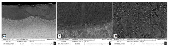
Figure 3.
Microstructure of Si coatings after laser alloying: (a) laser tracks; (b) boundary between the melted zone (MZ) and the heat affected zone (HAZ); (c) magnification of selected area in the MZ.
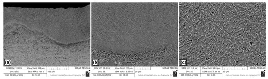
Figure 4.
Microstructure of boron coating produced using laser alloying: (a) laser tracks; (b) boundary between the MZ and HAZ; (c) magnification of selected area in the MZ.
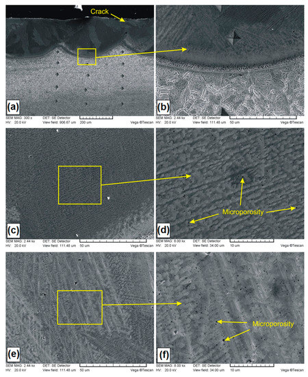
Figure 5.
Microstructure of B-Si coating containing 50% boron and 50% silicon in pre-coat: (a) general view of laser tracks; (b) boundary between the MZ and HAZ; (c) dark area of the MZ; (d) magnification of dark area; (e) light area of the MZ; (f) magnification of light area.
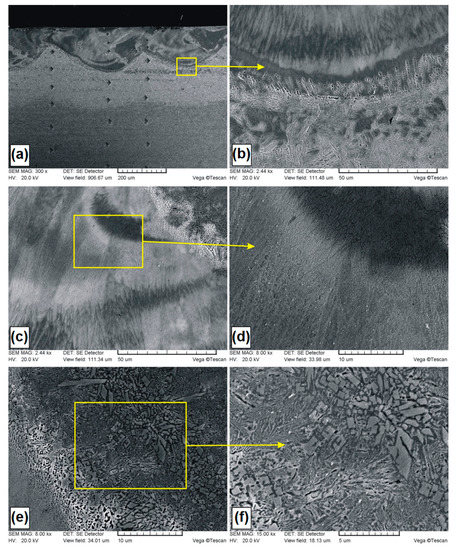
Figure 6.
Microstructure of B-Si coating containing 20% boron and 80% silicon in pre-coat: (a) general view of laser tracks; (b) boundary between the MZ and HAZ; (c) central are area of the MZ; (d) magnification of central area; (e) crystals in the MZ; (f) magnification of crystals.
Figure 3a shows the Si coating. Several overlapping laser tracks are visible. Characteristic of laser processing are parabolic remelting lines. In this study, they are associated with the use of a CO2 laser that has a power density distribution similar to the Gaussian distribution. Figure 3b showed magnification of the boundary zone between the melted zone and the heat affected zone. The grains in the melted zone were relatively large, and had a longitudinal and rounded shape. Near the steel substrate, where heat was discharged faster, the grain size was smaller. Figure 3c presents a magnification of melted zone for half the thickness of Si coating. It was found that the microstructure is composed of the grains of a silicon solid solution in iron. The average thickness of the melted zone in the track axis was equal to 205 μm, while in the overlap zone it was equal to 147 μm. The obtained microstructure on the coating cross-section was different than in paper [24], where the applied laser processing parameters contributed to the formation of thinner coatings with microstructures of the globular solution α dendrites.
In Figure 4a, a general microstructure is shown after laser alloying with the boron pre-coat. The same laser beam parameters as for the other coatings were applied. Figure 4b shows the interface between the melted zone and the heat affected zone. In the melted zone (Figure 4c), boride–martensitic eutectics with a fine dendritic microstructure was observed. Authors of papers [19,25] observed similar eutectic microstructure. Dendrites growth and direction took place depending on the solidification rate (Figure 4b). The average thickness of the melted zone in the track axis was equal to 173 μm, while in the overlap zone it was 98 μm. The boundary between heat affected zone and melted zone was clearly visible due to presence of a flat solidification front.
On the subsurface zone of boron coating in some places small cracks or microcracks were observed. This is often observed in surface layers and coatings containing boron. This is due to the increase in hardness and compressive stresses occurring during solidification of the melted zone. Cracks extending from the top surface in the coating containing boron and silicon were observed also in this paper [11]. These cracks were caused by the residual stress. The authors found that this phenomena mainly originates from the contraction during the cooling process and the mismatch in coefficients of thermal expansion between coating and substrate, resulting in the crack formation.
In Figure 5a–f, microstructures of B-Si coatings containing of 50% boron and 50% silicon in pre-coat are presented. The general view of the microstructure was presented in Figure 5a. A few cracks from the surface towards the melted zone were observed. In the melted zone, no larger porosities were presented. It was found that the deep remelting of coating contributes to the formation of very good metallurgical bonding to the steel substrate. The average thickness of the melted zone in the track axis was equal to 242 μm, while in the overlap zone it was 164 μm. The difference between the heat affected zone and the steel substrate was observed. Sorbite in the steel substrate remains darker after etching. In Figure 5b, the magnification of the boundary area between the melted zone and heat affected zone is shown. The solidification front caused dendrite growth in the direction from substrate to surface, forming a narrow dendrite zone along the entire remelting line of tracks. The steel substrate became the nucleation place for dendrites and the process of solidification of the coating began there. Above the narrow dendrite zone, solidification proceeded in a less predictable manner and was dependent on the convective movements in the liquid lake, which was associated with the laser beam action. Convective movements, which caused changes in dendrite nucleation, took place in various places along the entire thickness of the coating.
This was shown in Figure 5a, where the presence of light and dark areas was found. The magnification of the dark zone is shown in Figure 5c, while the light zone is shown in Figure 5e. Microstructure details are shown in sequence in Figure 5d–f, and analyzed areas were indicated in rectangular frames. Figure 5c shows the microstructure, where mainly columnar dendritic grains with areas of small cellular grains were found, while in Figure 5e, dendrites of first and second type are shown. Single microporosities, not exceeding 25 μm, were identified among dendrites. By enlarging the selected area (Figure 5d,f), it was found that the quantity of the occurring microporosity was much greater and covered the entire study area. The size of these microporosities did not exceed 4 μm. The occurrence of microporosities does not have to be negatively perceived in the aspect of practical application.
In Figure 6a–f, microstructures of B-Si coatings containing of 20% boron and 80% silicon in pre-coat are presented. The general view of the microstructure is presented in Figure 6a. The average thickness of the melted zone in the track axis was equal to 182 μm, while in the overlap zone, it was 98 μm. In the produced B-Si coating (20% B and 80% Si), no cracks and no porosity was found. However, it was found that the melted zone was etched nonuniformly in some areas. This can indicate considerable dendrite segregation under the rapid crystallization conditions. In paper [23], it was found that the phenomenon of dendrite segregation during the melting of the surface by laser beam causes an increase in concentration of alloying elements in the liquid phase.
In Figure 6b, the boundary between the melted zone and heat affected zone is presented. In the melted zone, a dendritic microstructure that grows from the steel substrate towards the surface was observed. In the heat affected zone, martensite needles were identified. It was found that the composition of pre-coat had influence on the morphology of martensite. Martensite needles in B-Si coating consisting of 20% B and 80% Si were slightly larger than in the B-Si coating with a greater amount of boron. In the central part of the melted zone (Figure 6c,d), dendritic microstructures with very small dendritic cells as well as crystal occurrence areas were found. Comparing both B-Si coatings, it was found that a larger amount of silicon in the melted zone (which resulted from the higher silicon content in the pre-coat) had influence on the size of dendritic cells. An example of the crystal occurrence area is shown in Figure 6e,f. The size of secondary crystals did not exceed 4 μm, and in the overwhelming majority, these crystals were much smaller than 1 μm. During observations at high magnifications of all areas in the melted zone, no microcracks and no microporosity were found. Thus, it was found that the increase in silicon content and decrease in boron content caused the removal of the porosity from coating.
The phase composition of all produced coatings was analyzed and the results were shown in Figure 7. Outstanding iron peaks were identified for all specimens. This indicated a good mixing of pre-coats with the steel substrate. The thickness of pre-coats was equal to 80 μm, but the obtained coatings were much thicker, hence the large share of iron.
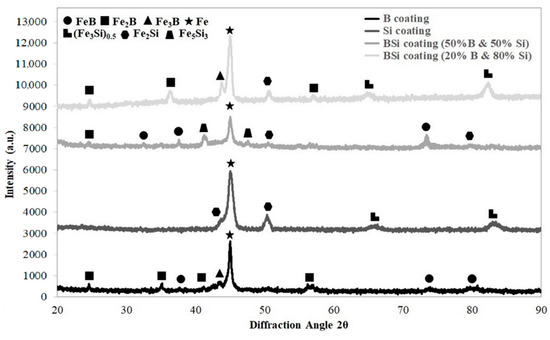
Figure 7.
XRD spectrum for coatings produced using laser processing and pre-coat containing boron, silicon and the mixtures of B-Si.
In the case of coatings produced by laser alloying of the boron pre-coat, boride phases were identified. They were equilibrium iron borides FeB and Fe2B as well as nonequilibrium iron boride Fe3B. In Si coatings, peaks from silicides Fe2Si and (Fe3Si)0.5 were identified. In the B-Si coating containing 80% silicon, peaks from phases (Fe3Si)0.5 and Fe2Si were identified. However, in the B-Si coating containing 50% silicon, mainly Fe5Si3 phase was visible. In the B-Si coating with higher boron content, FeB and Fe2B phases were found, while in the lower boron content, Fe2B and Fe3B phases were detected. Other silicon phases were not clearly identified. Laser processing is characterized by the fact that the solubility of chemical elements in the molten pool are different. All laser processing parameters had influence both on microstructure in the melted zone and on changes in the amount of silicon and boron in the coatings.
3.2. EDS Analysis Results
Analyzed B, Si and B-Si coatings are shown in Figure 8. Measurement points of significant chemical elements occurring in the produced coatings were marked with crosses. The obtained results are shown in Table 2. Figure 8a shows the EDS measurement point for B-coating. The boron content ranged from 9.8 wt. % to 15.0 wt. %, which corresponded to the iron boron phases identified in result of XRD tests (Figure 7). Individual boron contents can be assigned to the phases Fe2B and Fe3B (about 10 wt. % B) as well as FeB (about 15 wt. % B). The boron content decreased gradually from the surface to the substrate. Due to the fact that boron is a light element, the EDS results are only approximate. In the heat affected zone, no boron was found. Figure 8b shows the results for the Si coating. Similar to the case of boron coating, the measuring points were distributed throughout the entire laser tracks. In silicon etched areas, an increased silicon content was found. XRD tests detected silica phases, but the obtained silicon values are not so high, which may indicate that a silicon-saturated iron phase was formed at the analyzed points. Figure 8c shows a B-Si coating containing 20% boron and 80% silicon. Silicon content in the light areas is smaller than in dark areas. Figure 8d shows a B-Si coating containing 50% boron and 50% silicon. In the analyzed B-Si coating, it can be seen that in areas with increased boron content, the percentage of silicon is smaller. It can be presumed that in the microstructure of the melted zone, complex phases are also formed, in addition to the phases confirmed by XRD studies [26,27]. The silicas and borides formed in the coating have an influence on the properties. Silicas increase the corrosion resistance by forming a thin passivation film [28,29], whereas borides have a positive effect on microhardness and wear resistance [16,18].
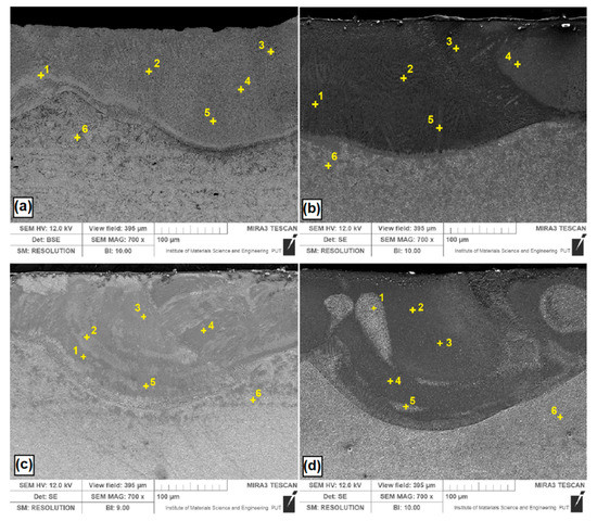
Figure 8.
Energy dispersive spectrometry (EDS) point of coatings after laser alloying with: (a) boron; (b) silicon; (c) B-Si containing 20% boron and 80% silicon; (d) B-Si containing 50% boron and 50% silicon.
Table 2.
Chemical composition of B, Si and B-Si coatings.
3.3. Microhardness Profiles
Microhardness was investigated both in tracks axis and on their overlapping. In both cases, the results were very similar. Therefore, for a clear presentation of results, in Figure 9, only microhardness profiles made in the laser tracks axis are presented. All charts were put together for comparison. The maximum microhardness of the boron coating was equal to 1700 HV0.1, and the decrease in hardness was slight over the entire thickness of the melted zone. This hardness value is slightly smaller than the microhardness of the diffusion boronized layer. The minimum microhardness in the melted zone was equal to 1640 HV0.1 and corresponded to the hardness of Fe2B iron boride. The most important advantage of the obtained coating in comparison to diffusion boronized layer was its thickness, significantly exceeding the one obtained in the diffusion process. The microhardness of Si coatings in the melted zone was about 800 HV0.1 and slightly decreased towards the substrate. Consequently, the lowest microhardness was obtained for Si coating. In accordance with the Fe-Si equilibrium diagram, no hard phases are formed, only a solid solution of silicon in Feα. For comparison, in paper [24], the authors found that the more silicon-saturated upper regions are characterized by a microhardness of ~8.8 GPa, whereas in regions adjacent to the melting boundary, the microhardness drops to a value of ~5 GPa. However, they used other laser parameters in their research, which could undoubtedly have an impact on differences in the obtained results. Analyzing the remaining results, it can be concluded that boron concentration had an influence on microhardness of B-Si coatings. The addition of 20% boron to Si coating caused almost double increase the microhardness.
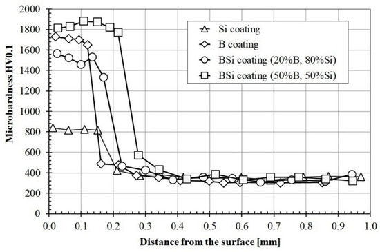
Figure 9.
Microhardness profiles of coatings produced using laser processing and pre-coat containing boron, silicon and the B-Si mixture in various proportions.
The B-Si coating containing 50% boron was characterized by the highest microhardness, which reached the value of approximately 1870 HV0.1. Such microhardness was observed over the entire thickness of the melted zone. Reducing the boron content to 20% in the pre-coat caused a significant reduction in microhardness and its heterogeneity in the melting zone of the coating. The microhardness of the B-Si coating containing 20% boron ranged from 1430 HV0.1 to 1580 HV0.1. The microhardness of all coatings rapidly decreased in the heat affected zone. In all cases except the B-Si coating containing 50% boron, the microhardness in this zone was around 400 HV0.1 (576 HV0.1 for B-Si coating containing 50% boron). The substrate microhardness was 350 HV0.1 and corresponded to sorbite.
3.4. Wear Resistance
Figure 10 shows wear resistance of all studied coatings compared with C45 steel subjected heat treatment. The graphs show the mass loss of specimens over time. It can be seen that materials without applied coating had the largest mass loss. Coatings produced by laser processing of pre-coats containing boron and silicon or B-Si mixture were characterized by increases in wear resistance. The silicon coating was characterized by the highest wear intensity among the tested specimens after laser processing. It was associated with the lowest microhardness of Si coating. The specimen during the wear test was initially characterized by a smaller mass loss, after about two hours, the mass loss increased. This was due to the greater amount of iron in the area below the melted zone. This iron came from a steel substrate. The B-Si coating containing 50% B and 50% Si was characterized by the highest wear resistance. A correlation between the obtained microhardness and wear resistance was found. Therefore, it can be concluded that additional content of boron in B-Si coating improves wear resistance.
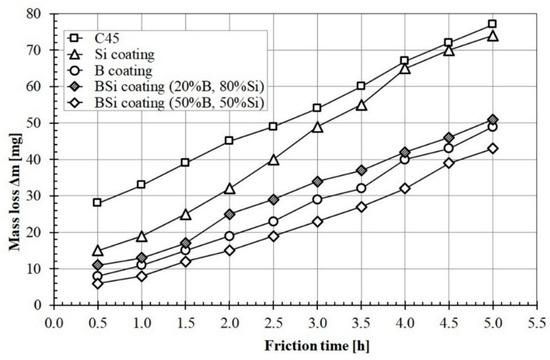
Figure 10.
Wear resistance of studied B, Si and B-Si coatings.
In Figure 11, examples of the surface condition after wear resistance tests are shown. The wear of C45 steel specimens without coating was characterized by typical abrasion mechanisms such as surface scratching and microcutting (Figure 11a). The same wear mechanisms occurred in the case of specimens with coatings characterized by high microhardness and boron content (B coating and B-Si coating containing 50% B) which were shown in Figure 11c,e respectively. It should be noted that there were many visible cracks in the coating produced using pre-coating with only boron. The cracks also appear in B-Si coating containing 50% B, but to a much lesser extent.
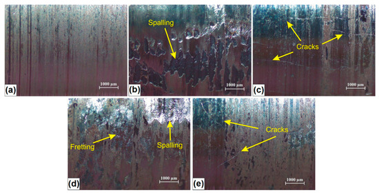
Figure 11.
Surface condition of studied specimens after wear resistance test: (a) C45 steel; (b) Si coating; (c) B coating; (d) B-Si coatings with 80% Si; (e) B-Si coatings with 50% Si.
Despite the cracks, it was observed that B-Si coating (50% B) has the highest wear resistance. In the case of coatings containing a greater amount of silicon (Si coating and B-Si coating containing 80% Si), it was found that the basic wear mechanisms were scratching, fretting and spalling. The spalling mechanism relies on the material loss, as a result of the propagation of microcracks initiated inside the coating. This is due to the cyclic interaction of contact stresses and the penetration of these microcracks to the surface. These microcracks probably arose during the wear test, because in microstructure of the melted zone, no cracks were identified.
3.5. Corrosion Resistance
The results of the corrosion resistance tests conducted on produced coatings were presented in Figure 12. Both the potential and current of corrosion were analyzed. The potential range from −1.1 V to −0.6 V was applied. A lot of important information about the corrosion process is provided by cathode and anode polarization curves recorded ± 0.25 V around the corrosion potential, so the range used in this study was considered sufficient because it included all curves.
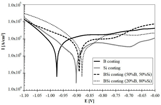
Figure 12.
Corrosion resistance of studied B, Si and B-Si coatings.
Corrosion current (Icorr) and corrosion potential (Ecorr) values were determined by extrapolating Tafel curves. The AtlasLab computer program from Atlas-Sollich was used for to read the values. Below the corrosion potential of Ecor, the metal has corrosion resistance. Above this potential, the oxidation process begins. Therefore, the material whose curve is shifted to the right has the best corrosion resistance among all specimens. The measurement results were presented in Table 3. Based on these studies, it was found that boron coating had lower corrosion resistance than coatings containing silicon. Boronized layers are most often resistant to corrosion, especially those with single-phase microstructure. Unfortunately, laser processing causes the formation of many phases, which is confirmed in the results of XRD tests. Multiphase microstructures have less corrosion resistance. The corrosion studies show that the laser processing of steel substrate with only silicon pre-coat improves the corrosion resistance compared to coatings produced using boron pre-coat.
Table 3.
Corrosion resistance parameters of B, Si and B-Si coatings.
The combination of two elements, boron and silicon, and the production of a pre-coating from them seems to be a good solution.
Laser processed B-Si coatings obtained greater resistance than B and Si coatings. Among all the coatings, the best corrosion resistance had B-Si coating containing 20% B and 80% Si. Based on microscopic observations, it was found that the cause of poorer corrosion resistance of B-Si coatings containing 50% B and 50% Si could be microporosities occurring in the melted zone. On the other hand, the authors of paper [10] found that the coating containing the Fe-B-C mixture has better corrosion resistance compared to the coating containing the Fe-B-Si.
4. Conclusions
Based on the conducted study, it was found that it is possible to modify C45 steel by laser processing and pre-coats consisting of boron and silicon. Basic material tests were carried out and presented in this paper. It was found that B-Si coatings combine the advantages of B and Si coatings. Through this combination, coatings with high microhardness, high corrosion resistance and relatively good wear resistance were obtained. It was found that the microstructure of coatings has decisive influence on the obtained properties. The B-Si coatings containing 50% B and 50% Si have good mechanical properties, such as a microhardness higher than 1800 HV and the highest wear resistance. The microstructure of this layer had microporosity in which lubricant may accumulate. The use of different types of lubricants that fill the microporosity can contribute to an even greater wear resistance. However, these microporosities reduce the corrosion resistance. In the case of B-Si coatings containing 20% B and 80% Si, the corrosion resistance is higher, but the other mechanical parameters decrease. In conclusion, B-Si coatings can be used in products requiring wear resistance and in order to increase the corrosion resistance. However, the composition of pre-coats subjected to laser processing should be properly selected. The chemical and phase composition have influence on the coating properties. The borides increase the microhardness and wear resistance, whereas silicas increase the corrosion resistance.
Author Contributions
Conceptualization, A.B., D.B.; methodology, A.B., D.B.; investigation, A.B., D.B., D.P. and M.P.; writing—original draft preparation, A.B., D.B.; writing—review and editing, D.B.; visualization, D.B. All authors have read and agreed to the published version of the manuscript.
Funding
The presented research results, were funded with grants for education allocated by the Ministry of Science and Higher Education in Poland.
Conflicts of Interest
The authors declare no conflict of interest.
References
- Steen, W.M. Laser material processing—An overview. J. Opt. A Pure Appl. Opt. 2003, 5, S3–S7. [Google Scholar] [CrossRef]
- Nath, A.; Sarkar, S. Laser Transformation Hardening of Steel. In Advances in Laser Materials Processing, 2nd ed.; Woodhead Publishing: Sawston, UK; Cambridge, UK, 2018; Chapter 11; pp. 257–298. [Google Scholar]
- Moradi, M.; Arabi, H.; Moghadam, M.K.; Benyounis, K.Y. Enhancement of surface hardness and metallurgical properties of AISI 410 by laser hardening process; diode and Nd:YAG lasers. Optik 2019, 188, 277–286. [Google Scholar] [CrossRef]
- Moradi, M.; Ghorbani, D.; Moghadam, M.K.; Kazazi, M.; Rouzbahani, F.; Karazi, S. Nd:YAG laser hardening of AISI 410 stainless steel: Microstructural evaluation, mechanical properties, and corrosion behavior. J. Alloy. Compd. 2019, 795, 213–222. [Google Scholar] [CrossRef]
- Bartkowska, A.; Swadźba, R.; Popławski, M.; Bartkowski, D. Microstructure, microhardness, phase analysis and chemical composition of laser remelted FeB-Fe2B surface layers produced on Vanadis-6 steel. Opt. Laser Technol. 2016, 86, 115–125. [Google Scholar] [CrossRef]
- Bartkowska, A.; Jurči, P.; Hudáková, M.; Bartkowski, D.; Kusý, M.; Przestacki, D. Effect of Diode Laser Beam Fluence on Change in Microstructure, Microhardness and Phase Composition of FeB-Fe2B Layers Produced on Vanadis-6 Steel. Arch. Metall. Mater. 2018, 63, 791–800. [Google Scholar] [CrossRef]
- Wang, Q.-Y.; Xi, Y.-C.; Zhao, Y.-H.; Liu, S.; Bai, S.-L.; Liu, Z.-D. Effects of laser re-melting and annealing on microstructure, mechanical property and corrosion resistance of Fe-based amorphous/crystalline composite coating. Mater. Charact. 2017, 127, 239–247. [Google Scholar] [CrossRef]
- Karmakar, D.P.; Gopinath, M.; Nath, A.K. Effect of tempering on laser remelted AISI H13 tool steel. Surf. Coat. Technol. 2019, 361, 136–149. [Google Scholar] [CrossRef]
- Majumdar, J.D. Development of In-Situ composite surface on mild steel by laser surface alloying with silicon and its remelting. Surf. Coat. Technol. 2010, 205, 1820–1825. [Google Scholar] [CrossRef]
- Manna, I.; Majumdar, J.D.; Chandra, B.R.; Nayak, S.; Dahotre, N.B. Laser surface cladding of Fe–B–C, Fe–B–Si and Fe–BC–Si–Al–C on plain carbon steel. Surf. Coat. Technol. 2006, 201, 434–440. [Google Scholar] [CrossRef]
- Xuan, H.-F.; Wang, Q.-Y.; Bai, S.-L.; Liu, Z.-D.; Sun, H.-G.; Yan, P.-C. A study on microstructure and flame erosion mechanism of a graded Ni–Cr–B–Si coating prepared by laser cladding. Surf. Coat. Technol. 2014, 244, 203–209. [Google Scholar] [CrossRef]
- Bartkowski, D.; Młynarczak, A.; Piasecki, A.; Dudziak, B.; Gościański, M.; Bartkowska, A. Microstructure, microhardness and corrosion resistance of Stellite-6 coatings reinforced with WC particles using laser cladding. Opt. Laser Technol. 2015, 68, 191–201. [Google Scholar] [CrossRef]
- Da Sun, S.; Fabijanic, D.; Ghaderi, A.; Leary, M.; Toton, J.; Sun, S.; Brandt, M.; Easton, M. Microstructure and hardness characterisation of laser coatings produced with a mixture of AISI 420 stainless steel and Fe-C-Cr-Nb-B-Mo steel alloy powders. Surf. Coat. Technol. 2016, 296, 76–87. [Google Scholar] [CrossRef]
- Ibrahim, M.Z.; Sarhan, A.A.; Kuo, T.Y.; Yusuf, F.; Hamdi, M.; Chien, C.S. Investigate the effects of the substrate surface roughness on the geometry, phase transformation, and hardness of laser-cladded Fe-based metallic glass coating. Int. J. Adv. Manuf. Technol. 2018, 98, 1977–1987. [Google Scholar] [CrossRef]
- Liu, X.; Ma, B.-B.; Hu, L.-W.; Li, J.; Qu, F.-S.; Le, G.; Li, X.-Y. Fe–Si–Al Coatings with Stable Wear Resistance Prepared by Laser Cladding Industrial Wastes. Metals 2019, 9, 96. [Google Scholar] [CrossRef]
- Krukovich, M.G.; A Prusakov, B.; Sizov, I.G. Plasticity of Boronized Layers; Springer: Berlin/Heidelberg, Germany, 2016; Volume 237, Available online: https://link.springer.com/book/10.1007/978-3-319-40012-9 (accessed on 10 May 2020)ISBN 978-3-319-40012-9. (eBook).
- Erdogan, A. Investigation of high temperature dry sliding behavior of borided H13 hot work tool steel with nanoboron powder. Surf. Coat. Technol. 2019, 357, 886–895. [Google Scholar] [CrossRef]
- Kulka, M. Current Trends in Boriding; Springer: Berlin/Heidelberg, Germany, 2019; Available online: https://www.springer.com/gp/book/9783030067816 (accessed on 10 May 2020)ISBN 978-3-030-06782-3. (eBook).
- Morimoto, J.; Ozaki, T.; Kubohori, T.; Morimoto, S.; Abe, N.; Tsukamoto, M. Some properties of boronized layers on steels with direct diode laser. Vacuum 2008, 83, 185–189. [Google Scholar] [CrossRef]
- Sashank, S.; Babu, P.D.; Marimuthu, P. Experimental studies of laser borided low alloy steel and optimization of parameters using response surface methodology. Surf. Coat. Technol. 2019, 363, 255–264. [Google Scholar] [CrossRef]
- Niu, Y.; Liu, X.; Ding, C. Phase composition and microstructure of silicon coatings deposited by air plasma spraying. Surf. Coat. Technol. 2006, 201, 1660–1665. [Google Scholar] [CrossRef]
- Xue, J.; Tao, G.; Tang, C.; Xu, N.; Li, F.; Yin, C. Effect of siliconizing with molten salt on the wear resistance and corrosion resistance of AISI 302 stainless steel. Surf. Coat. Technol. 2020, 382, 125217. [Google Scholar] [CrossRef]
- Prince, M.; Arjun, S.; Raj, G.S.; Gopalakrishnan, P. Experimental Investigations on the Effects of Multicomponent Laser Boriding on steels. Mater. Today Proc. 2018, 5, 25276–25284. [Google Scholar] [CrossRef]
- Lysenko, A.B.; Kozina, N.N.; Lysenko, A.A. On the distribution of a saturating element in the zone of laser siliconizing of steels. Phys. Met. Met. 2006, 102, 619–625. [Google Scholar] [CrossRef]
- Safonov, A.N. Special features of boronizing iron and steel using a continuous-wave CO2 laser. Met. Sci. Heat Treat. 1998, 40, 6–10. [Google Scholar] [CrossRef]
- Miettinen, J.; Visuri, V.-V.; Fabritius, T.; Milcheva, N.; Vassilev, G. Thermodynamic description of ternary Fe-B-X systems. Part 5: Fe-B-Si. Arch. Metall. Mater. 2019, 64, 1239–1248. Available online: http://www.imim.pl/files/archiwum/Vol4_2019/05.pdf (accessed on 10 May 2020).
- Poletti, M.; Battezzati, L. Assessment of the ternary Fe–Si–B phase diagram. Calphad 2013, 43, 40–47. [Google Scholar] [CrossRef]
- Razavi, R.S. Recent Researches in Corrosion Evaluation and Protection; IntechOpen: London, UK, 2011; ISBN 978-953-307-920-2. [Google Scholar]
- Shein, A.В. Corrosion-electrochemical behavior of iron family silicides in various electrolytes. Prot. Met. Phys. Chem. Surfaces 2010, 46, 479–488. [Google Scholar] [CrossRef]


© 2020 by the authors. Licensee MDPI, Basel, Switzerland. This article is an open access article distributed under the terms and conditions of the Creative Commons Attribution (CC BY) license (http://creativecommons.org/licenses/by/4.0/).