Article

Multi Draw Radius Die Design for Increases in Limiting Drawing Ratio

by
Wiriyakorn Phanitwong
1,* and
Sutasn Thipprakmas
2
1
Department of Industrial Engineering, Rajamangala University of Technology Rattanakosin, Nakhon Pathom 73170, Thailand
2
Department of Tool and Materials Engineering, King Mongkut’s University of Technology Thonburi, Bangkok 10140, Thailand
*
Author to whom correspondence should be addressed.
Metals 2020, 10(7), 870; https://doi.org/10.3390/met10070870
Submission received: 22 May 2020 / Revised: 20 June 2020 / Accepted: 24 June 2020 / Published: 30 June 2020
(This article belongs to the Special Issue Numerical Modelling and Simulation of Metal Processing)

Abstract

:
As a major sheet metal process for fabricating cup or box shapes, the deep drawing process is commonly applied in various industrial fields, such as those involving the manufacture of household utensils, medical equipment, electronics, and automobile parts. The limiting drawing ratio (LDR) is the main barrier to increasing the formability and production rate as well as to decrease production cost and time. In the present research, the multi draw radius (MDR) die was proposed to increase LDR. The finite element method (FEM) was used as a tool to illustrate the principle of MDR based on material flow. The results revealed that MDR die could reduce the non-axisymmetric material flow on flange and the asymmetry of the flange during the deep drawing process. Based on this material flow characteristic, the cup wall stretching and fracture could be delayed. Furthermore, the cup wall thicknesses of the deep drawn parts obtained by MDR die application were more uniform in each direction along the plane, at 45°, and at 90° to the rolling direction than those obtained by conventional die application. In the present research, a proper design for the MDR was suggested to achieve functionality of the MDR die as related to each direction along the plane, at 45°, and at 90° to the rolling direction. The larger draw radius positioned for at 45° to the rolling direction and the smaller draw radius positioned for along the plane and at 90° to the rolling direction were recommended. Therefore, by using proper MDR die application, the drawing ratio could be increased to be 2.75, an increase in LDR of approximately 22.22%.

1. Introduction

In recent years, the available sheet metal components are able to serve almost all manufacturing industries, such as is the case for sheet metal components used in automobile and aerospace. The fabrication of such sheet metal components by means of sheet metal die is commonly classified according to the utilization of die bending, die deep-drawing, and die cutting processes [1]. Based on these processes, and through the associated experiments and finite element method (FEM) techniques, many studies have been carried out by researchers and engineers to overcome the major defects that occur on these sheet metal components [2,3,4,5,6] as well as to improve the formability for each sheet metal forming process [7,8,9,10]. In the present research, we focused on the deep drawing process. This process is extensively applied to fabricate various consumer products such as household utensils, medical equipment, electronics, and automobile parts. This process is also cost-effective because it is characterized by high production rates and gives finished parts of good quality without additional operations. Nowadays, for sheet metal components manufactured by deep drawing process, a more complex profile and higher formability are required [11,12,13,14,15]. The optimization of process parameters to enhance the formability of AA 5182 alloy in the deep drawing of square cups by hydroforming was carried out [11]. A bead optimization algorithm was developed to increase the efficiency of the bead design while simultaneously considering manufacturability. The influences of the deep drawing depth, initial specimen geometry, and bead height on formability were subsequently investigated by means of sensitivity analysis [12]. Abe et al. proposed the technique of local work hardening with punch indentation to improve sheet metal formability [13]. The most important process parameter affecting thinning was the peak pressure, whereas the pressure path had the least effect on formability. The square deep draw steel/carbon fiber reinforced plastic (CFRP) hybrid composite material was investigated. The effects of fiber orientation on formability were also investigated [14]. In addition, the micro deep drawn parts are also focused on [16,17,18,19]. C. J. Wang. et al. carried out the research on the micro deep drawing process of a conical part with ultra-thin copper foil using a multi-layered DLC film-coated die [16]. The grain size effect on multi-stage micro deep drawing of a micro cup with domed bottom was investigated by W. T. Li et al. [17]. However, in terms of old-fashioned cylindrical cup shapes, deep drawing is also a conventional sheet metal forming process for wide application in industry at a very high production rate. The products of cylindrical cup shapes are also still widely used in various sheet metal manufacturing industries. Therefore, the developments on this process have been continuously reported in many previous studies on the basis of experimental and FEM works [20,21,22,23,24,25,26,27,28,29]. Some previous studies were carried out to prevent major defects, such as wrinkles, earing, and fracture defects [20,21,22,23]. In addition, as a common formability indicator of cylindrical cup forming, the limiting drawing ratio (LDR) has been also investigated in many previous studies [24,25,26,27,28,29]. Many techniques have been proposed to increase in LDR. A new technique for deep drawing of elliptic cups through a conical die without blankholder or draw beads was proposed to increase LDR [24]. The LDR of aluminum tailored friction stir welded blanks could be increased using a modified conical tractrix die technique. By using this technique, the improvements in LDR of approximately 27% and 14% were recorded, respectively, for the dissimilar grade and the dissimilar gauge aluminum tailor friction stir welded blanks [26]. Bandyopadhyay, K. et al. showed that the LDR of tailor welded blanks (TWBs) fabricated using two dissimilar material combinations of dual phase (DP) and interstitial free (IFHS) steels could be improved with restricted weld movement by shifting the initial weld line position [27]. However, in the previous studies, the increases in LDR were still limited. In addition, the way to increase LDR was also complex as additional operations were applied. In the present research, therefore, a new approach to increase in LDR is proposed and investigated. Based on the mechanical property of plastic strain ratio (R-value), the material flow on flange along the perpendicular differed, and the resulting cup wall stretching and fracture as well as the drawing ratio was limited. This new technique of multi draw radius, termed MDR, is proposed in the present research to encounter the material property of plastic strain ratio and generate the same manner of material flow on the flange along the perpendicular. Specifically, the MDR die could reduce the non-axisymmetric material flow on flange and the asymmetry of the flange during the deep drawing process. Furthermore, on the basis of this technique, the deep drawing process could be applied without additional operations, resulting in production cost and time being saved. However, for the proper design of MDR die, we recommend that the larger draw radius be positioned at 45° to the rolling direction and the smaller draw radius positioned along the plane and at 90° to the rolling direction. The application of the MDR was compared with the conventional die, and the results illustrated that the LDR could be increased.

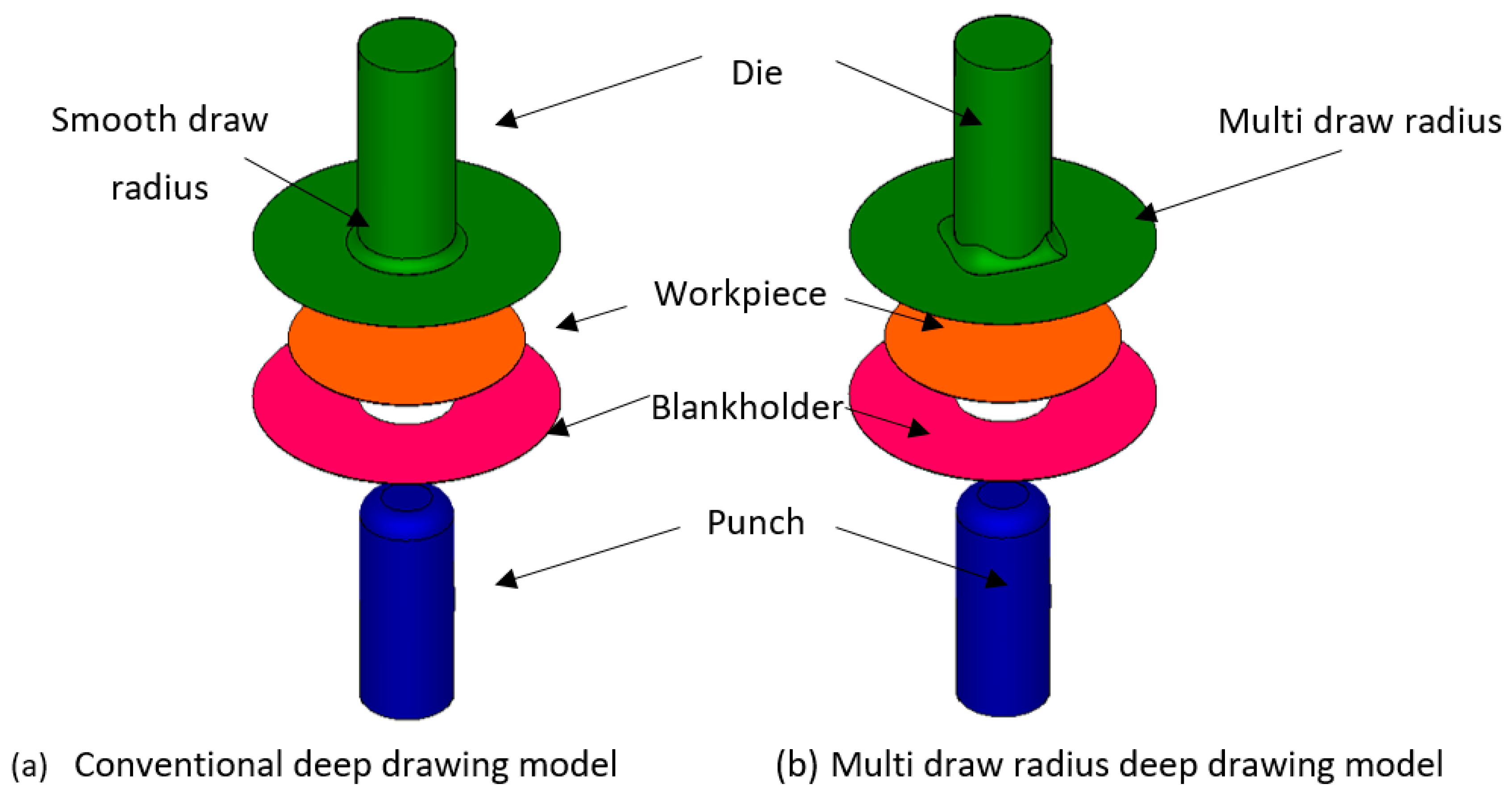
2. Proposed Multi Draw Radius (MDR) Die and Its Principle

As per the deep drawing theory [1], the LDR is the maximum ratio of initial blank diameter to punch diameter in which the cylindrical cup could be formed without any fractures. The LDR also depends upon the type of material used as well as relates to the mechanical property of material being of common concern in the deep drawing process. In terms of fracture, the fracture is commonly generated on the basis of two deep drawing characteristics [1]. Specifically, the first is that the wrinkle defects are generated on the flange due to the overly low blankholder pressure applied which causes the obstacle of material flow into the die. This manner resulted in the generation of cup wall stretching and fractures. Next, the second is that the flange is tightly clamped by applying an overly high blankholder pressure. This manner resulted in the material not being able to be drawn into the die as well as subsequent cup wall stretching and generation of fractures. In addition, the material properties, especially plastic strain ratio (R-value), also affect fractures. As is well known, the R-value is the anisotropy property of the material and depends upon the direction along the plane, at 45°, and at 90° to the rolling direction. Namely, the anisotropy property of the material causes the different material flow and formability in each direction along the plane, at 45°, and at 90° to the rolling direction. As this characteristic causes non-axisymmetric material flow on the flange during the deep drawing process, cup wall stretching can easily be generated, as well as that flange wrinkles can be easily formed. Based on these reasons, to prevent the fracture and increase in deep drawing formability, the prevention of cup wall stretching and flange wrinkle should be strictly considered. As per previous studies [11,19,20], the working process parameters on deep drawing process, i.e., blankholder pressure, lubricant, and draw radius, were investigated. However, as aforementioned, the anisotropy property of the material in each direction along the plane, at 45°, and at 90° to the rolling direction related to draw radius die design for reducing the non-axisymmetric material flow during deep drawing process has not yet been investigated. In the present research, the multi draw radius die (or so-called MDR die) is proposed to reduce the non-axisymmetric material flow during deep drawing process and prevent fracture as well as to increase in LDR. The schematic of MDR die was shown in Figure 1. The draw radius was designed related to the anisotropy property of the material in each direction along the plane, at 45°, and at 90° to the rolling direction to reduce the non-axisymmetric material flow during the deep drawing process. As per deep drawing theory, the LDR should be treated as the baseline. It gives only estimated values and does not take into account many factors. Therefore, in the present research, to compare the formability based on the LDR between conventional die and MDR die applications, the other process parameters affecting LDR, excluding die types, were set with the same conditions for both cases of conventional and MDR die applications.
Figure 2 shows the principle of MDR die based on the material flow characteristic. The comparison of schematic of material flow characteristic between conventional and MDR dies was illustrated. In the case of conventional die as shown in Figure 2a, owing to the effects of the anisotropy property of the material in each direction along the plane, at 45°, and at 90° to the rolling direction, the non-axisymmetric material flow characteristic was formed. By contrast, to encounter these effects, the MDR die was proposed. The different draw radius positioned in each direction along the plane, at 45°, and at 90° to the rolling direction was designed. Based on this MDR die, the non-axisymmetric material flow characteristic due to the effects of the anisotropy property of the material could be reduced by using a different draw radius in each direction along the plane, at 45°, and at 90° to the rolling direction, as shown in Figure 2b. Therefore, the cup wall stretching and fracture prevention could be achieved, and the LDR could also be increased.

3. The FEM Simulation and Experimental Procedures

In the present research, the FEM simulation was used as a tool to clarify the deep drawing mechanism of MDR die based on the material flow. The nonlinear FEM commercial code HyperForm 14.0 with RADIOSS script (Altair Engineering Inc., Troy, MI, USA) as the solver was used for FEM simulation of the deep drawing process. The investigated model of MDR die application is shown in Figure 3a. In addition, to clearly understand the deep drawing mechanism of MDR die application, the deep drawing mechanism of conventional die application was also investigated as the model shown in Figure 3b. These 3-D deep drawing models were created by Cimatron 3 (3D Systems Inc., Givat Shmuel, Israel) and then imported as IGES file into HyperForm. The HyperMesh preprocessor was used to create the mesh. The initial blank was set as elastic–plastic and meshed into finite elements of “shell” type. The 4 node quadrilateral shape elements of approximately of 3500 elements were generated. The adaptive remeshing was also set. After remeshing, to lead rather smooth meshes, the combination of 4 node quadrilateral shape elements and triangular shape elements were generated. The tool including punch, die, and blankholder were meshed with the rigid mesh type to prevent their deformations during the deep drawing process. The blankholder pressure was set as gap type. The gap of material thickness was applied. In the present research, the forming limit diagram (FLD) was used to clarify the forming characteristics as well as to predict the fracture zone on deep drawn parts. The workpiece used in this present research was medium carbon steel grade SPCC (JIS standard) with the thickness of 0.5 mm. The material properties of flow curve equation and plastic strain ratio (R-value) were prepared as input parameters for FEM simulation. The workpiece material was described with an elastoplastic, power exponent, isotropic plasticity model of Hollomon power law hardening model, with the constitutive equation determined from the stress–strain curve using the tensile test data. The other necessary material properties, such as the Young’s modulus, Poisson’s ratio, and ultimate tensile strength are given in Table 1. As per the literature [30,31,32], for the static compression test, the friction coefficient was set to be from 0.1 to 0.3. In the present research, based on the deep drawing process with lubricant used, the contact surface model was defined by a Coulomb friction law, and friction coefficient (µ) of 0.10 was applied. It was applied for both cases of conventional and MDR deep drawing processes to ignore the effect of lubricant use. Next, the diameters of punch and die were 40.0 and 41.0 mm, respectively, in which the clearance of 0.5 mm was set. The tool radius for conventional die was set following deep drawing theory [1]. Namely, a punch radius of 8.0 mm and die radius of 3.5 mm were set. The MDR draw radii of 3.5–5, 3.5–7, and 3.5–9 mm were investigated. On the basis of deep drawing theory [1], the LDR for this material was approximately of 2.25. Three levels of initial blank diameter of 90, 110, and 115 mm in which the drawing ratios of 2.25, 2.75, and 2.88 were investigated.
The laboratory experiments were performed to validate the FEM simulation results. Figure 4 shows the press machine, which includes a universal sheet metal testing machine (Model SAS-350D, JT Toshi Inc., Minato-ku, Japan) and the sets of conventional die and MDR die applications. The initial blanks were prepared using a wire electrical discharge machine (Wire-EDM) (Model AQ325L, Sodick Co., Ltd., Ishikawa, Japan). The obtained deep drawn parts were sectioned by wire electrical discharge machine for cup wall thickness examination. The cup wall thickness was measured. Five samples from each deep drawing condition were used to inspect the obtained deep drawing parts. The cup wall thickness was calculated based on these obtained deep drawing parts and the average cup wall thickness values were reported and compared with those analyzed by the FEM simulation.

4. Results and Discussion

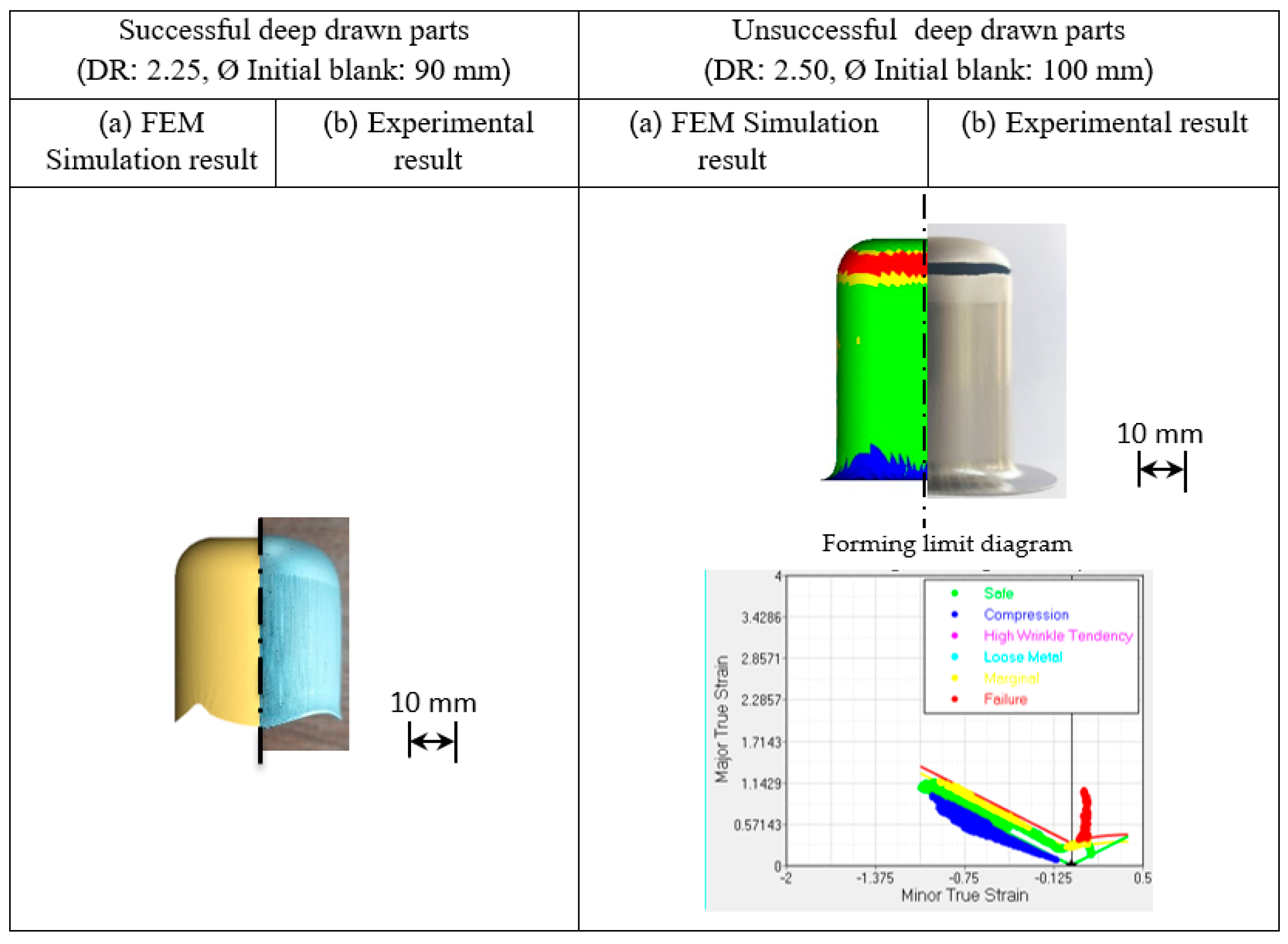
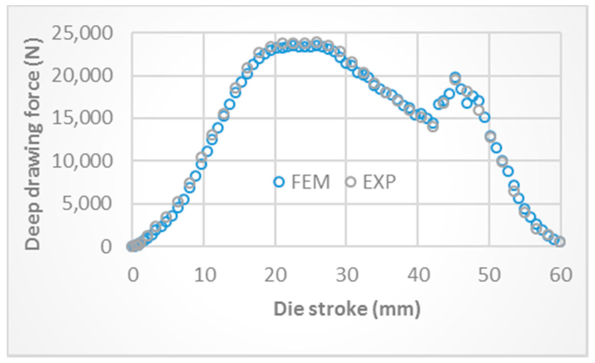
4.1. The Validation of FEM Simulation Use

The FEM simulation was used, in the present research, as a tool for characterization of the deep drawing mechanism and prediction of the obtained deep drawn parts. Therefore, although the commercial finite element code HyperForm was used, the accuracy of the FEM simulation results should be again validated before starting the discussion section of FEM simulation results. As the validation of the FEM simulation results shows in Figure 5, by comparing with the laboratory experiments, the FEM simulation results showed the successful deep drawn parts and unsuccessful deep drawn parts which corresponded well with the experiments. In addition, the FEM simulation results also showed the earing defects and fracture which corresponded well with the experimental results. The unsuccessful deep drawn part in which the fracture generated as shown in Figure 5b, the FEM simulation result corresponded well with the experiments. On the basis of FLD, the fracture was generated on corner zone and a circumferential character was formed which agreed well with the fracture generated on deep drawn part obtained by experiment. The cup wall thickness was also examined. The comparisons of cup wall thickness distribution between FEM simulation and experimental results are illustrated in Figure 6. The FEM simulation results showed that the predicted cup wall thickness distributions corresponded well with the experiments, in which the errors in the analyzed cup wall thickness were approximately 3% compared with the experimental results. Finally, the deep drawing force was also recorded during experiments to validate the deep drawing force analyzed by FEM simulation. Figure 7 shows the comparison of deep drawing force obtained by FEM simulation and experiment. Again, the analyzed deep drawing force by FEM simulation corresponded well with the experiment, in which the error in the analyzed deep drawing force was approximately 1% compared with the experimental result.

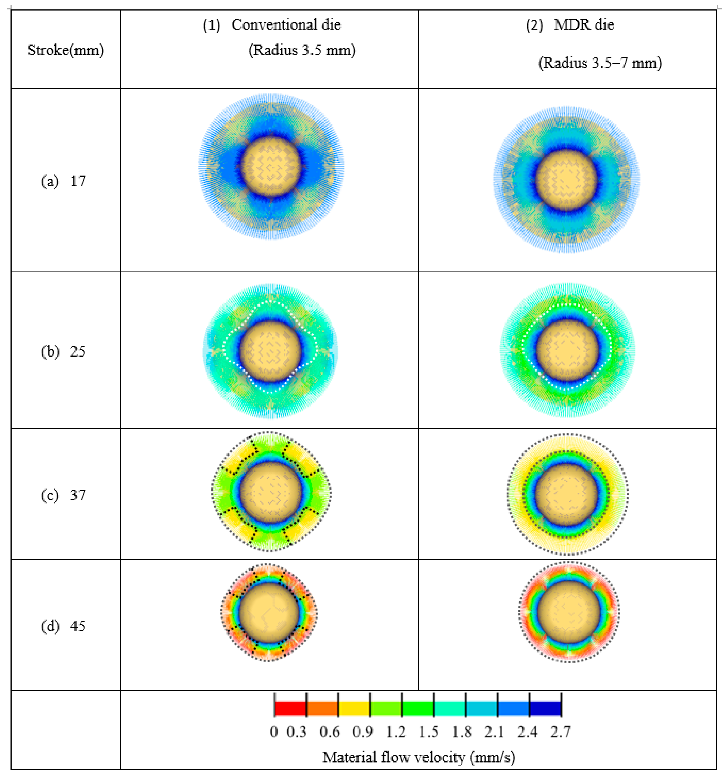
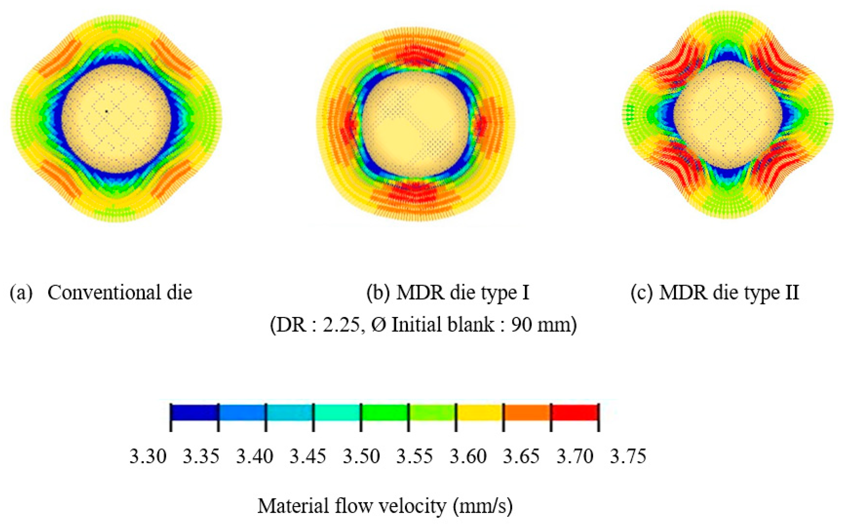
4.2. Comparison of Material Flow Analysis between Conventional Die and MDR Die Applications

The principle of MDR die application, as aforementioned, was clearly characterized based on the material flow obtained by FEM simulation. As shown in Figure 8, the comparison of material flow between conventional and MDR die applications was illustrated. For the deep drawing stroke of approximately 17 mm, the material flow showed that the same manner in both cases of conventional and MDR die applications could be observed as shown in Figure 8a. These results corresponded well with deep drawing theory [1]. For the deep drawing stroke of approximately 25 mm, in the case of conventional die application as shown in Figure 8b-1, the effects of the anisotropy property of the material on material flow were clearly illustrated. The non-axisymmetric material flow on flange was clearly illustrated as depicted by dashed lines. These results corresponded well with deep drawing theory [1]. By contrast, in the case of MDR die application as shown in Figure 8b-2, the effects of the anisotropy property on material flow were compensated by multi draw radius especially on the large draw radius zone. However, owing to that there were large radius zones formed on MDR die, it was observed that the material flow velocity in the case of MDR die application was larger than that in the case of conventional die application especially on the large radius zone of MDR die. Moreover, the reduction of the non-axisymmetric material flow characteristic on flange could be obtained and clearly illustrated as depicted by dashed lines. Next, the deep drawing stroke was increased to approximately 37 mm, as shown in Figure 8c, and the effects of the anisotropy property of the material on material flow were clearly evidenced in the case of conventional die application as shown in Figure 8c-1. It was clearly observed that the non-axisymmetric material flow on flange was clearly illustrated as depicted by dashed lines. The flange shape was not a circular but had become square. By contrast, in the case of MDR die application as shown in Figure 8c-2, the effects of the anisotropy property of the material on material flow were continuously compensated by multi draw radius. The reduction of the non-axisymmetric material flow characteristic on flange and the asymmetry of the flange were clearly illustrated. The flange was in a more circular shape. Finally, in the case of conventional die application, the effects of the anisotropy property of the material on material flow were stronger as the deep drawing stroke increased as shown in Figure 8d-1. Vice versa, in the case of MDR die application, the effects of the anisotropy property of the material on material flow were continuously compensated by multi draw radius. The reduction of the non-axisymmetric material flow characteristic on flange were clearly illustrated as well as that the asymmetry of the flange could be continuously reduced and the flange was more circular in shape as shown in Figure 8d-2. These results revealed that by using MDR die application, the effects of the anisotropy property of the material on material flow could be compensated during the deep drawing process. The non-axisymmetric material flow characteristic on the flange and the asymmetry of the flange could be reduced during the deep drawing process. This resulted in preventing cup wall stretching and fracture as well as that the LDR could be increased.

4.3. MDR Die Design Related to the Anisotropy Property of the Material

As mentioned in the previous section, the results illustrated that the effects of the anisotropy property of the material on material flow were related to the draw radius. Therefore, the MDR die should be strictly designed by relating to the anisotropy property of the material in each direction along the plane, at 45°, and at 90° to the rolling direction. Figure 9b,c show the deep drawn parts obtained by MDR die application related to the anisotropy property of the material. Figure 9b shows the MDR die application by designing the larger draw radius positioned for at 45° to the rolling direction and the small draw radius positioned for along the plane and at 90° to the rolling (named MDR type I). By contrast, Figure 9c shows the MDR die application by designing the larger draw radius positioned for along the plane and at 90° to the rolling direction and the small draw radius positioned for at 45° to the rolling (named MDR type II). The results showed that, in the case of LDR 2.25 (initial blank diameter of 90 mm), the deep drawn parts could be formed by conventional die application as shown in Figure 9a-1. This result corresponded well with the deep drawing theory and literature that by using conventional die application, the deep drawn part could be formed with LDR [1]. The results also showed that the deep drawn parts could be formed by using MDR die application in both cases of MDR die designs as shown in Figure 9b-1,c-1. However, it was observed that in terms of earing defect, the MDR type II showed a larger earing defect than that of MDR type I as well as than that of conventional die application. In addition, it was also observed that the earing defect obtained by using MDR type I was smaller than that of conventional die application. As these results show, to deep draw with LDR, the deep drawn parts could be achieved by using MDR die application. In addition, the quality of deep drawn parts obtained by MDR type I in terms of earing defects was better than that obtained by conventional die. The results illustrate that the MDR die design should be strictly considered as related to the anisotropy property of the material in each direction along the plane, at 45°, and at 90° to the rolling direction. Next, to deep draw over LDR, the result showed that by using conventional die application, the deep drawn part could not be achieved, and a fracture was generated as shown in Figure 9a-2. Based on the FLD, the FEM simulation result clearly showed that the fracture characteristic is formed as a circumferential character. This result agreed well with deep drawing theory [1]. By contrast, in using the MDR die application, the results illustrated that the deep drawn part could be achieved by MDR die type I application as shown in Figure 9b-2. However, using MDR die type II, the deep drawn part could not be achieved. The six ears were also characterized on the basis of FLD, and a fracture was also generated on the top of the deep drawn part as shown in Figure 9c-2. Owing to the anisotropy property of the material in each direction along the plane, at 45°, and at 90° to the rolling direction related to the formability [1], therefore, the design of the larger draw radius positioned at 45° to the rolling direction and the smaller draw radius positioned along the plane and at 90° to the rolling direction was suggested. As shown in Figure 10, the MDR die type II resulted in that the larger non-axisymmetric material flow on flange was formed compared with those in the cases of conventional and MDR die type I applications. As these material flow analyses show, as aforementioned, the non-axisymmetric material flow characteristic on flange and the asymmetry of the flange could be increased and cup wall stretching and fracture were then easier to generate.

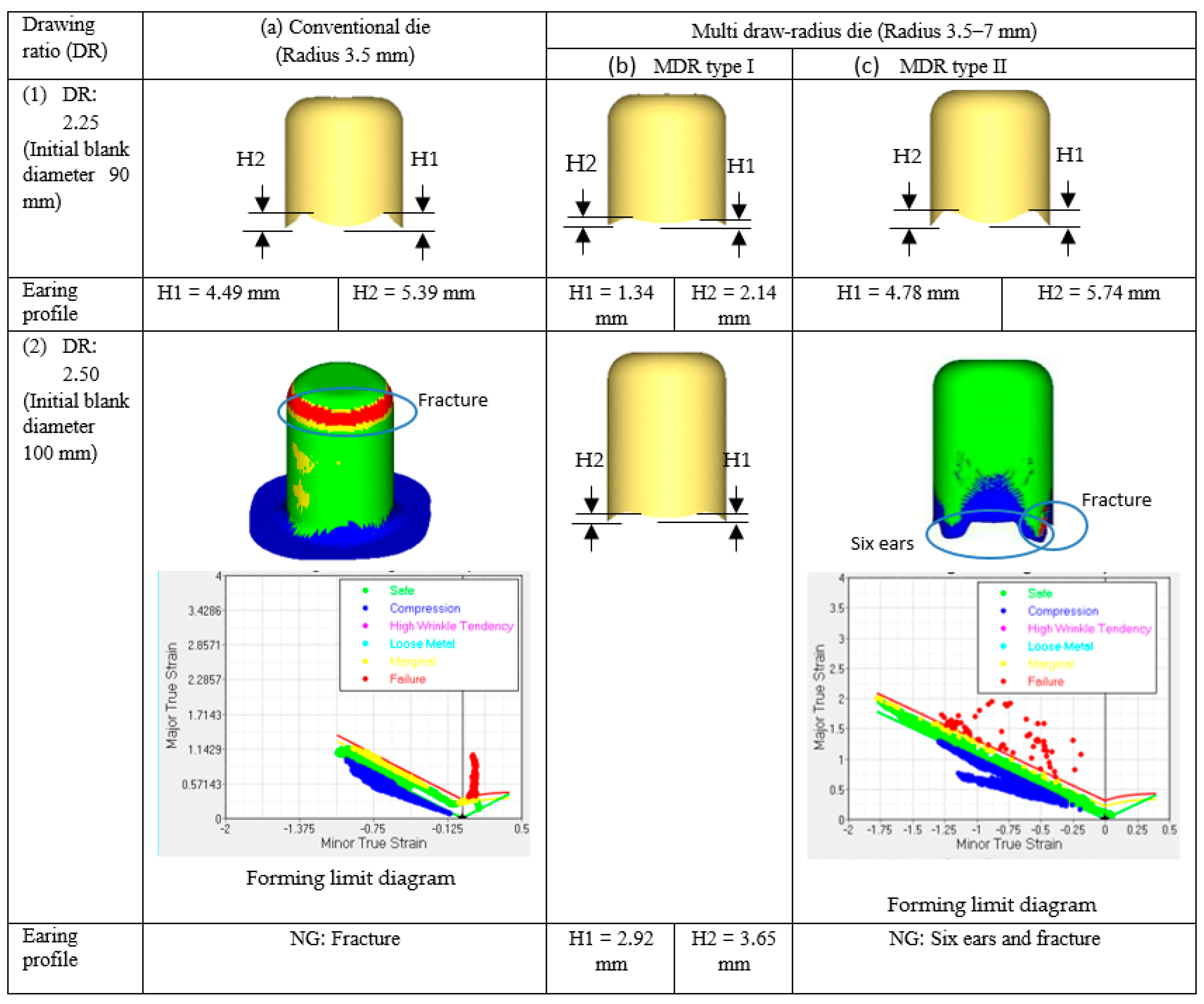
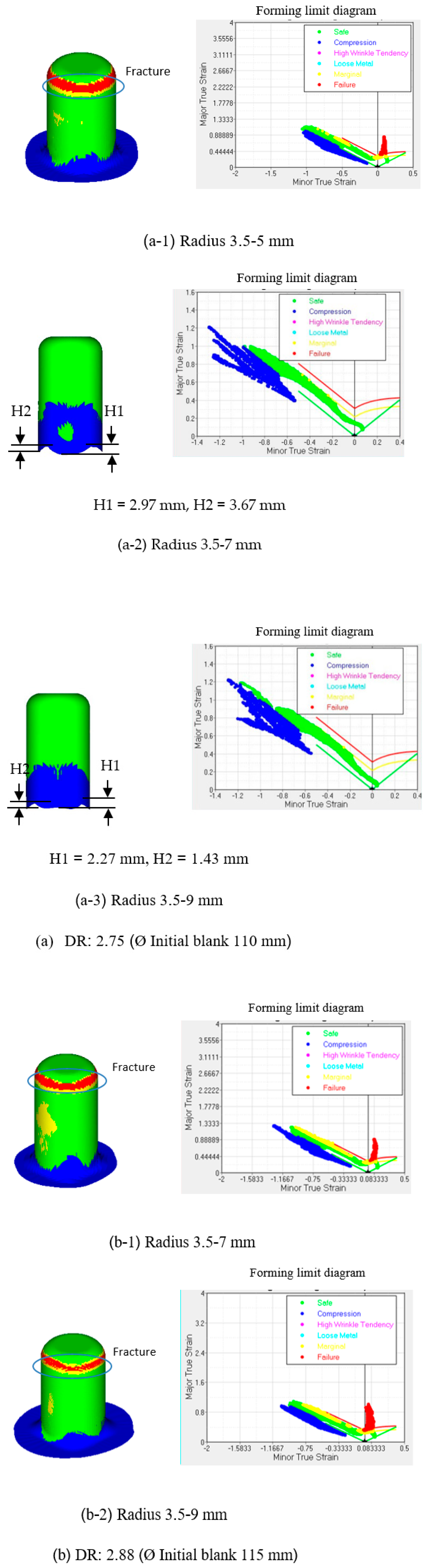
4.4. Examination of Drawing Ratio with Respect to Multi Draw Radius Dies

Figure 11 shows the obtained deep drawn parts with respect to various MDR dies and drawing ratios. The drawing ratios of 2.75 and 2.88 which were larger than LDR were investigated, as respectively shown in Figure 11a,b. On the basis of deep drawing theory [1], the draw radius of 3.5 mm was recommended and then it was set as a small draw radius in MDR die. Next, the large draw radius values of 5, 7, and 9 mm were set as the large draw radius. With the drawing ratio of 2.75 as shown in Figure 11a, the results showed that the deep drawn parts could not be achieved when the large radius of 5 mm was set, as shown in Figure 11a-1. This result could be explained by the draw radius of 5 mm, set as the large radius, was too small to reduce the non-axisymmetric material flow characteristic during the deep drawing process. Conversely, as the large radius was increased, the greater reduction of non-axisymmetric material flow characteristic could be achieved, and then the deep drawn parts could be achieved as for the large radius values set as 7 and 9 mm, as shown in Figure 11a-2,a-3, respectively. The increases in large radius resulted in that, as aforementioned, the non-axisymmetric material flow characteristic on the flange was reduced, and the asymmetry of flange could also be reduced. This resulted in the more circular flange shape. However, it was also observed that owing to the large radius of 9 mm, the non-axisymmetric material flow characteristic on the flange could be reduced, getting a more circular flange shape than that for the large radius of 7 mm during the deep drawing process. The earing defect in the case of large radius 9 mm was smaller than that obtained in the case of the large radius of 7 mm. Next, with the drawing ratio of 2.88 as shown in Figure 11b, the results showed that the deep drawn parts could not be achieved. Namely, owing to the overly large drawing ratio (overly large initial blank diameter) applied, the non-axisymmetric material flow on the flange could not be effectively reduced during a whole deep drawing process. These results revealed that in the present research, the LDR could be increased by approximately 22.22% using MDR die application. In addition to the increases in LDR, the quality of deep drawn parts in terms of cup wall thickness and earing defects were also increased. Specifically, the earing defect could be reduced approximately 40% compared with the use of conventional die as shown in Figure 9 and Figure 11. Next, the more uniform cup wall thickness in each direction along the plane, at 45°, and at 90° to the rolling direction could be obtained by comparing with the use of conventional die as shown in Figure 12. However, the MDR die should be strictly design related to the anisotropy property of the material in each direction along the plane, at 45°, and at 90° to the rolling direction which was suggested in the previous section.

4.5. Confirmation of MDR Die Application

To validate the accuracy of the MDR die application obtained by FEM simulation, the FEM simulation results were compared with those obtained by experimental results, as shown in Figure 13. The FEM simulation results showed that the predicted deep drawn parts corresponded well with the experiments as shown in Figure 13a-1,b-1 in the cases of MDR draw radius of 3.5–7 and 3.5–9 mm, respectively. In terms of cup wall thickness, the FEM simulation results showed that the predicted cup wall thickness corresponded well with the experiments as shown in Figure 13a-2,b-2 in the cases of MDR draw radius of 3.5–7 and 3.5–9 mm, in which the errors in the analyzed cup wall thickness were approximately 3% compared with the experimental results.

5. Conclusions

To increase the drawing ratio and overcome the LDR, the MDR die application was proposed in the present research. First, the conceptual design of MDR die was proposed, and its principle was also clearly elucidated in the present research by FEM simulation based on the material flow. The absolute validation of FEM simulation use was also performed. By using MDR die application, it was revealed that the non-axisymmetric material flow characteristic on the flange as well as the asymmetry of flange shape could be reduced. Specifically, during deep drawing process, the MDR could compensate the effects of the anisotropy property of the material on material flow characteristics in each direction along the plane, at 45°, and at 90° to the rolling direction as well as that the non-axisymmetric material flow characteristic on flange could be effectively reduced and, by reducing the asymmetry of flange, a more circular flange shape could be obtained. Therefore, wall cup stretching could be reduced as well as the delay of fracture. Based on this principle, the LDR could be increased. However, in the present research, the proper MDR die design related to the anisotropy property of the material in each direction along the plane, at 45°, and at 90° to the rolling direction was suggested. Specifically, the larger draw radius positioned for at 45° to the rolling direction and the smaller draw radius positioned for along the plane and at 90° to the rolling direction were recommended. Again, the experiments were also carried out to validate the FEM simulation results in the case of MDR die application. The FEM simulation results showed that the predicted deep drawn parts corresponded well with the experimental results. In addition, the FEM simulation results showed that the predicted cup wall thickness corresponded well with the experiments, in which the errors in the analyzed cup wall thickness were approximately 3% compared with the experimental results. The results of the present research reveal that the LDR could be increased approximately 22.22% using MDR die application. In addition to the increases in LDR, in terms of quality of deep drawn part, the deep drawn parts obtained by MDR die application showed a smaller earing defect compared with those obtained by conventional die. The decreases in earing defect of approximately 40% could be achieved as well as the more uniform cup wall thickness in each direction along the plane, at 45°, and at 90° to the rolling direction could be obtained. However, the MDR die should be strictly design related to the anisotropy property of the material in each direction along the plane, at 45°, and at 90° to the rolling direction as suggested in the present research.

Author Contributions

Conceptualization, W.P. and S.T.; data curation, W.P.; funding acquisition, W.P.; investigation, W.P.; methodology, W.P. and S.T.; project administration, W.P.; supervision, S.T.; writing—original draft, W.P.; writing—review & editing, S.T. All authors have read and agreed to the published version of the manuscript.

Funding

This research was supported by a grant from The Thailand Research Fund (TRF) and Rajamangala University of Technology Rattanakosin under Grant No. MRG6280205.

Acknowledgments

The authors would especially like to thank Rudeemas Jankree and Jaksawat Sriborwornmongkol, for their help in this research. The authors would like to express our gratitude to Pravitr Paramaputi, Srisahawattanakij Co. Ltd., for his support in the Cimatron v.3 program.

Conflicts of Interest

The authors declare no conflict of interest.

References

  1. Lange, K. Handbook of Metal Forming; McGraw-Hill Inc.: New York, NY, USA, 1985. [Google Scholar]
  2. Ahmadi, M.; Sadeghi, B.M.; Arabi, H. Experimental and numerical investigation of V-bent anisotropic 304L SS sheet with spring-forward considering deformation-induced martensitic transformation. Mater. Des. 2017, 123, 211–222. [Google Scholar] [CrossRef]
  3. Thipprakmas, S. Finite element analysis of sided coined-bead technique in precision V-bending process. Int. J. Adv. Manuf. Technol. 2012, 65, 679–688. [Google Scholar] [CrossRef]
  4. Lin, B.-T.; Yang, C.-Y. Using a punch with micro-ridges to shorten the multistage deep drawing process for stainless steels. Int. J. Adv. Manuf. Technol. 2016, 88, 2693–2703. [Google Scholar] [CrossRef]
  5. Thipprakmas, S.; Komolruji, P. Analysis of bending mechanism and spring-back characteristics in the offset Z-bending process. Int. J. Adv. Manuf. Technol. 2015, 85, 2589–2596. [Google Scholar] [CrossRef]
  6. Liu, Y.; Tang, B.; Hua, L.; Mao, H. Investigation of a novel modified die design for fine-blanking process to reduce the die-roll size. J. Mater. Process. Technol. 2018, 260, 30–37. [Google Scholar] [CrossRef]
  7. Thipprakmas, S.; Phanitwong, W. Finite element analysis of flange-forming direction in the hole flanging process. Int. J. Adv. Manuf. Technol. 2011, 61, 609–620. [Google Scholar] [CrossRef]
  8. Zhang, Z.; Cheng, L.; Sun, H.; Bao, H. Finite element simulation of the punch with inclined edge in the sheet metal blanking process. Int. J. Comput. Sci. Math. 2018, 9, 377–389. [Google Scholar] [CrossRef]
  9. Thipprakmas, S.; Komolruji, P.K.; Phanitwong, W. Comparison of Offset and Wiping Z-Die Designs for Precision Z-Bent Part Fabrication. J. Manuf. Sci. Eng. 2018, 140, 021015. [Google Scholar] [CrossRef]
  10. Zhang, C.-B.; Gong, F. Deep drawing of cylindrical cups using polymer powder medium based flexible forming. Int. J. Precis. Eng. Manuf. Technol. 2018, 5, 63–70. [Google Scholar] [CrossRef]
  11. Modi, B.; Kumar, D.R. Optimization of process parameters to enhance formability of AA 5182 alloy in deep drawing of square cups by hydroforming. J. Mech. Sci. Technol. 2019, 33, 5337–5346. [Google Scholar] [CrossRef]
  12. Cha, W.-G.; Müller, S.; Albers, A.; Volk, W. Formability consideration during bead optimisation to stiffen deep drawn parts. Prod. Eng. 2018, 12, 691–702. [Google Scholar] [CrossRef]
  13. Abe, Y.; Mori, K.-I.; Maeno, T.; Ishihara, S.; Kato, Y. Improvement of sheet metal formability by local work-hardening with punch indentation. Prod. Eng. 2019, 13, 589–597. [Google Scholar] [CrossRef]
  14. Lee, M.S.; Kim, S.J.; Seo, H.Y.; Kang, C.-G. Investigation of Formability and Fiber Orientation in the Square Deep Drawing Process with Steel/CFRP Hybrid Composites. Int. J. Precis. Eng. Manuf. 2019, 20, 2019–2031. [Google Scholar] [CrossRef]
  15. Liu, J.; Zhuang, L. Cylindrical cup-drawing characteristics of aluminum-polymer sandwich sheet. Int. J. Adv. Manuf. Technol. 2018, 97, 1885–1896. [Google Scholar] [CrossRef]
  16. Wang, C.; Cheng, L.D.; Liu, Y.; Zhang, H.; Wang, Y.; Shan, D.B.; Guo, B. Research on micro-deep drawing process of concial part with ultra-thin copper foil using multi-layered DLC film-coated die. Int. J. Adv. Manuf. Technol. 2018, 100, 569–575. [Google Scholar] [CrossRef]
  17. Li, W.; Fu, M.; Wang, J.L.; Meng, B. Grain size effect on multi-stage micro deep drawing of micro cup with domed bottom. Int. J. Precis. Eng. Manuf. 2016, 17, 765–773. [Google Scholar] [CrossRef]
  18. Gong, F.; Yang, Z.; Chen, Q.; Xie, Z.; Shu, D.; Yang, J. Influences of lubrication conditions and blank holder force on micro deep drawing of C1100 micro conical–cylindrical cup. Precis. Eng. 2015, 42, 224–230. [Google Scholar] [CrossRef]
  19. Ma, J.; Gong, F.; Yang, Z.; Zeng, W. Micro deep drawing of C1100 micro square cups using microforming technology. Int. J. Adv. Manuf. Technol. 2016, 82, 1363–1369. [Google Scholar] [CrossRef]
  20. Sen, N.; Karaağaç, I.; Kurgan, N. Experimental research on warm deep drawing of HC420LA grade sheet material. Int. J. Adv. Manuf. Technol. 2016, 87, 3359–3371. [Google Scholar] [CrossRef]
  21. Wang, W.; Chen, S.; Tao, K.; Gao, K.; Wei, X. Experimental investigation of limit drawing ratio for AZ31B magnesium alloy sheet in warm stamping. Int. J. Adv. Manuf. Technol. 2017, 92, 723–731. [Google Scholar] [CrossRef]
  22. Singh, A.; Basak, S.; Lin Prakash, P.S.; Roy, G.G.; Jha, M.N.; Mascarenhas, M.; Panda, S.K. Prediction of earing defect and deep drawing behavior of commercially pure titanium sheets using CPB06 anisotropy yield theory. J. Manuf. Process. 2018, 33, 256–267. [Google Scholar] [CrossRef]
  23. Saxena, R.K.; Dixit, P.M. Finite element simulation of earing defect in deep drawing. Int. J. Adv. Manuf. Technol. 2009, 45, 219–233. [Google Scholar] [CrossRef]
  24. Dhaiban, A.A.; Soliman, M.-E.S.; El-Sebaie, M. Finite element modeling and experimental results of brass elliptic cups using a new deep drawing process through conical dies. J. Mater. Process. Technol. 2014, 214, 828–838. [Google Scholar] [CrossRef]
  25. Dehghani, F.; Salimi, M. Analytical and experimental analysis of the formability of copper-stainless-steel 304L clad metal sheets in deep drawing. Int. J. Adv. Manuf. Technol. 2015, 82, 163–177. [Google Scholar] [CrossRef]
  26. Kesharwani, R.K.; Basak, S.; Panda, S.; Pal, S. Improvement in limiting drawing ratio of aluminum tailored friction stir welded blanks using modified conical tractrix die. J. Manuf. Process. 2017, 28, 137–155. [Google Scholar] [CrossRef]
  27. Bandyopadhyay, K.; Panda, S.; Saha, P.; Padmanabham, G. Limiting drawing ratio and deep drawing behavior of dual phase steel tailor welded blanks: FE simulation and experimental validation. J. Mater. Process. Technol. 2015, 217, 48–64. [Google Scholar] [CrossRef]
  28. Faraji, G.; Mashhadi, M.M.; Hashemi, R. Using the finite element method for achieving an extra high limiting drawing ratio (LDR) of 9 for cylindrical components. CIRP J. Manuf. Sci. Technol. 2010, 3, 262–267. [Google Scholar] [CrossRef]
  29. Halkaci, H.S.; Turkoz, M.; Dilmec, M. Enhancing formability in hydromechanical deep drawing process adding a shallow draw bead to the blank holder. J. Mater. Proc. Technol. 2014, 214, 1638–1646. [Google Scholar] [CrossRef]
  30. Karagiozova, D.; Shu, D.; Lu, G.; Xiang, X. On the energy absorption of tube reinforced foam materials under quasi-static and dynamic compression. Int. J. Mech. Sci. 2016, 105, 102–116. [Google Scholar] [CrossRef]
  31. Ha, N.S.; Lu, G.; Xiang, X. High energy absorption efficiency of thin-walled conical corrugation tubes mimicking coconut tree configuration. Int. J. Mech. Sci. 2018, 148, 409–421. [Google Scholar] [CrossRef]
  32. Ha, N.S.; Lu, G.; Xiang, X. Energy absorption of a bio-inspired honeycomb sandwich panel. J. Mater. Sci. 2019, 54, 6286–6300. [Google Scholar] [CrossRef]
Figure 1. Schematic of deep drawing model and types of deep drawing die: (a) Deep drawing model; (b) Conventional die; (c) Multi draw-radius die.
Metals 10 00870 g001
Figure 2. Principle of multi draw radius die based on the material flow characteristic: (a) Conventional die; (b) Multi draw-radius die.
Metals 10 00870 g002
Figure 3. Deep drawing simulation models: (a) Conventional deep drawing model; (b) Multi draw-radius deep drawing model.
Metals 10 00870 g003
Figure 4. Press machine and set of punch and die: (a) Press machine (Universal sheet metal testing machine); (b) Punch; (c) Blankholder; (d) Conventional die (radius 3.5 mm); (e) Multi draw-radius die (radius 3.5–7mm); (f) Multi draw-radius die (radius 3.5–9mm).
Metals 10 00870 g004
Figure 5. Comparison of deep drawn parts obtained by FEM simulation and experimental results: (a) FEM Simulation result; (b) Experimental result.
Metals 10 00870 g005
Figure 6. Cup wall thickness distribution between FEM simulation and experimental results: (a) Position for measurement; (b) 0° to rolling direction; (c) 45° to rolling direction; (d) 90° to rolling direction.
Metals 10 00870 g006
Figure 7. Comparison of deep drawing force between FEM simulation and experimental results (DR: 2.25; Ø initial blank: 90 mm).
Metals 10 00870 g007
Figure 8. Comparison of the deep drawing mechanism between conventional and multi draw radius (MDR) die applications: (a) Die stroke 17 mm; (b) Die stroke 25 mm; (c) Die stroke 37 mm; (d) Die stroke 45 mm.
Metals 10 00870 g008
Figure 9. MDR die design related to the anisotropy property of the material: (a) Conventional die (Radius 3.5 mm); (b) MDR type I; (c) MDR type II.
Metals 10 00870 g009
Figure 10. Material flow with respect to deep drawing dies: (a) Conventional die; (b) MDR die type I; (c) MDR die type II.
Metals 10 00870 g010
Figure 11. Multi draw radius die application with respect to various DRs: (a) DR: 2.75 (Ø Initial blank 110 mm); (b) DR: 2.88 (Ø Initial blank 115 mm).
Metals 10 00870 g011
Figure 12. Comparison of cup wall thickness between conventional and MDR die applications obtained by FEM simulation (DR: 2.25; initial blank diameter: 90 mm). (a) Conventional die (Radius 3.5 mm); (b) Multi draw radius die type I (Radius 3.5–7 mm).
Metals 10 00870 g012
Figure 13. Comparison of theoretical and experimental results of multi draw radius die. (DR: 2.75; Ø initial blank: 110 mm): (a) Draw radius 3.5-7 mm; (b) Draw radius 3.5-9 mm.
Metals 10 00870 g013aMetals 10 00870 g013b
Table 1. FEM simulation and experimental conditions.
Object typeSheet material: elastic–plastic
Tool (punch, die, blankholder): rigid
Sheet materialMedium carbon steel (SPCC, JIS), thickness: 0.5 mm
Ultimate tensile strength: 317 MPa
Young’s modulus: 208 GPa
%Elongation: 51
Poisson’s ratio: 0.33
Constitutive equation σ ¯ = 554.43 ε ¯ 0.23 + 208
Blankholder forceGap type
Plastic strain ratio
(R value)
0° to rolling direction2.1
45° to rolling direction1.9
90° to rolling direction2.6
Blank diameter90, 100, 110, and 115 mm
Tool geometryPunch radius8 mm
Punch diameter40 mm
Conventional die radius3.5 mm
MDR die radius3.5–5, 3.5–7, 3.5–9 mm
Punch velocity5 mm/s
Clearance0.5 mm
Friction coefficient (µ)0.10

