Article

Effect of Tool Geometry and Welding Parameters on Friction Stir Welded Lap Joint Formation with AA2099-T83 and AA2060-T8E30 Aluminium Alloys

1
LORTEK Technological Centre, Basque Research and Technology Alliance (BRTA), Arranomendia kalea 4A, 20240 Ordizia, Spain
2
Mondragon Unibertsitatea, Faculty of Engineering (MU-ENG), Loramendi Kalea 4, 20500 Arrasate-Mondragon, Spain
*
Author to whom correspondence should be addressed.
Metals 2020, 10(7), 872; https://doi.org/10.3390/met10070872
Submission received: 27 May 2020 / Revised: 18 June 2020 / Accepted: 23 June 2020 / Published: 1 July 2020
(This article belongs to the Special Issue Friction Stir Welding of Lightweight Alloys)

Abstract

:
In this paper the effect of tool geometry and welding parameters on friction stir welded lap joints with AA2099-T83 and AA2060-T8E30 aluminium alloys has been investigated through the study of the material flow and weld formation along with the reaction forces during friction stir welding (FSW) for various sets of welding parameters and two FSW tools with different geometrical features. The results showed that welding parameters and tool probe geometry strongly affect the characteristics of the typical defect features (hook and cold lap defects) of the friction stir welded lap joints. From the relationship established between the welding parameters, tool probe geometry and the hook and cold lap defect formation, some guidelines are concluded with the objective of guaranteeing appropriate FSW lap joint properties.

Graphical Abstract

1. Introduction

Currently, riveting is the most used joining technology for manufacturing reinforced panels of aircraft structures [1]. However, there are important disadvantages in the use of this technology that have to be solved. Among them, the low productivity and the significant contribution to weight increase are the most significant ones. By contrast with riveting, welded structures show remarkable benefits such as reductions in the number of parts to produce the structures, weight saving as well as significant reductions in manufacturing time and cost. Nowadays the most promising alternative joining technologies to riveting for the manufacturing of aircraft structures are laser beam welding (LBW) [2,3,4] and friction stir welding (FSW) [5,6,7]. Indeed, these technologies have already been satisfactorily implemented in different parts of real aircrafts [8]. This paper explores FSW as an alternative to riveting for stringer to skin lap joint manufacturing applied to reinforced panel applications in aeronautics.
As a solid-state welding technology, FSW presents clear benefits over other welding technologies as it makes possible to reduce typical disadvantages that arise in welding of high strength aluminium alloys, such as welding defects (porosity, hot-cracking) and residual stresses. In order to obtain joints of sufficiently high quality, it is important to avoid welding defects as well as to reduce and control the residual stresses as they can reduce the fatigue life of aircraft structures significantly [9]. Although the effect of residual stresses in the fatigue life of aircraft structures is not in the scope of the present work, several authors have shown the possibility to evaluate the residual stresses using different methods [10,11].
There are several works that have already studied FSW applied to lap joints, and more concretely, stringer to skin lap joints for aeronautic applications [12,13,14,15,16,17,18,19,20,21,22,23,24,25]. Dubourg et al. [16] investigated the effects of FSW parameters on the lap joint formation mechanisms using 2024-T3 and 7075-T6 alloys and they concluded that the material flow induced by the tool had critical effects on the FSW joint properties. Ji et al. [21,22] investigated the effects of different tool-probe thread designs on the FSW lap joint properties. They concluded that the thread design of the probe was critical on the plasticized material flow and the resulting lap joint properties. Lap joints were produced using large penetration tools showing that different thread designs can lead to different material flow and joint properties. Thus specific thread designs for large penetration welds were proved to be beneficial compared to conventional threads, producing lap joints with smaller defect features and higher mechanical properties. The most important conclusion that can be extracted from these works is that both FSW tool design and welding parameters play a key role on the minimization of the welding defects that are characteristic of these type of joint configuration: hook and cold lap defects. According to the ISO25239 standard for FSW aluminium alloys [23], the hook is the most relevant imperfection in FSW lap joints and its relevance in mechanical properties of the joints have been shown previously by Rodrigues et al. [24]. Therefore, it is important to define appropriate tool designs and welding parameters to avoid the formation of hooks of important size in order to optimize the mechanical properties of FSW lap joints.
Regarding current innovation trends in new aircraft structure concepts, the research, maturation and launch of the third generation of aluminium-lithium alloys must be mentioned [26,27]. These alloys present a high strength, low density and excellent corrosion resistance. For stringer-skin applications AA2099 (extrusion) and AA2060 (sheet) Al-Li alloys are considered as some of the most interesting candidates for stringer and skin materials respectively. Huang et al. reported results on FSW lap joints using these alloys [27] showing the influence of process parameters to obtain defect-free joints using a screwed tool-probe design. They showed the feasibility to obtain volumetric defect-free joints using very specific process parameters, i.e., 800 rpm and 200 mm/min, but they reported the formation of cavities using lower or higher welding speeds.
The present work was focused on the manufacturing of FSW lap joints using AA2099-T83 and AA2060-T8E30 aluminium alloys. Thus, the main purpose was to investigate the effect of FSW tool geometry and welding parameters on the main FSW lap joint defect formation, understanding material flow and weld formation mechanisms.

2. Materials and Methods

Z shaped extrusions of aluminium alloy AA2099-T83 with a thickness of 2 mm and sheets of aluminium alloy AA2060-T8E30 with a thickness of 2.5 mm were used as base materials in this work. Both alloys were in a T8 hardened temper condition resulting from a combination of solution heat treatment, cold working and artificial aging steps during their production. The materials were provided by Arconic and Israel Aerospace Industries (IAI) (Lod, Israel) and their indicative chemical compositions are shown in Table 1.
FSW joints were performed in overlap configuration where the alloy AA2099-T83 was used as stringer and placed on top of the alloy AA2060-T8E30 which was used as skin. An example of this lap joint is shown in Figure 1a. 120 mm long joints were performed for each investigated welding condition.
Two types of FSW tools were employed to produce lap joints. Both FSW tools had a plane shoulder of 10 mm in diameter and a probe with 4 mm in diameter and 2.5 mm in length. The difference between the tools was the probe design. One probe design consisted in a conventional right handed thread cylindrical probe (Figure 1b) while the other tool had a probe with 3 flats and 3 types of threads in the 3 cylindrical sections (Figure 1c,d). The flats were used to divide the probe in three different threaded sections. All threads were produced with the same pitch and depth dimensions being the only difference among them the thread orientation. One section had a right handed thread, another one a left handed thread and the other one was a neutral thread with no inclination. The main purpose of this probe design was to avoid any preferential vertical plasticized material flow in order to reduce the hook formation, while promoting sufficient flow at the faying surface to break the oxide layers and produce the mixture between the parts to be welded.
The joints were made in an I-STIR PDS 4 machine for FSW (MTS Systems Corp., Eden Prairie, MN, USA) at LORTEK operated in load control. The welding parameters utilised for this study are summarised in Table 2. The axial loads for each tool and welding parameter set were adjusted in initial FSW tests performed under position control so that sufficient contact by the shoulder was guaranteed. All the welds were performed with a tilt angle of 1.5°.
The in-plane reaction forces during the FSW process were recorded by the controller using the pressure transducers and load cells implemented in the FSW machine. Thus, reaction forces in the welding direction (X) and perpendicular to the welding direction (Y) were recorded as well as the spindle torque. A frequency of 40 Hz was employed to log the process forces and torque. An average value of the forces and torque was calculated from all the recorded values in the steady-state region of each weld. These values are used in the later Section 4 where the process forces and torque are discussed.
After welding, specimens for metallographic analysis were cut from the welds, perpendicular to the welding direction. All specimens were obtained from the middle of the 120 mm long joints. Standard grinding and polishing procedures were followed, and diluted Keller’s reagent was used for revealing the microstructure. Weld cross-sections were then examined by optical microscopy using an Olympus GX51 light optical microscope (Olympus Corp., Tokyo, Japan).

3. Results and Discussion

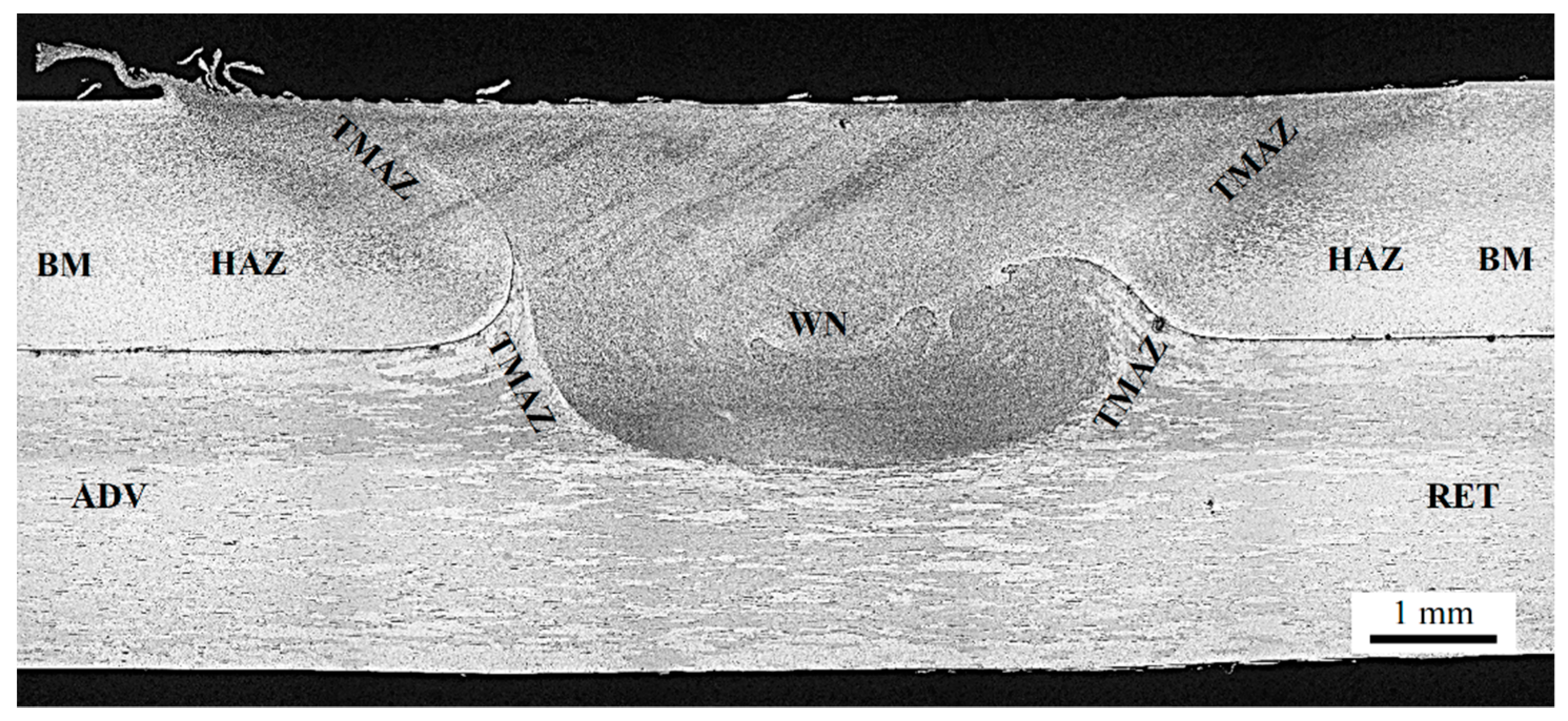
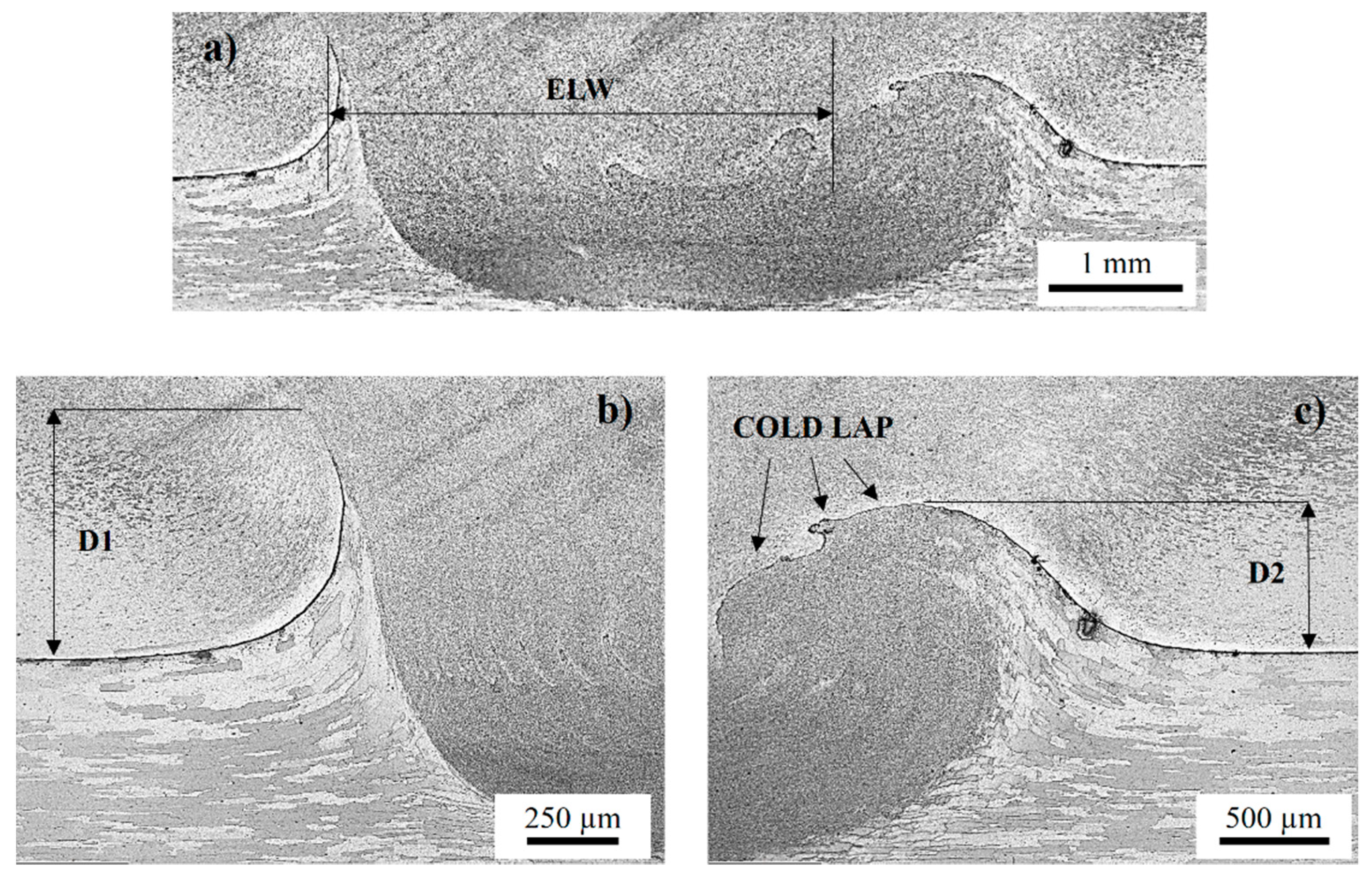
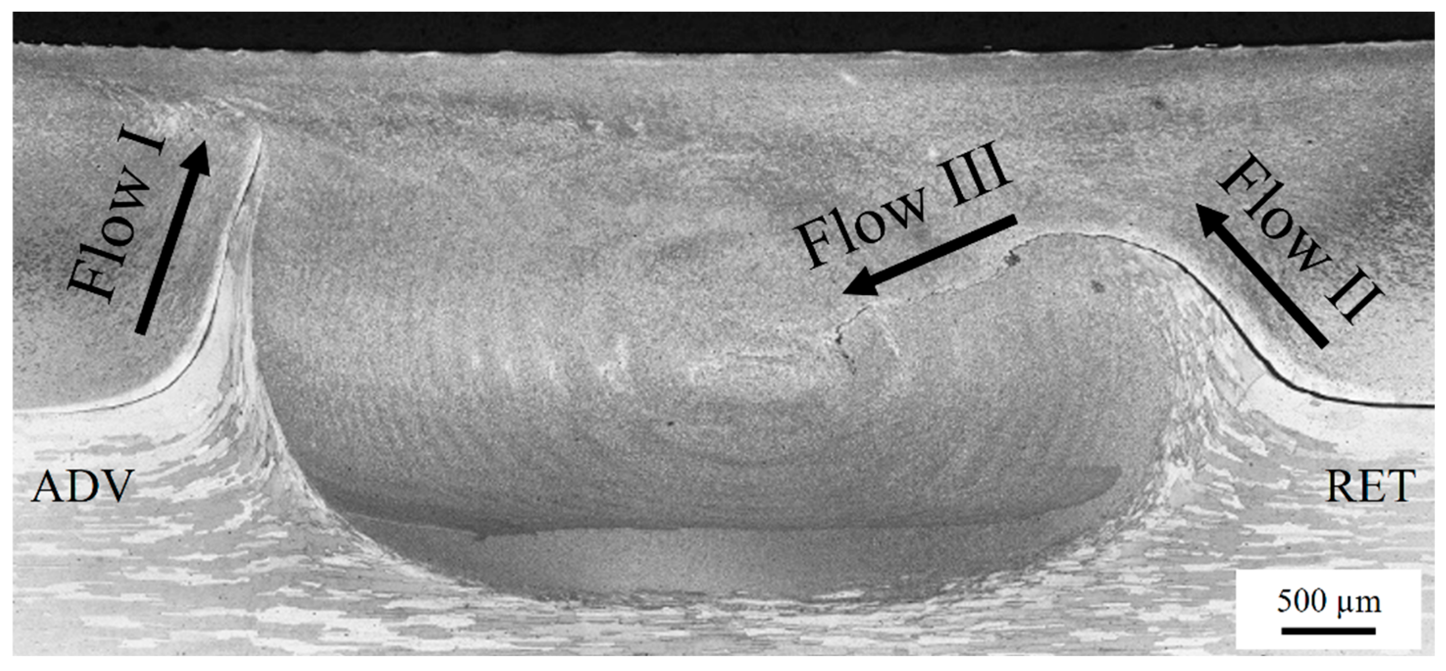
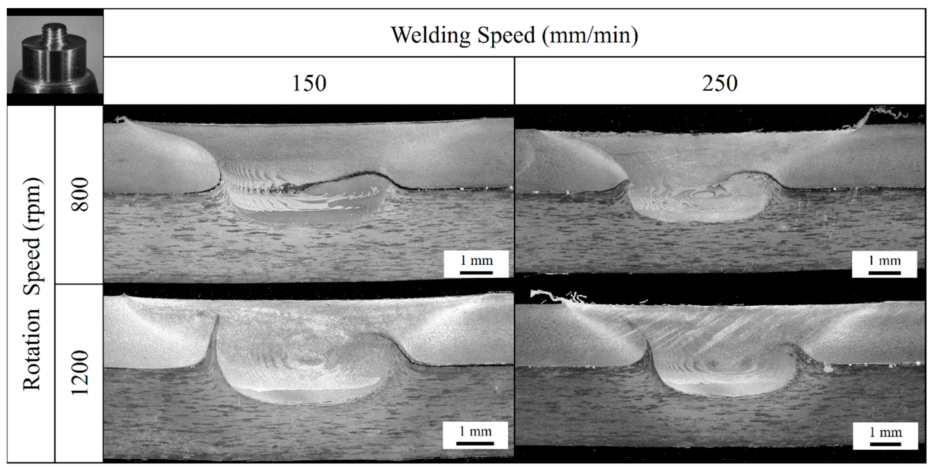
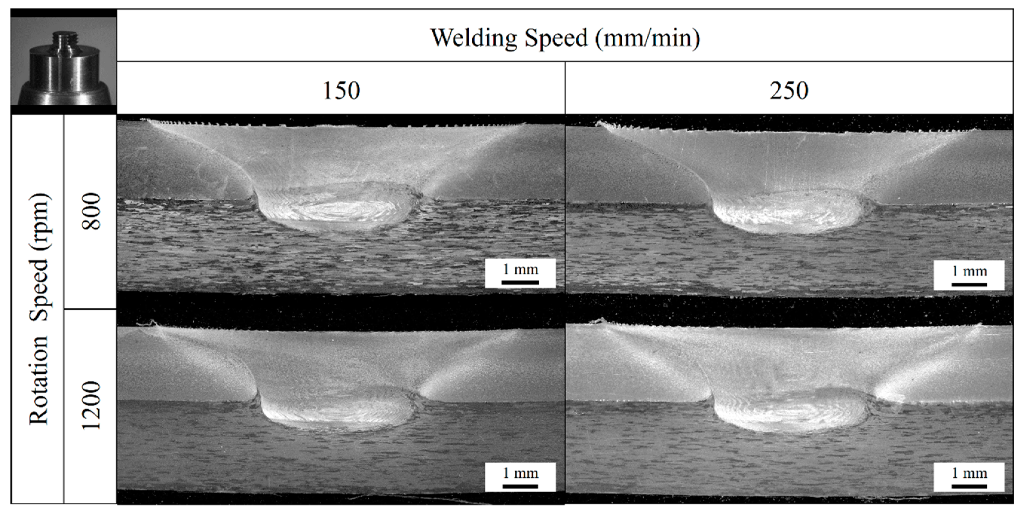
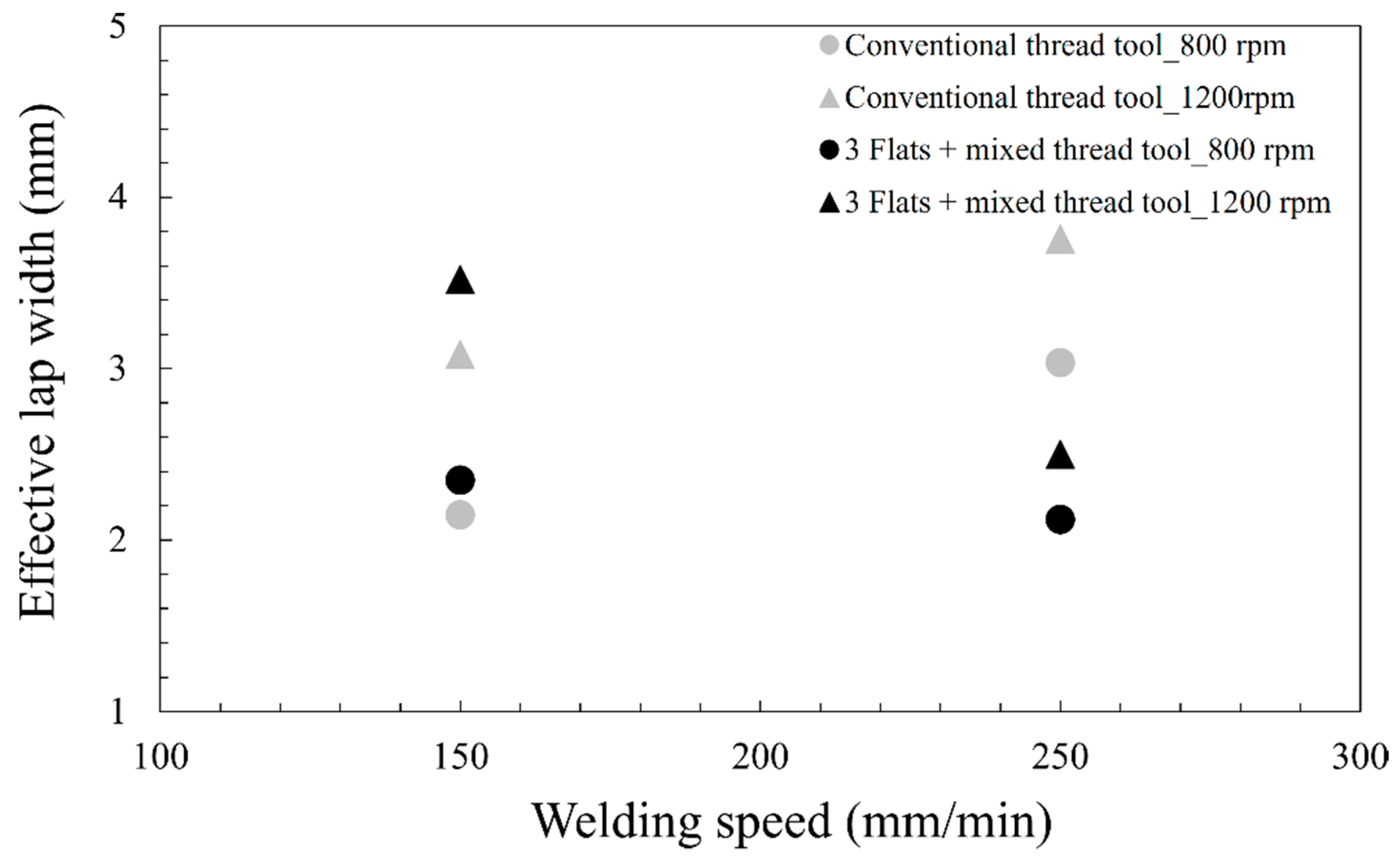
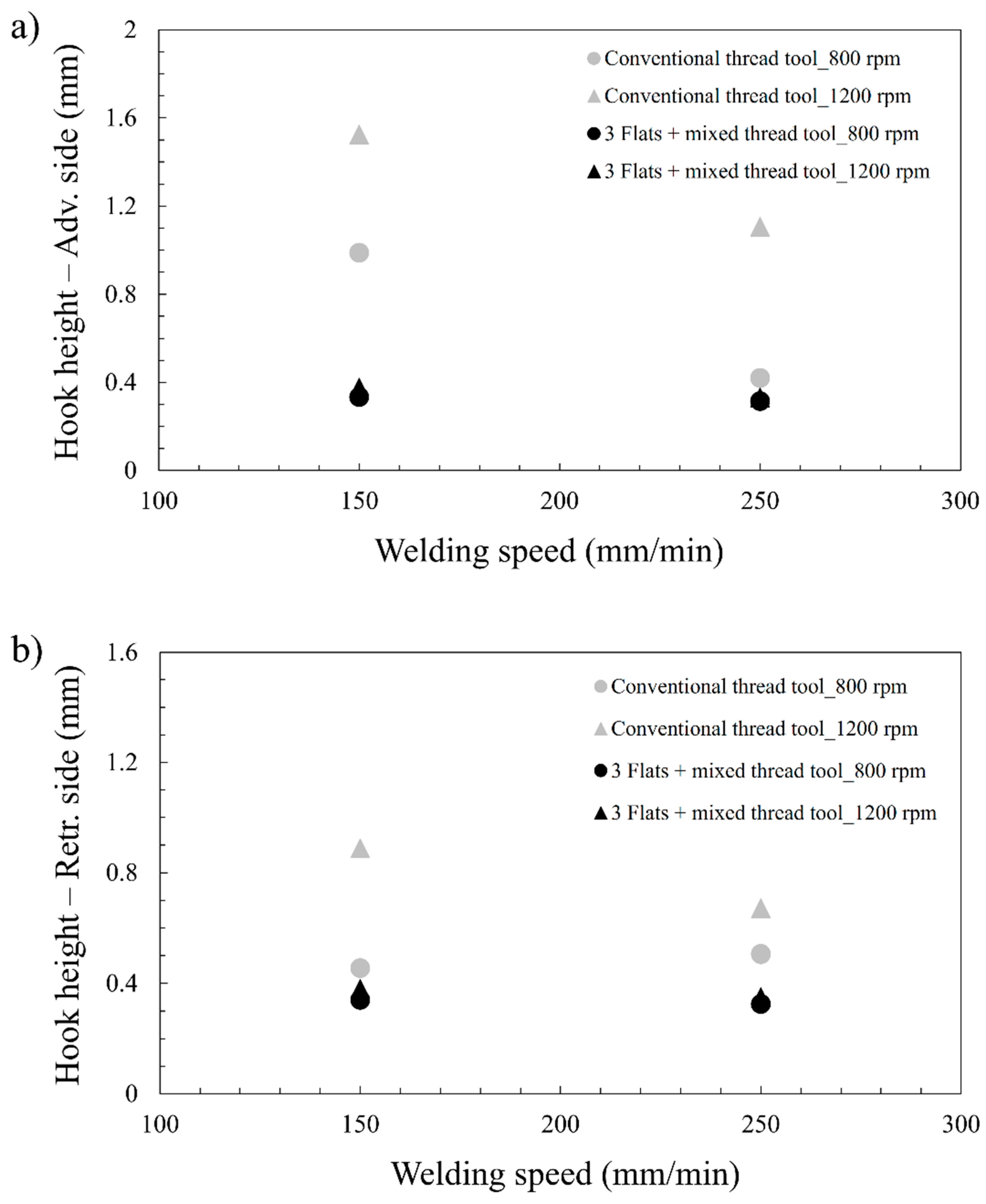
3.1. Material Flow and Weld Formation

No volumetric defects such as wormholes, cavities or cracks were found in any of the analyzed cross sections. However, as expected, the macrostructural features of the FSW lap joints were found to be different depending on the employed tool and welding parameters. Figure 2 shows a low magnification cross section of a selected FSW lap joint. The retreating and advancing sides are denoted by RET and ADV respectively. The typical microstructural zones that form FSW lap joints are the base material (BM), the heat affected zone (HAZ), the thermomechanically affected zone (TMAZ) and the weld nugget (WN). The BM is the zone that remains unaffected by the FSW process and shows the characteristic microstructures of extrusions and sheets of stringer and skin aluminium alloys, respectively. The HAZ is the microstructural zone affected by the heat generated in the FSW process and undergoes changes in the precipitate size and distribution as well as grain growth compared to the base material. The TMAZ is the zone where the material is affected by the heat and the plastic deformation. This zone is characterized by the presence of deformed and relatively coarse grains. These grains are formed mainly due to dynamic recovery as the levels of temperature and deformation suffered are not sufficient to induce any dynamic recrystallization. Finally, the WN exhibits a microstructure formed by fine equiaxed grains. This grain structure is produced by continuous dynamic recrystallization as, in contrast to the TMAZ, the temperature and plastic deformation are high enough to cause this phenomenon.
In addition to the microstructural zones, two types of joint features were observed in all the FSW lap joints: hooks and cold lap defects. An example of these joint features can be observed in Figure 3, which shows a metallographic cross-section of a FSW lap joint produced by the conventional threaded tool. The formation of these joint features results from the material flow at the faying surface between the AA2099-T83 extrusion (stringer) and the AA2060-T8E30 sheet (skin). During the welding process the plasticized material around the tool at the advancing side suffers an upward flow (labelled as flow I in Figure 4) due to the shearing effect caused by the thread of the probe. A similar effect at the retreating side also produces an upward flow (labelled as flow II in Figure 4). Both vertical flows are responsible for creating the hooks at the advancing and the retreating sides. Finally, the material flows downward (labelled as flow III in Figure 4) dragged by the action of the shoulder to fill the cavity left by the probe at the rear of the tool. The insufficient flow and mixture of the plasticized metal at the faying surface at the retreating side induces the formation of the cold lap defect.
Figure 5 and Figure 6 show the transverse cross-sections of the welds performed with the conventional threaded tool and the 3 flats + mixed thread tool respectively. In each macro-section the advancing side is on the left. It is interesting to note that volumetric defect free welds were obtained for both tools under all investigated welding parameters. However, it is clearly observed that the hook and cold lap defect features strongly vary with the welding parameters and tool geometry.
It is well known that formation of hook and cold lap defects result in a sheet thinning and in a reduction of the effective lap width (ELW) respectively, which deteriorate mechanical properties of FSW lap joints [28,29,30]. In order to quantify the size of these joint features as a function of the tool geometry and welding parameters, the ELW and the height of the hooks were measured as shown in Figure 3. Note that the ELW is defined as the horizontal distance from the tip of the hook at the advancing side to the edge of the cold lap defect at the retreating side [14].
Figure 7 depicts the ELW as a function of the welding speed for the studied tool geometries and welding parameters. The results show that at the lowest welding speed the 3 flats + mixed thread tool shows a slightly larger ELW than the conventional threaded tool. However, this result is the opposite at the highest welding speed where the conventional threaded tool presents a substantially larger ELW, for both rotational speeds. This effect can be explained due to the more extensive material flow and plasticized material mixture produced by the conventional threaded tool when using a higher welding speed.
As it can be observed in Figure 7, an increase of the welding speed results in an increment of the ELW for the conventional threaded tool. These results contrast with those obtained for the 3 flats + mixed thread tool which decreases its ELW when increasing the welding speed. These different trends are attributed to the material flow induced by the tool probe design. While the conventional threaded tool prevents the material flow labelled as III in Figure 4, the 3 flats + mixed thread tool seems to enhance it.
These results indicate the importance of using the 3 flats + mixed thread tool at low welding speed and the conventional threaded tool at high welding speed with the aim of obtaining the largest ELW possible. A large ELW is desired to guarantee optimum mechanical performance of FSW lap joints [31].
On the other hand, the increase of rotational speed allows increasing the ELW for both tools. As it can be clearly observed in Figure 5 and Figure 6, this is mainly because the cold lap defect extends over a larger horizontal distance into the weld nugget at the lower rotational speed. Then, a high rotational speed favours the material flow, plastic deformation, plasticised metal mixture and a more effective oxide dispersion at the faying surface. However, the use of higher rotational speeds also favours flow I and II resulting in an increment of the hook height in the advancing and the retreating sides when using the conventional threaded tool as can be observed in Figure 5. This effect is not observed in the welds produced by the 3 flats + mixed thread tools (Figure 6).
From the values represented in Figure 7, an increment of 30% of the ELW was estimated in average in the joints produced by the conventional threaded tool.
Figure 8 depicts hook heights at advancing and retreating sides as a function of the welding speed for the studied tool geometries and rotational speeds. Note again that hook at the retreating side is closely related to cold lap feature. As expected, larger hook heights were measured on the joints performed by the conventional threaded tool for all investigated welding parameters. The highly deformed grain orientations of AA2060-T8E30 sheet material of the TMAZ regions are indicative of the vertical material flow induced by the conventional threaded tool (flow I and II on Figure 4), which is the main formation mechanism of the hook at the advancing and the retreating sides.
For the conventional threaded tool, when increasing welding speed hook height decreases, particularly for 1200 rpm rotational speed. This can be explained by the fact that at higher welding speed the material upward flow (flow I and flow II on Figure 4) is limited due to the lower capability of shearing effect provided by the probe. For the same reason, the increase of the rotational speed increases the hook height by favouring the upward material flow in the TMAZ. Thus, in can be concluded that the hook size tends to be larger with higher rotational speeds or lower welding speeds.
In the case of the 3 flats + mixed thread tool no important differences were observed in the hook heights under the investigated welding parameters. These results may be attributed to the 3 different threads along with the 3 flats that form the probe of this tool. These geometrical features allow avoiding an excess of upward material flow that would increase the hook height at higher rotational speeds or lower welding speeds. It is important to note that this tool allows keeping the hook height short, i.e., less than 0.4 mm, under a wide range of welding parameters. This short height of the hook has been shown to increase the mechanical strength of FSW lap joints by several authors, specially the fatigue strength [24]. In addition to this, hook heights below 0.4 mm would allow to comply with the acceptance criteria B established by the new revision of the ISO25239 standard for quality requirements of FSW lap joints.
From the values represented in Figure 8, an increment of 138% of the hook heights was estimated in average in the joints produced by the conventional threaded tool.

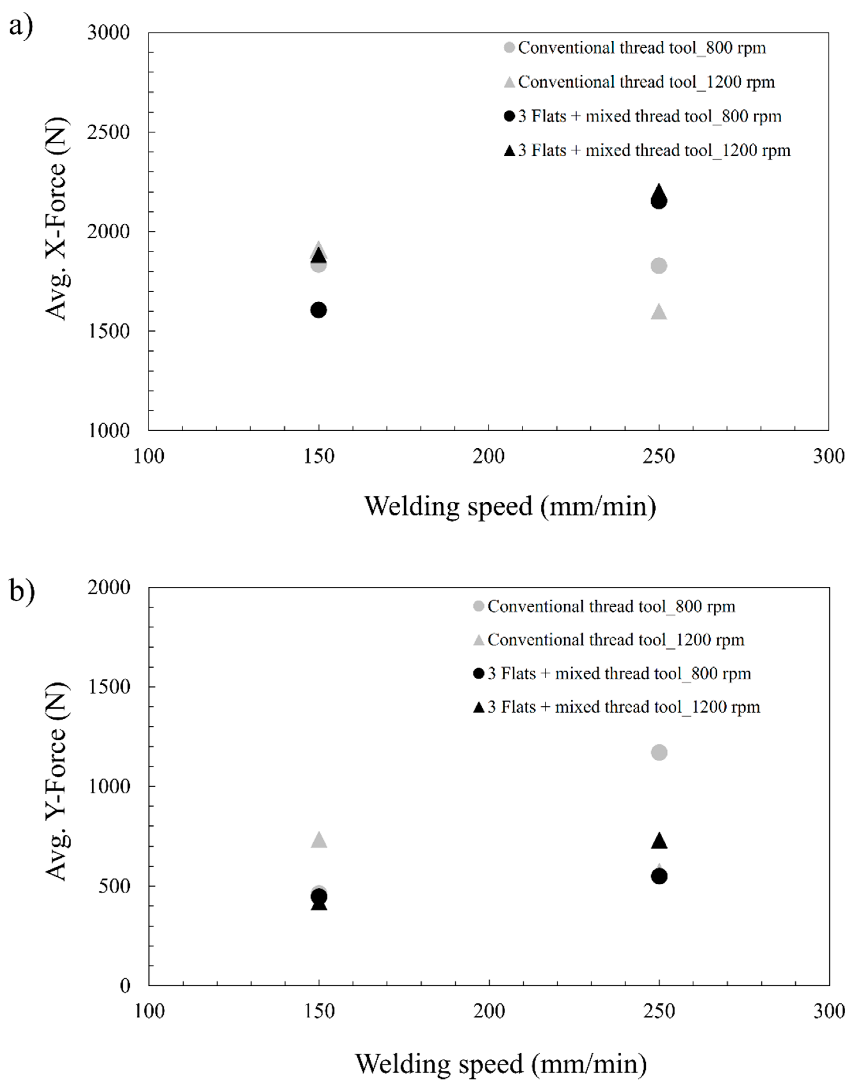
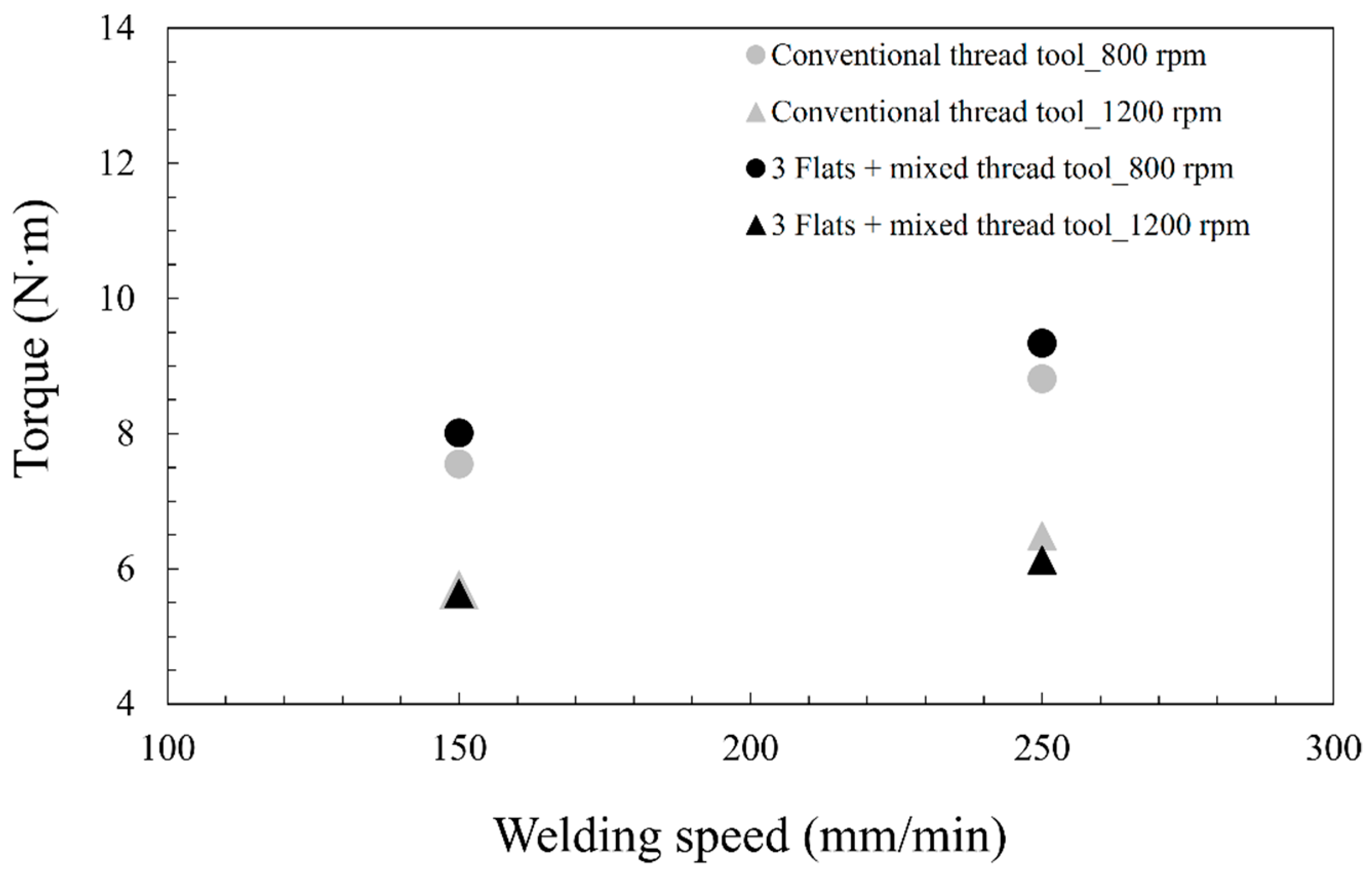
3.2. Reaction Forces during FSW Process

In-plane reaction forces (X-Force and Y-Force) are shown in Figure 9 as a function of welding speed for the studied tool geometries. The circles indicate the average reaction forces recorded for welds produced at 800 rpm of rotational speed and the triangles are for the welds produced at 1200 rpm. The general trend shows an increase in the reaction forces if higher welding speeds are used.
For the conventional threaded tool the increase of welding speed diminishes X-Force at 1200 rpm but do not produce an important change at 800 rpm. For the Y force, when increasing welding speed, the force increases at 800 rpm and slightly decreases at 1200 rpm.
In the case of the 3 flats + mixed thread tool, it can be observed that X-force and Y-force increase with increasing welding speed and increased rotational speed leads to an increase in X-force at 150 mm/min and Y-force at 250 mm/min. However, the increase of rotational speed does not affect the X-Force at 250 mm/min and Y-Force at 150 mm/min.
From these particular trends, it can be deduced that the X-force and Y-force do not have a clear trend with the welding parameters and other aspects are influencing their values [32,33]. Many authors have investigated the influence of defect formation on the in-plane reaction forces (X- force and Y-Force). Reza-E-Rabby et al. [34] reported that volumetric defects strongly affect the in-plane forces in bead on plate welds. In this regard, since there were no volumetric defects in the investigated FSW welds, the lack of a clear trend between the welding parameters and X-force and Y-force could be explained based on the influence of the hook and cold lap defect formation. The formation of these joint features alters the material flow around the tool and, in consequence, the values of X-Force and Y-force. The different hook and cold lap defect size along with different tool geometry may justify the differences in force values. Unfortunately, the relationship between the material flow and defect formation for each tool geometry cannot be well understood only with these results and further work should be done in the future to shed light on this topic.
Figure 10 depicts the torque as a function of the welding speed for the studied tool geometries and rotational speeds. A clear relationship between welding speed, rotational speed and torque for both tool geometries can be observed, i.e., the higher the welding speed, the higher the torque; and the higher the rotational speed, the lower the torque. Note, that the torque is similar for both tool geometries which implies that the shoulder size is the main factor affecting the torque and the effect by the probe features is not significant.

4. Conclusions

The effect of tool geometry and welding parameters on the properties of FSW lap joints of AA2099-T83 and AA2060-T8E30 Al-Li alloys has been studied in regard to hook and cold lap defect formation and process reaction forces. The following conclusions can be drawn from the present work:
  • Generally larger ELW values were obtained using the conventional threaded tool, although also larger hook heights were formed by this tool geometry. The increment of the ELW and the hook heights was estimated in a 30% and a 138% respectively.
  • The 3 flats + mixed thread tool showed the capability to keep the hook height values low irrespective of the employed welding parameters. Therefore, the capability to limit the vertical material flow at the faying surface of the materials has been demonstrated.
  • For both tools, a general trend was observed showing an increase of the reaction forces (X and Y) and torque values when increasing the welding speed. A clear trend showing an increase of the torque values when using lower rotational speeds and higher welding speeds was observed.
  • The reaction forces during FSW depend on the welding parameters and tool geometry, which influence the formation of hooks and cold lap defects. No clear relationship between these joint features and reaction forces was found in this investigation.
Based on these conclusions, it can be stated that the tool geometry with 3 flats + mixed thread presents clear advantages for FSW lap joint manufacturing in comparison with the conventional threaded tool design, as it is well known that smaller hook features result in an increment of the mechanical strength of FSW lap joints [21,22,23,24]. The 3 flats + mixed thread tool showed an estimated improvement of 138% in hook height while the detrimental effect in ELW was estimated in 30% in comparison with the conventional threaded tool.

Author Contributions

Conceptualization, E.A.; formal analysis, E.A. and J.V.; investigation, E.A. and J.V.; methodology, E.A.; supervision, P.Á. and I.H.; writing—original draft, E.A.; writing—review and editing, E.A., J.V., P.Á. and I.H. All authors have read and agree to the published version of the manuscript.

Funding

This work has been performed in the frame of the project ecoTECH within the AIRFRAME ITD of the Clean Sky 2 programme of the H2020. The authors acknowledge the funding received for this project under the project ID 807083 of the call H2020-IBA-CS2-GAMS-2017).

Acknowledgments

The authors want to thank Arconic and IAI for supplying the base materials used in this work.

Conflicts of Interest

The authors declare no conflict of interest.

References

  1. Starke, E.A.; Staley, J.T. Application of modern aluminum alloys to aircraft. Progress Aerosp. Sci. 1996, 32, 131–172. [Google Scholar] [CrossRef]
  2. Alexopoulos, N.D.; Gialos, A.A.; Zeimpekis, V.; Velonaki, Z.; Kashaev, N.; Riekehr, S.; Karanika, A. Laser beam welded structures for a regional aircraft: Weight, cost and carbon footprint savings. J. Manuf. Syst. 2016, 39, 38–52. [Google Scholar] [CrossRef]
  3. Sánchez Amaya, J.M.; Amaya-Vázquez, M.R.; Botana, F.J. 8—Laser welding of light metal alloys: Aluminium and titanium alloys. In Handbook of Laser Welding Technologies; Katayama, S., Ed.; Woodhead Publishing Series in Electronic and Optical Materials; Woodhead Publishing: Cambridge, UK, 2013; pp. 215–254. ISBN 978-0-85709-264-9. [Google Scholar]
  4. Gialos, A.A.; Zeimpekis, V.; Alexopoulos, N.D.; Kashaev, N.; Riekehr, S.; Karanika, A. Investigating the impact of sustainability in the production of aeronautical subscale components. J. Clean. Prod. 2018, 176, 785–799. [Google Scholar] [CrossRef]
  5. Aldanondo, E.; Arruti, E.; Alvarez, P.; Echeverria, A. Mechanical and Microstructural Properties of FSW Lap Joints. In Friction Stir Welding and Processing VII; Mishra, R., Mahoney, M.W., Sato, Y., Hovanski, Y., Verma, R., Eds.; Springer International Publishing: Cham, Switzerland, 2016; pp. 195–203. ISBN 978-3-319-48108-1. [Google Scholar]
  6. Arbegast, W.J. A flow-partitioned deformation zone model for defect formation during friction stir welding. Scr. Mater. 2008, 58, 372–376. [Google Scholar] [CrossRef] [Green Version]
  7. Guerra, M.; Schmidt, C.; McClure, J.C.; Murr, L.E.; Nunes, A.C. Flow patterns during friction stir welding. Mater. Charact. 2002, 49, 95–101. [Google Scholar] [CrossRef] [Green Version]
  8. Kashaev, N.; Ventzke, V.; Çam, G. Prospects of laser beam welding and friction stir welding processes for aluminum airframe structural applications. J. Manuf. Process. 2018, 36, 571–600. [Google Scholar] [CrossRef]
  9. Edwards, L.; Fitzpatrick, M.E.; Irving, P.E.; Sinclair, I.; Zhang, X.; Yapp, D. An Integrated Approach to the Determination and Consequences of Residual Stress on the Fatigue Performance of Welded Aircraft Structures. J. ASTM Int. 2006, 3. [Google Scholar] [CrossRef] [Green Version]
  10. Richter-Trummer, V.; Moreira, P.M.G.P.; Ribeiro, J.; de Castro, P.M.S.T. The contour method for residual stress determination applied to an AA6082-T6 friction stir butt weld. Mater. Sci. Forum 2011, 681, 177–181. [Google Scholar] [CrossRef] [Green Version]
  11. Guo, J.; Fu, H.; Pan, B.; Kang, R. Recent progress of residual stress measurement methods: A review. Chin. J. Aeronaut. 2020. [Google Scholar] [CrossRef]
  12. Zhang, H.; Wang, M.; Zhang, X.; Zhu, Z.; Yu, T.; Yang, G. Effect of Welding Speed on Defect Features and Mechanical Performance of Friction Stir Lap Welded 7B04 Aluminum Alloy. Metals 2016, 6, 87. [Google Scholar] [CrossRef] [Green Version]
  13. Chen, H.; Fu, L.; Liang, P.; Liu, F. Defect features, texture and mechanical properties of friction stir welded lap joints of 2A97 Al-Li alloy thin sheets. Mater. Charact. 2017, 125, 160–173. [Google Scholar] [CrossRef]
  14. Song, Y.; Yang, X.; Cui, L.; Hou, X.; Shen, Z.; Xu, Y. Defect features and mechanical properties of friction stir lap welded dissimilar AA2024–AA7075 aluminum alloy sheets. Mater. Des. 2014, 55, 9–18. [Google Scholar] [CrossRef]
  15. Buffa, G.; Campanile, G.; Fratini, L.; Prisco, A. Friction stir welding of lap joints: Influence of process parameters on the metallurgical and mechanical properties. Mater. Sci. Eng. A 2009, 519, 19–26. [Google Scholar] [CrossRef]
  16. Dubourg, L.; Merati, A.; Jahazi, M. Process optimisation and mechanical properties of friction stir lap welds of 7075-T6 stringers on 2024-T3 skin. Mater. Des. 2010, 31, 3324–3330. [Google Scholar] [CrossRef]
  17. Liu, H.; Hu, Y.; Peng, Y.; Dou, C.; Wang, Z. The effect of interface defect on mechanical properties and its formation mechanism in friction stir lap welded joints of aluminum alloys. J. Mater. Process. Technol. 2016, 238, 244–254. [Google Scholar] [CrossRef]
  18. Chen, G.; Li, H.; Wang, G.; Guo, Z.; Zhang, S.; Dai, Q.; Wang, X.; Zhang, G.; Shi, Q. Effects of pin thread on the in-process material flow behavior during friction stir welding: A computational fluid dynamics study. Int. J. Mach. Tools Manuf. 2018, 124, 12–21. [Google Scholar] [CrossRef]
  19. Xu, Z.; Li, Z.; Lv, Z.; Zhang, L. Effect of Welding Speed on Joint Features and Lap Shear Properties of Stationary Shoulder FSLWed Alclad 2024 Al Alloy. J. Mater. Eng. Perform. 2017, 26, 1358–1364. [Google Scholar] [CrossRef]
  20. Zhou, Z.; Yue, Y.; Ji, S.; Li, Z.; Zhang, L. Effect of rotating speed on joint morphology and lap shear properties of stationary shoulder friction stir lap welded 6061-T6 aluminum alloy. Int. J. Adv. Manuf. Technol. 2017, 88, 2135–2141. [Google Scholar] [CrossRef]
  21. Ji, S.; Li, Z.; Zhou, Z.; Wu, B. Effect of Thread and Rotating Speed on Material Flow Behavior and Mechanical Properties of Friction Stir Lap Welding Joints. J. Mater. Eng. Perform. 2017, 26, 5085–5096. [Google Scholar] [CrossRef]
  22. Liu, Z.; Zhou, Z.; Ji, S. Improving interface morphology and shear failure load of friction stir lap welding by changing material concentrated zone location. Int. J. Adv. Manuf. Technol. 2018, 95, 4013–4022. [Google Scholar] [CrossRef]
  23. ISO25239 (2011) Friction Stir Welding-Aluminium, Part 5: Quality and Inspection Requirements; The International Organization for Standardization (ISO): Geneva, Switzerland, 2011.
  24. Balakrishnan, M.; Leitão, C.; Arruti, E.; Aldanondo, E.; Rodrigues, D.M. Influence of pin imperfections on the tensile and fatigue behaviour of AA 7075-T6 friction stir lap welds. Int. J. Adv. Manuf. Technol. 2018, 97, 3129–3139. [Google Scholar] [CrossRef]
  25. Eswara Prasad, N.; Gokhale, A.A.; Wanhill, R.J.H. Aluminium–Lithium Alloys. In Aerospace Materials and Material Technologies: Volume 1: Aerospace Materials; Prasad, N.E., Wanhill, R.J.H., Eds.; Indian Institute of Metals Series; Springer: Singapore, 2017; pp. 53–72. ISBN 978-981-10-2134-3. [Google Scholar]
  26. Starke, E.A. Chapter 1—Historical Development and Present Status of Aluminum–Lithium Alloys. In Aluminum-lithium Alloys; Eswara Prasad, N., Gokhale, A.A., Wanhill, R.J.H., Eds.; Butterworth-Heinemann: Boston, MA, USA, 2014; pp. 3–26. ISBN 978-0-12-401698-9. [Google Scholar]
  27. Meng, X.; Xu, Z.; Huang, Y.; Xie, Y.; Wang, Y.; Wan, L.; Lv, Z.; Cao, J. Interface characteristic and tensile property of friction stir lap welding of dissimilar aircraft 2060-T8 and 2099-T83 Al–Li alloys. Int. J. Adv. Manuf. Technol. 2018, 94, 1253–1261. [Google Scholar] [CrossRef]
  28. Costa, M.I.; Verdera, D.; Costa, J.D.; Leitao, C.; Rodrigues, D.M. Influence of pin geometry and process parameters on friction stir lap welding of AA5754-H22 thin sheets. J. Mater. Process. Technol. 2015, 225, 385–392. [Google Scholar] [CrossRef]
  29. Li, Z.; Yue, Y.; Ji, S.; Chai, P.; Zhou, Z. Joint features and mechanical properties of friction stir lap welded alclad 2024 aluminum alloy assisted by external stationary shoulder. Mater. Des. 2016, 90, 238–247. [Google Scholar] [CrossRef]
  30. Shirazi, H.; Kheirandish, S.; Pouraliakbar, H. Employing hooking and effective sheet thickness to achieve optimum failure load in lap joints of friction stir welded AA5456 aluminum. Theor. Appl. Fract. Mech. 2020, 105, 102423. [Google Scholar] [CrossRef]
  31. Yue, Y.; Li, Z.; Ji, S.; Huang, Y.; Zhou, Z. Effect of Reverse-threaded Pin on Mechanical Properties of Friction Stir Lap Welded Alclad 2024 Aluminum Alloy. J. Mater. Sci. Technol. 2016, 32, 671–675. [Google Scholar] [CrossRef]
  32. Reza-E-Rabby, M.; Reynolds, A.P. Some effects of tool geometric features on friction stir weld response parameters. Sci. Technol. Weld. Join. 2018, 23, 575–584. [Google Scholar] [CrossRef]
  33. Reza-E-Rabby, M.; Reynolds, A.P. Effect of Tool Pin Thread Forms on Friction Stir Weldability of Different Aluminum Alloys. Procedia Eng. 2014, 90, 637–642. [Google Scholar] [CrossRef]
  34. Reza-E-Rabby, M.; Tang, W.; Reynolds, A.P. Effects of thread interruptions on tool pins in friction stir welding of AA6061. Sci. Technol. Weld. Join. 2018, 23, 114–124. [Google Scholar] [CrossRef]
Figure 1. (a) Friction stir welding (FSW) lap joint between AA2099-T83 extrusion and AA2060-T8E30 sheet and FSW tools used to produce them; (b) conventional threaded tool; (c) 3 flats + mixed thread tool; and (d) sketch showing details of the top view of the 3 flats + mixed thread tool.
Metals 10 00872 g001
Figure 2. Cross-section and microstructural zones of a friction stir welding (FSW) lap joint produced using a conventional threaded tool at 1200 rpm and 250 mm/min. Tool translation movement was forward from the shown cross-section.
Metals 10 00872 g002
Figure 3. Example of hook and cold lap defects and their characteristic measurements in a friction stir welding (FSW) lap joint: (a) effective lap width (ELW); (b) hook height at the advancing side (D1); and (c) cold lap defect and hook height at the retreating side (D2). Tool translation movement was forward from the shown cross-section.
Metals 10 00872 g003
Figure 4. Material flow produced by the conventional threaded tool operated at 1200 rpm and 150 mm/min. Tool translation movement was forward from the shown cross-section.
Metals 10 00872 g004
Figure 5. Transverse macro-sections of the friction stir welding (FSW) lap joints performed with the conventional threaded tool. The advancing side is located at the left of the image for all macro-sections. Tool translation movement was forward from the shown cross-section.
Metals 10 00872 g005
Figure 6. Transverse macro-sections of the friction stir welding (FSW) lap joints performed with the 3 flats + mixed thread tool. The advancing side is located at the left of the image for all macro-sections. Tool translation movement was forward from the shown cross-section.
Metals 10 00872 g006
Figure 7. Effective lap width (ELW on Figure 3a) as a function of welding speed for the studied tool geometries and rotational speeds.
Metals 10 00872 g007
Figure 8. (a) Hook height at the advancing side (D1 on Figure 3b) and (b) hook height at the retreating side (D2 on Figure 3c) as a function of welding speed for the studied tool geometries and rotational speeds.
Metals 10 00872 g008
Figure 9. (a) Average X-Force and (b) average Y-force as a function of welding speed for the studied tool geometries and rotational speeds.
Metals 10 00872 g009
Figure 10. Torque as a function of welding speed for the studied tool geometries and rotational speeds.
Metals 10 00872 g010
Table 1. Chemical compositions of base materials, wt.%.
AlloyAlSiFeCuMnMgZnTiAgLiZr
AA2060-T8E30Bal.0.070.073.4–4.50.1–0.50.6–1.10.3–0.50.10.05–0.50.6–0.90.05–0.15
AA2099-T83Bal.0.050.072.4–3.00.1–0.50.1–0.50.4–10.1-1.6–2.00.05–0.12
Table 2. Welding parameters used for different FSW lap joints.
Rotational Speed (rpm)Welding Speed (mm/min)
800 and 150800 and 250
1200 and 1501200 and 250

