Article

Effect of Gas Nitriding on Interface Adhesion and Surface Damage of CL60 Railway Wheels under Rolling Contact Conditions

1
College of Materials Science & Engineering, East China Jiaotong University, Nanchang 330013, China
2
Traction Power State Key Laboratory, Southwest Jiaotong University, Chengdu 610031, China
*
Authors to whom correspondence should be addressed.
Metals 2020, 10(7), 911; https://doi.org/10.3390/met10070911
Submission received: 23 June 2020 / Revised: 4 July 2020 / Accepted: 6 July 2020 / Published: 8 July 2020

Abstract

:
The influence of surface gas nitriding on wheel/rail rolling contact fatigue and wear behavior of CL60 wheel was studied on a new rolling contact fatigue/wear tester (JD-DRCF/M). The failure mechanisms of the wheel/rail surface after the gas nitriding and without gas nitriding on the wheel surface were compared and analyzed. The results show that the wheel with gas nitriding could form a dense and hard white bright layer which was approximately 25 μm thick and a diffusion layer which was approximately 70 μm thick on the wheel surface. Thus, the gas nitriding on the railway wheel not only significantly improved the wear resistance on the surface of the wheel, but also effectively reduced the wear of the rail; the results show that the material loss reduced by 58.05% and 10.77%, respectively. After the wheel surface was subjected to gas nitriding, the adhesive coefficient between the wheel/rail was reduced by 11.7% in dry conditions, and was reduced by 18.4% in water media, but even so, the wheel with gas nitriding still could keep a satisfactory adhesive coefficient between the wheel/rail systems, which can prevent the occurrence of phenomena such as wheel-slip. In short, the gas nitriding on the wheel surface can effectively reduce the wear, and improve the rolling contact fatigue resistance of the wheel/rail system. This study enlarges the application field of gas nitriding and provides a new method for the surface protection of railway wheels in heavy-duty transportation.

1. Introduction

Heavy-duty transportation has received extensive attention from railways in various countries due to its high efficiency, large capacity and low transportation cost, and it is the common trend of railway freight transportation development around the world [1,2]. Wheel/rail is the core component of railway vehicles, hence it is especially important to prevent or predict wheel–rail damage for railway service safety [3,4]. However, the development of heavy-duty railways will inevitably accompany the continuous increase in the axle load and volume of the train. Under the condition of wheel–rail rolling contact, it is easy to cause tread peeling, rail scratching, surface fatigue cracking, polygon wave grinding and even crushing and radial fracture, which seriously affects the safety of railway transportation and leads to the surge in operation and maintenance costs [5,6,7,8]. This has become a bottleneck problem that seriously affects the normal operation of heavy railways around the world and restricts their development.
Domestic and foreign scholars have carried out many studies based on surface engineering technology to improve wheel–rail tribology and rolling contact fatigue (RCF) properties [9,10]. For example, Roy and Meng et al. [11,12] used laser cladding technology to prepare a surface laser cladding layer on the surface of railway wheel and rail specimens in order to study the microstructure, residual stress and fracture toughness of wheel and rail interfaces before and after cladding treatment. Wang et al. [13,14] studied the effect of laser discrete quenching (LDQ) on the wear properties of wheel–rail materials. Their research showed that dense martensite could be obtained through laser quenching, so as to improve the material’s resistance to deformation, and significantly increase the hardness and wear resistance of wheel-rail materials, and the RCF life of wheel–rail rollers subject to LDQ was approximately two times that of untreated wheel–rail rollers. Gas nitriding is characterized by lower cost—it is an ideal heat treatment for case hardened machined components with wear surfaces. It is also ideal for parts where distortion is a concern due to tight tolerances, since distortion is not typical due to the relatively low temperatures involved in the process [15]. Jegou et al. [16] investigated the influence of nitriding potential, nitriding time and temperature on precipitation at grain boundaries and mechanical properties such as microhardness and residual stresses. They indicated that the development of residual stresses followed the principle of phase transformation kinetics during nitriding, and the kinetics was controlled by both the temperature and nitriding potential. Zhang et al. [17] performed a high cycle fatigue test for the nitrocarburized medium carbon steel for railway axle application. They suggested that three layers (oxide layer, compound layer and diffusion layer) formed on the surface of the specimen, and the results show that fatigue limits of the specimens treated in gas was improved by 120%, compared to that of the base metal. Perhaps the definition of the compound layer in their study is too imprudent, because there are also many of compounds, such as ε-Fe2–3N and γ′-Fe4N, in the diffusion layer. As Zheng et al. [18] pointed out, the diffusion layer is a compound zone and it exists below the surface layer, which dramatically improves the surface quality. Therefore, the real compound layer should be thought of in broader terms, which includes the diffusion layer. So far, there has been no report on the rolling contact fatigue or wear performance of the nitriding treatment on wheel–rail surfaces.
This paper studied the influence of the surface gas nitriding on the interface adhesion and the surface damage of a CL60 wheel under rolling contact conditions. The adhesion characteristics, surface wear and fatigue crack of the wheel–rail interfaces were analyzed under dry and water media conditions. Relevant research results can provide useful technical guidance and reference for surface engineering protection, mitigation and prevention of interface damage for heavy-duty railways.

2. Materials and Methods

2.1. Test Materials

The wheel and rail rollers were cut from the serviceable wheels (CL60, China trademark) and rails (U75V) which are applied in the heavy-haul railway in China. Then, they were machined on a lathe and no additional heat treatment was applied after machining. Their sampling position is shown in Figure 1a. Then, they were ground using emery papers with a mesh of 400–2000 to remove the mechanical harden layer, into the shape and dimensions shown in Figure 1b, and to achieve an average roughness of Ra = 0.06 μm. It should be noted that the geometric configurations of rollers were designed by means of Hertzian simulation rule, to ensure the long and short axis ratio of the contact ellipse between the wheel and rail specimens under the experimental conditions was close to the actual value [19]. The chemical composition of the wheel and rail is listed in Table 1. The wheel material consists of pearlite and ferrite, as shown in Figure 2. Moreover, to ensure that the surface was clean and avoid any oxide on the surface, all specimens were cleaned with acetone in an ultrasonic cleaning machine and air dried before the nitriding treatment.

2.2. Gas Nitriding Processes

To evaluate the effect of the surface gas nitriding on the rolling contact fatigue and wear of the wheel–rail interfaces, part of the wheel specimens were treated using an automatic nitriding furnace with a controlled atmosphere. Detail steps of the gas nitriding process used in this study are illustrated in Figure 3. Specifically, (i) firstly, the wheel specimens were placed in the furnace, then heated up to 560 °C with a heating rate of 14 °C /min, under an ammonia (NH3, 99.99% purity grade) pressure of 20 Pa; (ii) the chamber of furnace was evacuated to lower than 0.01 MPa by a rotary pump for 30 min (it is required that the ammonia decomposition rate reached 70% and the nitriding potential was around 0.7883); (iii) after that, the ammonia, with a flow rate of about 0.2 L/min, was induced into the furnace and the gas pressure was increased from 20 Pa to 0.01 MPa by controlling the vacuum valves; (iv) after this condition was maintained for 6 h under a nitriding potential of 1.6 atm−0.5, the heating of the nitriding furnace was stopped and the wheel specimens were cooled to 150 °C within the furnace under an ammonia pressure of 20 Pa; (v) finally, when the temperature was lower than 150 °C, the ammonia being transmitted into the furnace was stopped. Then, the wheel specimens were cooled to room temperature in the nitriding furnace. In addition, after the gas nitriding treatment, the nitrided specimens were re-ground by the emery paper with a mesh of 2000 and re-cleaned to remove the surface oxide layer.

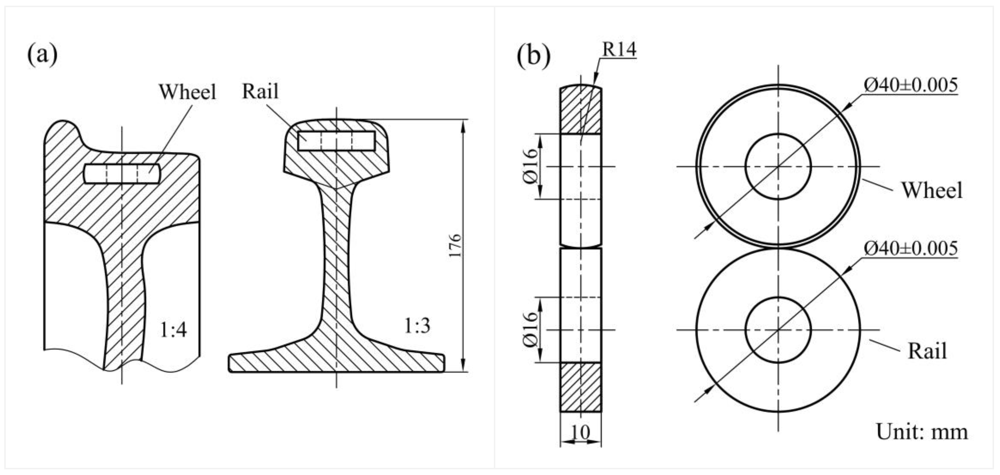
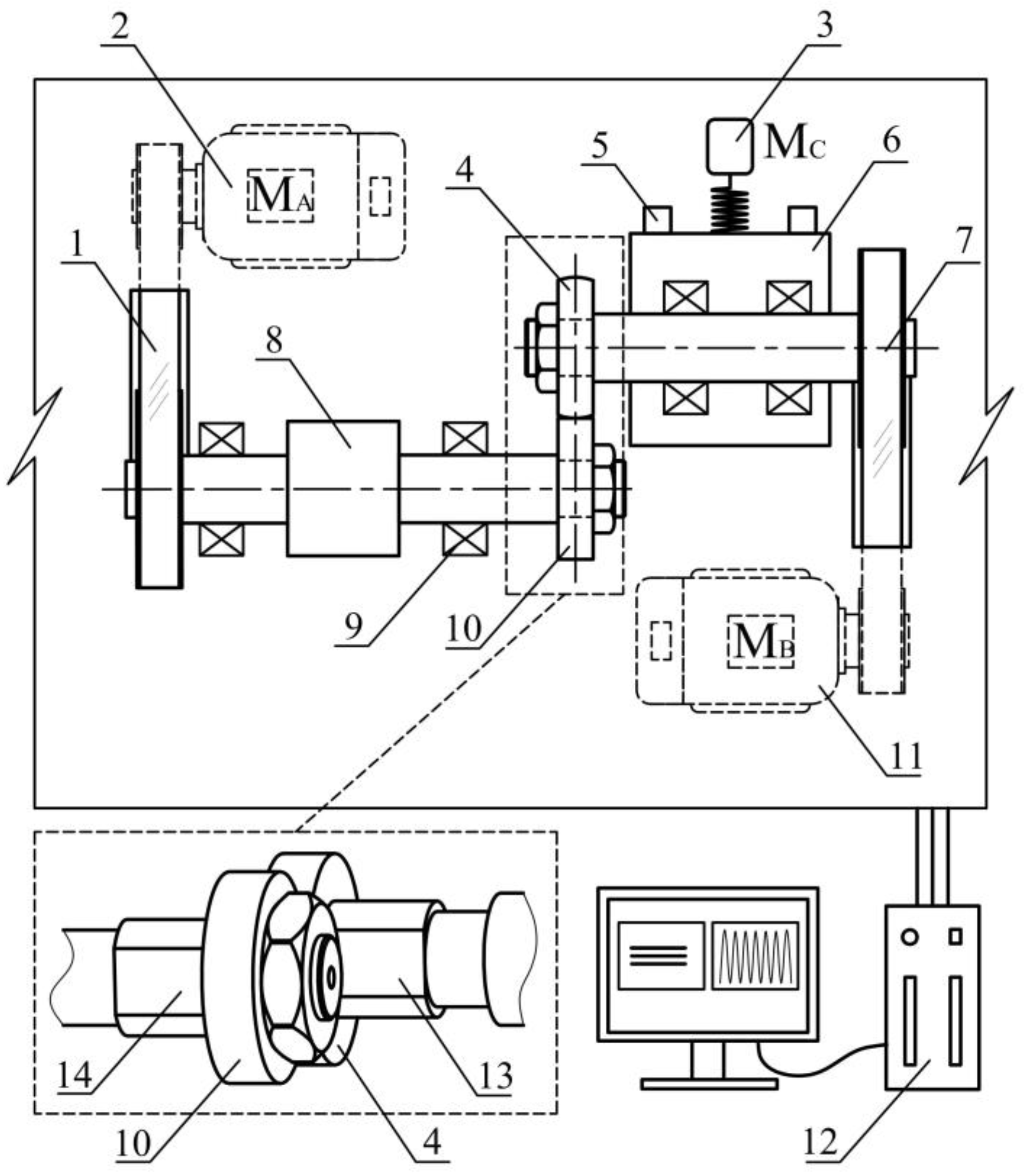
2.3. Test Method and Program

A rolling contact fatigue/wear test was conducted on a new rolling contact fatigue/wear tester (JD-DRCF/M) with the mode of double-driving. The wheel and rail rollers are driven by servo motor A and B, respectively (see Figure 4). In order to achieve the purpose of simulating the actual service angular speed and axle load conditions, the wheel specimen speed was 515 r/min, the rail specimen speed was 500 r/min, and thus the slip ratio was 3%. In addition, according to Hertz contact stress criterion, a normal force of 120 N was adopted to produce average contact pressures of about 880 MPa between the wheel/rail rollers [20]. During the rolling contact process, the friction torque of the wheel and rail rollers was recorded by a torque sensor in real time. The normal force was real-time monitored and adjusted by a loading system (including servo motor C, linear guide, load platform and load cell), which acted as the control signal feedback to the data acquisition and control system of the tester in real time.
For comparing the effect of the gas nitriding on rolling contact damage, the group with gas nitriding (nitrided wheel vs. no-nitrided rail) was used as the test group and the group without gas nitriding (no-nitrided wheel vs. no-nitrided rail) was used as the control group. The total number of cycles of a rail specimen was 2 × 10⁵ cycles. Firstly, the tests were run under dry conditions for 2 × 10³ cycles in order to determine the pre-existing wear degradation and RCF cracks in the rolling contact surface, and then the other cycles were run under wet condition, where distilled water was added to the contact interface of wheel and rail using a channel with a dripping rate of 2.1 mL/min during the test. This is a standard approach to assess RCF behavior of the rail wear and fracture on the laboratorial test machine [21].
All tests were carried out under atmospheric conditions (temperature T = 22 ± 1 °C, relative humidity, i.e., RH 50 ± 2%). The specimens were cleaned by ultrasonic bath before and after the test. After air drying, the mass loss of the specimen was weighed by an electronic balance with an accuracy of 0.1 µg, and it was repeatedly measured 5 times to reduce the measurement error. The microstructure, fatigue crack and plastic deformation were observed by optical microscope (OM, OLYMPUS BX60M, Tokyo, Japan) and the nitric acid alcohol solution (concentration: 4%) was used as the metallographic etchant. The nanoindentation tests were conducted on a Nano Indenter (Anton-Paar, NHT³, Graz, Austria) using a Berkovich diamond indenter with a constant loading/unloading rate of 20 mN/min. The surface morphologies of the worn scars were observed by a cold field emission scanning electron microscope (SEM, SU8010, Hitachi, Japan), and the element distribution on the worn surface was analyzed by X-ray energy spectroscopy (EDX, Xflash 6160, Bruker, Billerica, MA, USA). The 3D topographies of the worn scars were measured by using an optical white-light interferometer (Zygo, ZeGageTM Pro HR, Middlefield, CT, USA).

3. Results and Discussion

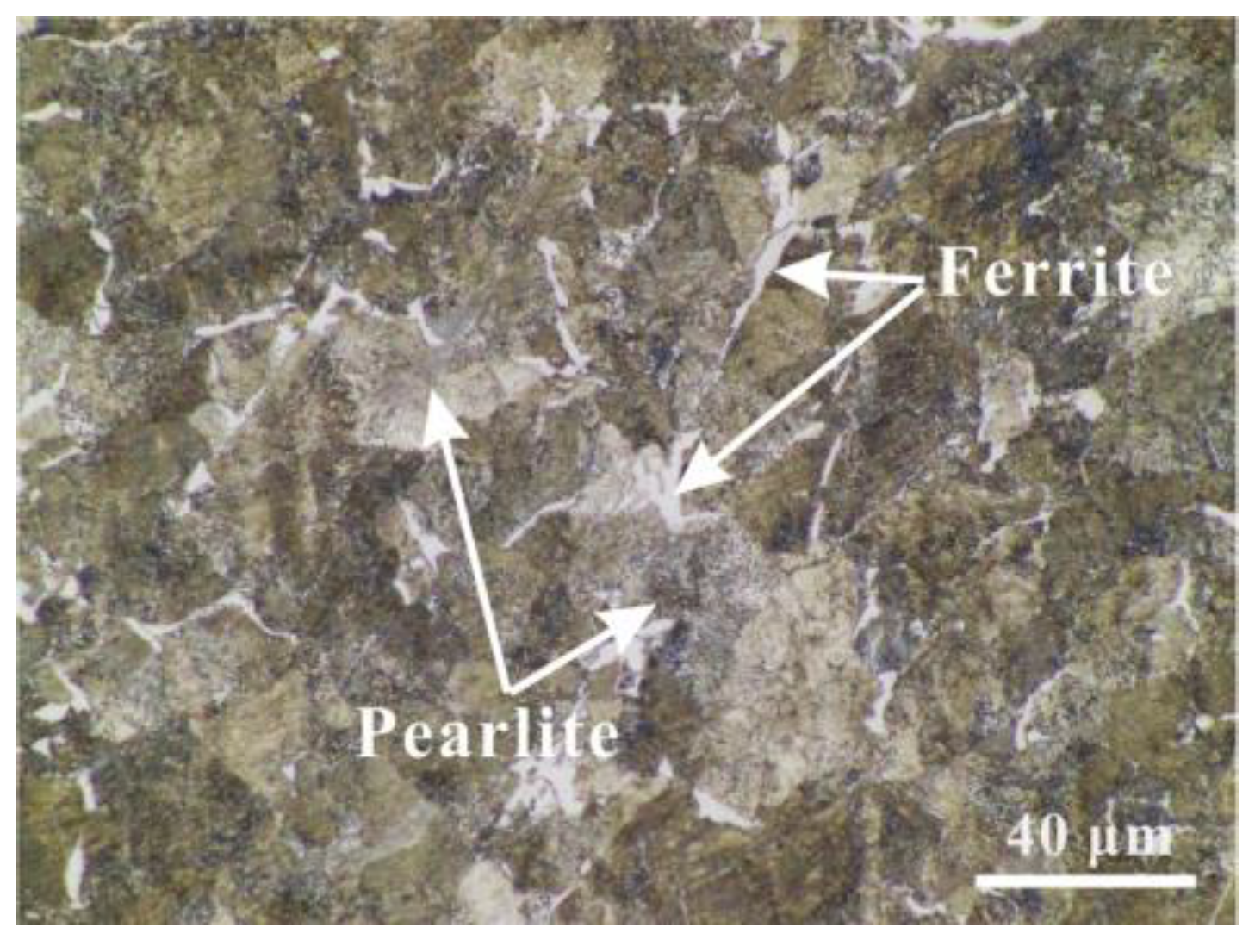
3.1. Microstructure and Mechanical Properties

Figure 5a shows the cross-sectional microstructure of the nitride layer of wheel specimen. It can be found that the nitrided specimen consists of a white bright layer, a diffusion layer and the base metal, from the surface to the inside. The white bright layer is formed on the top of the nitride layer, with a thickness of approximately 25 μm—it appears white and bright under the observation of a light microscope. Figure 5b shows the EDS line sweep curve of the N element content distributing along the depth direction. Combining this with the above metallographic analysis, it can be seen that the distribution of nitrogen was consistent with the change in microstructure, i.e., the nitrogen content in the white bright layer was the highest, and the nitrogen element in the diffusion layer gradually decreased in the depth direction. It can be explained by the fact that the iron nitrides content in this layer, such as Fe2-3N, is high. The XRD patterns of the as-received wheel material and nitrided specimens are presented in Figure 6; after the gas nitriding treatment, the surface layer contained strong diffraction peaks of γ′-Fe4N and ε-Fe2–3N phases, indicating the continuous formation of the compound layer. Beneath the white bright layer, there is a relatively thick and hard diffusion layer—its thickness is about 70 μm; the diffusion layer presented the higher phase ratio of α-Fe, γ′-Fe4N and ε-Fe2–3N, which could also be estimated from the XRD results. According to the ruler in Figure 6a, the total thickness of the compound layer is close to 100 μm.
Further, Figure 7 shows the load–displacement curves of the nitrided specimen at different distances (l) from the top surface. The indentation depth values were in the range from less than 300 nanometers to more than 520 nanometers, which were all within the nitride layer of the nitrided specimen. The hardness decreases as the depth increases. Compared with the load–displacement curves of different distances (l) from the top surface in Figure 7, the curves of the sub-surface layer (e.g., l = 20 μm) show a shallower residual depth, which means that the white bright layer has a higher elastic recovery. The indentation depth values on the top surface (i.e., l = 0 μm) was slightly larger than that of the sub-surface layer at l = 5 μm. This may be due to the fact that the surface has been mildly oxidized and polluted during the nitriding process. Even so, the average Vickers hardness of the top surface increased from ~296 HV50 to ~863 HV50 after the CL60 wheel specimen nitrided. Therefore, the nitrogen diffuses onto the surface and creates a compound zone, which observably improves the surface mechanical properties.

3.2. Analysis on Adhesion Characteristics of Wheel and Rail

Figure 8 shows the time-varying curve of the adhesion coefficient with the number of cycles during the wheel–rail specimen rolling. Before N < 2 × 10³, the rolling wear was performed in dry conditions, and the adhesion coefficient is shown in Figure 8a. It can be seen that the adhesion coefficient for the group without gas nitriding maintained a high value after about 50 cycles in the initial running-in stage, but the group with gas nitriding entered the dynamic stable stage after about 400 rolling cycles. This may be due to the fact that the white bright layer of the nitrided wheel specimen has a higher hardness than the base metal. Then, the rolling test was conducted under dropped water conditions after N > 2 × 10³, and the time-varying curve of the adhesion coefficient for the whole rolling period is shown in Figure 8b. The results show that the adhesion coefficient presented a suddenly decrease after the water medium dropped onto the wheel and rail interface (see Figure 8b). In the steady stage, the average adhesion coefficients of the group without gas nitriding and the group with gas nitriding in the dry stage were 0.61 and 0.54, respectively. However, under the water lubrication condition, the average adhesion coefficient fell from 0.61 to 0.49 for the group without gas nitriding and it fell from 0.54 to 0.40 for the group with gas nitriding, respectively. Therefore, the gas nitriding on the wheel surface could reduce the adhesion coefficients between the wheel and rail interface by 11.7% (in dry conditions) and 18.4% (in water conditions). However, the gas nitriding on the wheel surface could still maintain a relatively high value of the adhesion coefficient between the wheel and rail, which helps to avoid the occurrence of the wheel slipping on the rail.

3.3. Evaluation of Wear Amount

Comparing the wear amount of the groups with and without gas nitriding, it can be found that the wear loss of the wheel was significantly reduced after the gas nitriding, as shown in Figure 9. It is worth mentioning that the wear loss of the rail specimen which acted as the pair of tribo-pairs (without gas nitriding on the rail surface) also decreased; this is mainly because of the decrease in shear stress on the friction interface after the gas nitriding of friction pairs. As a result, the wear amount of the wheel and the rail decreased by 58.05% and 10.77%, respectively, and the total wear of the wheel–rail system decreased by approximately 30.66%. The above results show that the gas nitriding on the wheel specimen could reduce the wear loss of both the wheel and rail, and can effectively improve the wear resistance of the wheel and rail.

3.4. Wear Surface Morphology

Figure 10 shows the local topography of the surface wear area of the wheel and rail specimen. It can be seen that the obvious characteristics of fatigue delamination presented on the wear surface of wheel specimen without gas nitriding (see Figure 10a). Meanwhile, severe delamination and surface fatigue cracking were observed obviously on its counterpart (namely the worn surface of the rail specimen)—see Figure 10c. Compared with the specimen without gas nitriding, only slightly roll marks and some pits were seen on the worn surface for the wheel with gas nitriding, and no obvious delamination appeared on the worn surface (see Figure 10b). On the wheel’s counterpart, more serious peeling tracks occurred throughout the worn surface of rail specimen, but the delamination phenomenon was not particularly obvious—see Figure 10d.
According to the detection results of EDX, it can be found from Figure 11 that the atomic ratio of nitrogen to oxygen on the worn surface in Figure 10b was obviously higher than that in Figure 10a. The reason for this is that the diffusion layer plays a key role in delaying the mechanical degradations such as wear and erosion. It is well known that the relationship between wear rate and hardness is consistent with the Archard wear equation, which suggests that wear rate decreases with the increased hardness [22]. Previous studies reported that the microhardness was improved significantly from 300 to 650 HV after gas nitriding due to the formation of iron nitrides such as Fe2-3N [18]. In addition, the frictional shear stress between the wheel and rail interface was significantly restrained by the gas nitriding on their surface, and thus the wear loss of the rail specimen was also reduced. Overall, the main wear mechanism was fatigue wear and adhesive wear for the group without gas nitriding, but the wear mechanism was mainly transformed into abrasive wear and oxidative wear for the group with gas nitriding.
Figure 12 shows the 3D surface profiles and 2D cross profiles of wear scars for the rail specimen. The wear depth of the group without gas nitriding was obviously deeper than that of the group with gas nitriding on worn scars of the rail. It was further demonstrated that the gas nitriding on wheel surface can effectively alleviate the wear loss of the rail surface.

3.5. Plastic Deformation and Fatigue Crack Evaluation

Figure 13 shows the OM micrographs of plastic deformation in wear scar section of the wheel specimen (etching in 4% HNO3 in ethanol). The dry testing with 2000 cycles brought about obvious plastic deformation, and the deformation depth for the wheel without gas nitriding exceeded 90 μm in Figure 13a; however, gas nitriding can effectively resist the plastic deformation of the wheel specimen. As shown in Figure 13b, the thickness of the deformed layer was less than 30 μm. In fact, previous studies have confirmed that the sites of strain-hardening do not change significantly with different lubricants after thousands of cycles of friction. However, different types of lubricant and the order in which they are used can cause significant changes in the strain-hardening behavior of the roller [23].
The plastic deformation zone has a higher hardness and elastic modulus when subjected to long-term alternating frictional shear action (see Figure 14). With the increase in depth, the hardness and elastic modulus of nano-indentation on the cross-section of worn scars displayed similar evolution characteristics, except that of the sub-surface layer at l = 5 μm. This may be mainly due to degradation, such as the fatigue cracks and peeling tracks shown in Figure 10d, occurring on the subsurface of the worn scars. Thairon et al. [6] reported that the plastic deformation layer with higher hardness and different thickness has a greater impact on the nucleation of fatigue crack.
Figure 15 shows the fatigue crack distribution on the wear scar section for the wheel specimen. It can be found that many fatigue cracks were distributed along the rolling direction of the wheel specimen and propagated at different angles. It was indicated that the water significantly accelerates the growth of RCF cracks, since the medium trapped in the cracks helps to accelerate the propagation of cracks, which is consistent with previous studies [23]. More importantly, the gas nitriding on the wheel specimen changed the propagation behaviors of the fatigue cracks. As shown in Figure 15, the crack growth angle of the wheel without gas nitriding is larger than that of the wheel without gas nitriding, and the cracks in the wheel with gas nitriding mainly propagated in a direction parallel to the surface (see Figure 15b). Therefore, it is characterized by obvious fatigue delamination. However, the crack growth angle for the specimen without gas nitriding was quite large, and the maximum crack growth angle exceeded 22° (see Figure 15a). There is no doubt that the RCF life was markedly related to the subsurface crack propagation angle, thus a larger crack growth angle means a lower service life for the moving components.
In summary, gas nitriding on the wheel surface can effectively improve the wear resistance of the wheel and rail specimen, and obviously reduce the wear loss, both of the wheel and rail when subjected to heavy-haul service conditions. Moreover, compared with the specimen without gas nitriding, surface damage was lower, and the fatigue crack growth angle was also smaller on the wheel with gas nitriding. Therefore, the surface of the wheel with gas nitriding could effectively improve the service life of the wheel–rail system.

4. Conclusions

This research assessed the effect of gas nitriding on wheel/rail rolling contact fatigue and the surface wear behavior of a CL60 wheel. The mechanisms of wheel/rail surface damage for the wheel with gas nitriding were compared and analyzed. The main conclusions could be drawn as follows:
(1)
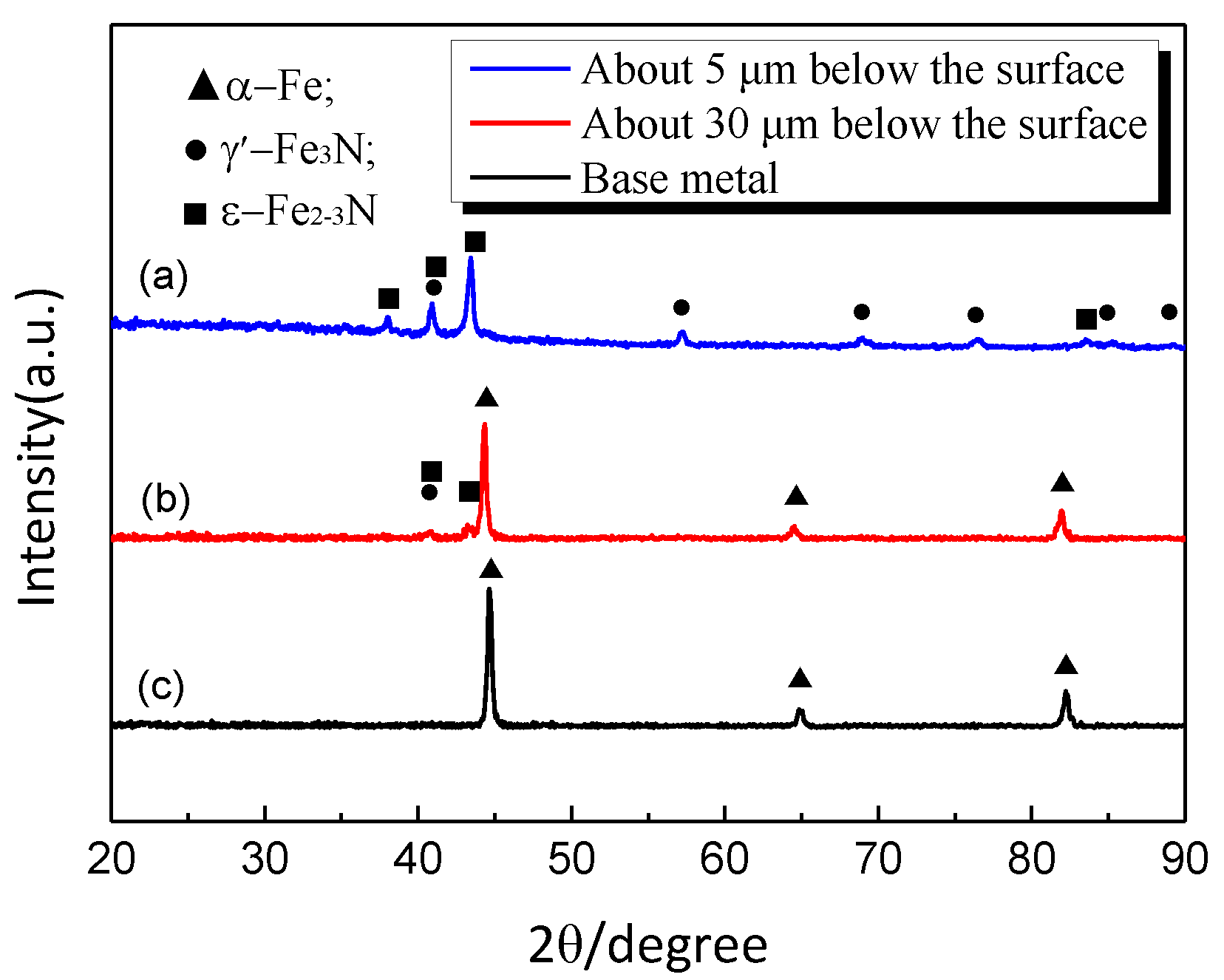
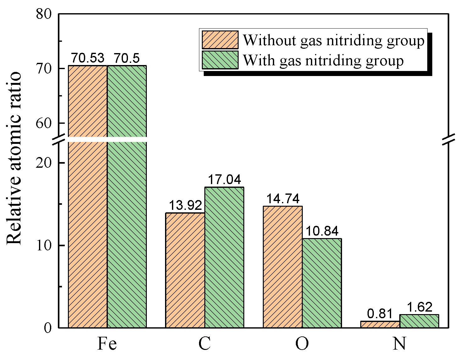
The microhardness on the nitrided surface is improved significantly due to the formation of iron nitrides such as γ′-Fe4N and ε-Fe2–3N after gas nitriding. The compound layer consists of a white bright layer with a thickness of about 20 μm and a diffusion layer with a thickness of about 70 μm. The white bright layer was not easily corroded and had good wear resistance, and the nitrogen content of the diffusion layer gradually decreased along the depth direction. The gas nitriding could increase the surface hardness of the specimen by more than 40%.
(2)
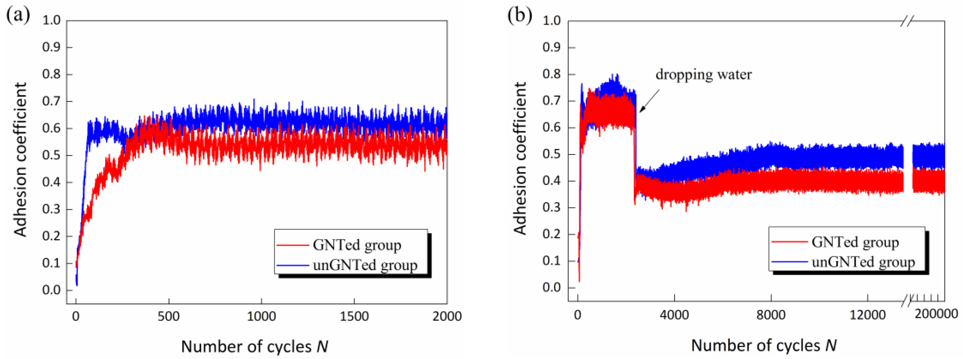
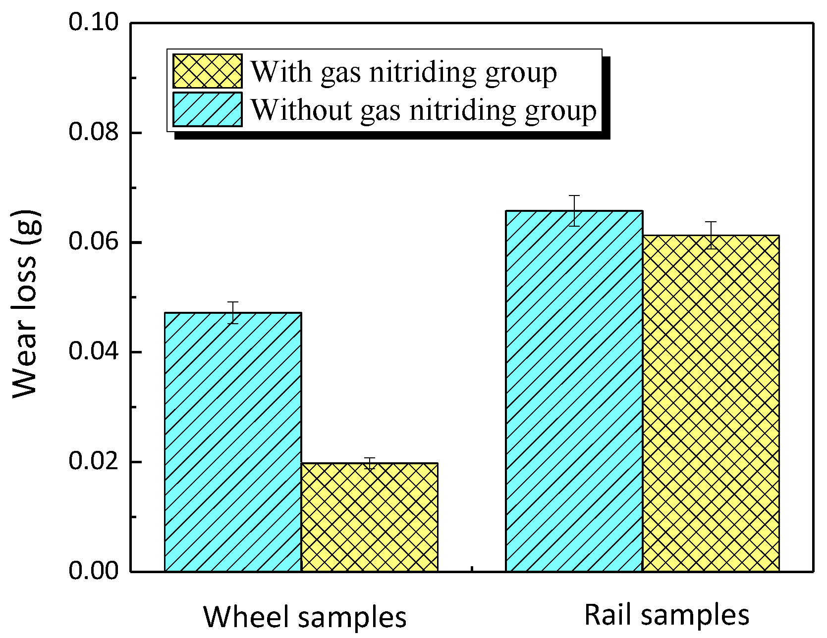
The gas nitriding on the wheel surface reduced the adhesion coefficient between the wheel and the rail by 11.7% (in dry condition) and 18.4% (in water condition). However, the wheel surface with nitriding treatment could still maintain a high adhesion coefficient between the wheel and the rail, avoiding the occurrence of wheel slippage, etc. The gas nitriding on the wheel surface not only significantly improved the wear resistance of the wheel surface, but also effectively reduced the wear amount of the rail specimen, and the loss was reduced by 58.05% and 10.77%, respectively.
(3)
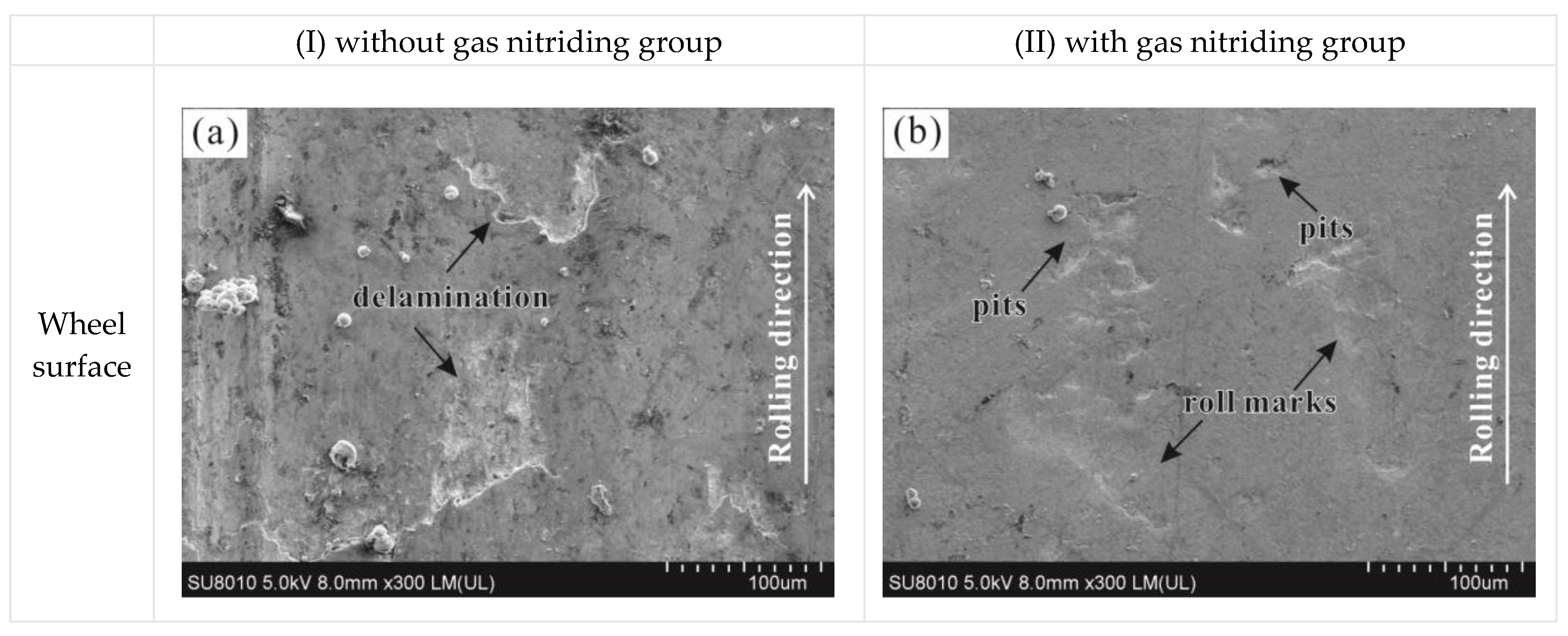
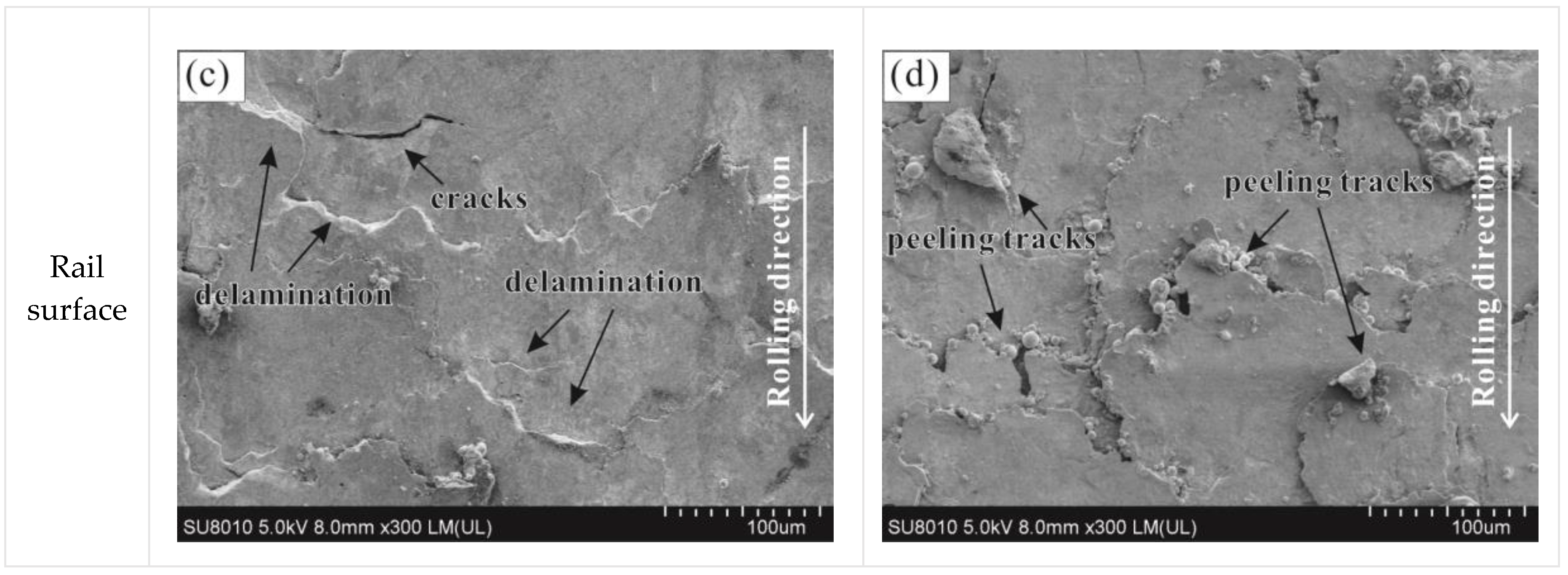
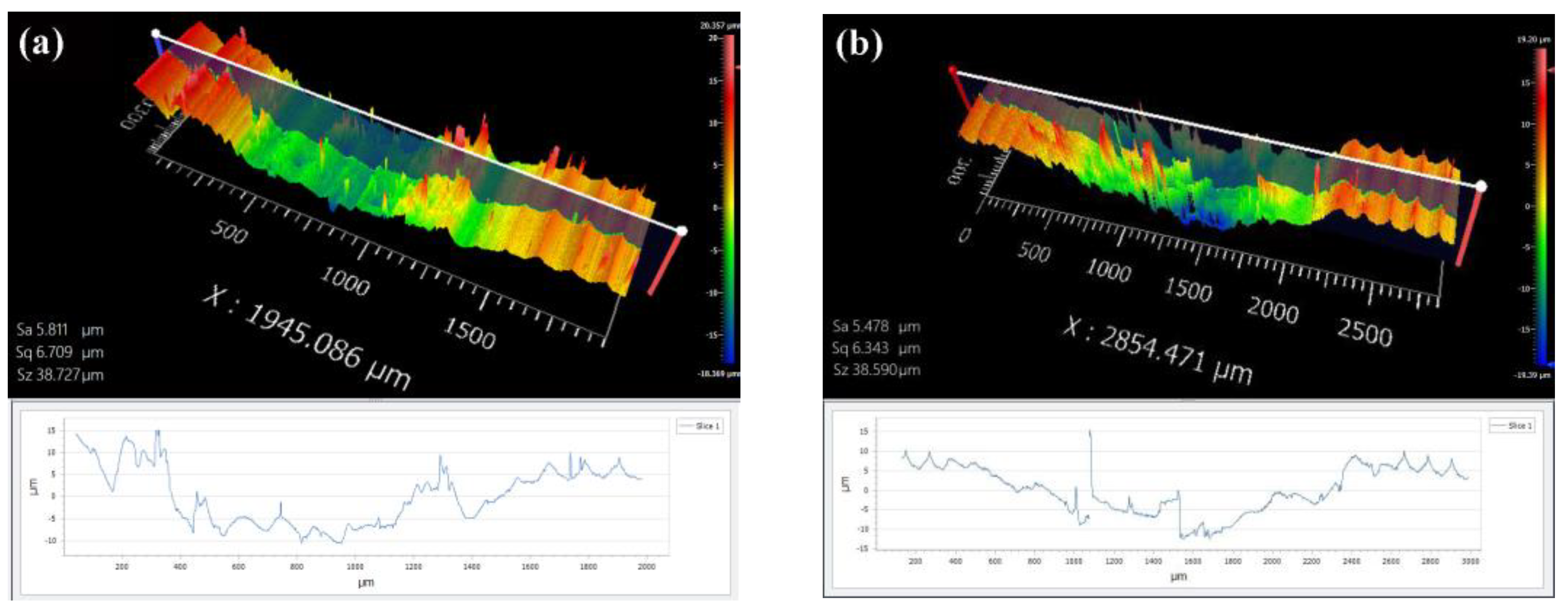
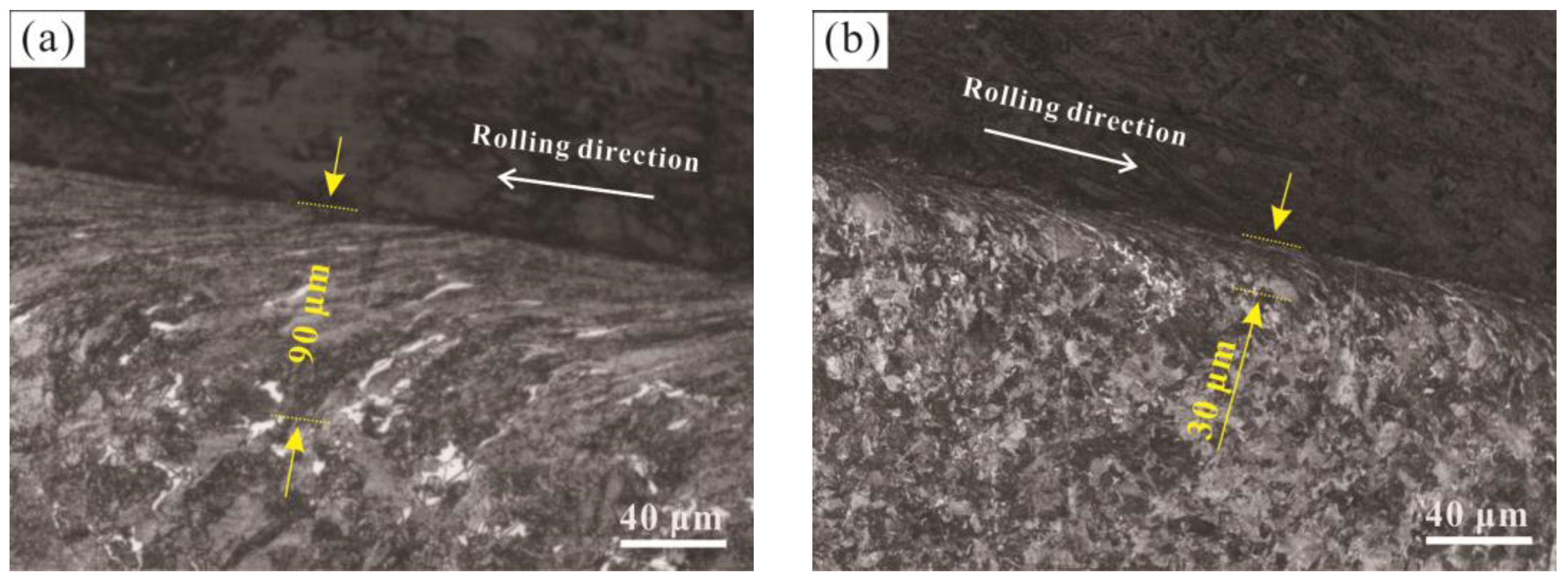
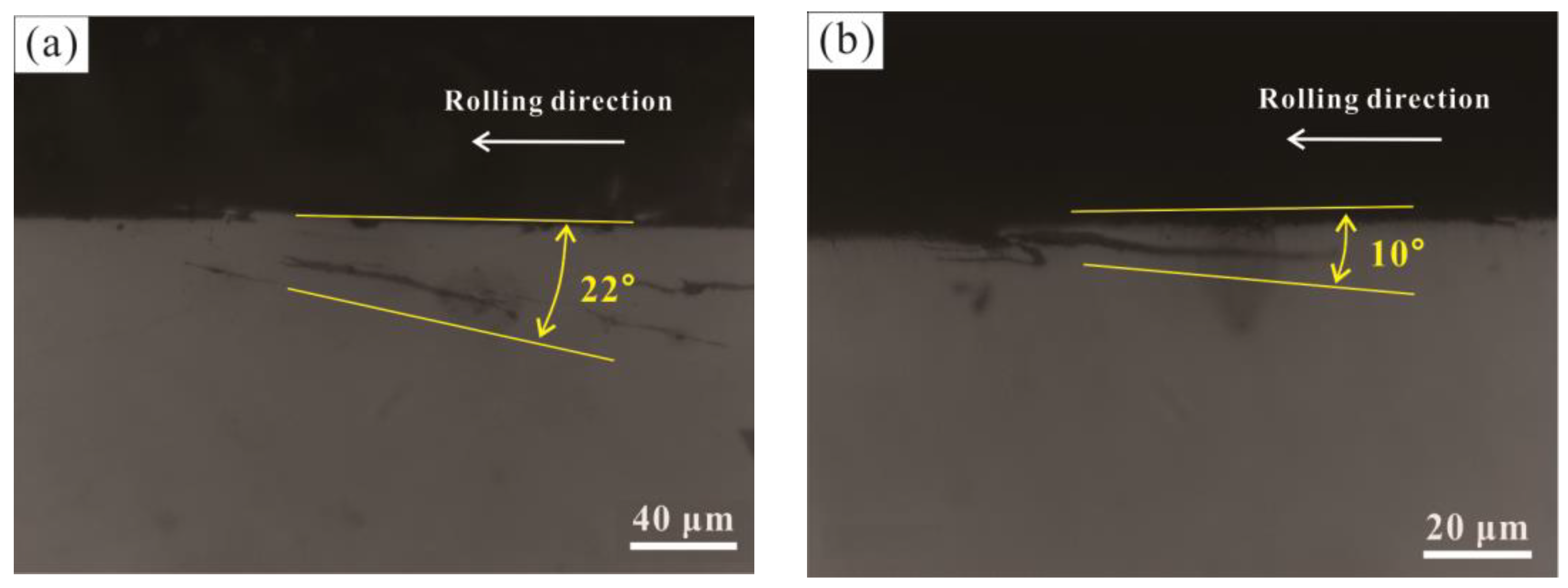
After the gas nitriding for the wheel surface, the surface peeling phenomenon was reduced, the surface damage was slight, no peeling characteristics were observed except for the indentation caused by the rolling, and the surface roughness was reduced. At the same time, the plastic deformation of the wheel surface and the crack propagation angle were reduced after gas nitriding, thus gas nitriding can effectively improve the fatigue resistance of the wheel material.

Author Contributions

Conceptualization, M.S. and G.X.; methodology, Q.W. and J.P.; software, T.Q.; validation, M.S. and J.P.; formal analysis, M.S.; investigation, Q.W.; resources, M.S.; data curation, T.Q. and K.R.; writing—original draft preparation, Q.W. and K.R.; writing—review and editing, M.S.; visualization, Q.W.; supervision, G.X.; project administration, J.P.; funding acquisition, M.S. and G.X. All authors have read and agreed to the published version of the manuscript.

Funding

This work was supported by the Open Fund of Traction Power State Key Laboratory (TPL1906), National Natural Science Foundation of China (nos. 51775503 and 51965019), Natural Science Foundation of Jiangxi Province (no. 20192BAB206026), and the China Postdoctoral Science Foundation (no. 2018T110392).

Acknowledgments

The authors thank Rui Zou from Nanchang haote material engineering equipment co. LTD for providing the nitriding treatment specimens and technical support.

Conflicts of Interest

The authors declare no conflict of interest. The funders had no role in the design of the study; in the collection, analyses, or interpretation of data; in the writing of the manuscript, or in the decision to publish the results.

References

  1. Hao, H.; Liu, Z.W.; Zhao, F.Q. An overview of energy efficiency standards in China’s transport sector. Renew. Sustain. Energy Rev. 2017, 67, 246–256. [Google Scholar] [CrossRef]
  2. Davydov, Y.; Kalikina, T.; Plyaskin, A.; Keyno, M. The Heavy Haul Train Service on the Eastern Section of the Baikal-Amur Mainline. Procedia Eng. 2017, 187, 769–774. [Google Scholar] [CrossRef]
  3. Wang, W.J.; Guo, H.M.; Du, X.; Guo, J.; Liu, Q.Y.; Zhu, M.H. Investigation on the damage mechanism and prevention of heavy-haul railway rail. Eng. Fail. Anal. 2013, 35, 206–218. [Google Scholar] [CrossRef]
  4. Lima, E.A.; Martins, T.S.; Santos, A.A. Effect of manufacturing residual stress on the fatigue life of railway wheels for heavy-haul transportation. Procedia Struct. Integr. 2019, 17, 246–253. [Google Scholar] [CrossRef]
  5. Grassie, S.; Nilsson, P.; Bjurstrom, K.; Frick, A.; Hansson, L.G. Alleviation of rolling contact fatigue on Sweden’s heavy haul railway. Wear 2002, 253, 42–53. [Google Scholar] [CrossRef]
  6. Thairon, R.; Abreu, L.E.D.; Felipe, B.; Antunes, D.S.J.A. Progression of plastic strain on heavy-haul railway rail under random pure rolling and its influence on crack initiation. Adv. Eng. Softw. 2018, 124, 10–21. [Google Scholar]
  7. Zhong, W.; Hu, J.J.; Shen, P.; Wang, C.Y.; Liu, Q.Y. Experimental investigation between rolling contact fatigue and wear of high-speed and heavy-haul railway and selection of rail material. Wear 2011, 271, 2485–2493. [Google Scholar] [CrossRef]
  8. Smitirupa, P.; Arun, K.S.; Ranjan, B. Prediction of railway wheel wear and its influence on the vehicle dynamics in a specific operating sector of Indian railways network. Wear 2018, 406, 92–104. [Google Scholar]
  9. Zhu, Y.; Yang, Y.; Mu, X.; Wang, W.J.; Yao, Z.; Yang, H.Y. Study on wear and RCF performance of repaired damage railway wheels: Assessing laser cladding to repair local defects on wheels. Wear 2019, 430, 126–136. [Google Scholar] [CrossRef]
  10. Piao, Z.Y.; Xu, B.S.; Wang, H.D.; Yu, X.X. Rolling Contact Fatigue Behavior of Thermal-Sprayed Coating: A Review. Crit. Rev. Solid State Mater. Sci. 2019. [Google Scholar] [CrossRef]
  11. Roy, T.; Paradowska, A.; Abrahams, R.; Law, M.; Mutton, P.; Soodi, M.; Yan, W.Y. Residual stress in laser cladded heavy-haul rails investigated by neutron diffraction. J. Mater. Process. Technol. 2020, 278, 116511. [Google Scholar] [CrossRef]
  12. Meng, L.; Zhao, W.F.; Hou, K.L.; Kou, D.H.; Yuan, Z.H.; Zhang, X.; Xu, J.L.; Hu, Q.W.; Wang, D.Z.; Zeng, X.Y. A comparison of microstructure and mechanical properties of laser cladding and laser-induction hybrid cladding coatings on full-scale rail. Mater. Sci. Eng. A 2019, 748, 1–15. [Google Scholar] [CrossRef]
  13. Cao, X.; Shi, L.B.; Cai, Z.B.; Liu, Q.Y.; Zhou, Z.R.; Wang, W.J. Investigation on the microstructure and damage characteristics of wheel and rail materials subject to laser dispersed quenching. Appl. Surf. Sci. 2018, 450, 468–483. [Google Scholar] [CrossRef]
  14. Su, C.R.; Shi, L.B.; Wang, W.J.; Wang, D.Z.; Cai, Z.B.; Liu, Q.Y.; Zhou, Z.R. Investigation on the rolling wear and damage properties of laser dispersed quenched rail materials treated with different ratios. Tribol. Int. 2019, 135, 488–499. [Google Scholar] [CrossRef]
  15. Zhang, G.S.; Cui, H.Z.; Zhang, H.Y.; Cheng, G.Q. Micro-porous layer generated during gas nitriding and induction quenching compound treatment affects tribological properties. Tribol. Int. 2018, 120, 226–232. [Google Scholar] [CrossRef]
  16. Jegou, S.; Barrallier, L.; Fallot, G. Gaseous nitriding behaviour of 33CrMoV12-9 steel: Evolution of the grain boundaries precipitation and influence on residual stress development. Surf. Coat. Technol. 2018, 339, 78–90. [Google Scholar] [CrossRef] [Green Version]
  17. Zhang, J.W.; Lu, L.T.; Shiozawa, K.; Zhou, W.N.; Zhang, W.H. Effects of nitrocarburizing on fatigue property of medium carbon steel in very high cycle regime. Mater. Sci. Eng. A 2011, 528, 7060–7067. [Google Scholar] [CrossRef]
  18. Zheng, C.; Liu, Y.H.; Wang, H.X.; Zhu, H.Y.; Ji, R.J.; Liu, Z.K.; Shen, Y. Research on the effect of gas nitriding treatment on the wear resistance of ball seat used in multistage fracturing. Mater. Des. 2015, 70, 45–52. [Google Scholar] [CrossRef]
  19. Wang, W.J.; Wang, H.; Wang, H.Y.; Guo, J.; Liu, Q.Y.; Zhu, M.H.; Jin, X.S. Sub-scale simulation and measurement of railroad wheel/rail adhesion under dry and wet conditions. Wear 2013, 302, 1461–1467. [Google Scholar] [CrossRef]
  20. Ding, H.H.; He, C.G.; Ma, L.; Guo, J.; Liu, Q.Y.; Wang, W.J. Wear mapping and transitions in wheel and rail materials under different contact pressure and sliding velocity conditions. Wear 2016, 352, 1–8. [Google Scholar] [CrossRef]
  21. Link, R.E.; Fletcher, D.I.; Beynon, J.H. Development of a Machine for Closely Controlled Rolling Contact Fatigue and Wear Testing. J. Test. Eval. 2000, 28, 267–275. [Google Scholar]
  22. Tjong, S.C.; Lau, K.C. Properties and abrasive wear of TiB2/Al-4% Cu composites produced by hot isostatic pressing. Compos. Sci. Technol. 1999, 59, 2005–2013. [Google Scholar] [CrossRef]
  23. Wang, W.J.; Lewis, R.; Evans, M.D.; Liu, Q.Y. Influence of different application of lubricants on wear and pre-existing rolling contact fatigue cracks of rail materials. Tribol. Lett. 2017, 65, 58–72. [Google Scholar] [CrossRef] [Green Version]
Figure 1. Sampling position (a) and scheme of geometrical contact (b) for the wheel and rail specimens.
Metals 10 00911 g001
Figure 2. Microstructure of as-received wheel material.
Metals 10 00911 g002
Figure 3. Schematic illustration of low-pressure gas nitriding used in this study.
Metals 10 00911 g003
Figure 4. Rolling–sliding wear testing apparatus: 1—synchronous belt A; 2—servo motor A; 3—servo motor C; 4—wheel specimen; 5—linear guide; 6—load platform; 7—synchronous belt B; 8—torque sensor; 9—rolling bearing; 10—rail specimen; 11—servo motor B; 12—data acquisition and control system; 13—rotation axis B; 14—rotation axis A.
Metals 10 00911 g004
Figure 5. Microstructure observation of nitrided CL60 wheel specimen (a) and distribution curve of N element by EDS line scanning (b).
Metals 10 00911 g005
Figure 6. X-ray diffraction patterns of nitrided CL60 wheel specimen at (a) the white bright layer, (b) the diffusion layer and (c) the base metal and the as-received CL60 wheel.
Metals 10 00911 g006
Figure 7. Nanoindentation load–displacement curves of the gas nitriding wheel specimen at different distances l from the top surface.
Metals 10 00911 g007
Figure 8. Time-varying curve of adhesion coefficient between the wheel and rail for the wheel with nitriding treatment and without nitriding treatment: (a) N = 2 × 10³; (b) N = 2 × 10⁵.
Metals 10 00911 g008
Figure 9. Comparison of wear loss for the wheel and rail specimens with and without gas nitriding groups: N = 2 × 10⁵.
Metals 10 00911 g009
Figure 10. SEM micrographs of wear scars on the wheel and rail wear surface: N = 2 × 10⁵; (a) and (b) wheel specimens; (c) and (d) rail specimens and their main element content.
Metals 10 00911 g010aMetals 10 00911 g010b
Figure 11. Relative atomic ratio of main element.
Metals 10 00911 g011
Figure 12. Three-dimensional surface profiles and 2D cross profiles of wear scars for the rail specimen: N = 2 × 10⁵; (a) the group without gas nitriding; (b) the group with gas nitriding.
Metals 10 00911 g012
Figure 13. Optical microscope (OM) micrographs of plastic deformation in wear scar section for the wheel specimen: N = 2 × 10³; (a) the group without gas nitriding; (b) the group with gas nitriding.
Metals 10 00911 g013
Figure 14. Nanoindentation hardness and elastic modulus values at different distances l from the worn surface corresponding to the cross-section of Figure 13b.
Metals 10 00911 g014
Figure 15. Crack behaviors in wear scar section for the wheel specimen: N = 2 × 10⁵; (a) with gas nitriding group; (b) without gas nitriding group.
Metals 10 00911 g015
Table 1. Chemical composition of wheel/rail rollers (wt%).
ElementCMnSiPS
Wheel
Rail
0.55–0.62
0.78–0.80
0.55–0.70
0.95–1.0
0.18–0.25
0.60–0.70
0.035
≤0.03
0.04
≤0.03

