The Impact of Process Factors on Creating Defects, Mainly Lustrous Carbon, during the Production of Ductile Iron Using the Lost-Foam Casting (LFC) Method


Abstract
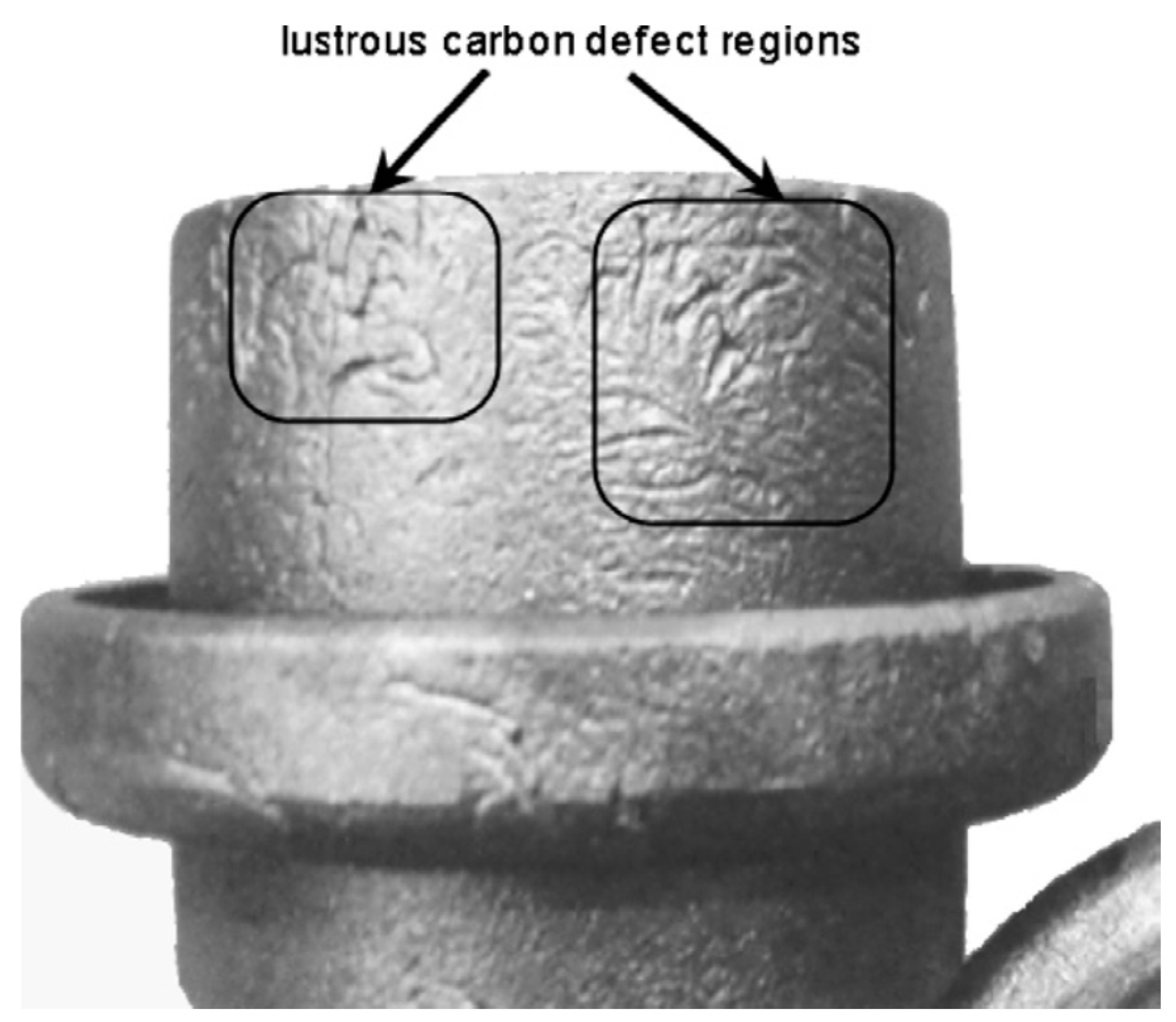
:1. Introduction
2. Materials and Methods
2.1. The Parameters Analyzed during the First Series of Melts
2.1.1. Molding Sand Matrix
2.1.2. Pouring Temperature
2.1.3. Casting Alloy Used
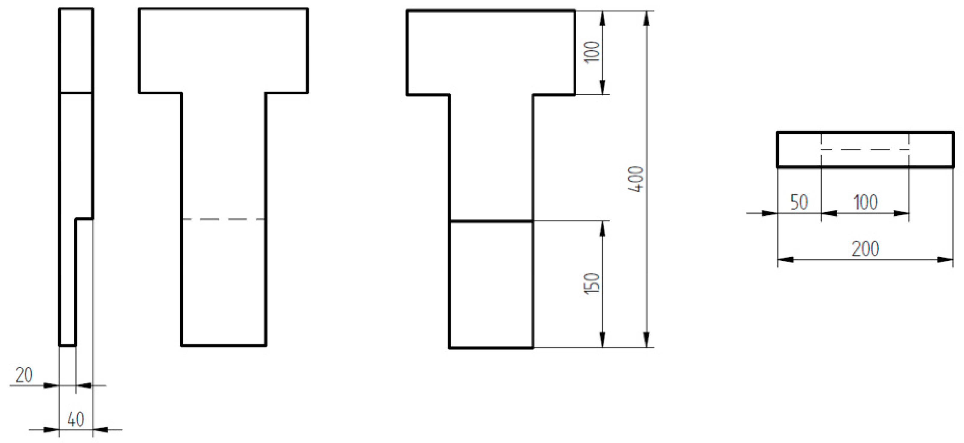
2.1.4. Molding Pattern
2.2. The Parameters Analyzed during the Second Series of Melts
2.2.1. Connection between Pattern Fragments
2.2.2. Chemical Composition of Casting Alloy
2.2.3. Pouring Temperature
2.3. The Parameters Analyzed during the Third Series of Melts
2.3.1. Pouring Temperature
2.3.2. Molding Sand
2.4. The Parameters Analyzed during the Fourth Series of Melts
2.4.1. Refractory Coating
2.4.2. Pouring Temperature
2.4.3. Chemical Composition
3. Results
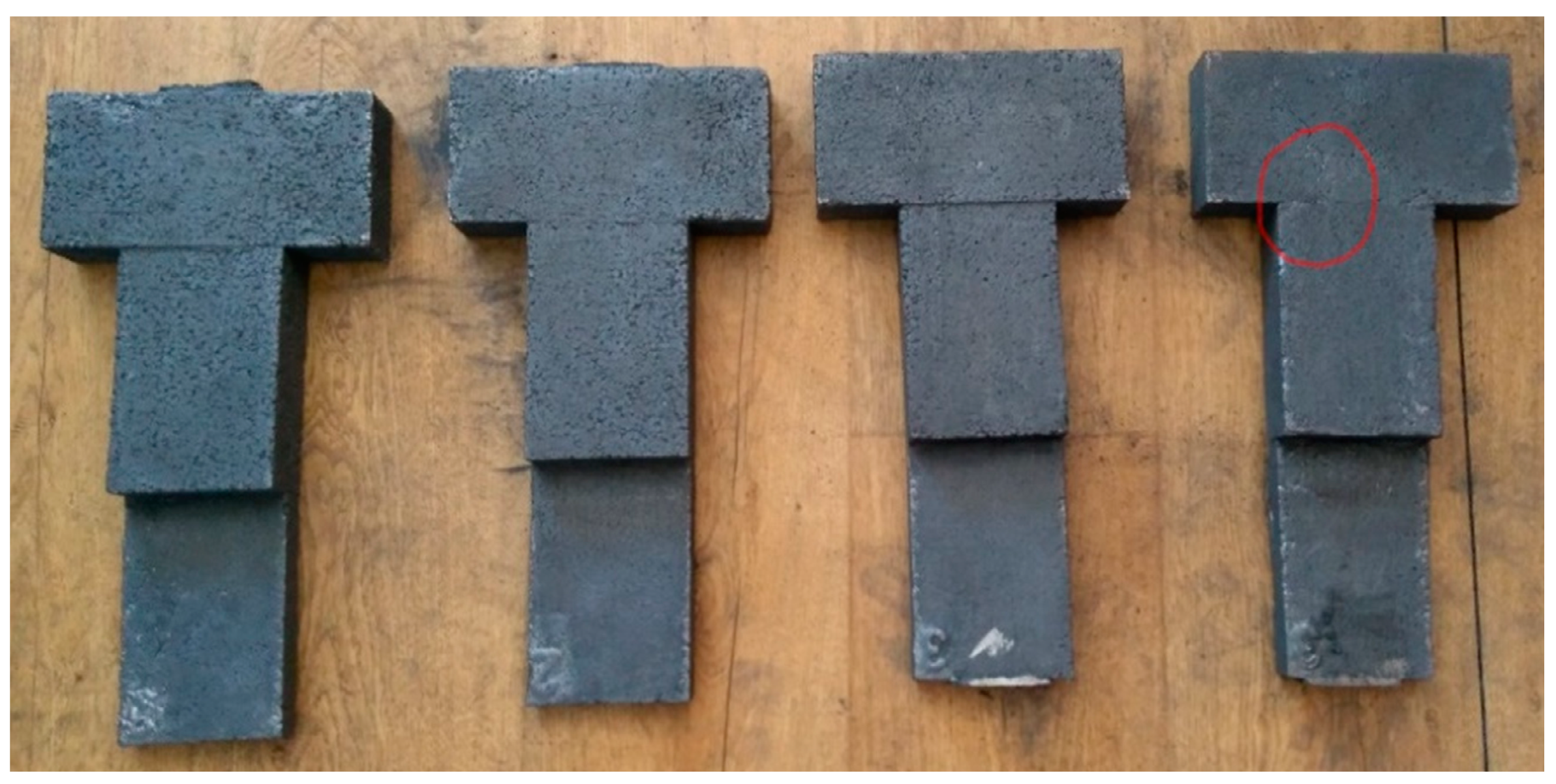
3.1. Melt 1
3.2. Melt 2
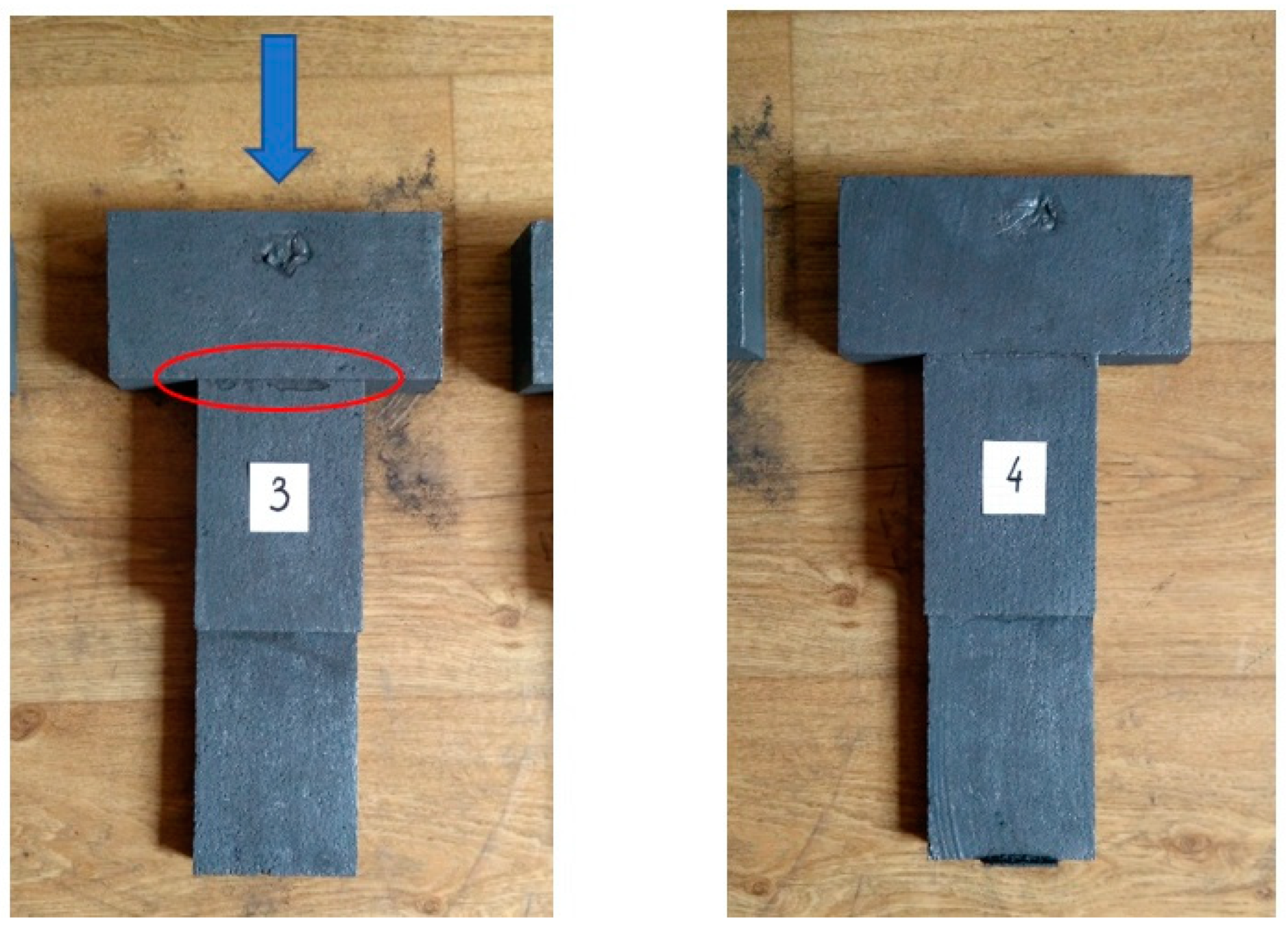
3.3. Melt 3
3.4. Melt 4
4. Discussion
5. Conclusions
Author Contributions
Funding
Conflicts of Interest
References
- Shroyer, H.F. Cavityless Casting Mold and Method of Making Same. U.S. Patent No. 2,830,343, 15 April 1958. [Google Scholar]
- Mocek, J.; Zych, J.; Krubnik, Ł. Casting of Al-Si alloys in the full-mold technology. Process conditions. Metall. Foundry Eng. 2014, 40, 161–174. [Google Scholar] [CrossRef] [Green Version]
- Pacyniak, T. Metoda Pełnej Formy. Wybrane Aspekty; Monografie Politechniki Łódzkiej: Łódź, Poland, 2013. [Google Scholar]
- Soiński, M.; Kordas, P.; Skurka, K. Trends in the Production of Castings in the World and in Poland in the XXI Century. Arch. Foundry Eng. 2016, 16, 5–10. [Google Scholar] [CrossRef]
- Campbell, J. Complete Casting Handbook, 2nd ed.; Butterworth-Heinemann: Oxford, UK, 2015. [Google Scholar]
- Khodai, M.; Mirbagheri, S.M.H. Behavior of Generated Gas in Lost Foam Casting. Int. J. Mater. Metall. Eng. 2011, 5, 151–155. [Google Scholar]
- Mocek, J.; Chojecki, A. Gas atmosphere formed in casting by full mold process. Arch. Metall. Mater. 2014, 59, 1045–1049. [Google Scholar] [CrossRef] [Green Version]
- Żuk, M.; Górka, J.; Czupryński, A.; Dojka, R. Repair Welding of Cast Iron Coated Electrodes. In Materials Science and Engineering, Proceedings of the Modern Technologies in Industrial Engineering ModTech, Sibiu, Romania, 14–17 June 2017; IOP Conference Series; IOP Publishing: Bristol, UK, 2017; Volume 227, pp. 1757–8981. [Google Scholar]
- Campbell, J.; Naro, R.L. Lustrous carbon on gray iron. In AFS Proceedings; American Foundry Society: Schaumburg, IL, USA, 2010; pp. 1–6. [Google Scholar]
- Żmudzińska, M.; Faber, J.; Perszewska, K.; Żółkiewicz, Z.; Maniowski, Z. Studying the emission of products formed during evaporation of polystyrene patterns in the lost foam process in terms of the work environment. Prace Instytutu Odlewnictwa 2011, 23–33. [Google Scholar] [CrossRef]
- Griffiths, W.D.; Ainsworth, M.J. Instability of the Liquid Metal–Pattern Interface in the Lost Foam Casting of Aluminum Alloys. Metall. Mater. Trans. A 2016, 47, 3137–3149. [Google Scholar] [CrossRef] [Green Version]
- Campbell, J.A. Hypothesis for Cast Iron Microstructures. Metall. Mater. Trans. B 2009, 40B, 786–801. [Google Scholar] [CrossRef]
- Chakherlou, T.N.; Mahdinia, Y.V.; Akbari, A. Influence of lustrous carbon defects on the fatigue life of ductile iron castings using lost foam process. Mater. Des. 2011, 32, 162–169. [Google Scholar] [CrossRef]
- Naro, R.L. Formation and control of Lustrous Carbon Surface Defects in iron and steel castings. Am Foundry Soc. Trans. 2002, 110, 815–834. [Google Scholar]
- Kaliuzhnyi, P. Influence of Sand Fluidization on Structure and Properties of Aluminum Lost Foam Casting. Arch. Foundry Eng. 2020, 1, 122–126. [Google Scholar]
- Mirbagheri, S.M.H.; Serajzadeh, S.; Varahram, N.; Davami, P. Patterning of foam degradation in lost foam casting process. Mater. Des. 2006, 27, 115–124. [Google Scholar] [CrossRef]
- Azimi, H.R.; Rezaei, M.; Abbasi, F. Thermo-oxidative degradation of MMA–St copolymer and EPS lost foams: Kinetics study. Thermochim. Acta 2009, 488, 43–48. [Google Scholar] [CrossRef]
- Shayegh, J.; Hossainpour, S.; Rezaei, M.; Charchi, A. Developing a new 2D pattern for heat transfer and foam degradation in EPS lost foamcasting (LFC) process. Int. Commun. Heat Mass. Transf. 2010, 37, 1396–1402. [Google Scholar] [CrossRef]
- Liu, X.J.; Bhavnani, S.H.; Overfelt, R.A. Simulation of EPS foam decomposition in the lost foam casting process. J. Mater. Process. Tech. 2007, 182, 333–342. [Google Scholar] [CrossRef]
- Pacyniak, T.; Kaczorowski, R. Badanie własności pokryć ogniotrwałych nanoszonych na patterne polistyrenowe, stosowane przy wytwarzaniu odlewów metodą lostfoam. Arch. Foundry 2003, 3, 147–156. [Google Scholar]
- Campbell, J. Leakage Defects via Bubble Trails in Grey Iron Castings. Int. J. Met. 2007, 1, 7–16. [Google Scholar] [CrossRef]
- Naro, R.L. Battling the Elusive Lustrous Carbon Defect. Mod. Cast. 2003, 5, 32–35. [Google Scholar]


| DI Grade | C | Si | Mn | S | P | Mg | CE | Sc |
|---|---|---|---|---|---|---|---|---|
| EN-GJS 400-15 | 3.69 | 2.29 | 0.16 | 0.006 | 0.046 | 0.054 | 4.407 | 1.041 |
| DI Grade | C | Si | Mn | S | P | Mg | CE | Sc |
|---|---|---|---|---|---|---|---|---|
| EN-GJS 400-15 | 3.41 | 2.04 | 0.18 | 0.008 | 0.046 | 0.035 | 4.06 | 0.945 |
| DI Grade | C | Si | Mn | S | P | Mg | CE | Sc |
|---|---|---|---|---|---|---|---|---|
| EN-GJS 700-2 | 3.41 | 2.57 | 0.47 | 0.010 | 0.052 | 0.053 | 4.215 | 0.987 |
| DI grade | C | Si | Mn | S | P | Mg | CE | Sc |
|---|---|---|---|---|---|---|---|---|
| EN-GJS 400-15 | 3.43 | 2.30 | 0.20 | 0.013 | 0.081 | 0.053 | 4.175 | 0.976 |
© 2020 by the authors. Licensee MDPI, Basel, Switzerland. This article is an open access article distributed under the terms and conditions of the Creative Commons Attribution (CC BY) license (http://creativecommons.org/licenses/by/4.0/).
Share and Cite
Jezierski, J.; Jureczko, M.; Dojka, R. The Impact of Process Factors on Creating Defects, Mainly Lustrous Carbon, during the Production of Ductile Iron Using the Lost-Foam Casting (LFC) Method. Metals 2020, 10, 1022. https://doi.org/10.3390/met10081022
Jezierski J, Jureczko M, Dojka R. The Impact of Process Factors on Creating Defects, Mainly Lustrous Carbon, during the Production of Ductile Iron Using the Lost-Foam Casting (LFC) Method. Metals. 2020; 10(8):1022. https://doi.org/10.3390/met10081022
Chicago/Turabian StyleJezierski, Jan, Michał Jureczko, and Rafał Dojka. 2020. "The Impact of Process Factors on Creating Defects, Mainly Lustrous Carbon, during the Production of Ductile Iron Using the Lost-Foam Casting (LFC) Method" Metals 10, no. 8: 1022. https://doi.org/10.3390/met10081022