Article

Ultrasonic and Conventional Fatigue Endurance of Aeronautical Aluminum Alloy 7075-T6, with Artificial and Induced Pre-Corrosion

by
Ishvari F. Zuñiga Tello
1,
Marijana Milković
2,
Gonzalo M. Domínguez Almaraz
1,* and
Nenad Gubeljak
2
1
Faculty of Mechanical Engineering, University of Michoacan (UMSNH), Santiago Tapia 403, Morelia 58000, Mexico
2
Faculty of Mechanical Engineering, University of Maribor, Smetanova 17, 2000 Maribor, Slovenia
*
Author to whom correspondence should be addressed.
Metals 2020, 10(8), 1033; https://doi.org/10.3390/met10081033
Submission received: 4 July 2020 / Revised: 20 July 2020 / Accepted: 24 July 2020 / Published: 1 August 2020
(This article belongs to the Special Issue Structure and Properties of Aluminium Alloys)

Abstract

:
Ultrasonic and conventional fatigue tests were carried out on the AISI-SAE AA7075-T6 aluminum alloy, in order to evaluate the effect of artificial and induced pre-corrosion. Artificial pre-corrosion was obtained by two hemispherical pitting holes of 500-μm diameter at the specimen neck section, machined following the longitudinal or transverse direction of the testing specimen. Induced pre-corrosion was achieved using the international standard ESA ECSS-Q-ST-70-37C of the European Space Agency. Specimens were tested under ultrasonic fatigue technique at frequency of 20 kHz and under conventional fatigue at frequency of 20 Hz. The two applied load ratios were: R = −1 in ultrasonic fatigue tests and R = 0.1 in conventional fatigue tests. The main results were the effects of artificial and induced pre-corrosion on the fatigue endurance, together with the surface roughness modification after the conventional fatigue tests. Crack initiation and propagation were analyzed and numeric models were constructed to investigate the stress concentration associated with pre-corrosion pits, together with the evaluation of the stress intensity factor in mode I from crack initiation to fracture. Finally, the stress intensity factor range threshold ΔKTH was obtained for the base material and specimens with two hemispherical pits in transverse direction.

1. Introduction

One of the most versatile metal used in industrial applications is aluminum and its alloys; it is the second widely produced metal after steel. Particularly, its alloys are often used in modern industries: more than 40% of aerospace and aeronautical parts are made of these alloys nowadays [1,2,3,4]. Frequently, such industrial applications imply a combination of mechanical loading and corrosion, which leads to stress concentration and failure of the material. Pitting corrosion is one of the most damaging effect on materials, difficult to predict in order to avoid damage and failure in industrial components [5,6,7,8,9]. In previous numeric investigations [10], it was found that orientation of the corrosion pits regarding the applied load plays a significant role on the stress concentration factors. An important number of studies has been focused to understanding how cracks initiate and propagate in materials influenced by external factors, such as corrosion pitting, surface conditions, temperature and others [10,11,12,13]. A main motivation to carry out this research work is that no studies have been developed concerning the effect of pre-corrosion on the fatigue endurance, under conventional and ultrasonic tests, on this aeronautical aluminum alloy. Concerning surface roughness, fatigue life has been studied in a carbon steel, showing that this superficial parameter influences fatigue life only during crack initiation stage [14]; others investigations [15,16], have referred that fatigue life is reduced with the increase of roughness. In this study, the roughness has been registered before and after the conventional fatigue tests, in order to record its variation.
On the other hand, several studies have pointed out the correlation between pitting corrosion and the reduction of fatigue life [17,18,19,20], taking the maximum or the average pit size as the initial crack size; nevertheless, no consideration of pits interactions has been considered inducing high values of stress concentrations factors. In this study, a numeric model reproducing two pits on the specimen surface is developed in order to investigate the increase of stress concentrations factors associated with its orientation. Fatigue endurance of pitting metals can be improved applying shoot peening, which induces compression residual stress [21,22].

2. Materials and Methods

The chemical composition (% in weight) and the main mechanical properties of AA7075-T6 aluminum alloy are listed in Table 1 and Table 2, respectively. In order to obtain experimentally some mechanical properties as yield stress and ultimate tensile stress of this aluminum alloy (Table 2), tests were conducted on universal testing machine Instron 1255 (Instron, Norwood, NY, USA) on 4 specimens (cold-rolled Al7075-T6 sheet, tension applied parallel to the rolling direction of the sheet) of non-standard dimensions and at room temperature.
The specimens used in ultrasonic fatigue test were machined from an AA7075-T6 plate, its dimensions were determined by modal numeric analysis in order to fit the resonance condition: the natural frequency of vibration in longitudinal direction close to frequency of excitation source (20 kHz ± 300 Hz). The dimensions (mm) are shown in Figure 1a for the ultrasonic specimen and, Figure 1b for the conventional specimen. In Figure 2 is depicted the result of modal analysis: 19,929 Hz of natural frequency for ultrasonic specimen with dimensions presented in Figure 1a, using the mechanical properties of Table 2: density, Young’s modulus and Poisson ratio. Ansys 19-R1 was used with 12,120 elements, 55,753 nodes and a fixed support at the specimen’s end as boundary condition.
Specimens used for conventional fatigue tests present similar dimensions of the previous ultrasonic specimens, slightly modifications were introduced, such as: a machined rope at the extremes of specimen in order to fix it to the testing machine, Figure 1b.

Experimental Set Up

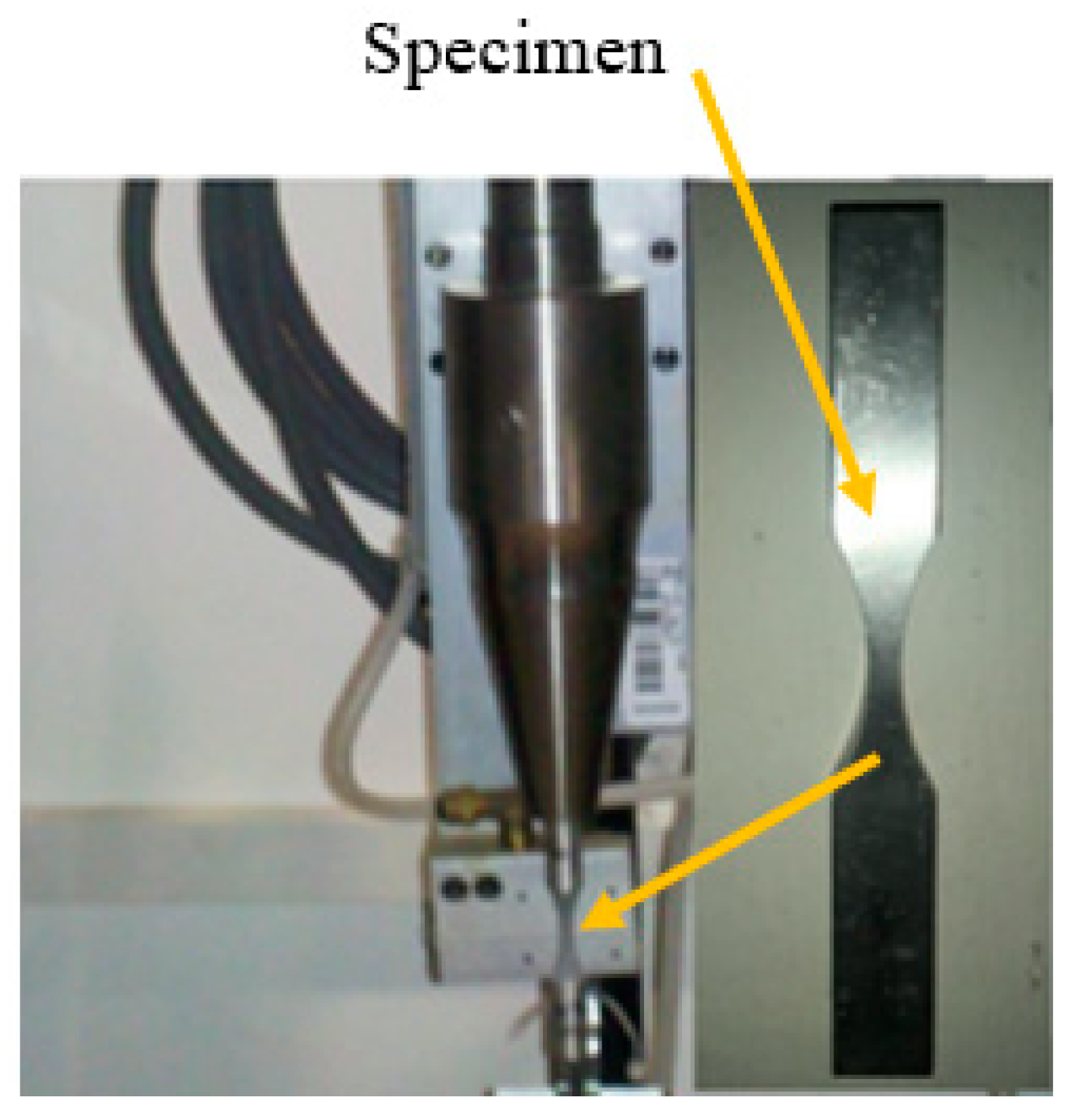
All ultrasonic fatigue tests were performed with the self-designed and constructed machine Figure 3, which is totally controlled by a LabVIEW program (Version 2015, National Instruments, Austin, TX, USA), allowing the test initiation, the record of the number of cycles in real time and the automatic stop with the specimen’s failure. Calibration of displacements of specimens at the free end was carried out by an inductive proximity sensor (Keyence, Itasca, IL, USA), which has a resolution of ±2 μm, working at 1.5 MHz. All tests were obtained at room temperature (close to 23 °C), with environmental humidity between 35% to 55% and full reversed load ratio R = −1.
The experimental start up for each specimen under ultrasonic fatigue tests was as follows: stabilization of the system for 30 s with an applied load of 44 MPa (corresponding to the lower voltage of ultrasonic generator: 10 volts); afterwards, increasing 4.4 MPa each second to attain the desired applied load.
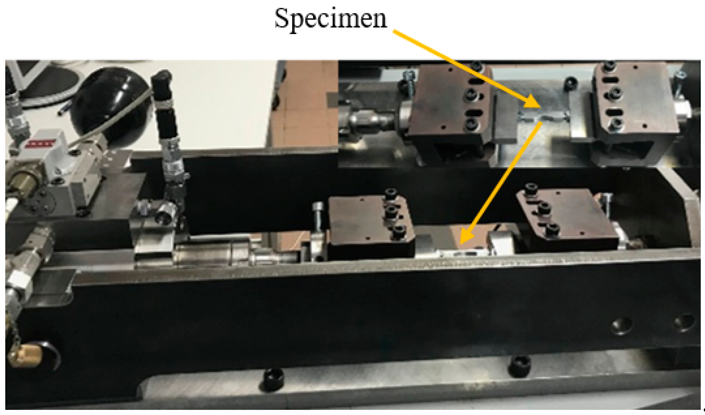
Conventional fatigue tests were conducted on a servo–hydraulic testing machine, in which frequency can be imposed from 0.5 to 20 Hz. The complete system of the machine was developed in the University of Maribor, Slovenia [23]; an overview is depicted in Figure 4. The manufacturing of the parts and the whole controlling system for the machine was configurated to work between 0.5 to 20 Hz; all tests under conventional fatigue were obtained at the highest frequency and with load ratio R = 0.1, at room temperature without control of environmental humidity.
Roughness on surface of testing specimens was measured before and after the conventional fatigue tests, in order investigate the variation of this parameter. The measurements were obtained in longitudinal and transversal direction in regards the principal axis of specimens, using two roughness measuring devices: a TESA Rugosurf 10 G (Renens, Switzerland) and a Mitutoyo SURFTEST SJ-210 (Queréraro, Mexico). The use of these two devices allows to corroborate similarity of the average roughness obtained through the first and second MEASURING device.
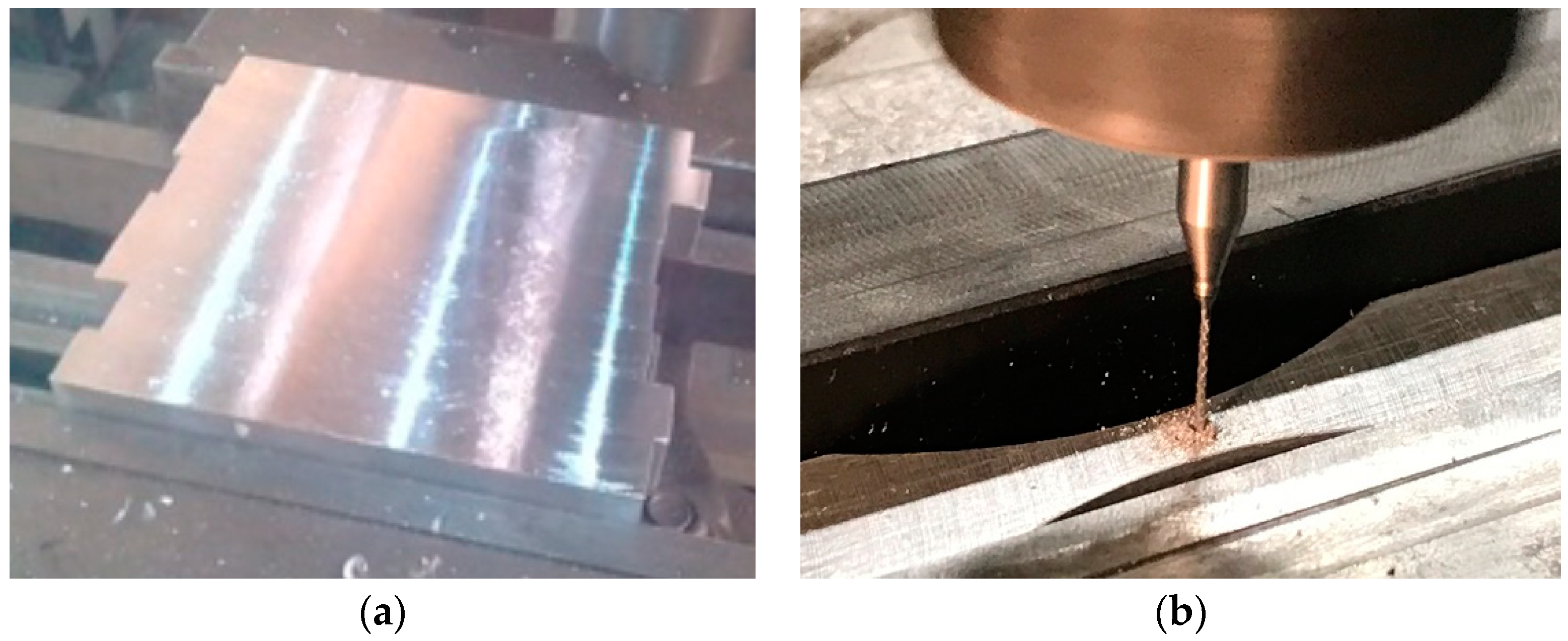
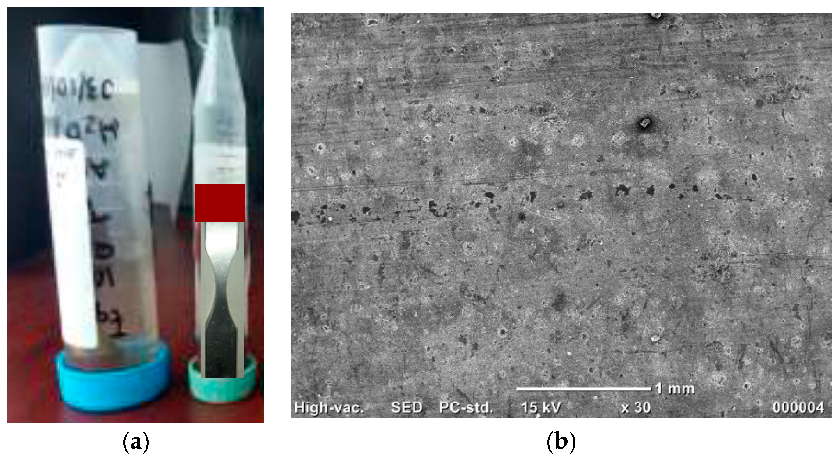
Three initial types of specimens were tested: specimens with nomination A, which are the base material, nomination B with two artificial hemispherical pits (500-μm diameter) in transverse direction in regard the applied load, Figure 5 and nomination C with two artificial hemispherical pits (500-μm diameter), this time longitudinally oriented in regard the applied load, Figure 6. Specimens to be machined at the neck section are presented in Figure 7a (milling machine, model Dyna EM-3116, San José, CA, USA); whereas the two artificial pits were made with a tungsten drill bit of 500-μm-diameter (brand: HANGXIN, model: ZT0.5, Guangzhou, China), as illustrated in Figure 7b. Pre-corrosion was achieved by immersion of specimens during 30 h in a solution of distilled water with 3.5% in weight of NaCl (international standard ESA ECSS-Q-ST-70-37C). Figure 8a presents the process of immersion for pre-corrosion and Figure 8b, the microstructure of pre-corroded specimen on the flat surface, with a higher pit dimension of about 90 μm, approximately.

3. Results

3.1. Fatigue Endurance under Ultrasonic and Conventional Techniques

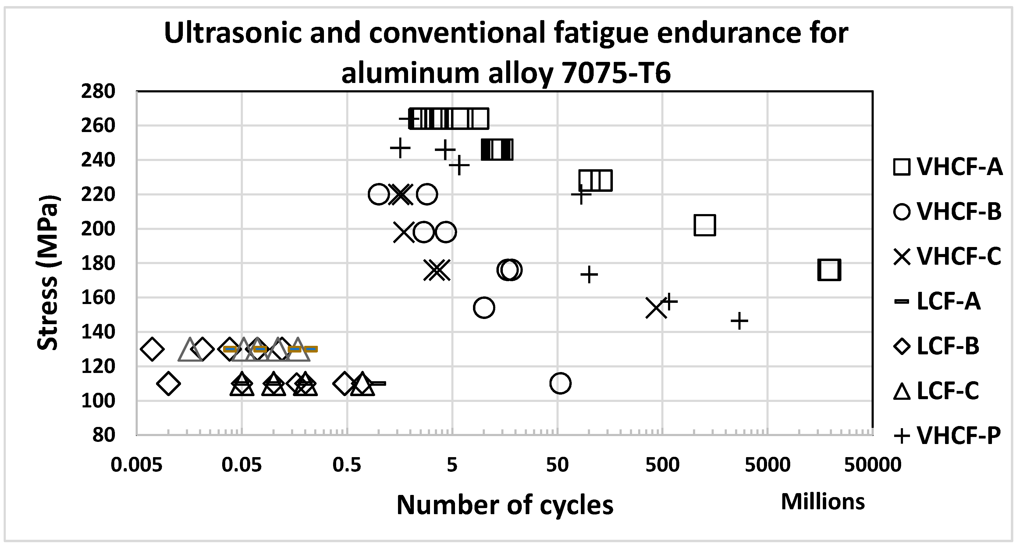
Ultrasonic and conventional fatigue tests on the base material, with two pits and pre-corroded specimens are plotted on Figure 9 (the maximum Von-Mises stresses of fractured specimens).
Nomination for ultrasonic fatigue were as follows: VHCF-A the base material, VHCF-B for specimens with two artificial pitting holes in transverse direction, VHCF-C specimens with two artificial pitting holes in longitudinal direction and VHCF-P for specimens with pre-corrosion. Nomination in conventional fatigue was: LCF-A the base material specimens, LCF-B specimens with two artificial pitting holes in transverse direction and LCF-C specimens with two artificial pitting holes in longitudinal direction.

3.2. Roughness Measurements on the Conventional Fatigue Testing Specimens

Measurements of surface roughness were obtained before and after the conventional fatigue tests, as shown in Table 3.
The roughness parameter Ra was measured in four localizations: (a) longitudinal direction at the flat surface, (b) longitudinal direction at the side of specimen, (c) transverse direction at the flat surface and (d) transverse direction at the side of specimen, as illustrated in Figure 5. The obtained results show that roughness slightly decreases in all the specimens with nomination A (without holes) and in the specimens with nomination B and C (transverse and longitudinal pits, respectively), in the direction of the applying load and slightly increases in the transverse direction. The last behavior may be related to microplastic deformation in tension for the longitudinal direction and compression for the transverse direction.
In Table 3 are listed measured values of roughness before * and after ** the conventional fatigue tests; together with testing parameters: NT the target number of cycles, NF the real number of cycles, Fmax the value of maximum force, σmax the maximum stress in the specimen, R the load ratio and f the frequency of the cyclic loading.

3.3. Microstructure of Crack Initiation and Propagation in Pre-Corroded Specimens and with Two Artificial Pits

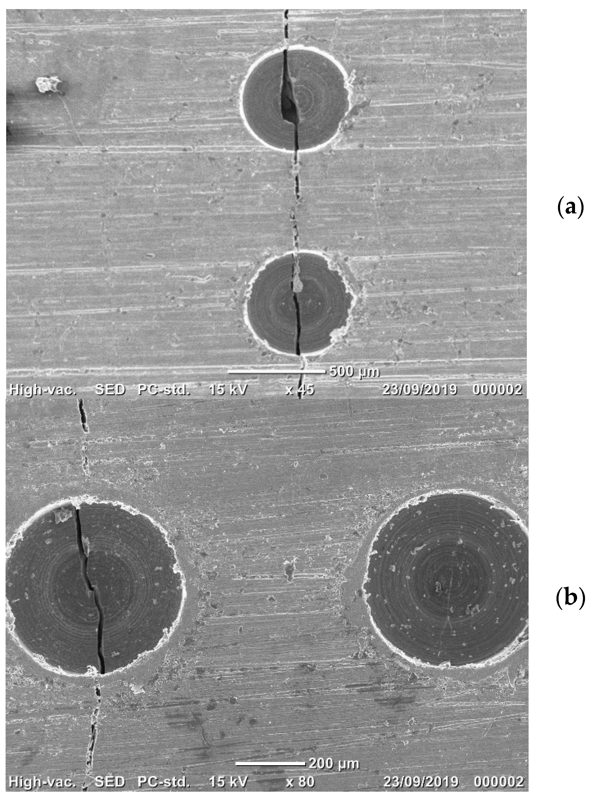
Crack initiation for the pre-corroded specimens was frequently localized in one or some close pre-corrosion pits, as shown in Figure 10a; whereas crack propagation was systematically developed at the neck section of specimens, following an intergranular path, as illustrated in Figure 10b.
For the two artificial pitting holes, the crack initiates at the bottom of pits in the case of transverse pits, Figure 11a and it is localized at the bottom of one pit in the case of longitudinal pits, Figure 11b. A numeric analysis is developed in the next section in order to investigate the stress concentration factors induced by the two artificial pits in the transverse or longitudinal direction and its impact in fatigue endurance.

3.4. Numeric Simulation of Stress Concentration

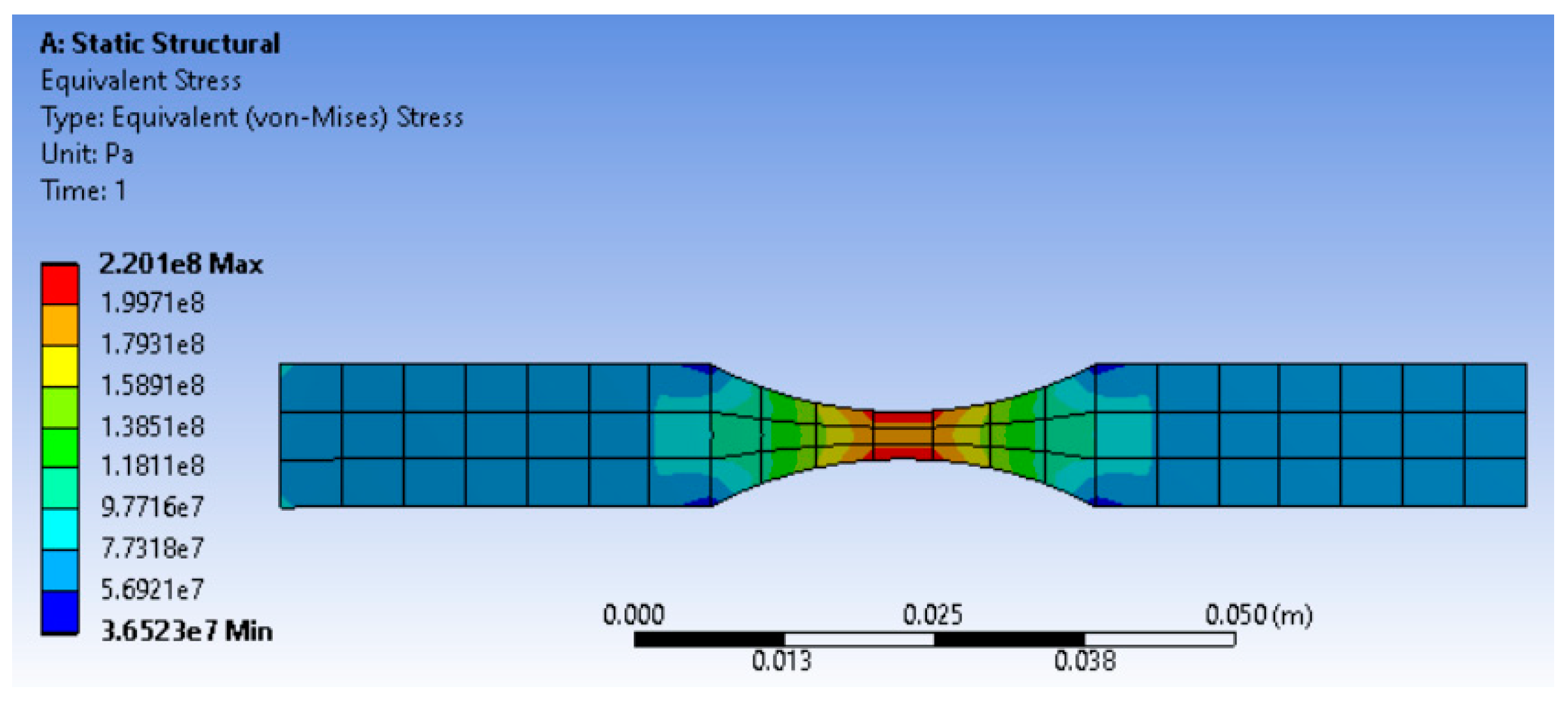
In order to assess the effect of artificial pits (two hemispherical pits oriented in transverse and longitudinal direction in regard the applied load), numeric simulations were carried out on the testing specimen. In Figure 12 is illustrated the stress distribution on the testing specimen without pits, undergoing a total displacement of 130 μm. The maximum Von Mises stress is located at the neck section with the value of 220 MPa (corresponding to the maximum applied stress in Figure 9 for VHCF-B and VHCF-C).
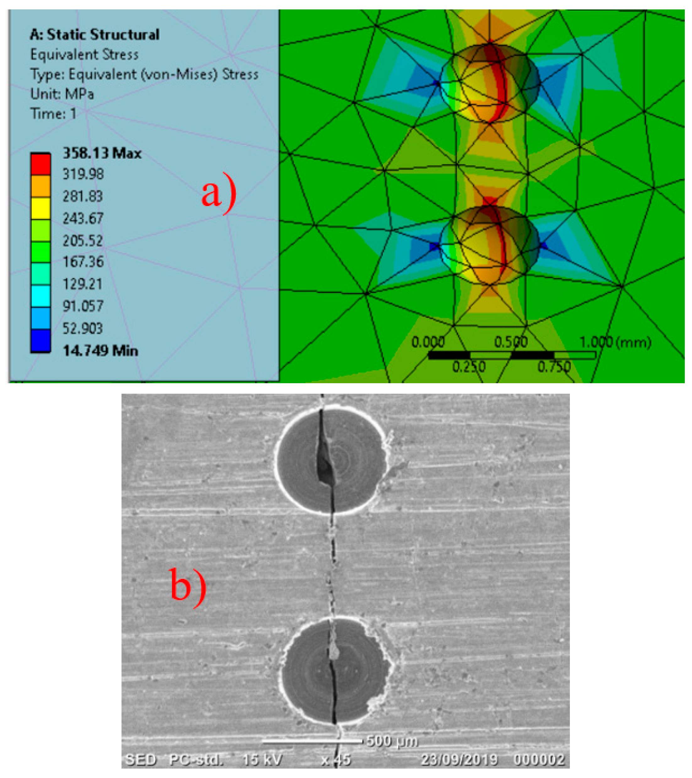
The numeric results for the specimen with two hemispherical pits in transverse direction and separated 500 μm, are presented in Figure 13a. Physical fracture in this type of specimen is shown in Figure 13b; the maximum numeric Von-Mises stress was 358 MPa, approximately.
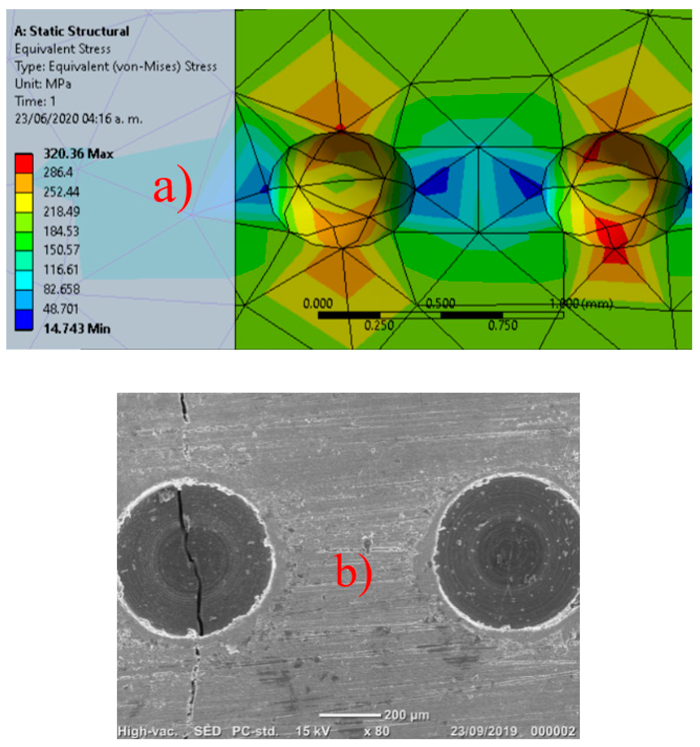
The stress distribution for the specimen with two pits separated 500 μm, this time in longitudinal direction in regard the applied load, is illustrated in Figure 14a. The maximum numeric Von-Mises stress was 320 MPa. Comparing Figure 12, Figure 13 and Figure 14, the stress concentration factor is: 358/220 = 1.63 for two pits in transverse direction and 320/220 = 1.45 for the two pits in longitudinal direction. Stress concentration factors was obtained by numeric simulation in different materials and conditions [24,25,26]. Numeric analysis in Figure 12, Figure 13 and Figure 14 was obtained with the Ansys software (Version R19, Ansys Inc., Canonsburg, PA, USA), SOLID187 element type and 36,039 and 35,945 elements, respectively. One end side of specimen was fixed as boundary condition.

3.5. Numeric Determination of Stress Intensity Factor in Mode I

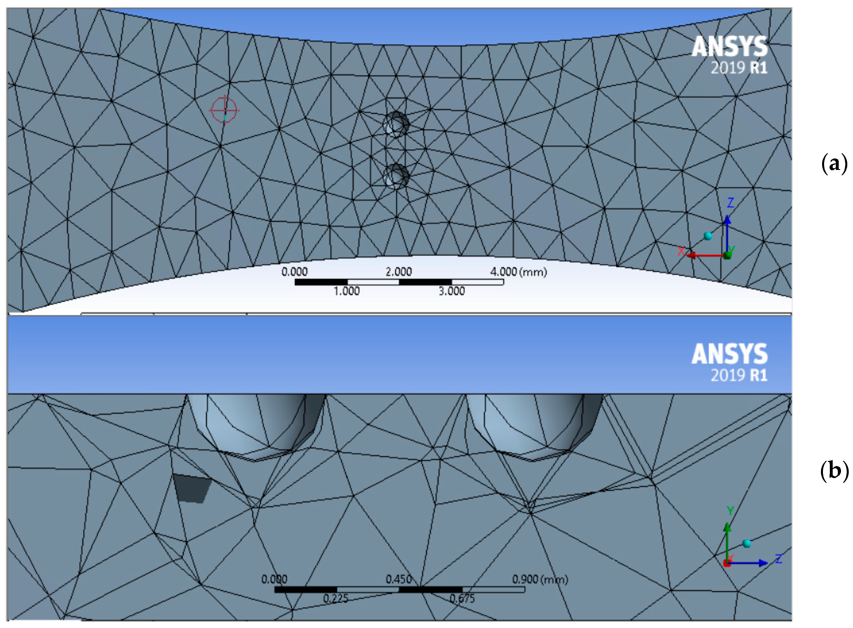
The stress intensity factor (SIF) in mode I during the crack propagation of aluminum alloy 7075-T6 was evaluated assuming as crack initiation a hemispherical pit generated at the surface, Figure 15.
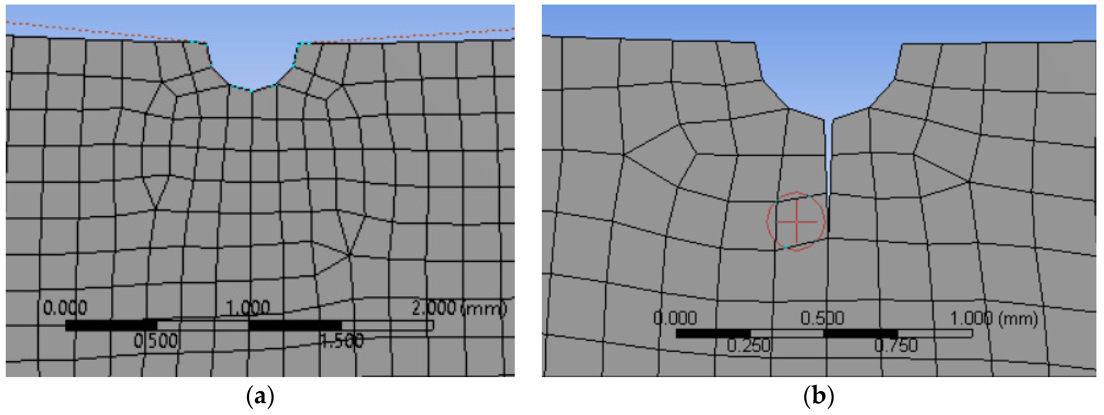
The 3D numeric simulation can be reduced to a 2D numeric simulation under the following considerations: the initial crack length is small (400 μm), compared with the specimen dimensions so that plane stress is assumed. The 2D model is illustrated in Figure 16a, with the initial crack length localized at the bottom of one pit, as shown in Figure 16b. Quadrilateral 2D elements was used: 25,636 elements and 26,190 nodes; fixed one vertical side of specimen for boundary conditions.
Crack growth is determined as straight-line segments across the 2D body in the interval 0–S, divided into steps Δsi, i = 1…n. For a determined state of stress and displacement (σ, u)i, at the step i for the crack geometry Ei, the crack growth evaluation consists to determine the geometry Ei+1, corresponding to i+1 step.
The propagation angle ϕi+1 and the incremental length Δai+1 for each step must be obtained; the selected criteria for the crack growth direction was the normal to the direction of maximum hoop stress [27,28]. Assuming 2D loading and cylindrical coordinate system at the crack tip, the asymptotic circumferential and shear stresses in this region are represented by:
σ φ φ = K I 2 π r   1 4   ( 3 cos ( φ 2 ) + cos ( 3 φ 2 ) ) + K I I 2 π r   1 4   ( 3 sin ( φ 2 ) 3   sin ( 3 φ 2 ) )  
σ r φ = K I 2 π r   1 4   ( sin ( φ 2 ) + sin ( 3 φ 2 ) ) + K I I 2 π r   1 4   ( cos ( φ 2 ) + 3   cos ( 3 φ 2 ) )  
Equation (1) represents the principal stress in the direction of crack propagation. The shear stress σ is assumed vanishing in this direction; then, it is obtained:
σ r φ = 0 = 1 2 π r   cos ( φ 2 ) [ K I 2 ( sin ( φ ) + K I I 2   ( 3 cos φ 1 ) ]
Here: ϕ is the angle of crack propagation in the tip coordinate system.
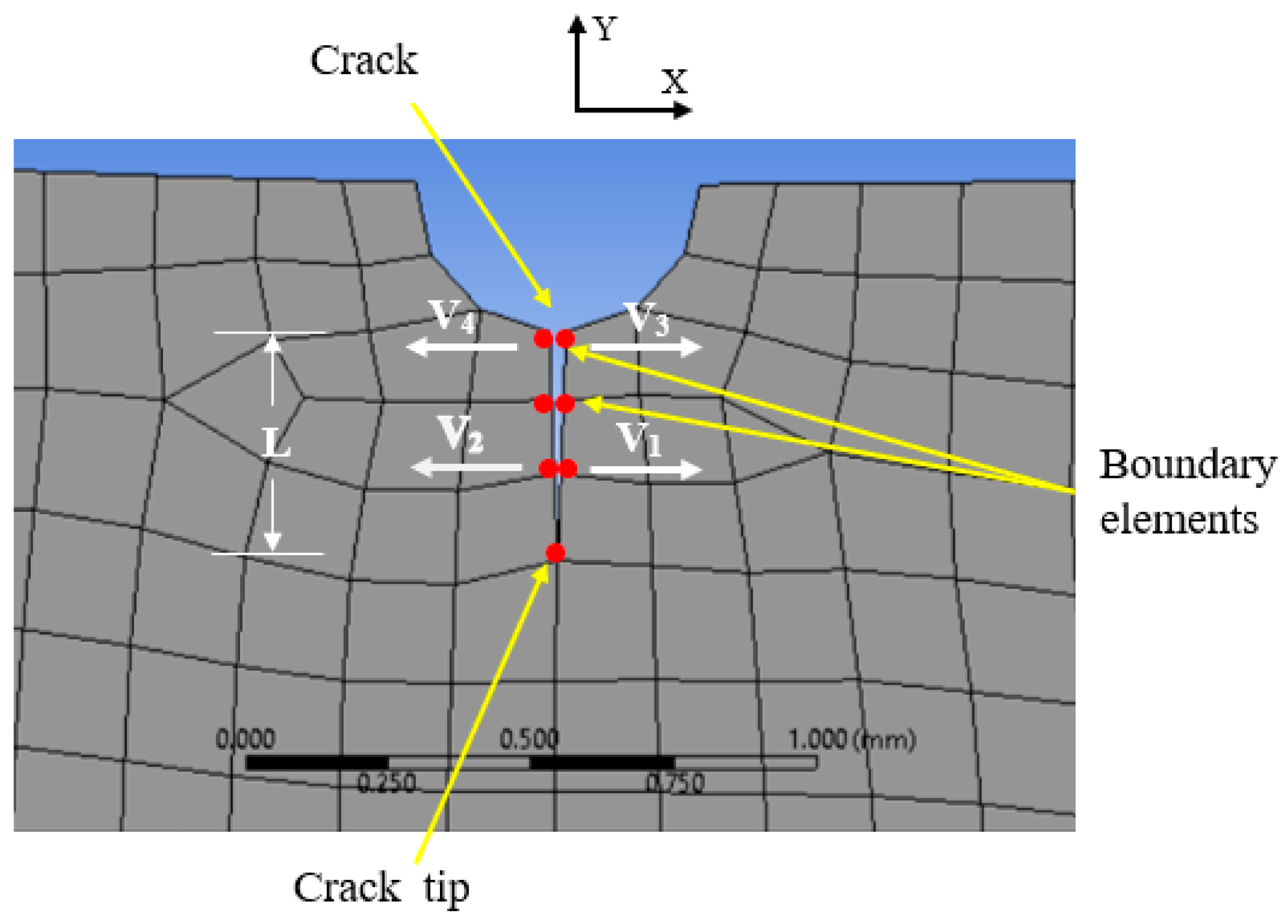
The mixed mode can be approached to single mode loading, which leads to: KII ≈ 0 and equation 3 becomes: KI sin(ϕ) = 0. The last result implies that ϕ = 0 for each step along the crack propagation. Experimental observations seem confirm this result: crack initiation and propagation are developed at the neck section of specimens, perpendicular to the longitudinal axis of specimen, as observed in Figure 11a,b. The numeric domain was constructed with 25,636 quadrilateral elements and 26,190 nodes. KI was evaluated using the displacement correlation method [29,30], with the displacement vectors in the X direction Vi and the equation:
K I = G k + 1 2 π L   [ 4 ( V 1 V 2 ) ( V 3 V 4 ) ]
Figure 17 illustrates the parameters involved for the numeric evaluation of KI. The mechanical properties were shear modulus G = 26 GPa, k = (3–4υ) for plane stress, L is the length of the singular element and υ = 0.33 the Poisson’s coefficient.
The numeric stress intensity factor in mode I was obtained taking the following sequence:
  • Determination of stress and strain distributions on cracked structure;
  • Evaluation of displacements vectors at the crack zone on the X direction, to calculate the stress intensity factor in mode I;
  • Compute the direction (ϕ = 0 for all steps), of crack extension and the incremental crack surface construction;
  • Compute the number of load cycles of last increment for crack growth simulation;
  • Re-meshing of boundary, if necessary;
  • Return to first point.
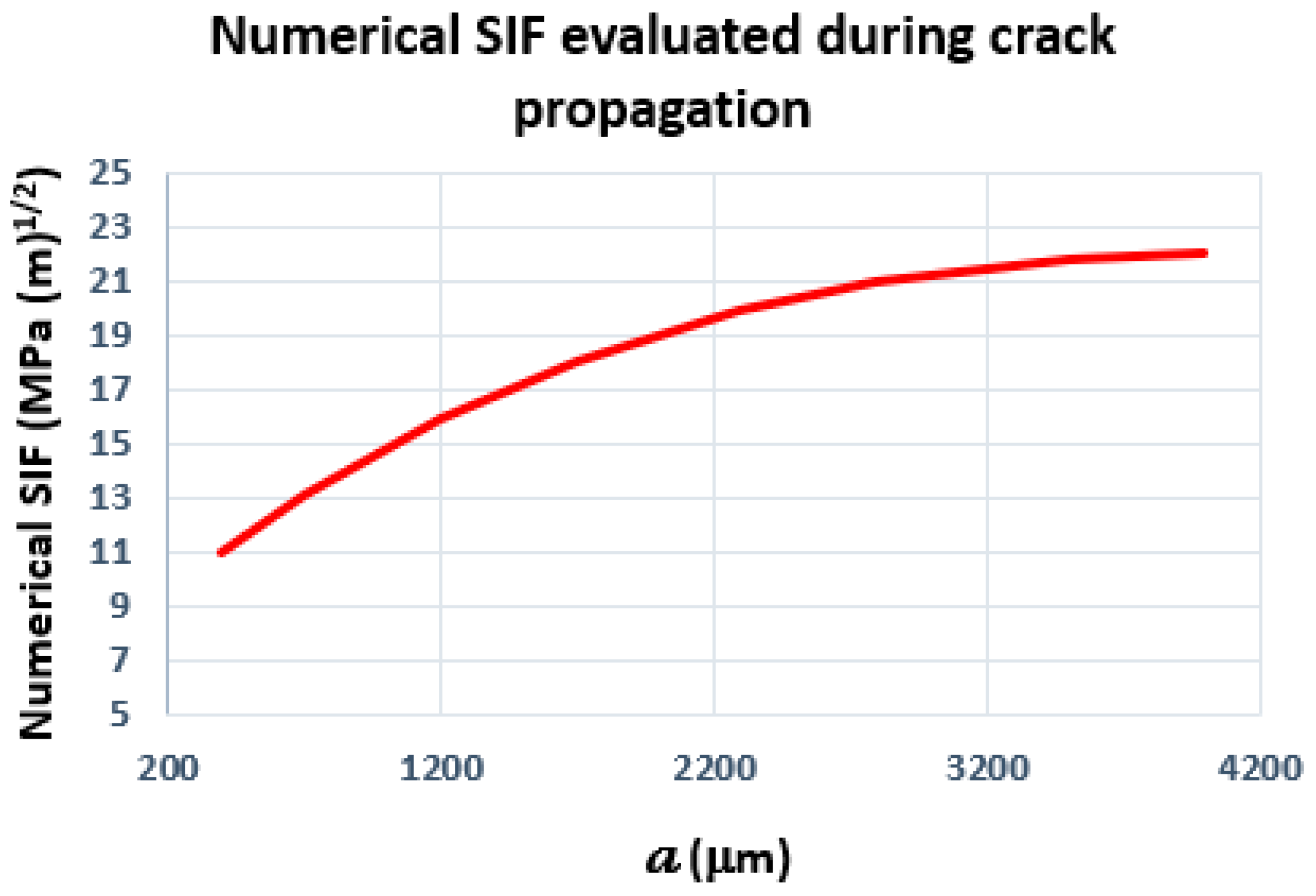
KI was computed from a0 = 400 μm to aend = 4000 μm (the wide at the specimen neck section). Figure 18 shows the evolution of KI determined by FEA, using this method.

3.6. Evaluation of ΔKTH, for Base Material and Specimens with Two Hemispherical Pits in Transverse Direction

The stress intensity factor range threshold ΔKTH was investigated for the base material and specimens with two hemispherical pits in transverse direction regarding its longitudinal axis.
The initial crack size is small compared with the specimen dimension; then, the stress intensity factor in mode I can be obtained with the approximation of edge crack in a semi-infinite body, with the expression:
Δ K I = Y π a   ( Δ σ )
With: Y the geometry correction factor, Y = 1.12. Ultrasonic fatigue tests were carried out with R = −1; the compressive stress does not make contribution toward the advancement of the fatigue crack. Under this condition, the stress intensity factor range was computed from Δσ/2. Ultrasonic fatigue testing in the base material specimens presented no crack propagation using the stress amplitude Δσ/2 = 95 MPa, with an initial crack length a0 = 400 μm; then, Equation (5) leads to: ΔKTH ≈ 3.77 MPa (m)0.5.
The crack growth behavior can be represented in the stable crack propagation zone by the Paris-Gomez-Anderson law:
d a d N = C ( Δ K ) n
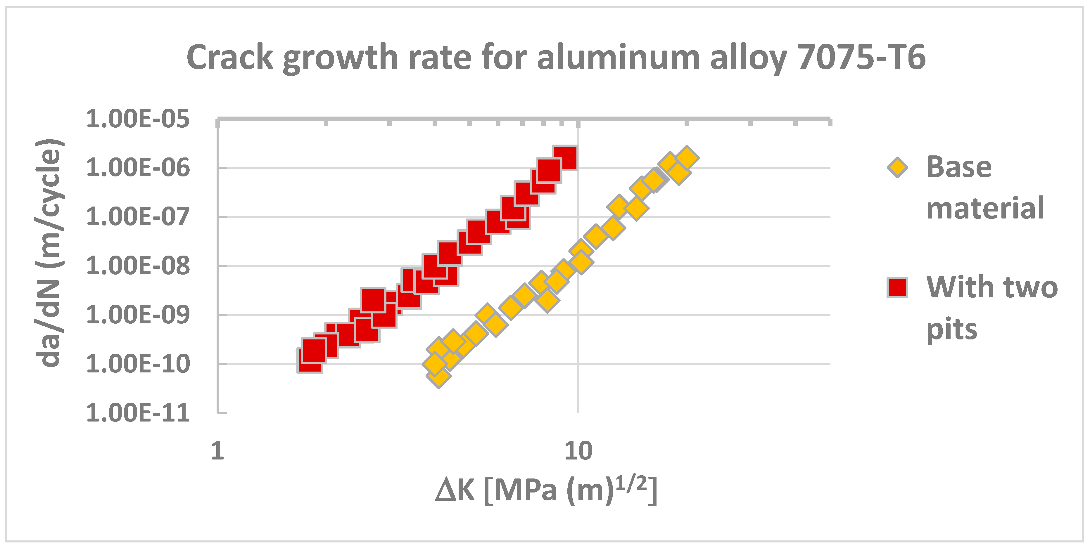
The constant C and n are properties of tested material, determined by experimental results. For the base material of 7075-T6 alloy at room temperature and R = −1, the corresponding values were: C = 0.5 × 10⁻¹² and n = 5 and for specimens with two hemispherical pits in transverse direction, these values were: C = 3.3 × 10⁻¹², n = 5.8. In Figure 19 are plotted the points da/dN-ΔK for the two specimens in the log scale.
Values obtained for ΔKTH were: ≈ 4 MPa (m)0.5 and ≈ 1.8 MPa (m)0.5 for the base material and with two pits, respectively. Reported values for ΔKTH with R = −1 and room temperature yielded close to 4 MPa (m)0.5 [31]. This alloy coated with cladding layer under similar conditions as before and using the effective stress-intensity factor range (ΔKeff), leads to a threshold comprised between 1 and 4 MPa (m)0.5 [32]. The value of ΔKTH for this aluminum alloy was reported decreasing when the load ratio R increases, from R = −1, R = 0 and R = 0.5, regardless of taking ΔK or ΔKeff [33].
On the other hand, the number of cycles in the stable zone of crack growth, may be estimate by the Paris–Gomez–Anderson equation:
N I I = a 0 a e n d d a C ( Δ K ) n = a 0 a e n d d a C [ Y ( a ) Δ σ π a ] n
With: NII the number of cycles in this zone, Y(a) the geometry factor, taken constant along the crack propagation Y(a) = 1.12, a0 and aend the initial and the final crack length, respectively. Assuming that: ΔK = ΔK0 (a/a0)1/2, together with: ΔK0 = Y(a0) Δσ (πa0)1/2, a0 = 400 μm, aend = 4000 μm, Equation (7) becomes:
N I I = 2 a 0 ( n 2 ) C [ Δ K 0 ] n   [ 1 [ a 0 a e n d ] n 2 1 ]
With: ΔK0 ≈ ΔKTH ≈ 3.77 MPa (m)0.5, n = 5 and C = 0.5 × 10⁻¹², the number of cycles of base specimen in this zone is: 678,162 cycles, less than 7% of the total fatigue life (≈10 million of cycles at 245 MPa, Figure 9), For the second case and using the values: C = 3.3 × 10⁻¹² and n = 5.8, the number of cycles in the stable zone of crack growth is reduced to 28,609 cycles, less than 1% of total fatigue life of these specimens (2–3 million of cycles, Figure 9) at 220 MPa [34,35].

4. Discussion

Conventional and ultrasonic fatigue tests were performed on the aluminum alloy 7075-T6 for the base material, specimens with two hemispherical pits disposed in transverse and longitudinal direction in regard the applied load and pre-corroded specimens. Two pits in transverse direction seem induce higher detrimental effect in fatigue endurance associate with the high stress concentration factors, which were determined by numeric simulation. Fatigue endurance for conventional tests revealed similar behavior: the lowest values was observed for specimens with two pits in transverse direction. Ultrasonic fatigue tests on aluminum alloy 7075-T6 were performed under similar condition compared to this study for the nomination VHCF-A [36]. The fatigue endurance was lower compared to the present study for the high load (260 MPa) and similar for the low load (200 MPa); this discrepancy is probably related to difference on the mechanical properties. Concerning measurement of roughness before and after testing under conventional fatigue tests, roughness decreases slightly after fatigue tests in parallel direction to applied load and increases slightly in perpendicular direction to applied load. These results may be associate with tension microplasticity in the first case and compression microplasticity in the second case.
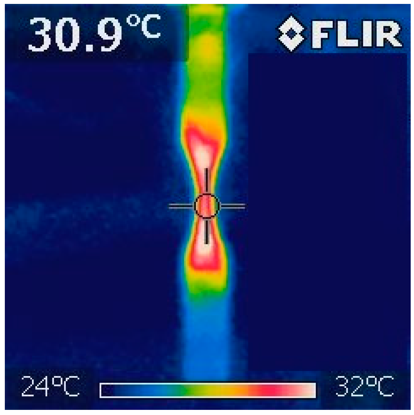
Crack initiates in one or more close pits in the case of pre-corrosion; this localization is at the bottom of one or the two pits, in the case of two artificial pits. Crack initiation is frequently associated with the localization of high stress concentration; physical observations were supported by numeric results. The grain size mean value for this aluminum alloy was 80 μm and crack initiation may be triggered from a single pit occupying a grain or comprising different grains, depending on the crack initiation pit size and localization. The crack propagation in all fatigue tests follows an intergranular path across the specimen neck section; high temperature recorded for conventional fatigue was about 40 °C and close to 31 °C in the case of ultrasonic fatigue, as illustrated in Figure 20, using a thermographic camera.
The stress intensity factor in mode I was evaluated numerically using the Displacement Correlation Method and the simplification of 2D domain; its values range from: ≈11 MPa (m)0.5 at crack initiation (a0 = 400 μm) and ≈22 MPa (m)0.5 at fracture (aend = 4000 μm). The stress intensity factor range threshold ΔKTH was obtained for the base material and specimens with two hemispherical pits in transverse direction: ≈4 and ≈1.8 MPa (m)0.5, respectively; these values are of the order found in literature. The reduction of ΔKTH in the second case is related to stress concentrations induced by the two pits. The number of cycles inside the stable zone of crack growth for the base material and specimens with two pits in transverse direction were evaluated, leading to less than 7% of the total ultrasonic fatigue life for the base material and less than 1% for specimens with two pits in transverse direction.

5. Conclusions

The following conclusions can be drawn from the present investigation;
  • Ultrasonic fatigue tests were obtained on specimens of the aluminum alloy 7075-T6: base material, with two hemispherical pits and pre-corroded. In the case of conventional fatigue: base material and with two hemispherical pits;
  • Pit orientation regarding the applied load plays an important role on the fatigue life of this aluminum alloy: fracture occurs first, for specimen with two transversal pits, following by specimens with longitudinal pits and pre-corroded specimens. The higher fatigue endurance corresponds to specimens of base material;
  • Under conventional fatigue tests Ra roughness parameter slightly decreases in the direction of applied load after tests and slightly increases in perpendicular direction;
  • Cracks initiate frequently associated with one or more pits for pre-corroded specimens and at the bottom of one or the two artificial pits. Crack propagation was always located across the specimen neck section, following a intergranular path;
  • The stress concentration factor Kt, plays a principal role affecting fatigue endurance in the pre-corroded and two pits specimens; values of Kt were obtained by numeric simulation;
  • Stress intensity factor in mode I was obtained by numeric evaluation using the displacement correlation method, from crack initiation to fracture;
  • The stress intensity factor range threshold was obtained for the base material and for specimens with two hemispherical pits in transverse direction;
  • Specimens with pre-corrosion and artificial pits present decrease of the number of fatigue cycles, inside the stable zone of crack growth;
  • Additional physical and numeric investigations should be undertaken to assess the quantitative effects of pits in the corroded surfaces—particularly the interaction effects of close pits associated with the crack initiation and propagation.

Author Contributions

I.F.Z.T.: Conception or design of the work, Data collection, Data analysis and interpretation; M.M.: Conception or design of the work, Data collection, Data analysis and interpretation; G.M.D.A.: Conception or design of the work, Data collection, Data analysis and interpretation, Drafting the article, Critical revision of the article; N.G.: Conception or design of the work, Data collection, Data analysis and interpretation, Drafting the article. All authors have read and agreed to the published version of the manuscript.

Funding

This research was funded by Grant number: CB-241117-2014.

Acknowledgments

The authors express their mention of gratitude to CONACYT (The National Council for Science and Technology, Mexico). An additional mention of gratitude to the University of Michoacán in Mexico and the University of Maribor in Slovenia, for the received support in the development of this work.

Conflicts of Interest

The authors declare no conflict of interests.

References

  1. Wanhill, R.J.H. Aerospace applications of aluminum-lithium alloys. In Aluminum-Lithium Alloys, Processing, Properties and Applications; Prasad, N.E., Gokhale, A.A., Wanhill, R.J.H., Eds.; Butterworth-Heinemann, Elsevier Inc.: Oxford, UK, 2013; pp. 503–535. [Google Scholar]
  2. Zhang, X.; Chen, Y.; Hu, J. Recent advances in the development of aerospace materials. Prog. Aerosp. Sci. 2018, 97, 22–34. [Google Scholar] [CrossRef]
  3. Jawalkar, C.S.; Kant, S.; Kaushik, Y. A Review on use of Aluminium Alloys in Aircraft Components. i-Manager’s J. Mater. Sci. 2015, 3, 33–38. [Google Scholar]
  4. Rambabu, P.; Eswara Prasad, N.; Kutumbarao, V.V.; Wanhill, R.J.H. Aluminium Alloys for Aerospace Applications. In Aerospace Materials and Material Technologies; Indian Institute of Metals Series; Springer: Singapore, 2016; pp. 29–52. [Google Scholar]
  5. Codaro, E.N.; Nakazato, R.Z.; Horovistiz, A.L.; Ribeiro, L.M.F.; Ribeiro, R.B.; Hein, L.D.O. An image analysis study of pit formation on TiÁ 6AlÁ 4V. Mater. Sci. Eng. 2002, 341, 202–210. [Google Scholar] [CrossRef]
  6. DuQuesnay, D.L.; Underhill, P.R.; Britt, H.J. Fatigue crack growth from corrosion damage in 7075-T6511 aluminium alloy under aircraft loading. Int. J. Fatigue 2003, 25, 371–377. [Google Scholar] [CrossRef]
  7. Jones, K.; Hoeppner, D.W. The interaction between pitting corrosion, grain boundaries, and constituent particles during corrosion fatigue of 7075-T6 aluminum alloy. Int. J. Fatigue 2009, 31, 686–692. [Google Scholar] [CrossRef]
  8. Molent, L. Managing airframe fatigue from corrosion pits—A proposal. Eng. Fract. Mech. 2015, 137, 12–25. [Google Scholar] [CrossRef]
  9. Wang, Q.Y.; Kawagoishi, N.; Chen, Q. Effect of pitting corrosion on very high cycle fatigue behavior. Scr. Mater. 2003, 49, 711–716. [Google Scholar] [CrossRef]
  10. Zuñiga Tello, I.F.; Domínguez Almaraz, G.M.; López Garza, V.; Guzmán Tapia, M. Numerical investigation of the stress concentration on 7075-T651 aluminum alloy with one or two hemispherical pits under uniaxial or biaxial loading. Adv. Eng. Softw. 2019, 131, 23–25. [Google Scholar] [CrossRef]
  11. Pao, P.S.; Gill, S.J.; Feng, C.R. On fatigue crack initiation from corrosion pits in 7075-T7351 aluminum alloy. Scr. Mater. 2000, 43, 391–396. [Google Scholar] [CrossRef]
  12. Stanzl-tschegg, S. Fatigue crack growth and thresholds at ultrasonic frequencies. Int. J. Fatigue 2006, 28, 1456–1464. [Google Scholar] [CrossRef]
  13. Domínguez Almaraz, G.M.; Ambriz, J.L.Á.; Cadenas Calderón, E. Fatigue endurance and crack propagation under rotating bending fatigue tests on aluminum alloy AISI 6063-T5 with controlled corrosion attack. Eng. Fract. Mech. 2012, 93, 119–131. [Google Scholar] [CrossRef]
  14. Deng, G.; Nagamoto, K.; Nakano, Y.; Nakanishi, T. Evaluation of the Effect of Surface Roughness on Crack Initiation Life; ICF12; Natural Resources Canada: Ottawa, ON, Canada, 2009; pp. 1–8. [Google Scholar]
  15. Singh, K.; Sadeghi, F.; Correns, M.; Blass, T. A microstructure based approach to model effects of surface roughness on tensile fatigue. Int. J. Fatigue 2019, 129, 105229. [Google Scholar] [CrossRef]
  16. Lai, J.; Huang, H.; Buising, W. Effects of microstructure and surface roughness on the fatigue strength of high-strength steels. Proc. Struct. Integr. 2016, 2, 1213–1220. [Google Scholar] [CrossRef] [Green Version]
  17. Sankaran, K.K.; Perez, R.; Jata, K.V. Effects of pitting corrosion on the fatigue behavior of aluminum alloy 7075-T6: Modeling and experimental studies. Mater. Sci. Eng. A 2001, 297, 223–229. [Google Scholar] [CrossRef]
  18. Shi, P.; Mahadevan, S. Damage tolerance approach for probabilistic pitting corrosion fatigue life prediction. Eng. Fract. Mech. 2001, 68, 1493–1507. [Google Scholar] [CrossRef]
  19. Jakubowski, M. Influence of pitting corrosion on fatigue and corrosion fatigue of ship and offshore structures, Part II—Pit—Crack Interaction. Pol. Marit. Res. 2015, 22, 57–66. [Google Scholar] [CrossRef] [Green Version]
  20. Genel, K. The effect of pitting on the bending fatigue performance of high-strength aluminum alloy. Scr. Mater. 2007, 57, 297–300. [Google Scholar] [CrossRef]
  21. Azar, V.; Hashemi, B.; Rezaeeyazdi, M. The effect of shot peening on fatigue and corrosion behavior of 316L stainless steel in Ringer’s solution. Surf. Coat. Technol. 2010, 204, 3546–3551. [Google Scholar] [CrossRef]
  22. Ribeiro, J.; Monteiro, J.; Lopes, H.; Vaz, M. Moiré Interferometry assessement of residual stress variation in depth on a shot peened surface. Strain 2011, 47, e542–e550. [Google Scholar] [CrossRef]
  23. Tič, V.; Lovrec, D. Development of linear servo hydraulic drive for material testing. In International Conference “New Technologies, Development and Applications”; Lecture Notes in Networks and Systems; Springer: Sarajevo, Bosnia and Herzegovina, 2020; Volume 128, pp. 104–113. [Google Scholar]
  24. Muminovic, A.J.; Saric, I.; Repcic, N. Numerical analysis of stress concentration factors. Proc. Eng. 2015, 100, 707–713. [Google Scholar] [CrossRef] [Green Version]
  25. Yan, W.; Guan, L.; Xu, Y.; Deng, J.-G. Numerical simulation of the double pits stress concentration in a curved casing inner surface. Adv. Mech. Eng. 2017, 9, 1–7. [Google Scholar] [CrossRef] [Green Version]
  26. Pederson, N.L. Stress concentrations in keyways and optimization of keyway des. J. Strain Anal. Eng. Des. 2010, 45, 593–604. [Google Scholar] [CrossRef]
  27. Sukumar, N.; Slorovitz, D.J. Finite element-based model for crack propagation in polycrystalline materials. Comput. Appl. Math. 2004, 23, 363–380. [Google Scholar]
  28. Baydoun, M. Crack propagation criteria in three dimensions using the XFEM and an explicit–implicit crack description. Int. J. Fract. 2012, 178, 51–71. [Google Scholar] [CrossRef]
  29. Fu, P.; Johnson, S.M.; Settgast, R.R.; Carrigan, C.R. Generalized displacement correlation method for estimating stress intensity factors. Eng. Fract. Mech. 2012, 88, 90–107. [Google Scholar] [CrossRef] [Green Version]
  30. Ashoaibi, A.A.; Ariffin, A.K. Evaluation of stress intensity factor using displacement correlation techniques. J. Kejuruter. 2008, 20, 75–81. [Google Scholar] [CrossRef]
  31. Newman, J.C., Jr.; Wu, X.R.; Venneri, S.; Li, C. Small-Crack Effects in High-Strength Aluminum Alloys; NASA RP-1309; Langley Research Center: Hampton, VA, USA, 1994.
  32. Newman, J.C.; Phillips, E.P.; Everett, R.A. Analysis of Fatigue and Fatigue Crack Growth under Constant-and Variable Amplitude Loading; NASA/TM-1999–209329; Langley Research Center: Hampton, VA, USA, 1999.
  33. Newman, J.C., Jr. Fatigue and crack-growth analyses under gigacycle loading on aluminium alloys. Proc. Eng. 2015, 101, 339–346. [Google Scholar] [CrossRef] [Green Version]
  34. Huang, Z.; Wagner, D.; Bathias, C.; Paris, P.C. Subsurface crack initiation and propagation mechanisms in gigacycle fatigue. Acta Mater. 2010, 58, 6046–6054. [Google Scholar] [CrossRef]
  35. Wang, Q.; Kashif-Khan, M.; Bathias, C. Current understanding of ultra-high cycle fatigue. Theor. Appl. Mech. Lett. 2012, 2, 031002. [Google Scholar] [CrossRef] [Green Version]
  36. Wang, Q.T.; Li, T.; Zeng, X.G. Gigacycle fatigue behavior of high strength aluminum alloys. Proc. Eng. 2010, 2, 65–70. [Google Scholar] [CrossRef] [Green Version]
Figure 1. (a) Ultrasonic fatigue specimen dimensions (mm), fitting the resonance condition; (b) dimensions (mm), of the conventional fatigue specimen.
Metals 10 01033 g001aMetals 10 01033 g001b
Figure 2. Natural frequency of vibration in longitudinal direction for aluminum alloy specimen AA7075-T6, obtained by modal analysis.
Metals 10 01033 g002
Figure 3. Ultrasonic testing machine.
Metals 10 01033 g003
Figure 4. Servo-hydraulic machine for conventional fatigue testing.
Metals 10 01033 g004
Figure 5. Specimen B—transverse pits.
Metals 10 01033 g005
Figure 6. Specimen C—longitudinal pits.
Metals 10 01033 g006
Figure 7. (a) Specimens to be machined at the neck section; (b) drilling of the two artificial pits holes.
Metals 10 01033 g007
Figure 8. (a) Pre-corrosion process; (b) pre-corroded surface at the flat side of specimen.
Metals 10 01033 g008
Figure 9. Results of ultrasonic and conventional fatigue tests.
Metals 10 01033 g009
Figure 10. (a) Crack initiation in a pre-corrosion pit; (b) crack propagation following intergranular path.
Metals 10 01033 g010
Figure 11. (a) Crack initiation and propagation for two transverse pits; (b) crack initiation and propagation for two longitudinal pits.
Metals 10 01033 g011
Figure 12. Stress distribution of testing specimen with 130 μm of displacement at the end.
Metals 10 01033 g012
Figure 13. (a) Stress distribution for two pits in transverse direction and 130 μm of total displacement; (b) fracture on two pits in transverse direction.
Metals 10 01033 g013
Figure 14. (a) Stress distribution for two pits in longitudinal direction and 130 μm of total displacement; (b) fracture on two pits in longitudinal direction.
Metals 10 01033 g014
Figure 15. (a) Numeric 3D model for evaluate the stress intensity factor in mode I, (b) section view.
Metals 10 01033 g015
Figure 16. (a) 2D numerical model to evaluate SIF in mode I; (b) initial crack length of 400 μm.
Metals 10 01033 g016
Figure 17. Crack propagation parameters used in numeric simulation.
Metals 10 01033 g017
Figure 18. Numeric stress intensity factor (SIF) evaluation in mode I by the displacement correlation method.
Metals 10 01033 g018
Figure 19. Crack growth rate for the base material and specimens with two pits, under ultrasonic fatigue tests.
Metals 10 01033 g019
Figure 20. Temperature recorded by thermographic camera, during ultrasonic fatigue test.
Metals 10 01033 g020
Table 1. Chemical composition by weight (%) of aluminum alloy 7075-T6.
Zn.MgCuCrFeAl
6.9 Max.2.7 Max.1.87 Max.0.2 Max.0.4 Max.Balance
Table 2. Main mechanical properties of aluminum alloy 7075-T6.
DensityHardnessσyσuPoisson RatioElastic Modulus
(kg/m3)
2800
(HV0.1)
155.12
(MPa)
453
(MPa)
538
(–)
0.33
(GPa)
70
Table 3. Roughness on specimens of aluminum alloy 7075-T6, before * and after ** the conventional fatigue tests.
#NTNFFmax
(KN)
σmax
(MPa)
Rf
(Hz)
Ra Localization
(a)
(μm)
Ra Localization
(b)
(μm)
Ra
Localization
(c)
(μm)
Ra Localization
(d)
(μm)
A1107382,9564.861100.120* 0.1790.2520.2250.705
** 0.1440.3580.2920.230
A250,00050,0004.751100.120* 0.1410.4090.3220.643
A3107460,0024.391100.120* 0.1270.3810.2230.578
** 0.1250.2440.2200.558
A4107354,2153.491100.120* 0.170.3230.1930.871
** 0.1760.2980.2240.548
A51071072.311100.120* 0.1030.5560.1970.747
** 0.090.2830.1820.660
A61051052.251100.120* 0.1050.480.1450.253
** 0.1130.4410.1580.606
A7200,000200,0002.341100.120* 0.1280.3790.1380.590
** 0.1040.2580.1850.575
A81071072.271100.1020* 0.110.6280.1640.619
** 0.1030.3310.1580.590
B1106692,0234.241100.120* 0.310.5380.40.731
** 0.2710.3750.7550.999
B21041044.881100.120* 0.7940.6630.5470.487
B31071072.291100.1020* 0.1660.5180.3860.830
** 0.1130.4230.4670.963
B4107165,0473.381100.120* 0.2280.4670.4030.866
** 0.1450.3930.3420.885
B550,00050,0002.311100.120* 0.1280.4090.250.55
** 0.1030.4470.2190.623
B61051052.291100.1020* 0.1190.5990.180.633
** 0.1250.4500.1890.654
B7200,000200,0002.331100.120* 0.1140.4340.3710.776
** 0.1060.2750.2140.838
C1107335,0334.581100.120* 0.2440.5860.3820.98
** 0.1590.5960.3951.091
C31071072.281100.1020* 0.1630.4830.3360.912
** 0.1490.2880.2780.530
C4700,000700,0002.291100.120* 0.1660.6430.2650.812
** 0.170.4860.2730.909
C550,00050,0002.221100.120* 0.1680.5800.3830.877
** 0.1270.4500.3390.672
C61051052.291100.1020* 0.1550.5380.2790.709
** 0.190.4610.2650.657
C7200,000200,0002.321100.1020* 0.1670.5820.2480.712
** 0.140.2860.2820.715