Article

Effects of Mold Materials on the Interfacial Reaction between Magnesium Alloy and Ceramic Shell Mold during Investment Casting

1
Henan Province Industrial Technology Research Institute of Resources and Materials, Zhengzhou University, Zhengzhou 450001, China
2
Zhengzhou Light Alloy Institute Co., Ltd., Zhengzhou 450041, China
3
No.20 Research Institute of China Electronic Technology Corporation, Xi’an 710068, China
*
Author to whom correspondence should be addressed.
Metals 2020, 10(8), 991; https://doi.org/10.3390/met10080991
Submission received: 21 June 2020 / Revised: 16 July 2020 / Accepted: 21 July 2020 / Published: 23 July 2020

Abstract

:
In order to suppress the interfacial reaction between the ceramic shell mold and the magnesium molten alloy during the investment casting process, a mold material with a high thermodynamic stability based on alkaline zirconium sol (CH4NO3Zr) binder and corundum (Al2O3) powder was prepared. The effects of the mold materials and casting thicknesses on the interfacial reaction were investigated by an optical microscope, X-ray diffraction, a scanning electron microscope, and an energy dispersive spectroscope analysis. The results suggested that the casting poured by the conventional ZrSiO4 mold has a serious reaction on the surface, and the reaction was more severe when the casting thickness was increased. The oxidation layer was approximately 300 μm in some severe areas of 45 mm thickness. The XRD and EDS results showed that the reaction interface mainly contains MgO and Mg2Si. While the casting poured by the Al2O3 mold provides a light and smooth surface, the reaction layer was only 1.5 μm on average. The reaction interface mainly contains MgO and Mg2F.

Graphical Abstract

1. Introduction

Nowadays, the rapid development of material design and functionalization has aroused the widespread concern of scientists [1,2,3]. Investment casting is one of the reasonable solutions for the near net shaping of magnesium alloys. This process has been widely used in the aerospace industry in applications such as engine valves, vanes, turbochargers, and aero-engines due to its superior dimensional accuracy and small surface roughness [4,5]. Investment casting usually requires many factors, such as non-pollution, formability, mold permeability, cost, high thermal shock resistance, and collapsibility [6]. However, it is especially necessary to consider the thermodynamic stability of the shell mold, because magnesium alloy is extremely reactive in the molten state and is prone to oxidation and reacting with mold materials, resulting in serious mold-metal reactions [7]. The reaction would reduce the casting surface accuracy and cause a deterioration of the mechanical properties [7,8]. Therefore, the investment casting process is mainly used to prepare thin-walled magnesium alloy structures at present.
In order to suppress the interfacial reaction between the magnesium alloy and the shell mold, researchers have performed a lot of works, both domestic and international. Some have found that a protective gas of CO2 and 1–2% SF6 can restrict the interfacial reaction effectively [9], but the protection effect become worse when the mold temperature reaches 600 °C [10]. Some works have focused on adding inhibitors (such as NaBF4, KBF4, and FK) into the refractory, but the inhibitors always decompose at the mold firing temperature [10]. Besides this, casting process parameters such as mold preheating and pouring temperatures also have an effect on the interfacial reaction [10,11,12]. Among them, replacing the mold surface coat materials is the most effective and direct method, and the challenge is to find a suitable refractory and binder material.
Refractories are the main component of the shell mold, accounting for more than 90% of the mass. Surface refractory materials have a great influence on the interfacial reaction because they contact with the magnesium molten alloy directly during the solidification process. Researchers have found that some conventional refractories such as calcium sulfate, silicon oxide, and zircon would have a different degree of reaction with the magnesium molten alloy [13,14,15,16,17]. Sin [13,14] evaluated the reactions of a magnesium molten alloy with a plaster mold. The results showed that the casting had a rough surface, and a reaction layer was formed according to the following reaction: 4Mg + SiO2 = 2MgO + Mg2Si. Idris [10] concluded that a zircon-based mold produced inferior ZRE1 investment cast samples. Jafari [18,19] found that a mold based on zircon flour and colloidal silica has a severe reaction with the magnesium alloy. The spot-shaped black residues formed on the casting surface mainly consisted of MgO, Mg2Si, and a small amount of MgAl2O4. Meanwhile, other refractories such as MgO, CaO, and Y2O3 have a high chemical stability with the magnesium alloy. However, MgO and CaO are prone to moisture absorption, making them difficult to promote [20,21,22]. Y2O3 is very expensive, and the prepared slurry is difficult to preserve for a long time. It also has problems after the thermal cycle of the mold [23,24].
Therefore, it is still a problem for scientists and industries to suppress the interfacial reaction between the magnesium alloy and ceramic shell mold using practical, economical, and environmentally friendly methods. The aim of this project is to optimize and develop a refractory and binder system for magnesium alloy investment casting from the practical and economic points of view. An attempt was made to investigate the effects of mold materials on the mold-metal reaction by using optical microscope, X-ray diffraction, scanning electron microscope and energy dispersive spectroscope analyses.

2. Experimental Procedure

2.1. Shell Mold Preparation

In order to evaluate the thermal stability of the mold materials, the melted wax was poured into the stepped mold with different thicknesses (15 mm, 30 mm, and 45 mm) to prepare the wax molds. Figure 1 shows the sketch of the wax patterns. Figure 2 shows the preparation process of the shell mold [25].
In this study, two types of shell molds were prepared. One primary slurry was composed of zircon flour (ZrSiO4, 325 mesh) and colloidal silica binder (SiO2), another slurry was composed of corundum flour (Al2O3, 325 mesh) and alkaline zirconium sol binder (CH4NO3Zr), and they all contained a wetting agent (0.02 wt.%) and an anti-foam agent (0.02 wt.%). Then, the zircon stucco (120 mesh) was applied to form a primary face in the ZrSiO4 mold, while the corundum stucco (120 mesh) was applied in the Al2O3 mold. Further, mullite flour (Al2O3·SiO2, 120 mesh) and silica sol binder (SiO2) were used to prepare the excess slurry of two molds. The excess slurry was coated with 5 layers and sealed with the last layer. Each coat was dried in an environment of 25 °C and a 50% humidity for 8–12 h. The slurry, stucco, and drying time of each coat are shown in Table 1.
After the application of the last coating, the molds were de-waxed in an autoclave for 15 min at 170 °C, with a pressure of about 0.7 MPa. Subsequently, they were heated and fired at 200° C for 60 min and 800 °C for 90 min in a heating furnace.

2.2. Melting and Casting Experiments

The chemical composition of the AZ91D magnesium alloy is given in Table 2, and was analyzed by inductively coupled plasma (ICP). The magnesium alloy ingots were melted and casted under a mixed protective atmosphere of CO2 and SF6 with the ratio of 99:1 in an electric resistance furnace. Argon refining and degassing took place during the smelting. The iron crucible was used for the magnesium alloy melting, argon was used for the refining and degassing during the smelting, and the pouring temperature was 730 °C. Before the pouring process, the mold was preheated at 250 °C for 4 h, and the protective gas was injected into the mold for 60 s.

2.3. Evaluation of Microstructure and Mold-Metal Reaction

Magnesium alloy samples were acquired from the stepped casting at 15, 30, and 45 mm below the surface for analysis and testing. After they were embedded and polished, the microstructures were observed by an Olympus-PMG3 optical microscope (OM, OLYMPUS, Tokyo, Japan) and a Sigma 500 scanning electron microscope (SEM, ZEISS, Jena, Germany) equipped with an energy dispersive spectroscope (EDS, Carl Zeiss AG, Jena, Germany), respectively. The surface phase composition was analyzed by X-ray diffraction (XRD, SHIMADZU, Kyoto, Japan) using Cu Kα radiation performed on a XRD-6100 with a scanning speed of 2°/min and a 2θ diffraction angle range of 30–80°, and a 2014 ICDD standard card was used for the phase comparison. A tensile test was carried out with a DNS−20 universal testing machine (CRIMS, Changchun, China) under a constant speed of 1.0 mm/min at room temperature. Specimens for the tensile test were made into dog-bones with a size of 5 mm in diameter and 25 mm in length using the wire cutting method. Three specimens were tested for each sample. The heat treatment process of the specimens were 375 °C × 2 h + 415 °C × 18 h of the solution treatment and 175 °C × 16 h of the aging treatment.

3. Results and Discussions

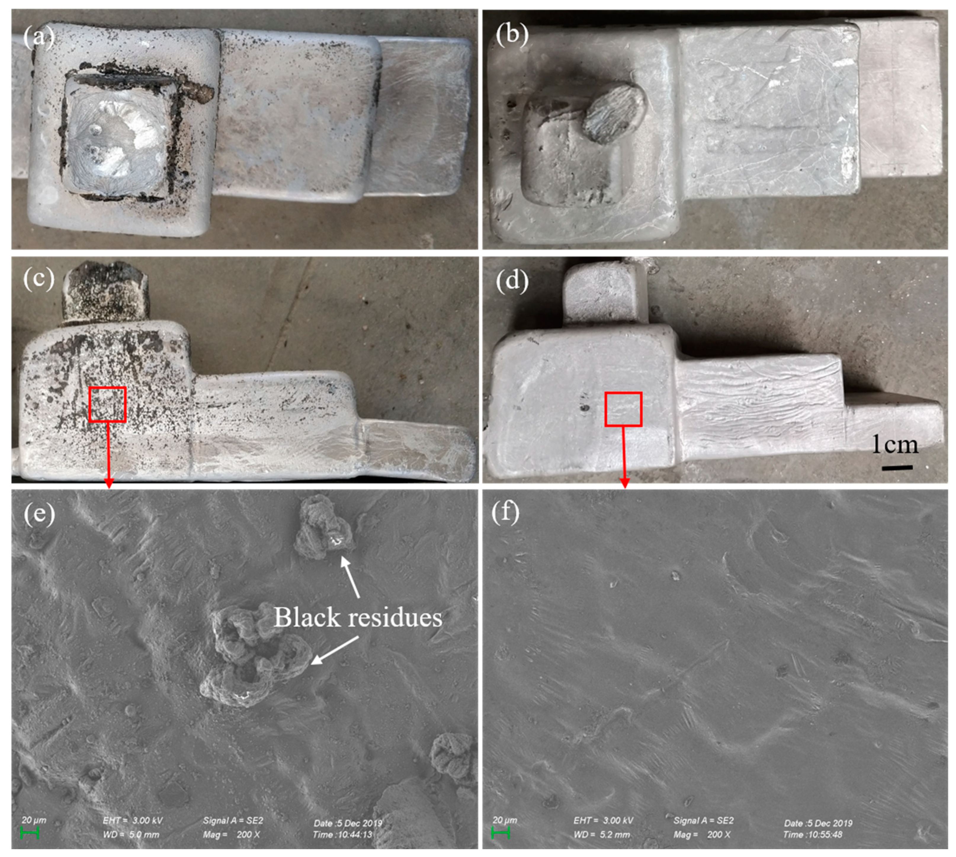
3.1. Surface Structure of the Investment Castings

Figure 3 represents the surface macro-morphology and corresponding SEM micrograph of the AZ91D cast specimens with different mold materials. It can be seen that the casting surface is pretty dark for the ZrSiO4 mold (Figure 3a,c). A significant amount of black residues formed on the surface of 45 mm thickness, a few small granular black residues formed at a 30 mm thickness, and no obvious black residues formed at a 15 mm thickness. Figure 3e shows the SEM micrograph of black residues on the casting surface of 45 mm thickness. The black residues are believed to be the product of the reaction between the molten alloy and the shell mold, or the reaction with the air that came through the mold. The magnesium alloy was casted under atmospheric conditions, so the molten alloy was oxidized inevitably during the casting process. H. Jafari [12,18,19] claimed that the spot-shaped black residues formed on the surface of the AZ91D cast specimens mainly consisted of MgO, Mg2Si, and a small amount of MgAl2O4. Figure 3b,d shows that the casting poured by the Al2O3 mold represents a smooth surface at 15, 30, and 45 mm thicknesses, and there are no obvious black residues. The SEM micrograph of the corresponding area (shown in Figure 3f) shows that the micro-surface is relatively flat at a 45 mm thickness. In addition, it can be clearly seen that the sample thickness has a significant effect on the interfacial reaction from the black residues on the casting surface. As the sample thickness increased, the casting with the ZrSiO4 mold has a denser black residue on the surface, indicating that a more severe interfacial reaction occurred. However, for the casting with the Al2O3 mold, the sample thickness has no obvious effect within 15–45 mm.
Figure 4 shows the XRD analysis of the casting surface with different molds and thicknesses. The results show that the casting surface of ZrSiO4 mold mainly contains Mg, Mg17Al12, MgO, and Mg2Si phase (Figure 4a). The sample thickness has an obvious effect on the diffraction peak of the Mg2Si and MgO phase. As the thickness reduced, the peak of the Mg2Si is lower (Figure 4a), and the peak of the MgO is lower too (Figure 4b). Meanwhile, the casting surface of the Al2O3 mold mainly contains Mg, Mg17Al12, and a small amount of MgO phase (Figure 4c). The peak of MgO is relatively low at different thicknesses. Among the observed phases, Mg and Mg17Al12 are assumed as the matrix and main secondary phase of the AZ91D alloy, MgO is generated by the surface oxidation of the magnesium alloy, and Mg2Si is generated by the interfacial reaction between the magnesium molten alloy and the surface coat materials from the previous research [13]. It can be seen that for the casting with the ZrSiO4 mold, the reaction products increased and the oxidative aggravated when the thickness increased. Meanwhile, the casting with the Al2O3 mold had no obvious effect as the thickness changed.
Figure 5 shows the EDS surface scanning results of the castings poured by different molds at the 45 mm thickness step. It can be seen that all the element contents decrease in the black residue area (Figure 5a). It is speculated that the residues are loose and porous, and the low density of the residues cause the element contents to decrease. In addition, comparing the element density of the casting surfaces with different molds, it can be seen that for the casting of the ZrSiO4 mold, the concentration of the Si and O elements are high and the concentration of the F element is low. The high concentration of Si and O indicates that a interfacial reaction has occurred in this area, and the oxide layer is thicker. The interfacial reaction products might be MgO and Mg2Si according to the XRD results. Meanwhile, the low concentration of the F element indicates that the SF6 gas does not form a dense protective film on the casting surface. Related research [23] found that when the interfacial reaction occurs, magnesium diffuses through the mold and reduces the silica present in the investment material, originating a Mg-Si phase that precipitates in the intermetallic compound with a polyhedral shape. Meanwhile, the surface film of the casting poured by the Al2O3 mold is relatively smooth, with no obvious pits and residues (Figure 5b). The concentration of the Mg and F elements are high, and the concentration of the Si and O elements are low when compared with the ZrSiO4 mold. The lower O element density indicates that the surface oxidation was light and the oxide film was thinner. Meanwhile, the higher F element density indicates that the SF6 protective gas plays well, and a dense protection layer containing the F element was formed on the casting surface.
It can be recognized from the casting surface that the ZrSiO4 mold is more prone to react with the magnesium molten alloy, causing serious oxidation, and the reaction intensity is obviously related to the casting thickness step. An XRD phase analysis shows that the main element that reacts with the magnesium alloy is silicon, which may exist in zirconium powder and the colloidal silica binder included in the ZrSiO4 mold. The results also indicate that the casting thickness has an significant influence on the severity of the interfacial reaction. Generally, thick parts of the casting have a more intense reaction because the cooling rate of the molten alloy becomes slow with the increase in the casting thickness, resulting in a longer contact time between the magnesium molten alloy and the shell mold. Meanwhile, the mold based on corundum powder and alkaline zirconium sol binder has a better chemical stability with the magnesium alloy, leading to a better casting surface quality. Silicon or other reaction compounds are not found on the casting surface of the Al2O3 mold, which indicates that there is no obvious interfacial reaction between the magnesium alloy and the shell mold.

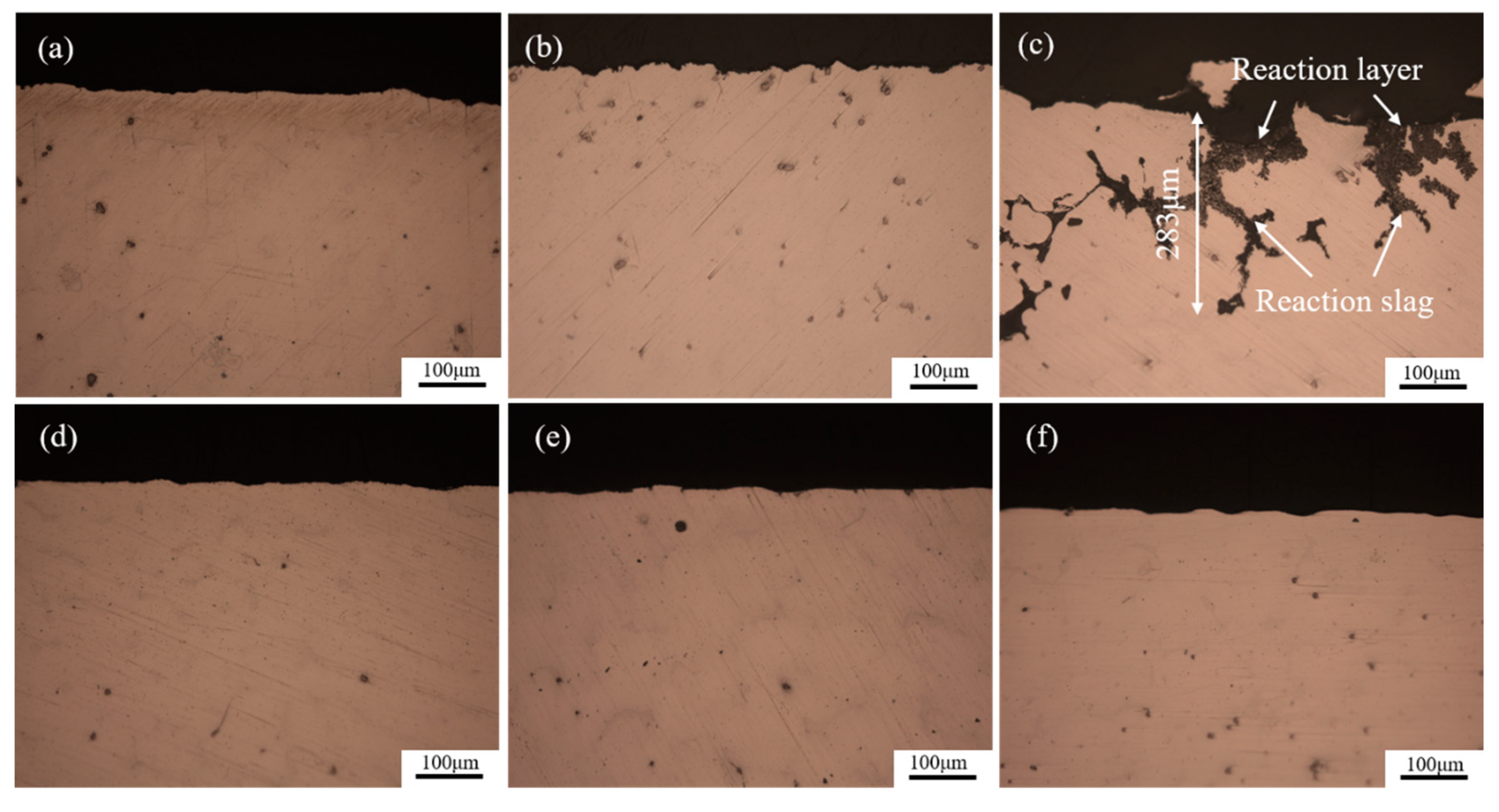
3.2. Section Structure of the Investment Castings

It has been suggested earlier that the relative difference of the mold-metal reaction by section optical microstructure provides a good index for the stability of oxide molds [11,12,13]. Figure 6a–c shows the optical section microstructure of the AZ91D casting with the ZrSiO4 mold. It can be seen that the casting has a smooth surface at a 15 mm thickness (Figure 6a); some pits and bulges at a 30 mm thickness (Figure 6b); and a pretty worse surface at a 45 mm thickness, where the oxidized slag has extended into the cast specimen for approximately 300 μm in some severe areas (Figure 6c). This suggests that the interfacial reaction becomes severe as the sample thickness increases. Figure 7a shows the SEM micrograph of the severe reaction area of Figure 6c. The EDS results suggest that the reaction slag area mainly contains Mg, O, and a little Al (Figure 7b), indicating that the reaction products are magnesium oxide mainly, and a little aluminum oxide. It is known that the severe oxidation at the 45 mm thickness is caused by the slow cooling rate of the magnesium molten alloy. Figure 6e,f shows that the casting with the Al2O3 mold has a smooth interface at different thicknesses, demonstrating that the Al2O3 mold has a better chemical stability to magnesium molten alloy compared with the ZrSiO4 mold. The effect of sample thickness on the interfacial reaction is not obvious.
In order to determine whether a weak reaction occurred at the 30 mm thickness, an SEM micrograph and EDS line analysis are performed on the areas below the surface of 30 mm thickness (Figure 8). In the case of the AZ91D casting into the ZrSiO4 mold (see Figure 8a), the casting surface is rugged and the oxide layer is thick. An EDS line analysis shows that the content of Mg decreases and the content of O and Si increases from the casting inner to the surface. The depth of the oxide layer is about 5 μm from the decrease in Mg. The rise of silicon is considered to be caused by the interfacial reaction between the molten alloy and the shell mold. However, the casting surface is smooth and the oxide layer is thinner in the case of the Al2O3 mold (Figure 8b). An EDS line analysis shows that the content of Mg decreases and the content of F and O increases from the casting inner to the surface. The depth of the oxide layer is about 1.5 μm from the decrease in Mg. The thinner depth of the oxide layer and the increase in the F element illustrate that the casting has a weaker reaction with the Al2O3 mold, and the SF6 protective gas works well. Because the interfacial reaction is always an exothermic reaction, this progress will accelerate the oxidation of magnesium, which will result in more serious oxidized slag. This is the reason why the casting with the ZrSiO4 mold has a thicker oxide layer compared with the Al2O3 mold.
The surface phase analysis and EDS line analysis are synthesized with the casting poured by the ZrSiO4 mold. It is speculated that the reaction area mainly contains Mg, MgO, and Mg2Si. Among them, MgO is brought by the oxidation of the magnesium alloy, while Mg2Si is mainly brought by the interfacial reaction between the surface coat material and the magnesium molten alloy. The interfacial reaction destroyed the formation of the surface protection film, reducing the protective effect of SF6 protective gas and leading a bad flame-retardant effect. Besides this, the interfacial reaction is an exothermic process. The interface temperature will increase sharply as the reaction continues, which further exacerbates the oxidation of the magnesium alloy. Following chemical reactions may exist at the interface of the ZrSiO4 mold and magnesium alloy:
2 Mg ( l ) + O 2 ( g ) = 2 MgO ( s ) , Δ G = 1056.012   kJ   mol
4 Mg ( l ) + SiO 2 ( s ) = Mg 2 Si ( s ) + 2 MgO ( s ) , Δ G = 345.487   kJ   mol
For the casting poured by the Al2O3 mold, the surface layer mainly contains Mg, MgO, and MgF2. There is no obvious interfacial reaction occurred because the surface coat of the Al2O3 mold only contains alumina and zirconia, which have a better chemically stability compared to the magnesium molten alloy. Researchers [26,27,28] have studied the character of the protective surface films formed on the magnesium alloy protected by air/SF6 atmospheres. The results showed that MgO and MgF2 were the only chemical compounds present in the film. The F element on the surface layer speculated that the SF6 protective gas have played a perfect protective effect. The protective gas form a dense oxide film on the surface of the magnesium solution and inhibit the interfacial reaction effectively. The following reactions may exist at the interface of the Al2O3 mold and the magnesium alloy:
2 Mg ( l ) + O 2 ( g ) = 2 MgO ( s ) , Δ G = 1056.012   kJ   mol
2 Mg ( l ) + SF 6 ( g ) + O 2 ( g ) = 2 MgF 2 ( s ) + SO 2 F 2 , Δ G = 1003.634   kJ   mol

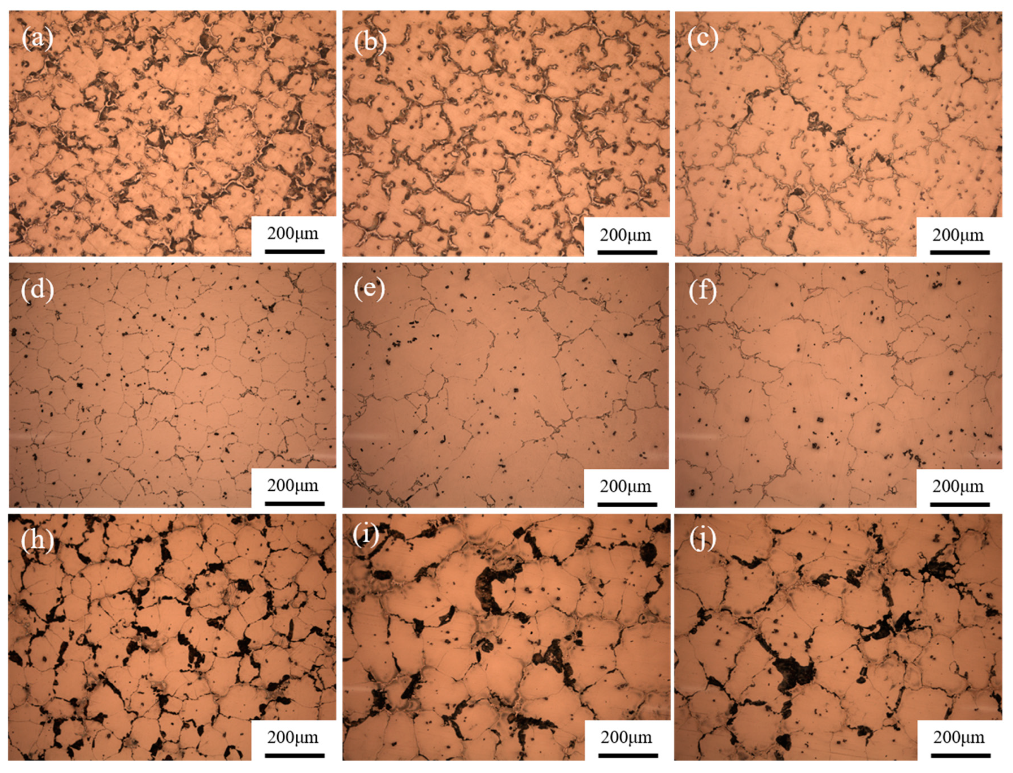
3.3. Microstructure and Mechanical Properties

The AZ91D magnesium investment casting poured by the Al2O3 mold has a better surface quality, so we observed the microstructure and mechanical properties of it. Figure 9 shows the optical microstructure of the sample cut from different thicknesses of AZ91D investment castings in as-cast, solid solution, and aged states; the mold was preheated at 250 °C for 4 h before pouring. The solid solution and aging processes are 375 °C × 2 h + 415 °C × 18 h and 175 °C × 16 h. It can be seen that the section thickness has a significant effect on the grain size and primary phase morphology. The average grains size of the different samples are measured as 154.06 µm at a15 mm thickness, 296.78 µm at a 30 mm thickness, and 340.28 µm at a 45 mm thickness through the linear intercept method. It can be seen that the as-cast samples all contain primary equiaxed α-Mg solid solution, along with β-Mg17Al12 phase and Al-Mn particles (Figure 9a–c), according to the previous studies [21,29]. The primary β-Mg17Al12 phase disappears after the solution treatment (Figure 9d–f) and disperses along the grain boundary after the aging treatment (Figure 9h–j). The differences in the grain size and β-Mg17Al12 phase are closely related to the cooling rate of the magnesium solution at different thicknesses. Generally, the thick part of the casting has a slower cooling rate, resulting in a serious grain growth and second phase growth, while the thin part of the casting was just the reverse [30,31,32,33,34,35]. Besides this, there are some small spots in the solid solution microstructure. They are confirmed as Al-Mn particles by the EDS point analysis results (Figure 10).
Table 3 shows the tensile properties of the AZ91D alloys at different thicknesses after the T6 treatment. The results in the table are the average of three tested samples. It can be seen that the tensile properties are closely related to the casting thicknesses. The casting exhibits the highest mechanical property at a 15 mm thickness; the UTS, YS, and elongation were 235 MPa, 167 MPa, and 5.4%. Meanwhile, the casting at 45 mm thickness has the worst mechanical properties; the UTS, YS, and elongation were 194 MPa, 121 MPa, and 4.0%. It can be seen that the mechanical properties correspond to the casting thickness perfectly. Because the thin part section has a higher solidification rate, this leads to a grain refinement and second phase refinement effect, increasing the tensile properties of the casting [36,37].

4. Conclusions

This study mainly focuses on the effects of mold materials and casting thickness on the interfacial reaction of AZ91D alloy investment casting. The conclusions are as follows:
(1)
Surface layer materials have a significant effect on the interfacial reaction between the AZ91D alloy investment casting and the ceramic shell mold. The chemical stability of the Al2O3 mold is better than that of the ZrSiO4 mold.
(2)
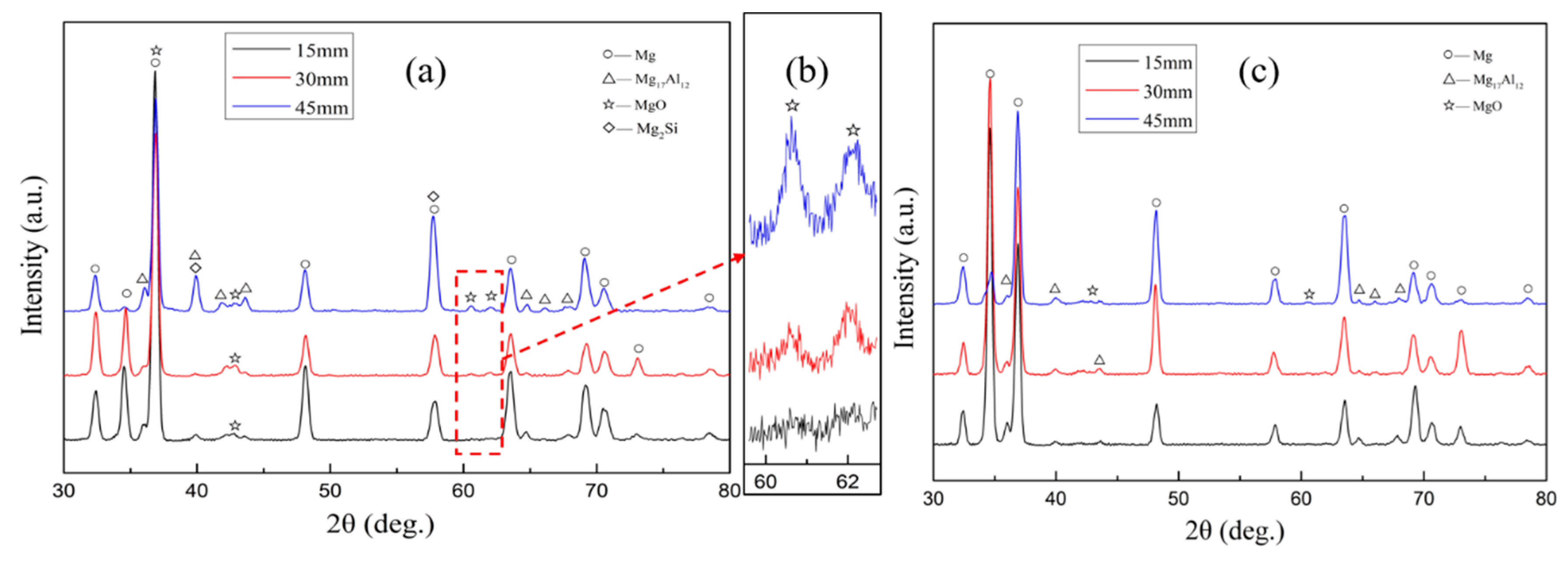
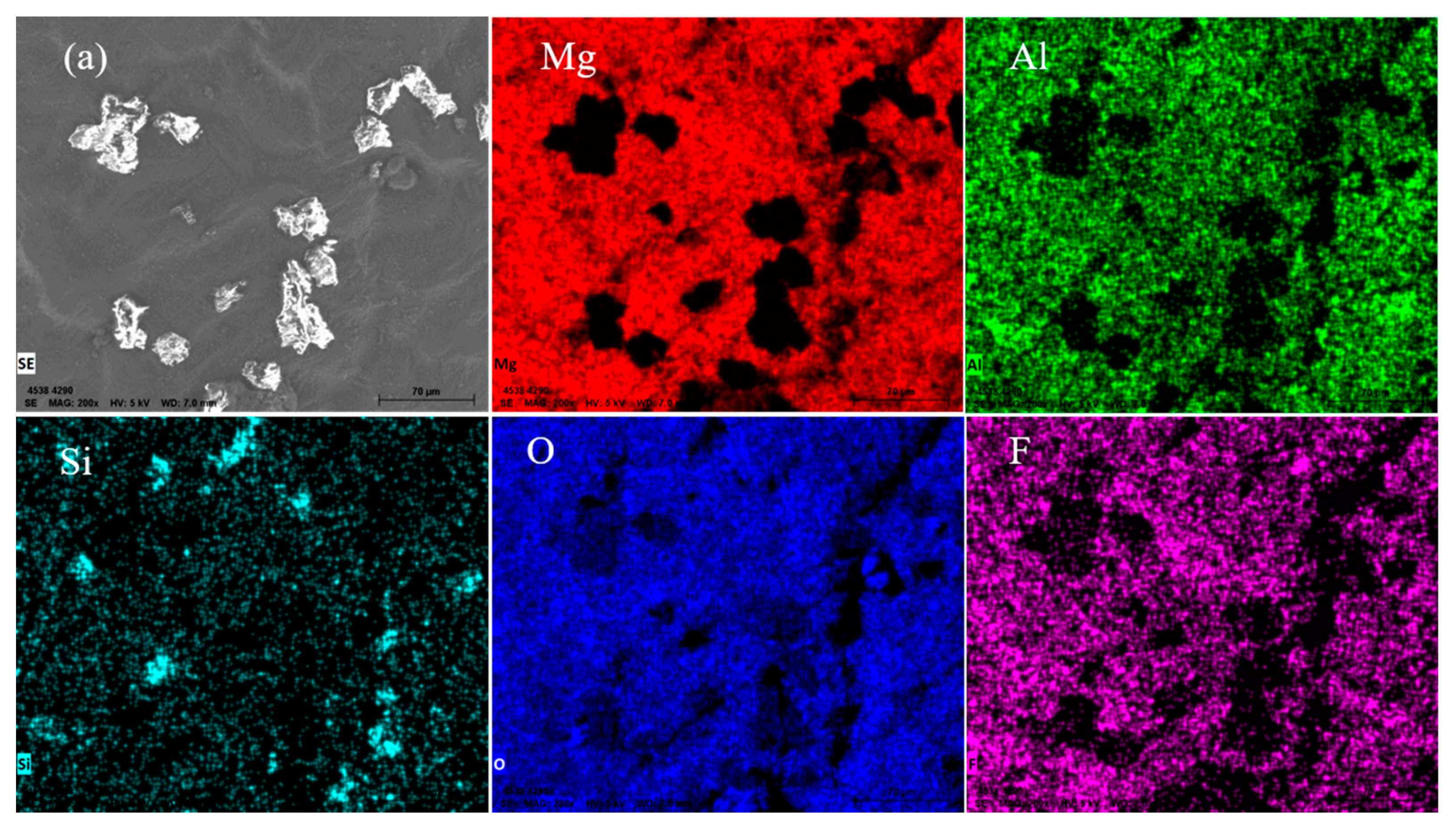
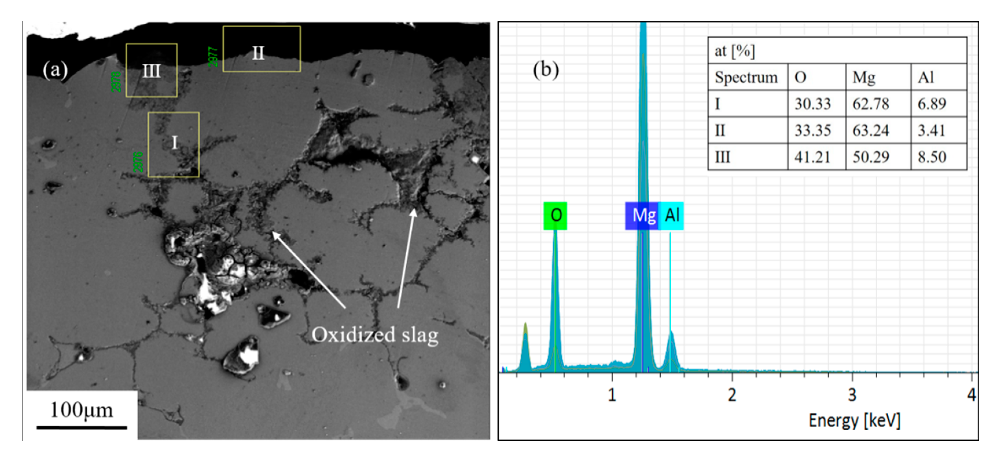
A serious reaction occurred on the casting surface of the ZrSiO4 mold; the main substance reacting with the magnesium alloy is silica. Dense black residues are formed on the casting surface and they mainly contain the reaction products MgO and Mg2Si. The interfacial reaction equation is: 4Mg + SiO2 = Mg2Si + 2MgO.
(3)
Wall thickness has a great influence on the interfacial reaction between the magnesium alloy and the ZrSiO4 mold. The interfacial reaction become more severe as the wall thickness increases. However, for the Al2O3 mold the sample thickness has no obvious effect on the mold-metal interface.
(4)
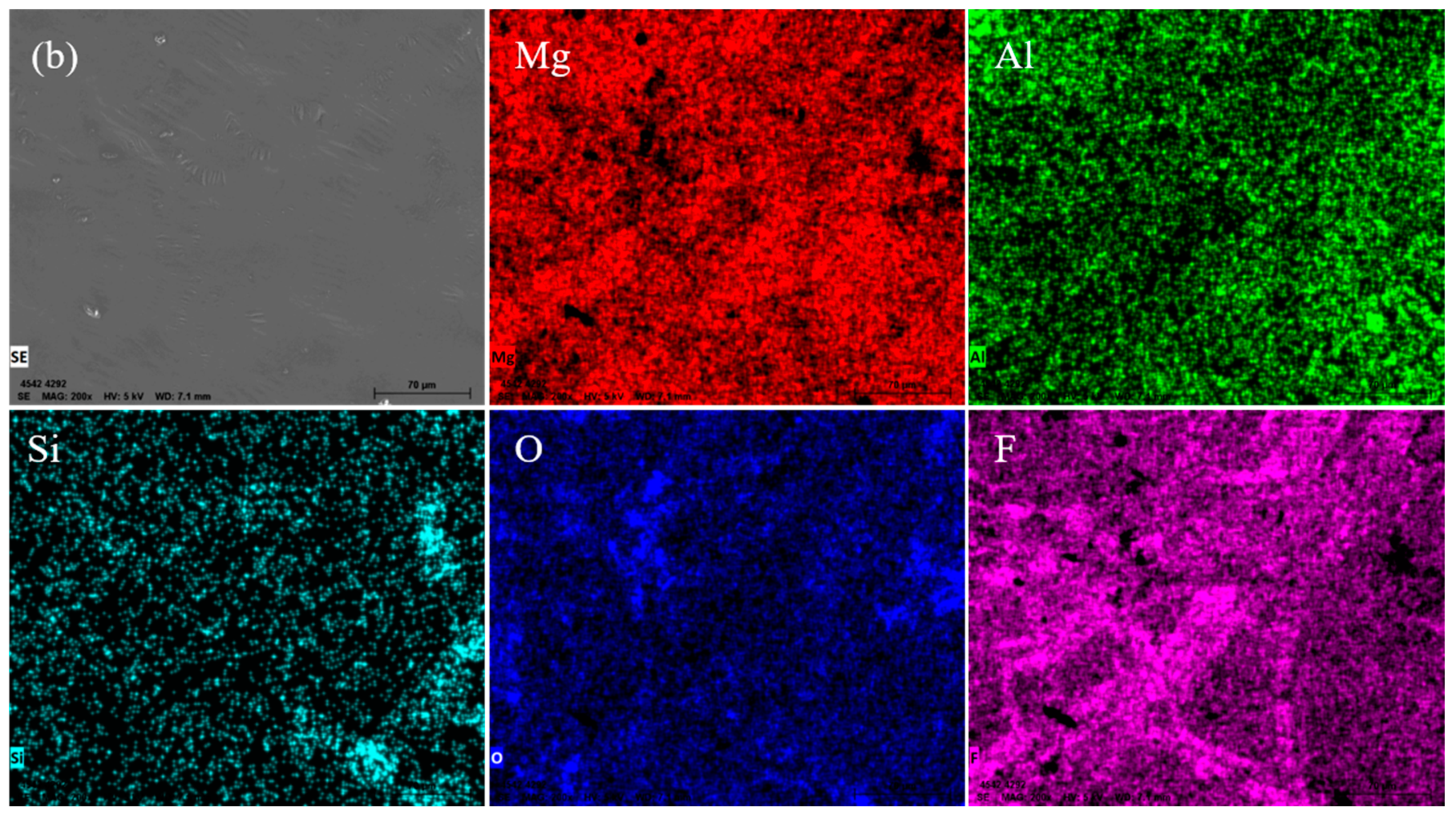
The Al2O3 mold has a good chemical stability to the magnesium molten alloy, leading to a high surface quality investment casting with a smooth and light surface. The main component of the surface film was MgO and Mg2F, and the reaction layer was 1.5 μm thin on average.
(5)
The casting thickness have a great influence on the microstructures and mechanical properties of AZ91D investment casting. The casting at 15 mm thickness has the smallest grain size and highest mechanical properties, with a 235 MPa UTS and 5.4% EL.

Author Contributions

Conceptualization, methodology, writing—original draft preparation, investigation, Y.H.; methodology, writing—review and editing, J.L.; investigation, J.D. and W.Z.; formal analysis, S.Z. and Y.X.; project administration, supervision, funding acquisition, P.Y. All authors have read and agreed to the published version of the manuscript.

Funding

This research was funded by the National Key Research and Development Program of China (No. 2016YFB0301101), China Aluminum Corporation 2018 Youth Science and Technology Talent Star Project of China (2018MXJH10), Key R & D Projects of Shaanxi Province of China (2018ZDXM-GY-144), “Zhengzhou 1125 Jucai Plan” Entrepreneurial Leadership Team Project of China (2015091), Key Scientific Research Project Plan of Colleges and Universities in Henan Province (20A430024) and 13th Five-Year Equipment Pre-research Shared Technology of Equipment Development Department of CMC of China (41422010607).

Conflicts of Interest

The authors declare no conflict of interest.

References

  1. Jia, G.; Du, J. Foreign metal ions to control the morphology of Solution-Liquid-Solid reaction. Cryst. Growth Des. 2018, 18, 7489–7495. [Google Scholar] [CrossRef]
  2. Jia, G.; Du, J. Solution–Liquid–Solid growth of CuInTe2 and CuInSexTe2−x semiconductor nanowires. Inorg. Chem. 2018, 57, 14961–14966. [Google Scholar] [CrossRef]
  3. Jia, G.; Du, J. Catalyst-Assisted Solution–Liquid–Solid synthesis of CdS/CuInSe2 and CuInTe2/CuInSe2 nanorod heterostructures. Inorg. Chem. 2018, 58, 695–702. [Google Scholar] [CrossRef] [PubMed]
  4. Cheah, C.M.; Chua, C.K.; Lee, C.W.; Feng, C.; Totong, K. Rapid prototyping and tooling techniques: A review of applications for rapid investment casting. Int. J. Adv. Manuf. Technol. 2005, 25, 308–320. [Google Scholar] [CrossRef]
  5. Pattnaik, S.; Karunakar, D.B.; Jha, P.K. Developments in investment casting process—A review. J. Mater. Process. Technol. 2012, 212, 2332–2348. [Google Scholar] [CrossRef]
  6. Jiayi, W.; Santosh, R.S.; Paul, C.L.; Guha, M. Design and Topology Optimization of 3D-Printed Wax Patterns for Rapid Investment Casting. Procedia Manuf. 2019, 34, 683–694. [Google Scholar]
  7. Hassan, J.; Mohd, H.I.; Ali, O. A Review of Ceramic Shell Investment Casting of Magnesium Alloys and Mold-Metal Reaction Suppression. Mater. Manuf. Process. 2013, 28, 843–856. [Google Scholar]
  8. Gurutze, A.; Iñaki, H.; Jukka, V.; Cingi, C.; Devenyi, S.; Townsend, J.; Mahmood, S.; Wendt, A.; Weiss, K.; Ben-Dov, A. Development of Investment-Casting Process of Mg-Alloys for Aerospace Applications. Adv. Eng. Mater. 2007, 9, 751–756. [Google Scholar]
  9. Zhan, Z.; Guy, M. Effect of inhibitor gas on mould-magnesium reactions in investment casting. Magnes. Technol. 2004, 197–202. [Google Scholar]
  10. Idris, M.H.; Clegg, A.J. The processing and evaluation of an investment-cast magnesium–base alloy. Trans. Am. Foundrymen’s Soc. 1996, 104, 237–244. [Google Scholar]
  11. Sin, S.L.; Dubé, D. Influence of process parameters on fluidity of investment-cast AZ91D magnesium alloy. Mater. Sci. Eng. A 2004, 386, 34–42. [Google Scholar] [CrossRef]
  12. Hassan, J.; Mohd, H.I.; Ali, O.; Farahany, S. In situ melting and solidification assessment of AZ91D granules by computer-aided thermal analysis during investment casting process. Mater. Des. 2013, 50, 181–190. [Google Scholar]
  13. Sin, S.L.; Dubé, D.; Tremblay, R. Interfacial reactions between AZ91D magnesium alloy and plaster mould material during investment casting. Mater. Sci. Technol. 2006, 22, 1456–1463. [Google Scholar] [CrossRef]
  14. Sin, S.L.; Dubé, D.; Tremblay, R. An investigation on microstructural and mechanical properties of solid mould investment casting of AZ91D magnesium alloy. Mater. Charact. 2008, 59, 178–187. [Google Scholar] [CrossRef]
  15. Shaekwang, K.; Taewhan, H.; Youngjig, K. Evaluation of Thermal Stability of Mold Materials for Magnesium Investment Casting. Mater. Trans. 2001, 42, 539–542. [Google Scholar]
  16. Kim, S.K.; Youn, J.I.; Kim, Y.J. Rotating cylinder manufacturing method and investment casting of SiCp/AZ91 HP magnesium composites. Mater. Sci. Technol. 2000, 16, 769–775. [Google Scholar] [CrossRef]
  17. Shaekwang, K.; Myounggyun, K.; Taewhan, H. Investment Casting of AZ91HP Magnesium Alloy. Met. Mater. 2000, 6, 275–279. [Google Scholar]
  18. Jafari, H.; Idris, M.H.; Ourdjini, A.; Kadir, M.R.A. An investigation on interfacial reaction between in-situ melted AZ91D magnesium alloy and ceramic shell mold during investment casting process. Mater. Chem. Phys. 2013, 138, 672–681. [Google Scholar] [CrossRef]
  19. Hassan, J.; Mohd, H.I.; Ali, O. An alternative approach in ceramic shell investment casting of AZ91D magnesium alloy: In situ melting technique. J. Mater. Process. Technol. 2014, 214, 988–997. [Google Scholar]
  20. Cingi, C. Mold-Metal Reactions in Magnesium Investment Castings; ProQuest Dissertations Publishing: Ann Arbor, MI, USA, 2006; pp. 37–42. [Google Scholar]
  21. Freitag, L.; Schafföner, S.; Lippert, N.; Fabauer, C.; Aneziris, C.G.; Legner, C.; Klotz, U.E. Silica-free investment casting molds based on calcium zirconate. Ceramics International. Ceram. Int. 2017, 43, 6807–6814. [Google Scholar] [CrossRef]
  22. Vyas, A.V.; Ayar, V.S.; Sutaria, M.P. Investigation on reactive wetting during investment casting of magnesium alloy AZ91. Mater. Today Proc. 2020, 2, 1–6. [Google Scholar] [CrossRef]
  23. Lopes, V.; Puga, H.; Barbosa, J.; Teixeira, J.C. Effect of yttria mould coating on the investment casting of AZ91D-1wt % CaO magnesium alloy. Int. J. Met. 2019, 14, 98–107. [Google Scholar]
  24. Gomes, F.; Puga, H.; Barbosa, J.; Ribeiro, C.S. Effect of melting pressure and superheating on chemical composition and contamination of yttria-coated ceramic crucible induction melted titanium alloys. J. Mater. Sci. 2011, 46, 4922–4936. [Google Scholar] [CrossRef] [Green Version]
  25. Chen, B.; Jiang, B.; Xu, Y. Investment Casting Manual; Machinery Industry Press: Beijing, China, 2000; pp. 3–5. [Google Scholar]
  26. Dong, H.; Jin, Z.; Jinfeng, H.; Yong, L.; Guangyu, H. A review on ignition mechanisms and characteristics of magnesium alloys. J. Magnes. Alloy. 2020, 8, 329–344. [Google Scholar]
  27. Cashion, S.P.; Ricketts, N.J.; Hayes, P.C. Characterisation of protective surface films formed on molten magnesium protected by air/SF6 atmospheres. J. Light Met. 2002, 2, 37–42. [Google Scholar] [CrossRef]
  28. Pettersen, G.; Øvrelid, E.; Tranell, G.; Fenstad, J.; Gjestland, H. Characterisation of the surface films formed on molten magnesium in different protective atmospheres. Mater. Sci. Eng. A 2002, 332, 285–294. [Google Scholar] [CrossRef]
  29. Zeng, R.; Chiu, Y.; Jones, I.P. Characterisation of nano-sized Al–Mn–(Mg) particles in AZ91 and their effect on Mg17Al12 precipitation. J. Alloy. Compd. 2013, 579, 34–38. [Google Scholar] [CrossRef]
  30. Easton, M.; Abbott, T.; Cáceres, C. The effect of microstructural features and defects on the ductility of high-pressure die cast AS21, AM60 and AZ91. Mater. Sci. Forum 2003, 147, 419–422. [Google Scholar] [CrossRef]
  31. Nawrocki, J.; Motyka, M.; Szeliga, D.; Ziaja, W.; Cygan, R.; Sieniawski, J. Effect of cooling rate on macro-and microstructure of thin-walled nickel superalloy precision castings. J. Manuf. Process. 2020, 49, 153–161. [Google Scholar] [CrossRef]
  32. Jia, G.; Wang, C.; Yang, P.; Liu, J.; Zhang, W.; Li, R.; Zhang, S.; Du, J. Sulfur-free synthesis of size tunable rickardite (Cu3−xTe2) spheroids and planar squares. R. Soc. Open Sci. 2019, 6, 181602. [Google Scholar] [CrossRef] [Green Version]
  33. Jia, G.; Liu, B.; Wang, K.; Wang, C.; Yang, P.; Liu, J.; Zhang, W.; Li, R.; Zhang, S.; Du, J. CuInTe2 Nanocrystals: Shape and Size Control, Formation Mechanism and Application, and Use as Photovoltaics. Nanomaterials 2019, 9, 409. [Google Scholar] [CrossRef] [PubMed] [Green Version]
  34. Wang, K.; Liu, B.; Yang, P.; Liu, J.; Zhang, W.; Wang, C.; Lv, H.; Jia, G.; Li, R.; Zhang, S. One-pot synthesis of branched CuInSe2 nanowires based on solution-liquid-solid method and their implementation in photovoltaic devices. J. Cryst. Growth 2019, 523, 125152. [Google Scholar] [CrossRef]
  35. Jia, G.; Wang, K.; Liu, B.; Yang, P.; Liu, J.; Zhang, W.; Li, R.; Wang, C.; Zhanag, S.; Du, J. Cation exchange synthesis of CuInxGa1−xSe2 nanowires and their implementation in photovoltaic devices. RSC Adv. 2019, 9, 35780. [Google Scholar] [CrossRef] [Green Version]
  36. Zheng, N.C.; Li, X.F.; Yan, S.; Wang, Q.; Qiao, R.; Hu, J.H.; Fan, J.J.; Cao, G.Q.; Shao, G.S. Nano-porous hollow Li0.5La0.5TiO3 spheres and electronic structure modulation for ultra-fast H2S detection. J. Mater. Chem. A 2020, 8, 2376–2386. [Google Scholar] [CrossRef]
  37. Flemings, M.C. Solidification Processing; Metallurgical Transactions: New York, NY, USA, 1974. [Google Scholar]
Figure 1. Sketch of the wax patterns (unit: mm).
Metals 10 00991 g001
Figure 2. Preparation process of the shell mold [25].
Metals 10 00991 g002
Figure 3. Macro-morphology and SEM micrograph of the AZ91D castings with different molds: (a,c,e) ZrSiO4 mold; (b,d,f) Al2O3 mold.
Metals 10 00991 g003
Figure 4. XRD analysis of the casting surface with different molds and thicknesses: (a,b) ZrSiO4 mold; (c) Al2O3 mold.
Metals 10 00991 g004
Figure 5. EDS surface scanning results of the castings poured by different molds at the 45 mm thickness step: (a) ZrSiO4 mold; (b) Al2O3 mold.
Metals 10 00991 g005aMetals 10 00991 g005b
Figure 6. Optical section microstructure of the areas below the surface of the castings with different molds and different thicknesses: (ac) ZrSiO4 mold; (df) Al2O3 mold; (a,d) 15 mm; (b,e) 30 mm; (c,f) 45 mm.
Metals 10 00991 g006
Figure 7. SEM image of the areas below the surface of the casting with the ZrSiO4 mold at a 45 mm thickness: (a) SEM micrograph; (b) EDS analysis results of the corresponding area.
Metals 10 00991 g007
Figure 8. SEM micrograph and EDS line scanning of the areas below the surface of the castings with different molds at a 30 mm thickness: (a) ZrSiO4 mold; (b) Al2O3 mold.
Metals 10 00991 g008
Figure 9. Optical microstructure of the AZ91D investment casting at different thicknesses and states: (a,d,h) 15 mm; (b,e,i) 30 mm; (c,f,j) 45 mm; (ac) at-cast; (df) homogenized; (hj) aged.
Metals 10 00991 g009
Figure 10. SEM and EDS point analysis results of the spots in the solid solution microstructure.
Metals 10 00991 g010
Table 1. The slurry, stucco, and drying time of each coat for different molds.
Mold TypeCoat No.SlurryStuccoDry Time (h)
OxideBinder
ZrSiO4 mold1zircon
(325 mesh)
Colloidal silicazircon powder
(120 mesh)
12
2–6mullite
(120 mesh)
Colloidal silicamullite
(40–80 mesh)
8
7mullite
(120 mesh)
Colloidal silica 8
Al2O3 mold1corundum
(325 mesh)
alkaline zirconium solcorundum powder
(120 mesh)
12
2–6mullite
(120 mesh)
Colloidal silicamullite
(40–80 mesh)
8
7mullite
(120 mesh)
Colloidal silica 8
Table 2. Chemical composition of the investment casting of the AZ91D magnesium alloy (wt.%).
AlZnMnFeSiCuNiMg
8.950.540.33<0.001<0.01<0.001<0.001Bal.
Table 3. Tensile properties of the AZ91D alloys at different thicknesses after the T6 treatment.
ThicknessUTS/MPaYS/MPaδ/%
15 mm2351675.4
30 mm2141475.6
45 mm1941214.0

