Abstract
The occurrence of liquid metal embrittlement (LME) during the resistance spot-welding of a zinc-coated Advanced High-Strength Steel (TRIP-aided AHSS) is investigated in this work. Welds are generated using controlled degradation of the welding conditions to favor the occurrence of LME cracks in a two-sheets homogeneous configuration. Detailed inspection of the welds shows that electrode misalignment, short holding time, low electrode force and long welding time constitute a propitious environment for both inner and outer LME cracks. A statistical analysis allows weighting and interpreting of the significance of the welding parameters. Electrode misalignment and reduced holding time appear as the most influential parameters in the design of experiment. Moreover, it is worth noting that standard ISO welding conditions are prone to avoid any LME cracks in the investigated two-sheets homogeneous configuration.
1. Introduction
Presently, the automotive industry aims at reducing the weight of Body-In-White (BIW) components in cars, which constitutes one of the means for reducing fuel consumption and carbon dioxide emission [1,2]. Thanks to their good compromise between lightweight and high mechanical properties, the use of 3rd generation Advanced High-Strength Steels (TRIP-aided AHSS) for structural parts represents one of the best solutions to meet this need [3]. Advanced High-Strength Steel market size was valued at $13,147 million in 2016 [4]. Zinc-coating is often used with these steels to ensure good resistance to external corrosion [5,6,7,8].
Resistance spot-welding (RSW) of Zn-coated AHSS, as the predominant welding technique used in automotive assembly [9], is often challenging because of the low melting point of zinc [2,10,11]. Under certain conditions of temperature, stress and strain rate, molten zinc is likely induce Liquid Metal Embrittlement (LME), causing cracks in the weld [12,13,14,15,16]. As compared to conventional mild steels, AHSS tend to present higher Si or Al content as well as residual austenite, sometimes mentioned in the conditions for the occurrence of liquid metal embrittlement among other parameters related to the type of coating and the RSW process [16]. Carmakers fear the impact of LME cracks on the performance of spot welds and this can become a roadblock for the use of new high-strength steels.
LME cracks were classified into three categories by the American Welding Society (AWS) [17], as shown schematically in Figure 1. These three types of cracks are designated according to their location.
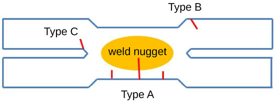
Figure 1.
Categories of LME cracks by AWS [17].
- Type A cracks are located at the weld surface, in the middle of the electrode indentation zone. They may reach the interior of the weld nugget.
- Type B cracks are in the corner of the electrode indentation zone, where the microstructure usually corresponds to the Heat Affected Zone (HAZ).
- Type C cracks are located near the notch tip at the faying surface.
Type A and B are labeled as outer cracks, while type C are labeled as inner cracks.
Although liquid metal embrittlement during resistance spot-welding has been the subject of numerous studies, the exact mechanism behind is not yet fully understood for each type of crack. The commonly adopted scenario states that molten zinc can penetrate rapidly under the surface along grain boundaries during the welding process [13,18], leading to potential embrittlement of the weld. This occurs generally under a limited process window corresponding to the favorable conditions in terms of temperature, stress and strain rate.
It is now well accepted that the coating effect and LME level depend on the steel grade (chemical composition, grain size, metallurgical state) [5,6,7,14,19,20,21,22], but also on the welding configuration (similar/dissimilar stacking of sheets) and welding parameters [23,24] (e.g., welding and holding time as well as electrode force). Consequently, LME is a rather dispersive phenomenon and it is still challenging to anticipate what welding conditions is likely to promote significant LME cracks or in the contrary, guarantee their absence.
Concerning the impact of LME cracks on the mechanical properties, several studies have shown that outer surface cracks do not have any negative influence on welds strengths (neither under quasi-static loading, nor under crash or fatigue testing) [25,26,27,28], this for cracks as long as half the sheet thickness. However, the influence of the inner cracks is still unknown in the literature.
The aim of the present work is to investigate the effect of the different welding parameters on the occurrence of LME cracks during resistance spot-welding of an electro-galvanized 3rd generation advanced high-strength steel. Particular attention is given to the conditions favoring inner cracks, which have been less investigated up to now.
This is carried out in the simple case of a so-called “homogeneous” stacking of the same two sheets. Section 2 presents the material as well as the welding and characterization procedures. Section 3 quantitatively details the measures and observations of LME cracks. The effects of non-standard process parameters are discussed in Section 4 before a short summary of the main conclusions.
2. Materials and Methods
The material investigated was a 3rd generation AHSS with a chemical composition (wt.%) close to 0.2%C, 2.0%Mn, 1.5%Si (Fe: balance). All sheets were 1.56 mm in thickness and electro-galvanized with a 7.5 μm pure Zn layer. This steel exhibits a good combination of strength and ductility (yield strength 1000 MPa, tensile strength 1200MPa and elongation 14% approximately). At room temperature, its microstructure is made of a bainitic matrix containing small quantities of martensite and residual austenite.
Two-sheets resistance spot-welding was performed using the above steel. 150 mm × 50 mm coupons were cut from the steel sheet and welded in the tensile-shear configuration with a 50mm overlap (Figure 2). This homogeneous configuration was chosen despite its tendency to produce less LME cracks than the corresponding heterogeneous configurations of the same material welded with other steel grades or sheet thicknesses [29]. This allows quantification of the intrinsic behavior of the material without the influence of a second sheet with a different stiffness and/or yield strength. The present configuration allows therefore to focus on the influence of welding parameters on the occurrence of LME cracks.
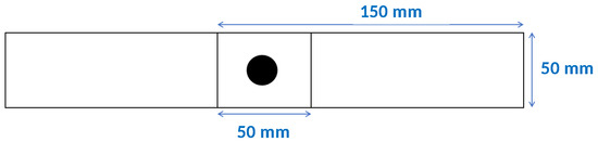
Figure 2.
Tensile-shear specimen.
Following ISO-18278-2 [30], the standard welding parameters for the present weld configuration are: 1400 ms squeezing time, 380ms welding time, 260 ms holding time, 4.5 kN electrode force. This was carried out on a 50 Hz pedestal machine with F1-16-6 mm electrodes. LME literature in the case of resistance spot welds indicates that the most influential parameters for the occurrence of cracks are the welding current intensity, welding time, electrode force, holding time and a misalignment between the electrodes and sheets [15,26].
The welding range was determined for each welding configuration detailed below in Table 1. All the welds investigated in this study were produced at the upper-end of the welding range, i.e., close to the maximum welding current intensity corresponding to the frontier before significant molten metal expulsion during the process. This was shown indeed to promote the occurrence of LME cracks [29]. A special sample holder to be placed between the electrodes was developed in order to control the angle of misalignment between the sheets and the electrodes during welding, as illustrated in Figure 3. When imposed in this study, the misalignment angle was always 5.

Table 1.
Welding conditions in the design of experiments. Non-standard welding conditions in bold.
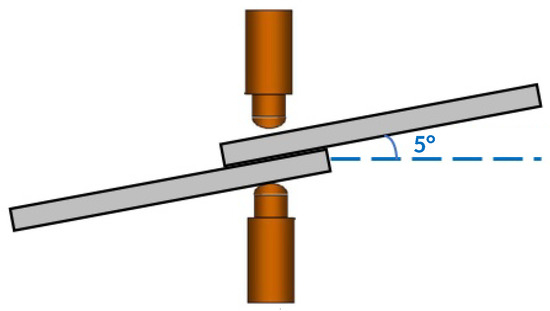
Figure 3.
5° misalignment between the electrodes and the specimens.
The design of experiments corresponding to the variation of welding parameters with respect to the standard is presented in Table 1. Non-standard parameters are highlighted in bold in Table 1. Test 0 corresponds to ISO welding parameters. Test 1 corresponds to ISO welding parameters except for the 5° misalignment. Test 2, 3 and 4 superimpose respectively an increased welding time (760 ms), reduced electrode force (2.0 kN) and reduced holding time (20ms) on top of the misalignment. Test 5 combines all these alterations to the welding parameters. Test 6 suppresses the misalignment from the conditions of Test 5. For conciseness in the identification of the different configurations, the following code is proposed: “M” for misalignment, “T” for the welding time, “F” for the electrode welding force and H for the holding time. Index “0” stands for a standard value of the parameter according to the ISO procedure and “1” for the altered value in the present study to investigate the occurrence of LME cracks.
After welding, all welds were carefully examined using Dye Penetrant Inspection (DPI [31]) first, then using metallographic analysis. DPI (example Figure 4a) was carried out after having chemically removed the electro-galvanized Zn layer, which helps locating outer cracks. Please note that inner cracks at the faying surface cannot be revealed by DPI without destructive inspection by cutting the weld samples.
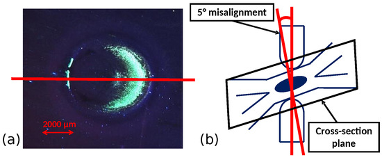
Figure 4.
Dye penetrant inspection (a) and the plane of observation for metallographic analysis (b).
Metallographic analysis was carried out on central cross-sections in the welds based on the DPI observations. The cross-section plane is illustrated in Figure 4b. Metallographic samples were mounted in epoxy resin, mechanically polished down to a 1 micron polishing cloth, then etched in a picric acid solution. The distribution of cracks was then observed and classified with an optical microscope, the length of all visible LME cracks was measured and their number per crack category recorded.
3. Results
Table 2 summarizes a few dimensional characteristics of welds produced in the present experiments, as a consequence of the variation of welding parameters to investigate LME cracking sensitivity. Weld nugget diameters, as measured from the metallographic cross-sections, range from 6.5 mm to 7.5 mm, except for the “M1T0F1H0” and “M0T1F1H1” configurations (respectively Test 3 and Test 6 in Table 1) with a median diameter in the order of 5.6 mm. Electrode indentation depth ranges approximately from 100 μm to 300 μm except for the “M1T1F0H0” configuration (Test 2 with increased welding time and standard electrode force) where it is much higher.
Table 2.
Weld dimensions (mm).
Figure 5 shows typical LME cracks observed in this study in the metallographic cross-sections. Figure 5a illustrates the small outer cracks, ca. 100 μm, obtained for example with ISO welding conditions except for the 5 misalignment of the electrodes (“M1T0F0H0” configuration, Test 1). The effect of misalignment is clearly visible here with the corresponding rotation of the weld nugget with respect to the faying surface and the presence of two asymmetric bumps of electrode indentation (where the small outer cracks are observed). Figure 5b shows an inner crack, ca. 880 μm, obtained in the case of decreased holding time on top of the misalignment of the electrodes (“M1T0F0H1” configuration, Test 4). One can distinguish also two small outer cracks in Figure 5b in addition to solidification defects in the center of the weld. Figure 5c shows a case where both significant inner crack, ca. 910 μm, and outer cracks, more than 400 μm, are observed. It corresponds to a case where all alterations to the welding parameters are combined (“M1T1F1H1” configuration, Test 5).
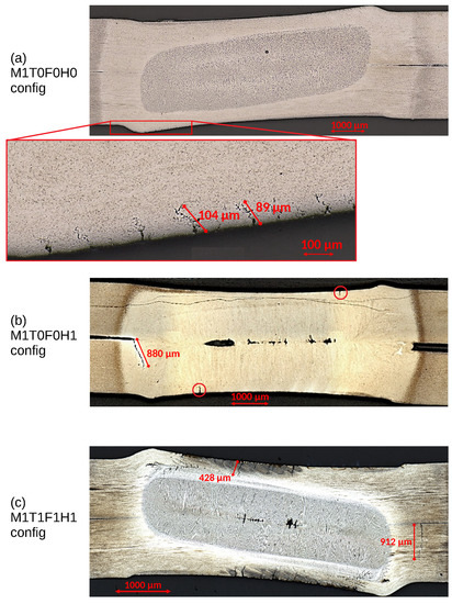
Figure 5.
Metallographic cross-sections. (a) Outer cracks, (b) inner cracks and (c) both.
Quantitative overview of the distributions of inner cracks and outer cracks is presented in Figure 6 for the different welding configurations. This is carried out both in terms of number of cracks (Figure 6b,d) and crack length measurements (Figure 6a,c). Each boxplot in these figures is constructed in such a way that the minimum, 1st quartile, median, 3rd quartile and maximum of the distributions are illustrated graphically in the different welding configurations.
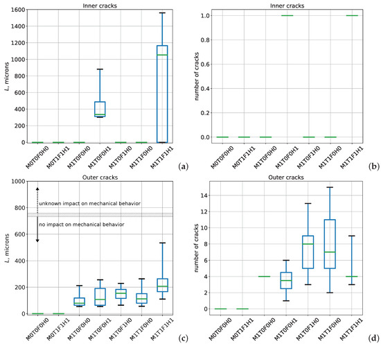
Figure 6.
Liquid metal embrittlement cracks. (a) Inner crack length, (b) number of inner cracks, (c) outer crack length and (d) number of outer cracks.
Figure 6a shows that only two welding configurations produce significant inner cracks, “M1T0F0H1” and “M1T1F1H1” (respectively Test 4 and 5). These correspond to situations under both electrode misalignment and reduced holding time. The observed crack length ranges from several hundreds of microns as in Figure 5b to the total penetration through the sheet thickness (1.56mm) in one case. All other welding configurations do not produce any LME inner crack. One can note from Figure 6b that there is systematically one and only inner crack visible in the weld, when present.
The case of LME outer cracks is rather different. One can see in Figure 6c,d that the configurations without electrode misalignment (“M0T0F0H0” or “M0T1F1H1”) do not produce any outer crack at all. All other configurations produce several small (ca 100 μm) to medium (several hundreds of μm) outer cracks. The number of visible outer cracks in one single metallographic cross-section ranges from a few (1–3) to 15 depending on the welding configuration. One can note that the most severe outer cracks, up to ca 539 μm in length, are obtained for the “M1T1F1H1” configuration (Test 5) where all alterations of the welding parameters are combined. One can see also that the majority of outer cracks, when present, are rather small (less than 250 μm) and that welds presenting numerous outer cracks are not especially those with the most critical ones in size. Please note that the length of all cracks in Figure 6c is below the size of about half the sheet thickness where the absence of effect on mechanical behavior was demonstrated [26,28].
4. Discussion
Liquid metal embrittlement is known to occur under the conjunction of three conditions: high temperature, tensile stresses and the presence of a metal with a melting temperature lower than the base material [32,33]. In galvanized steels, molten zinc-coating may diffuse at the grain boundaries when stressed at high temperature (T > 700 °C) [18]. The results presented above showed that improper control of the welding parameters, namely significant and severe degradation of the welding conditions with respect to the ISO standard [30], might lead to such situation favorable for LME crack occurrence. The present study helps understanding the key factors influencing LME occurrence in the case of a homogeneous welding configuration. One should note that the degraded welding conditions assumed here, with the exception of electrodes misalignment, are clearly improbable in controlled laboratory condition such as that of the present study, and remain improbable even in a “worst case” scenario on industrial BIW assembly lines.
During resistance spot-welding, an increased welding time (“MxT1FxHx” configurations in the present design of experiments) increases the time at elevated temperature in the process. Under given stress conditions imposed by the pressure of the electrodes (potentially misaligned) on top of constrained thermal expansion in the weld, longer welding time therefore increases the effective diffusion distance of Zn in steel, especially at preferential diffusion paths such as grain boundaries. This promotes the occurrence of LME cracks. These are then likely to propagate and become themselves preferential paths for surface zinc diffusion as long as the welding time goes on. As a matter of fact, “M1T1F0H0” configuration (Test 2) in Figure 6d corresponds to a situation with a large number of outer LME cracks, even if they are not the largest ones observed in this study.
The role of electrode force in the formation of LME crack is not straightforward. In the present study, the consequence of a decrease in electrode force is mainly visible through the rather high number of small outer cracks in Figure 6c,d for the “M1T0F1H0” configuration (Test 3). Choi and Liquid et al. [25] studied the effect of electrode force on stress distribution, peak temperature and cooling rate in a TRIP steel spot weld. They found that a decrease in electrode force causes a decrease in cooling rate, but an increase in peak temperature and maximum stress in the weld. Such situation therefore favors the occurrence and propagation of LME cracks. This may seem counter-intuitive as a reduced electrode force decreases the external axial load applied to the weld. Nevertheless, it appears that most critical part of the stress state in the weld arises from the thermal component of loading (constrained thermal expansion) rather than from the external load applied by the electrodes.
Holding time is known to control the cooling rate of resistance spot welds. This is related to the effective role of heat sink played by the water-cooled copper electrodes during the holding time. Short holding time decreases the cooling rate, so that molten zinc remains longer in the liquid state during the cooling step. This allows a longer propagation of LME cracks in the weld. In the present study, one can note that the effect of reduced holding time is especially visible with the long inner cracks generated in the “M1T0F0H1” (Test 4) and “M1T1F1H1” (Test 5) configurations in Figure 6a. Every other configuration with a standard (longer) holding time does not produce any inner crack.
The last but decisive parameter in the present study is the 5° misalignment of electrodes. It appears clearly in Figure 6 that even the worst configuration of welding time, holding time and electrode force does not produce any LME crack (neither inner crack nor outer crack) if the electrodes are properly aligned and perpendicular to the sheets (“M0T1F1H1” configuration, Test 6). The prominent role of electrode misalignment is consistent with previous observations in the literature [15]. The asymmetric positioning of electrodes induces an asymmetric stress field in the weld, favoring LME crack occurrence in the areas of stress concentration. In the case of outer cracks, Figure 5 shows that the latter occur preferentially on the half-side of the weld where the misaligned electrodes produce a “bump” at the surface.
One step further in the quantitative discussion of the effect of welding conditions on the occurrence of LME crack might consist of performing a statistical analysis of the data obtained in the design of experiment. Under the simplest assumption of a linear multivariate model of the maximum crack length or number of crack N as a function of the binarized welding parameters (value “0” for ISO conditions versus “1” for degraded conditions), least square minimization of the model residuals can help interpreting quantitatively the weight and significance of the investigated parameters in the present design of experiment. Equations (1) to (4) recall the form of the investigated models, where M stands for the binarized misalignment, T for the binarized welding time, F for the binarized electrode force and H for the binarized holding time, corresponding to the regression coefficients optimized in the least square procedure:
Model results are summarized in Table 3. values indicate that such linear model explain 89% of variance in the case of the outer cracks, but only 43% in the case of the inner cracks. This goes up to about 80% for the description of the number of cracks for both inner and outer cracks. The large scattering of model residuals in the four models illustrate the limited predictive ability of such linear model when it comes to point by point comparison with experimental measures. However, the global effect of individual variables might still be discussed when looking at the regression coefficients along with their confidence intervals.
Table 3.
Linear model results and significance of the regression coefficients . [95% conf. interval].
Table 3 shows that only the misalignment variable M has a strong and significant effect in the description of outer crack maximum size, . The altered configuration (, i.e., 5 misalignment) brings an average ∼200 μm to , which can also be observed graphically in Figure 6c. Almost the same conclusion applies to the description of the number of outer cracks, , except for a small (and negative) contribution of the altered holding time (, i.e., 20 ms). Concerning inner cracks in Table 3, one can see that their appearance (as indicated by the number of inner cracks ) is mainly affected by the combined effect of both altered holding time and misalignment ( and ), as seen also in Figure 6b. Altered holding time appears as the main contributor to the inner crack size description in the linear model, but the linear model itself is rather inadequate in this case with a poor coefficient of determination . Beyond experimental observations detailed in Section 3 and discussed above, the numbers in Table 3 depict a quantitative overview of the individual effects (and significance) of the different welding parameters in the design of experiment.
Understanding the degraded welding conditions allowing avoidance of LME cracks occurrence, the question arises of their potential influence on the weld mechanical behavior, starting with its load-bearing capacity.
Concerning outer LME cracks, the literature is quite clear on their absence of propagation when subjected to mechanical loading, neither in cross tension [25,26,28], tensile shear [26,28], nor during fatigue [25,26,27,28] or crash loading [26]. This was demonstrated for outer cracks as deep as half the sheet thickness, which is longer than any outer crack found in the present study (see Figure 6c). Spot welds containing outer LME cracks behave in the same way as those which are free of cracks: during cross tension and tensile-shear loading, the failure crack initiates at the notch tip between the two sheets, then propagates through the sheet thickness without interacting with the outer LME cracks [28]. During fatigue loading in tensile-shear, failure initiates also at the notch tip, propagates first through the thickness and then through the base metal, without joining the LME crack [28].
Such experimental evidence does not exist in the literature in the case of inner LME cracks, especially when they appear in the vicinity of the notch tip as in Figure 5b. This is the topic of ongoing investigations.
5. Conclusions
The present study investigated the influence of severely altered resistance spot-welding parameters on the occurrence of LME cracks in a 3rd generation advanced high-strength steel. The following major conclusions can be drawn for the two-sheets homogeneous configuration investigated here:
- Liquid Metal Embrittlement is not only a steel-dependent phenomenon. Indeed, one steel grade could be considered to be non-sensitive to LME in certain conditions while it will be identified as sensitive to LME in other conditions. Welding conditions and environment have a strong impact on the LME occurrence.
- Severe welding conditions such as: electrode misalignment, short holding time, low electrode force and long welding time are the major parameters that influence the most the LME occurrence.
- In this study, an electrode misalignment of 5°, a short holding time of 20 ms, a low electrode force of 2kN and a long welding time of 760 ms constitute a propitious environment for both inner and outer LME cracks.
- The electrode misalignment and the short holding time are responsible for the occurrence of long inner cracks (+137 μm and +412 μm respectively in the linear model).
- Outer cracks are mainly promoted by electrode misalignment (+197 μm in the linear model), with a small and scattered increase in severity under the additional and combined action of the other parameters.
- Standard ISO welding conditions do not promote the occurrence of LME cracks. The application of ISO standard conditions appears as a suitable solution to limit the number and depth of LME cracks in such homogeneous welding configuration.
The investigated conditions were excessively altered as compared to usual practice in industrial BIW assembly lines, where the only uncontrollable parameter is the misalignment of electrodes. The control of all other welding parameters, especially holding time for inner cracks, can guarantee LME-free welds despite potential misalignment.
Future work will address especially the influence of inner LME cracks on the mechanical behavior of the welds.
Author Contributions
Conceptualization, D.F., O.S., S.D., T.D. and Y.B.; methodology, O.S., T.D. and Y.B.; validation, O.S., T.D. and Y.B.; formal analysis, S.D.; investigation, O.S.; resources, T.D. and Y.B.; Writing—original draft preparation, O.S. and S.D.; Writing—review and editing, D.F., T.D. and Y.B.; visualization, O.S. and S.D.; supervision, D.F., S.D., T.D. and Y.B.; project administration, D.F., S.D., T.D. and Y.B.; funding acquisition, D.F., S.D., T.D. and Y.B. All authors have read and agreed to the published version of the manuscript.
Funding
This research was funded by Association Nationale de la Recherche et de la Technologie (CIFRE grant number 2018/0962). The APC was funded by the MATEIS laboratory.
Acknowledgments
The authors acknowledge fruitful discussions with B. Weber and D. Cornette at ArcelorMittal.
Conflicts of Interest
The authors declare no conflict of interest. The funders had no role in the design of the study; in the collection, analyses, or interpretation of data; in the writing of the manuscript, or in the decision to publish the results.
Abbreviations
The following abbreviations are used in this manuscript:
| AHSS | Advanced High-Strength Steels |
| AWS | American Welding Society |
| BIW | Body-In-White |
| DPI | Dye Penetrant Inspection |
| HAZ | Heat Affected Zone |
| LME | Liquid Metal Embrittlement |
| RSW | Resistance Spot-Welding |
References
- Huin, T.; Dancette, S.; Fabrègue, D.; Dupuy, T. Investigation of the Failure of Advanced High Strength Steels Heterogeneous Spot Welds. Metals 2016, 6, 111. [Google Scholar] [CrossRef]
- Yu, J. Adaptive Resistance Spot Welding Process that Reduces the Shunting Effect for Automotive High-Strength Steels. Metals 2018, 8, 775. [Google Scholar] [CrossRef]
- Zuidema, B.K. Introduction to 3rd Generation Advanced High Strength Steels. Available online: https://fdocuments.us/document/introduction-to-3rd-generation-high-strength-high-formability-hshf-for-cold.html (accessed on 7 August 2020).
- Advanced High-Strength Steel Market Size, Share | Growth by 2023. Available online: https://www.alliedmarketresearch.com/advanced-high-strength-steel-market (accessed on 7 August 2020).
- Marder, A. The metallurgy of zinc-coated steel. Prog. Mater. Sci. 2000, 45, 191–271. [Google Scholar] [CrossRef]
- Kim, Y.; Lee, J.; Park, J.; Jeon, S.H. Effect of Si content on wettability of dual phase high strength steels by liquid Zn-0.23 wt.%Al. Met. Mater. Int. 2011, 17, 607–611. [Google Scholar] [CrossRef]
- Oh, M.S.; Kim, S.H.; Kim, J.S.; Lee, J.W.; Shon, J.H.; Jin, Y.S. Surface and cut-edge corrosion behavior of Zn-Mg-Al alloy-coated steel sheets as a function of the alloy coating microstructure. Met. Mater. Int. 2016, 22, 26–33. [Google Scholar] [CrossRef]
- Ertek Emre, H.; Kaçar, R. Resistance Spot Weldability of Galvanize Coated and Uncoated TRIP Steels. Metals 2016, 6, 299. [Google Scholar] [CrossRef]
- Pouranvari, M.; Marashi, S.P.H. Critical review of automotive steels spot welding: Process, structure and properties. Sci. Technol. Weld. Join. 2013, 18, 361–403. [Google Scholar] [CrossRef]
- Russo Spena, P.; Rossi, S.; Wurzer, R. Effects of Welding Parameters on Strength and Corrosion Behavior of Dissimilar Galvanized Q&P and TRIP Spot Welds. Metals 2017, 7, 534. [Google Scholar] [CrossRef]
- Habibi, N.; Sundararaghavan, V.P.U.; Ramazani, A. Experimental and Numerical Investigations into the Failure Mechanisms of TRIP700 Steel Sheets. Metals 2018, 8, 775. [Google Scholar] [CrossRef]
- Jiang, C.; Thompson, A.; Shi, M.; Agashe, S.; Zhang, J.; Zhang, H. Liquid metal embrittlement in resistance spot welds of AHSS steels. AWS Prof. Prog. 2003, 9A. [Google Scholar]
- Beal, C.; Kleber, X.; Fabregue, D.; Bouzekri, M. Embrittlement of a zinc coated high manganese TWIP steel. Mater. Sci. Eng. A 2012, 543, 76–83. [Google Scholar] [CrossRef]
- Choi, D.; Uhm, S.; Enloe, C.; Lee, H.; Kim, G.; Horvath, C. Liquid metal embrittlement of resistance spot welded 1180TRIP steel-effects of crack geometry on weld mechanical performance. Mater. Sci. Technol. 2017, 454–462. [Google Scholar] [CrossRef]
- DiGiovanni, C.; Biro, E.; Zhou, Y. Effect of Liquid Metal Embrittlement cracks on resistance spot weld fracture path. Sci. Technol. Weld. Join. 2018, 24, 218–224. [Google Scholar] [CrossRef]
- Jeon, W.S.; Sharma, A.; Jung, J.P. Liquid Metal Embrittlement of Galvanized TRIP Steels in Resistance Spot Welding. Metals 2020, 10, 787. [Google Scholar] [CrossRef]
- AWS D8.9M:2012 Test Methods for Evaluating the Resistance Spot Welding Behavior of Automotive Sheet Steel Materials. 2012. Available online: https://pubs.aws.org/p/1067/d89m2012-test-methods-for-evaluating-the-resistance-spot-welding-behavior-of-automotive-sheet-steel-materials (accessed on 7 August 2020).
- Jung, G.; Woo, I.S.; Suh, D.W.; Kim, S.J. Liquid Zn assisted embrittlement of advanced high strength steels with different microstructures. Met. Mater. Int. 2016, 22, 187–195. [Google Scholar] [CrossRef]
- Beal, C.; Kleber, X.; Fabregue, D.; Bouzekri, M. Liquid zinc embrittlement of a high-manganese-content TWIP steel. Philos. Mag. Lett. 2011, 91, 297–303. [Google Scholar] [CrossRef]
- Beal, C.; Kleber, X.; Fabregue, D.; Bouzekri, M. Liquid zinc embrittlement of twinning-induced plasticity steel. Scr. Mater. 2012, 66, 1030–1033. [Google Scholar] [CrossRef]
- Vermeersch, M.; De Waele, W.; Van Caenegem, N. LME susceptibility of galvanised welded structures of high strength steels. In Sustainable Construction and Design; Van Wittenberghe, J., Ed.; Ghent University, Laboratory Soete: Ghent, Belgium, 2011; Volume 2, pp. 442–447. [Google Scholar]
- Fernandes, P.J.L.; Jones, D.R.H. Mechanisms of liquid metal induced embrittlement. Int. Mater. Rev. 1997, 42, 251–261. [Google Scholar] [CrossRef]
- Benlatreche, Y. Link between Metallurgy and LME Risk; Technical Report; ArcelorMittal Maizières Research: Maizières-lès-Metz, France, 2017. [Google Scholar]
- Bhattacharya, D. Liquid metal embrittlement during resistance spot welding of Zn-coated high-strength steels. Mater. Sci. Technol. 2018, 34, 1809–1829. [Google Scholar] [CrossRef]
- Choi, D.Y.; Sharma, A.; Uhm, S.H.; Jung, J.P. Liquid metal embrittlement of resistance spot welded 1180 TRIP steel: Effect of electrode force on cracking behavior. Met. Mater. Int. 2019, 25, 219–228. [Google Scholar] [CrossRef]
- Benlatreche, Y. Effect of LME cracks on mechanical performances of spot welds. In Proceedings of the 5th International Conference on Steels in Cars and Trucks, Milan, Italy, 10–14 January 2017. [Google Scholar]
- Rethmeier, M.; Brauser, S.; Schwenk, C.; Noack, T.; Jüttner, S. Influence of welding-induced cracks on the fatigue strength of resistance-spot-welded joints made of high-strength austenitic steel. Weld. Cut. 2012, 11, 232–235. [Google Scholar]
- Benlatreche, Y.; Ghassemi-Armaki, H.; Duchet, M.; Dupuy, T.; Cornette, D.; Carollo, G.; Dietsch, P. Spot-weld integrity of Zn-coated 3rd gen. advanced high strength steels in presence of LME. In Proceedings of the International Automotive Body Congress, Detroit, MI, USA, 20–21 September 2017. [Google Scholar]
- Benlatreche, Y. Design rules to minimize liquid metal embrittlement (LME) cracking. In Joining in Car Body Engineering; Automotive Circle: Hannover, Germany, 2019. [Google Scholar]
- ISO Central Secretary. Resistance Welding—Weldability—Part 2: Evaluation Procedures for Weldability in Spot Welding; Standard ISO 18278-2:2016; International Organization for Standardization: Geneva, Switzerland, 2016. [Google Scholar]
- ISO Central Secretary. Non-Destructive Testing—Penetrant Testing—Part 1: General Principles; Standard ISO 3452-1:2013; International Organization for Standardization: Geneva, Switzerland, 2013. [Google Scholar]
- Kamdar, M. Liquid Metal Embrittlement. Treatise Mater. Sci. Technol. 1983, 25, 361–459. [Google Scholar]
- Di Gabriele, F.; Hojna, A.C.M.; Klecka, J. Behavior of the Steel T91 under Multi Axial Loading in Contact with Liquid and Solid Pb. Metals 2017, 7, 342. [Google Scholar] [CrossRef]


© 2020 by the authors. Licensee MDPI, Basel, Switzerland. This article is an open access article distributed under the terms and conditions of the Creative Commons Attribution (CC BY) license (http://creativecommons.org/licenses/by/4.0/).