Review

Integration of Simulation Driven DfAM and LCC Analysis for Decision Making in L-PBF

1
Research Group of Laser Material Processing, Department of Mechanical Engineering, LUT School of Engineering Science, LUT University, FI-53851 Lappeenranta, Finland
2
Department of Mechanical Engineering, University of Turku, FI-20014 Turku, Finland
*
Author to whom correspondence should be addressed.
Metals 2020, 10(9), 1179; https://doi.org/10.3390/met10091179
Submission received: 30 June 2020 / Revised: 14 August 2020 / Accepted: 27 August 2020 / Published: 2 September 2020
(This article belongs to the Special Issue Additive Manufacturing of Metals with Lasers)

Abstract

:
Laser based powder bed fusion (L-PBF) is used to manufacture parts layer by layer with the energy of laser beam. The use of L-PBF for building functional parts originates from the design freedom, flexibility, customizability, and energy efficiency of products applied in dynamic application fields such as aerospace and automotive. There are challenges and drawbacks that need to be defined and overcome before its adaptation next to rivaling traditional manufacturing methods. Factors such as high cost of L-PBF machines, metal powder, post-preprocessing, and low productivity may deter its acceptance as a mainstream manufacturing technique. Understanding the key cost drivers of L-PBF that influence productivity throughout the whole lifespan of products will facilitate the decision-making process. Functional and operational decisions can yield profitability and increase competitiveness among advanced manufacturing sectors. Identifying the relationships between the phases of the life cycle of products influences cost-effectiveness. The aim of the study is to investigate the life cycle cost (LCC) and the impact of design to it in additive manufacturing (AM) with L-PBF. The article provides a review of simulation driven design for additive manufacturing (simulation driven DfAM) and LCC for metallic L-PBF processes and examines the state of the art to outline the merits, demerits, design rules, and life cycle models of L-PBF. Practical case studies of L-PBF are discussed and analysis of the interrelating factors of the different life phases are presented. This study shows that simulation driven DfAM in the design phase increases the productivity throughout the whole production and life span of L-PBF parts. The LCC model covers the whole holistic lifecycle engineering of products and offers guidelines for decision making.

1. Introduction

Additive manufacturing (AM), known also as 3D printing, is “a process of joining materials to produce parts based on three-dimensional (3D) modelling, usually layer upon layer, as opposed to subtractive manufacturing and formative manufacturing methodologies” [1]. Aerospace, medical, automotive, and service bureaus are key sectors where AM continues to evolve with automotive leading in developments towards full-scale production of AM for benefits such as improved strength and weight functionality [2,3,4,5]. There has not been much precedence in assisting companies in integrating L-PBF to business portfolio, except for a few published studies concerning computer simulation software such as Autodesk, nTopology, SolidWorks, CATIA, E-Stage, and Magics [6,7,8,9]. The scarcity of available literature on the cost-efficiency and lacking reports from industrial scientific sectors currently limit AM industrial full implementation [10,11,12] as published data are often highly case-specific. These challenges are possible to overcome once the key players involved in this modern technological milestone unveil the formation of costs and elaborate the scientific knowhow [13,14]. This paper aims to show how simulation driven design for additive manufacturing (simulation driven DfAM) rules may be utilized with attention to the effect on part quality and accompanying life cycle cost (LCC) to offer better understanding and aid in its adoption. The optimization possibilities for improved profitability and new research areas also are discussed. No study to our knowledge has considered an integrated study of simulation driven DfAM and LCC for cost efficiency.
The basis of this study is the role of simulation driven DfAM in metal L-PBF. This study intends to identify the influence of key cost drivers and processes that can be optimized to control LCC. In the current paper, simulation driven DfAM and LCC will be considered together with the life cycle phases that are susceptible to economic inefficiency of implementation of L-PBF. In addition, other advantages of L-PBF are addressed based on earlier industrial application. The integrated LCC method to L-PBF is presented to highlight the means to optimize energy and raw material consumption, generated waste volume, time, and overall cost throughout the life span of products.

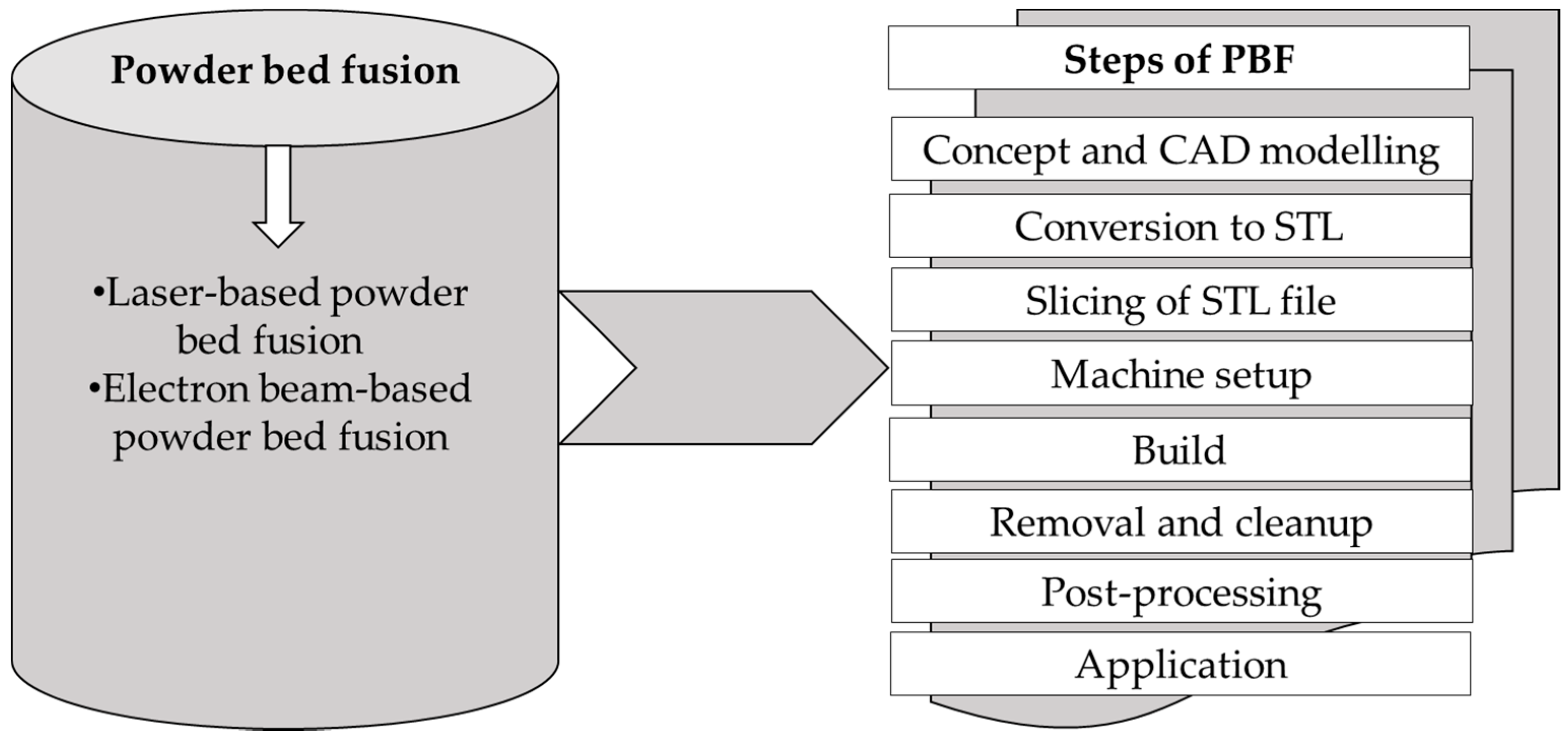
1.1. Laser-Based Powder Bed Fusion

AM methods, including powder bed fusion (PBF) processes, start with the transformation of a 3D model file to STL-format to readable sliced layers for the machine system to machine setup [15]. These files are then exported for necessary modifications and selection of suitable process parameters using special software designed for that specific machine. After actual printing, the platform and built parts are removed from the building chamber and undergo detachment from building platform and subsequent post-processing, which typically involves polishing, coating, machining, or heat treatment according to requirements of the application [2,10,15,16,17]. PBF is an AM technique in which “thermal energy selectively fuses regions of a powder bed” [1]. PBF methods can be categorized into two sub-methods, all following the same layer-wise steps [18,19,20] to create parts as shown in Figure 1 [1,20].
Figure 1 shows the hierarchy of the steps employed to build parts using PBF machine systems. The different can be difference in ways to achieve specific step for each of the building phase. For instance, L-PBF employs a powder reservoir whereas electron beam-based powder bed fusion (EM-PBF) a hopper to feed powder to the building platform. Different techniques of PBF offer advantages that are unattainable with comparable traditional manufacturing methods [6,16,18,19,20,21]. Some of these benefits include the creation of conformal flow channels, reduced manufacturing steps, lattice structures for improved weight, and stiffness. Laser-based powder bed fusion (L-PBF) is one of the subtypes of PBF used to produce structures from powder raw material with the energy of one or more laser beams that selectively melt and fuse the particles at the surface, layer upon layer, in an enclosed process chamber [22].

1.2. Merits and Demerits of L-PBF

L-PBF offers benefits such as manufacturing on-demand, shorter lead times, design flexibility, and ease of design modifications. The application of L-PBF and other AM methods has the potential to improve the existing inefficacies in manufacturing, especially regarding minimizing the amount of source material needed and produced waste [6,10,23]. L-PBF processes eliminate the auxiliary operational and the investment needs such as several manufacturing and assembly steps in different locations [24] and number of essentially needed molds and tools subject to traditional methods [25].
The ability to reduce component weight by creating a customized lattice, net-, and web-like metal structure [26] for L-PBF manufacturing makes the process suitable for dynamic application fields such as aerospace and automotive sectors. This is because all weight reduction improves functionality and thus improves fuel consumption efficiency during the whole service life of the parts [11,15,27,28,29]. Operational costs can be reduced through product design optimization for L-PBF with attention to specific material and equipment that is used to print the parts [30,31,32]. Increasing the throughput of a construction job with shorter lead times will increase productivity [33]. L-PBF costs are largely dependent on the design and manufacturing, therefore, these phases must be optimized in terms of part structural integrity and building process.
Most notably, L-PBF provides a cost-effective means to produce spare parts on time and demand and is usually geographically closer to the user. This reduces inventory and storing costs and simplifies the supply chains while improving the delivery times. Reducing the downtime by manufacturing or repair on demand can also eliminate unwanted costs during the service life of products. Prime examples can be found from the aerospace industry, where unexpected cancellation of planned flights leads to major losses in revenue and accumulation of indirect expenses. Large companies have often heavily invested in spare part acquisition and storage to eradicate or reduce such monetary losses in the occurrence of sudden breakdowns [29]. A major part of L-PBF costs do not have to account for the afore-mentioned aspects, as the price is largely dependent on processing time itself. Hence, any reduction in manufacturing time reduces the overall production cost and results in higher net profitability.
The most common factors discouraging the acceptance of L-PBF are the investment cost of metal L-PBF machine, price of metal powder, lack of standardization, validation, and limitations on the part size [10,34,35,36]. Lack of knowhow of potential of simulation driven DfAM has also a huge effect to this. Several studies [11,12,30,37,38,39,40,41] have however shown that high initial machine costs of L-PBF are justified and have a reasonable payback period. The profits depend on how efficiently machines are utilized over their economic lifespan, the up-time of L-PBF equipment must remain high. Identifying bottlenecks and increasing the yearly output of a machine can be approached with DfAM rules and a simulation software tool, to improve the productivity.
Simulation tools can result in up to 75% productivity [9,29]. With the use of a simulation software, such as nTopology, Fusion 360, e-Stage, and 3DXpert for part optimization during the design phase, possible drawbacks may be identified and managed accordingly before actual production of part. Early detection of potential production bottlenecks aids in the selection of appropriate process parameters. These decrease in time spent on physical printing, scrap rate, and to achieve intended functionality. Following the proposed approach leads to a shorter product development period and enhances part performance [6,8,42]. For instance, redesigning of existing models that are intended for conventional methods involving subtractive machining is the main gateway for unlocking the full potential of L-PBF [43]. Benefits such as lighter weight, reduced lead time, energy, and higher cost efficiency may only be realized through design optimization with simulation driven DfAM of the parts [10,11,30,32,44]. Newest L-PBF machines have the capacity of simultaneous processing with multiple high-power lasers and high-speed scanners enabling increased throughput by saving energy, improved raw material utilization, and time use. The new L-PBF are also equipped with on-line monitoring systems to follow the manufacturing during build of part. Full utilization of the building platform work area is another straightforward way for increasing productivity. The use of skilled personnel enables little-to-no trial and errors, decreasing about 13% in part cost due to human error [29].
Currently, international bodies such as ISO and ASTM are developing the standards and validation methods for metal AM processes. Efforts to improve production volume and part size are ongoing.

1.3. Aim and Purpose of This Study

This study considers the impact of simulation driven DfAM on the LCC of L-PBF manufactured products. The motivation of this study is to provide a deeper understanding of the costs structure of metal L-PBF products and offer recommendations to support the decision-making towards the acceptance of the process. The potential of PBF has been broadly discussed in the studies [11,12,20,30,35,37,38] with the main focus on design and build phases, while the analysis of associated costs has been rarely considered, with attention paid mainly to cost components of machine, materials, and production [16,27,29,45]. There is the need therefore for a systematic model to analyze the cost structure of products made with L-PBF from the idea to end of lifespan. Understanding the cost structure will highlight the associated fixed and variable cost of L-PBF and help assess the impacts of its adoption. The cost structure in L-PBF is composed of the acquisition costs to get the system up and running and the operational costs to keep the system effectively working. This paper is based on a literature survey and focuses on the phases of LCC that characterize products. Understanding the fixed and variable cost of L-PBF allows for efficient choices to be made, for example, through exploiting the full utilization rate of machines. Phases of LCC included in this study are design, manufacturing, use (operation), and end of life (EOL). This study intends to provide the background information of possible costs, design choices, and highlight the means to reduce overall cost. The key cost elements of the different phases are identified with an explanation of their effect to remove the complexities from the decision-making process concerning the application of L-PBF.
This study was executed at LUT University with help of project Metal 3D Innovations (Me3DI) funded by the European Regional Development Fund (grant number, A74131), and project Manufacturing 4.0 (MFG4.0) funded by the Strategic Research Council at the Academy of Finland (grant number, 335992). The Me3DI project (duration 1.9.2018-31.12.2020) aims to establish a knowhow cluster of metal AM to South Karelia (Finland) and is executed by industrial partners and research groups of Steel Structures and Laser Materials Processing and Additive Manufacturing of LUT University. The MFG4.0 project (duration 1.1.2018 to 31.12.2023) aims to investigate how digital manufacturing will change fabrication in Finland and is carried out by the University of Turku, University of Jyväskylä, University of Helsinki, and LUT University.

1.4. Expected Results

This study will highlight the industrial benefits of L-PBF to improve efficiency and cost-effectiveness. As companies continue to adopt to L-PBF, presented case studies will offer exemplary application and assist in making effective and feasible choices for metal based products. The integrated simulation driven DfAM/LCC model will aid in the recognition of an appropriate decision rule for economic evaluations in decision-making. This study will also serve as a guide for analyzing whether investing in the L-PBF process is worthwhile or not to the business portfolio.

2. Materials and Methods

A search in the Web of Science database was conducted within the scope of this review. The phrases used to track the appropriate literature include:
  • Design for additive manufacturing.
  • Life cycle cost in powder bed fusion.
  • Life cycle cost metal additive manufacturing.
  • Design for additive manufacturing in powder bed fusion.
  • Life cycle cost and DfAM in powder bed fusion.
The review data were obtained from four databases, Google Scholar, SpringerLink, Science Direct, ProQuest, and IEEE to validate results. These web bases were chosen as they cover wide and diverse reviews for specific research studies. The review was limited to 15 years (2005–2020) in agreement with the evolution era of AM. LCC studies include definitions outside of this time frame. Figure 2 depicts the outcome of web search with key phrases.
Figure 2 shows that there are gaps in the level of studies relating to LCC and L-PBF. One may argue that the earlier terminologies of this methods could be the reason. Never the less the difference in literature is vast.

2.1. Simulation Driven DfAM in L-PBF

Design for manufacturing and assembly (DFMA) is a conventional systematic method to design and optimize parts, which is produced with traditional methods, such as CNC machining and casting, which aims to increase the manufacturability, quality, performance of products, and to reduce time and cost [18,45,46,47]. DFMA considers traditionally design goals and the constraints set by the applied manufacturing methods to ease manufacturing and assembly.
AM methods differ a lot from the conventional manufacturing processes as the constraints set by tooling and fixtures in conventional processes are non-existing with AM. However, there are specified guidelines and rules to the application of each of the AM methods for effective and successful use in industrial applications. Conventional DFMA can be described as the practice of designing and optimizing a product together with its production system to reduce development time and cost, and increase performance, quality, and profitability [46]. simulation driven DfAM rules substitute the methodological guidelines of DFMA in conventional manufacturing as these production technologies vary in principal level from each others [46,47,48].
Mechanical properties and microstructure of metallic L-PBF parts depend on process parameters (e.g., scan strategies, spot size, layer thickness, amount of energy used, etc.), raw material properties, part geometry, support structures, and environmental factors [2,18,29,49,50,51]. Process optimization approaches are applied to assess the impact of above-mentioned factors on the attainability of desired objectives such as functionality, aesthetics, and efficiency [16,42]. Several studies have highlighted the benefits of using simulation driven DfAM to achieve desired requirements and function [6,7,8,18,42,52,53,54,55]. The scan strategy refers to the type of scan pattern, the number of scan count, and the orientation of scanning paths in respect to each other in specific areas within the single layer. The scan strategy has the potential to impact characteristics such as porosity, microstructure, and formation of support structures and surface roughness of built parts. The selection of processing parameters such as the scan strategy must be done to avoid any defects that might result in undesirable features [2,20,49,56,57,58]. For instance, warping as a common defect in L-PBF [20] is minimized when the randomized scanning pattern is applied, as it prevents the buildup of residual stresses during processing. Another way to avoid warping is by providing sufficient adhesion surface contact between the part and build platform [19]. Rotating the scan pattern is a third way to alter the stress anisotropy resulting from the area localized power distribution within a single deposited layer [49,59].
Studies have shown that material properties can be tailored to achieve process optimization [49,56]. The localized variation of material stiffness can be used to achieve design goals. The material factors affecting the quality of print are: Phase, magnetic functional grading, and grain distribution as controlling parameters to achieve set goals of products. These findings are especially valuable in the context of multi-material AM products development [49,56].
The support structures for metal parts must fulfil the main functions of offering support for initial layers, prevent warping by the anchoring part to the building plate and conducting heat away from the part [19]. This improves the heat exchange capacity to avert reduction of mechanical properties. The use of support structures must be incorporated based on need. The support structures must be designed to have minimal need for material and ease of removal. For instance, initial simulation-based analysis of the support structures performance will reduce the numbers and complexity, being favorable for the physical separation of ready built parts from the base. The amount of work in removing the support structures after the building process can either be simple or complicated, depending whether the overhangs are present and their location on the finished part. Structural supports are mandatory in designs with overhangs regardless of increasing the overall manufacturing complexity. The idea has been formulated to be more specific: “Locating the scan pattern is a third way to alter the stress anisotropy resulting from area localized power distribution within single deposited layer” [49,59]. The chosen method reduces time usage and cost, thus, the designing of parts with the recommended 45° and even 10° overhang angle for self-support structures must be used to eliminate the need for structural supports. Commonly acceptable design rules are shown in Table 1. An exemplary application of these rules is applied to the design part in Figure 3.
The L-PBF process is heavily influenced by case-specific equipment and material, thus a general recommendation such as the given list in Table 1 and Figure 3 may not apply to every L-PBF system [34]. Existing DfAM rules concentrate on promotion or suppressing of a specific geometric shape such as minimum and maximum values of size, inclination angle, allowable bridging distance, etc. [60]. The application of DfAM rules offers an effective and efficient method to design suitable parts for L-PBF manufacturing.

2.2. LCC in Industrial Manufacturing

LCC is comprising associated costs of any process, product, or service in a period between idea generation to the end of life of the part [29]. With LCC, a company is able to carry out an economic evaluation to assess the feasibility of the upcoming project. Part design in ways that consumption of resources and cost-effectiveness of production are accounted for forms a basis for decisions. For instance, reducing the weight of the component is usually one of the main targets that influences the guidelines of design, thereby affecting the decision whether L-PBF is suitable for a specific manufacturing task. The outcome of these evaluations can help companies make decisions to achieve cost-effectiveness utilizing L-PBF [49].
LCC is defined as “the total cost of ownership of machinery and equipment, including its cost of acquisition, operation, maintenance, conversion, and/or decommission” [61]. LCC is also described as “cradle to grave costs summarized as an economics model of evaluating alternatives for equipment and projects” [62]. The life cycle of any system is characterized by cash flow, sales, and profit. Any company aims to identify the possible loopholes in operations and targets them to reduce future risks. The inclusion of operational and EOL associated costs during the designing phase in an LCC analysis will help identify ways of averting future compliance fees or fines. Operational and EOL costs are incurred within the use phase and EOL phase, respectively. It is possible to manufacture lightweight components with L-PBF, thereby reducing fuel consumption while the part is in service. As a result, less emissions are produced when the original design is replaced with lightweight components consequently reducing the fuel consumption in the use phase [29]. Companies are able to save on purchasing environmental quotas and emission certificates as less CO2 is being produced.

2.3. Benefits of LCC Analysis for L-PBF

The design of the product and its performance and life cycle must be carefully planned out already in the beginning of the project [63]. A comprehensive assessment of the various work stages allows maximizing of profitability. The costs structure can be managed within a specific phase and to the entire life cycle [29,49,64]. The inclusion of all associated costs to the LCC helps reduce the single unit price and achieve a fair target cost. The target cost is the final cost of a product or service to achieve to generate the desired level of sales revenue and profit [65]. The designing phase must consider functional and environmental factors. This can lower some future costs such as, operating, maintenance repairs, and environmental clean-up costs at the EOL phase. Different models have been proposed to study LCC [29,46,64,66]. The classification of LCC phases in this study follows the idea of four main phases [64], as shown in Table 2. The costs associated with metal powder acquisition is excluded from this review.
Cost structure in L-PBF is formed on the expenses of equipment acquisition, functionality maintenance, and depreciation costs [46]. The estimation of cost efficiency was performed in study of [46] based on an analysis of the utilization rate of the build platform. This study compared the direct production cost of printing single and multiple parts using L-PBF. The cost of part manufacturing was including energy, raw material, and machine costs. The machine cost structure comprised of purchase cost of machines, its maintenance, and expenses of consumables such as shielding gas. A simultaneous build of similar or dissimilar parts to the fill platform was able to reduce time and cost. It was concluded that energy consumption can be reduced by nearly 81% and production costs by 6% when the platform is utilized at full capacity. It was demonstrated that costs of L-PBF can be optimized, however, the work was limited only to phases of design and manufacturing. For assessing the economic benefits of L-PBF production, entirely, other stages of the product life cycle must be accounted for, including the evaluation of cost-efficacy of EOL.
The cost optimization based on process, material, and design structure for metal based AM has also been studied [16]. The review done in study [16] focused on the crucial aspects (part design and process parameters) concerning controlling the build time and cost. The benefits with the proposed methodology produced a 21% improvement in build time and a 15% reduction of total estimated production cost compared to addressing these themes separately. Processing factors such as beam velocity, laser power, and part optimization effectively influenced energy, material, and time usage. The result of the study showed the importance of integrating process design with topology design to economic efficacy in AM. A summary of the process variables, material properties, and structural design were defined based on the design compliance for cost minimization as Figure 4 shows [16].
The Figure 4 shows the a further categorizing of the production cost of the study [16] into material based (raw materials, material lost during recovering, and recycling) or time-based (production time, energy, and labor)
There are six phases of the product life cycle according to the German standard DIN 60300-3-3 “Dependability management Part 3-3: Application guide Life cycle costing”. The model developed accounts for intrinsic LCC of a product in which cost incurred by both manufacturers and consumers are considered from idea generation to the end of service life. This method is capable to identify cost drivers characterized by each phase. The study [29] has served as a basis for numerous works on the LCC analysis. The proposed method is expanded by assigning the impact factors to each phase and accounts their influence on controlling time and cost of the whole cycle. Figure 5 presents a summary of the LCC model discussed in detail in [29].
The LCC model shown in Figure 5 includes four main cost areas:
  • Initial development and design cost.
  • Manufacturing costs, such as energy, material, etc.
  • Operating costs, such as energy, waste, maintenance, etc.
  • Environmental costs and benefits, such as emissions and residual material.

2.4. Case Studies

The benefits of energy efficiency, improved productivity, and functionality provided by L-PBF to automotive, aerospace, and other applications are explored in studies [20,23,24,26,44,67,68,69,70,71]. These studies highlight the benefits of designing web-like, lattice, conformal flow channels into parts for improving productivity, functionality, aesthetic, etc. aspects and reduced manufacturing steps and time. In studies [20,44,70,71], the benefits of complex internal flow channels, lightweight, net-like structures, function, and part consolidations using various L-PBF methods are presented. The results of such designs are improved stiffness, material efficiency, appearance, and better cost efficiency throughout the life cycle of products [20,60,72]. Figure 6, Figure 7 and Figure 8 show the example cases of using L-PBF to make efficient (lighter, stronger, less assembly required), complex, and customized metal parts with improved functionality and aesthetics.
The optimization solutions presented in Figure 6, Figure 7 and Figure 8 show the usability of L-PBF to lessen the number of parts needed, improve performance and aesthetics without compromising functionality, durability, and service life. Examples presented in Figure 6 and Figure 8 show how L-PBF is useful for integrating multiple parts, thereby reducing the part count. The case shown in Figure 6a resulted in a shorter manufacturing time and fewer steps, part count decreased while its performance was improved by fluid flow optimization. The detail shown in Figure 6b received improvement in a conformal flow channels design. Number of parts (structures shown in Figure 6a,b had 163 and 30 parts) was reduced after redesign to two and one. Manufacturing steps, time, and costs were also reduced. The total time of manufacturing the part shown in Figure 6a was only four months, which is almost one-third (1/3) less than the needed time with traditional methods. The production cost was reduced by 70%, while performance properties were enhanced. Figure 7a illustrates how part optimization may be exploited to improve stiffness in aerospace and automotive applications for making effective and efficient lightweight components. High strength and temperature resistance thermostat covers were economically produced with L-PBF methods for old truck models. Figure 7b presents an example of making spare parts to replace old generation models with a reliably high original equipment manufacturer (OEM) quality. Conformal ribbing is one of the ways to reduce component weight, however this is not possible with classical methods. As shown in Figure 8, existing parts can be redesigned for applying advantages of AM and simultaneously preserving functionality. Novel design reduces the part count and manufacturing steps and time needed for design optimization. Removal of the two mid flanges demonstrates superiority over traditional manufacturing methods, where the part design is typically intended to suit specified manufacturing and assembly rules [44]. In addition to fewer production steps, tools, materials, and shorter manufacturing time provided by L-PBF, functional properties can be preserved or enhanced, and costs minimized.
Resources in L-PBF must be managed to reduce waste and inefficiencies to foster the shift from linear to circular economy. An example of how the Materialise Magics (Materialise, Technologielaan Leuven, Belgium) can help achieve such objectives with attention to reduction of time, raw material usage, scrap, and overall cost in metal AM methods, is shown in Figure 9.
The base of building chamber for the case shown in Figure 9a was 250 × 250 mm. With the appropriate software and qualified personnel, only 10% of the time usually spent in the design stage was used, which translates to savings in cost. Use of simulation software prevents about 75% of defects and failures through virtual simulation before actual production. For instance, time saving of 2 h per build during post-processing adds up to 372 h annually. The number of hours saved in data preparation would equal to 837 h, assuming that each build has a different product design. The 15% re-build ratio, which is a measure of how often the build is repeated during production due to design failures, can be eliminated with the use of simulation. This halves the scrap rate during the manufacturing phase, totalling up to 50% of overall production cost. One example of the detail shown in Figure 9a, is that the efficient design of the parts takes only one-tenth (1/10th) of typically used time and doubles the speed of manufacturing of build phases. One more outcome is a 20% reduction in material consumption depending on defined parameters of each specific case. Figure 9b shows an optimised CAD model. The optimization goal was to improve stiffness by 30% with 40% mass reduction. These goals were effectively achieved using the part design and generative functional design apps of Dassault Systèmes 3dexperience (Dassault Systèmes, Vélizy-Villacoublay, France). The functions and requirements of the design were either preserved or enhanced.

2.5. Integration of Simulation Driven DfAM and LCC of L-PBF

Productivity can be described as a measure of how well input resources are turned into profitable useful outputs in a specified time. Resources include but are not limited to machines, labor, raw materials, investments, energy, etc. [33]. L-PBF offers several means to control outputs with optimized designs which influence materials, energy, time usage, and whole costs. With L-PBF, costs of production may also be altered with the simultaneous building of similar or dissimilar parts from the same material [35,45]. The versatility of L-PBF has potential to increase the efficiency of energy and material usage. Flexibility provided by L-PBF in design stage should reasonably be applied to avoid overcomplicating the model. This will ensure that components fulfill demands set to complexity, weight, functionality, and aesthetics while reducing the manufacturing time and cost.
The possibility to modify the part design for a functional requirement is the main benchmark in L-PBF [11,16]. A model of LCC generated in this study is shown in Figure 10. The LCC model is based on five assumptions:
  • The designed part is applicable in a multiple function.
  • Parts are made with stainless powder.
  • Metal powder is sieved and recycled to be re-used in production.
  • Parts are reusable after the initial usage.
  • At EOL, parts are considered for repairs prior to being recycled.
As it can be seen from Figure 10, design and manufacturing phases are interrelated to the remaining phases of the product life cycle. The literature review established that controlling parameters during the lifespan of components are largely dependent on time, energy, and raw material consumption. These parameters can be controlled during the design phase as denoted by the symbols in Figure 10. The utilisation of simulation software to design optimized components can reduce the rate of failure occurrences. While the physical controlling of material, time, and energy usage is realised during the manufacture phase, they are set already during the design phase. Creating optimised designs and proper support structures can prevent build failures such as distortion and lack of fusion voids. As it can be observed from Figure 10, the consumption of fuel and energy can be controlled during the use phase. The possibility to make effective or efficient design suitable for a specific application can reduce the consumption of these utilities. Lifetime of components is also increased when optimized parts are made. This corresponds to the increased service time for components. The use of L-PBF reduces also downtime in the operational phase with an on-demand and on-time manufacturing option. During EOL, time and energy usage can be reduced if the designing phase was planned to consider the ease of disassembly and related EOL actions. The circularity connecting the different phases denotes that cash continues to flow within the whole system. The design phase allocates for approximately 20% of overall product cost, while around 75% of the manufacturing costs are fixed (e.g., cost of equipment and raw materials). The observed change is obvious when compared to the last decade, when the design cost was making up only 5% of the overall product cost [13].
The simulation driven DfAM in L-PBF primarily can be applied in the activities carried out during the design and build phases, as shown in Figure 11. Actions of these phases need to be optimized to achieve cost efficiency of the entire life span of metallic built components.
The dotted lines in Figure 11 denote some of the characteristic activities which can be targeted to get the needed cost-effectiveness in L-PBF. The designing of parts should be planned to manufacture efficient products and to eliminate defects. The designing and building of optimized and effective structural designs [9,18,39,73] based on a computer driven-design must be preferred to avoid undesirable operational costs. The selection of building parameters must also correlate to cost-effectiveness. The dismantling and sorting of residual material must be considered during the part designing stages as it can directly affect the time and personnel cost after their useful life. Design engineers must understand the implications of part designs during the use and EOL phases in advance to be able to create models that comply with all the phases of life cycle of the products. LCC analysis must be applied to reduce the real and hidden cost. The real cost can be defined as a tangible expense to acquire physical machines and equipment to produce a good or service [74]. The hidden costs can be described as an intangible cost which are unavoidable to the successful running of a company. Examples of these include software tools, training, maintenance, supplies, and upgrades [75].

3. Results and Discussion

A summary of the review scope used in this study (shown in Figure 2) determined that the highest number of published articles are addressing the topic “design for additive manufacturing”, followed by “LCC in metal additive manufacturing”, “metal powder bed fusion”, “design for powder bed fusion”, and “Life cycle cost and simulation driven DfAM in powder bed fusion”. Several of the results were only vaguely related to L-PBF, rather discussing AM methods in general. Concerning LCC, it becomes evident that the topic has gained measurable attention in the manufacturing sector, nevertheless the number of publications addressing metal AM is limited. Several studies considered LCC as part of sustainability or life cycle assessment studies. The majority of the literature involves non-metal materials and AM methods in general. The web search of LCC in PBF or L-PBF costs gave only 167 results from all three databases used, without any findings on the IEEEXplore platform.
The current trend in the state of the art of L-PBF is the prediction of part performance through design improvements and process simulation. The development of L-PBF machines has led to higher production capacity. Simultaneous processing with multiple high power lasers in the work area, high-speed scanners, and an adjustable layer thickness increase the throughput [41,68,76,77]. Use of the simulation driven DfAM software adds value to creation, optimization, and simulation analysis of designs before actual manufacturing. Technical and software advances applied simultaneously minimize defects, labor, material usage, scrap rate, and time needed for production. Support structures and their design form a section of optimization studies and influence the cost of L-PBF. Support structures are currently a highly significant topic for exploratory research.
The cost efficiency and productivity play an important role in the acceptance of L-PBF. The current study highlights the need for costs related studies, as lack of information is hindering adaptation of L-PBF. The initial machine and metal powder costs have been identified as a main deter to its acceptance. Studies on cost-effectiveness in L-PBF are necessary to promote and increase knowledge about the cost benefits that L-PBF presents. In addition to design freedom, the LCC model for L-PBF provides designers, manufacturers, and end-users alike a new market opportunity in metal L-PBF.
The weight cost of raw materials (e.g., powders, filaments, etc.) of AM is up to eight times more than the materials used in conventional methods (e.g., ingots, granulates, etc.). Use of the L-PBF is however justified, as the process facilitates part consolidation [78], lightweight products [20], and has an effective material utilization rate up to 99% [79]. The initial fixed cost of L-PBF system is earned back by a low amount of stand-by time and possibility to produce unique designs. Part consolidation, resulting gains in functionality, and planning out EOL activities decreases expenses as well. Cost-cutting is possible in all of the product life phases through modifications in design, virtual simulation of manufacturing prior to physical printing, and planning the actions for EOL. Monetary savings have so far been most evident in automotive and aerospace sectors, where the weight of re-designed part was reduced by 40% and 70%, respectively resulting in reduced fuel consumption and lower environmental taxes during the exploitation [21,29,80].
The L-PBF process would benefit from studies involving simulation driven DfAM and LCC to highlight the production bottlenecks and methods for controlling the cost in industrial applications. Well informed decision-making in industrial L-PBF outweighs the high price of initial investment by controlling the running costs. Compliance with environmental legislations becomes easier by making sustainable decisions, in addition, possible fines during the use and EOL phases can be avoided. Cost generating issues can be avoided with initial consideration of functional requirements already in the design phase. An assessment of L-PBF with a life cycle engineering quantifies advantages obtainable in energy consumption, maintenance, and environmental impact. The transportation carbon footprint is less with localized manufacturing and reduced logistics needs. A shorter production chain gives companies a competitional advantage by faster delivery times. Unlike traditional manufacturing processes, L-PBF is a highly flexible process allowing swift modifications in design, prior or during production.

4. Conclusions

The aim and purpose of this study is to provide a deeper understanding of life cycle costing (LCC) accumulation in metal part production with laser based powder bed fusion (L-PBF) which is one of most widely used additive manufacturing (AM) technology for metal production. The paper outlines the factors involved in decision-making in choosing the manufacturing method. The geometrical design of the part has a large influence on the overall cost of the product. The LCC analysis of L-PBF equips companies with means needed for developing process models for tracking costs based on the analysis of acquired data. part optimization with simulation driven design for additive manufacturing (simulation driven DfAM) and simulation tools simplifies the choice of processing parameters and results in enhanced functionality and efficiency. AM is known for its design freedom, L-PBF has attracted interest from the industry as the technique allowing the design and manufacture of customized and complex metal products. Current optimized designs suitable for metal L-PBF improve material and energy efficiency utilizing existing L-PBF systems. The inherent problems such as porosity, inhomogeneous microstructure, and deficient surface quality are rapidly improving as a result of applying DfAM rules and IT simulation tools.
The industrial relevance of this article is to provide information for decision-makers to control costs by integrating the design rules with consideration of whole life cycle of the product, not solely on investment costs. This paper aims to contribute to the understanding of cost structure by a holistic evaluation of costs within specific life cycle phases. The main conclusions of simulation driven DfAM and LCC to L-PBF are:
  • Effective application of simulation driven DfAM is an efficient approach to improve design and analysis components for L-PBF.
  • Application of simulation driven DfAM in L-PBF for optimized and energy-efficient designs usually results in an enhanced part functionality and cost-effectiveness.
  • With on-demand and on-time manufacturing, L-PBF reduces operational and inventory costs of companies and gives them competitional advantage.
  • LCC aids in the quantification of costs involved and evaluation of impact of energy, material, infrastructure, personnel, and machine productivity related expenses.
The proposed LCC models shown in Figure 10 and Figure 11 aim to be applicable for testing the effectiveness of L-PBF in an industrial setting. Findings presented in this study offer a holistic method to the LCC analysis in metal L-PBF. For improving the statistical significance, more research on the practical application of simulation driven DfAM to metal L-PBF is needed.

Author Contributions

Methodology, P.N. and H.P.; formal analysis, P.N., H.P., and A.S.; investigation, P.N., H.P., and A.U.; data curation, P.N., H.P., A.S., and A.U.; writing—original draft preparation, P.N., H.P., and A.S.; writing—review and editing, P.N., A.U., and H.P.; visualization, P.N. and A.U.; supervision, H.P., A.S., and A.U.; project administration, H.P., A.U., and A.S.; funding acquisition, H.P., A.U., and A.S. All authors have read and agreed to the published version of the manuscript.

Funding

This research was funded by LUT University through project Metal 3D Innovations (Me3DI) funded by the European Regional Development Fund (grant number, A74131), and project Manufacturing 4.0 (MFG4.0) funded by the Strategic Research Council at the Academy of Finland (grant number, 335992). The Me3DI project (duration 1.9.2018-31.12.2020) aims to establish a knowhow cluster of metal AM to South Karelia (Finland) and is executed by industrial partners and research groups of Steel Structures and Laser Materials Processing and Additive Manufacturing of LUT University. The MFG4.0 project (duration 1.1.2018 to 31.12.2023) aims to investigate how digital manufacturing will change fabrication in Finland and is carried out by the University of Turku, University of Jyväskylä, University of Helsinki, and LUT University.

Acknowledgments

Authors would also like to express gratitude to all partners and companies of the Me3DI project and MFG4.0 project for their contributions during this study.

Conflicts of Interest

The authors declare no conflict of interest.

References

  1. International Organization for Standardization ISO. ASTM52900: 5015-Additive Manufacturing-General Principles-Terminology; ISO/ASME International: Geneva, Switzerland, 2015. [Google Scholar]
  2. Arısoy, Y.M.; Criales, L.E.; Özel, T.; Lane, B.; Moylan, S.; Donmez, A. Influence of scan strategy and process parameters on microstructure and its optimization in additively manufactured nickel alloy 625 via laser powder bed fusion. Int. J. Adv. Manuf. Technol. 2017, 90, 1393–1417. [Google Scholar] [CrossRef]
  3. Bugatti Automobiles, S.A.S. Bugatti—World Premiere: Brake Caliper from 3-D Printer. Available online: https://www.bugatti.com/media/news/2018/world-premiere-brake-caliper-from-3-d-printer/ (accessed on 5 June 2020).
  4. Dunham, S. SmarTech Markets Publishing. Metal Additive ManufacturingTrends. Available online: https://www.smartechanalysis.com/wp-content/uploads/2017/11/dunham_rapid_2015_metal_additive_manufacturing_trends.pdf (accessed on 5 June 2020).
  5. Varotsis, A.B. 3D Printing Trends Q1 2019. 2019. Online Document. Available online: https://www.3dhubs.com/blog/3d-printing-trends-q1-2019/#:~:text=The%20new%203D%20Hubs%203D,%2Dlaunch%20and%20re%2Ddesign.&text=The%203D%20printing%20market%20is,comes%20to%20online%203D%20printing (accessed on 6 June 2020).
  6. Planchard, D. SOLIDWORKS Tutorials, a Step by Step Pproject Based Approach Utilizing 3D Solid Modelling- 2017 Reference Guide; SDC Publications: Mission, KS, USA, 2017. [Google Scholar]
  7. Olhoff, N.; Bendsøe, M.P.; Rasmussen, J. On CAD-integrated structural topology and design optimization. Comput. Methods Appl. Mech. Eng. 1991, 89, 259–279. [Google Scholar] [CrossRef]
  8. Autodesk What Is Generative Design. Tools & Software Autodesk. Available online: https://www.autodesk.com/solutions/generative-design (accessed on 5 June 2020).
  9. Materialise, How to Use Simulation and Reduce Costs in Metal AM Materialise—Innovators you can count on 2020. Available online: https://www.materialise.com/en/resources/software/webinar-recording/how-to-use-simulation-and-reduce-costs-metal-am (accessed on 18 June 2020).
  10. Sculpteo The State of 3D Printing Report: 2020. 2020. Available online: https://www.sculpteo.com/en/ebooks/state-of-3d-printing-report-2020/ (accessed on 5 June 2020).
  11. Mouriaux, F. Motivation, opportunities and challanges of additive manufacturing for space application. In Proceedings of the RUAG Space, Zürich, Switzerland, 6 May 2015. [Google Scholar]
  12. Kretzschmar, N.; Ituarte, I.F.; Partanen, J. A decision support system for the validation of metal powder bed-based additive manufacturing applications. Int. J. Adv. Manuf. Technol. 2018, 96, 3679–3690. [Google Scholar] [CrossRef] [Green Version]
  13. Dowlatshahi, S. The role of logistics in concurrent engineering. Int. J. Prod. Econ. 1996, 44, 189–199. [Google Scholar] [CrossRef]
  14. Tofail, S.A.M.; Koumoulos, E.P.; Bandyopadhyay, A.; Bose, S.; O’Donoghue, L.; Charitidis, C. Additive manufacturing: Scientific and technological challenges, market uptake and opportunities. Mater. Today 2018, 21, 22–37. [Google Scholar] [CrossRef]
  15. Ganesh Sarvankar, S.; Yewale, S.N. Additive Manufacturing in Automobile Industry. Ijrame Publ. 2019, 7, 1–10. [Google Scholar]
  16. Ulu, E.; Huang, R.; Kara, L.B.; Whitefoot, K.S. Concurrent Structure and Process Optimization for Minimum Cost Metal Additive Manufacturing. J. Mech. Des. Trans. ASME 2019, 141. [Google Scholar] [CrossRef] [Green Version]
  17. Etteplan, A.; Hämeenaho, T.; Tölander, H.; Nordenberg, E.; Komi, E.; Rytkönen, I.; Karjalainen, J. Additive Manufacturing Center of Excellence in Finland. REPORT. Available online: https://www.businessfinland.fi/4ada70/globalassets/finnish-customers/02-build-your-network/digitalization/hx-fighter-program/am-center-feasibility-study-2019-nov.pdf (accessed on 1 June 2020).
  18. Gibson, I.; Rosen, D.W.; Stucker, B. Additive Manufacturing Technologies: Rapid Prototyping to Direct Digital Manufacturing; Springer: New York, NY, USA; Berlin/Heidelberg, Germany, 2010; pp. 299–332. ISBN 9781441911193. [Google Scholar]
  19. Varotsis, A.B. Introduction to Metal 3D Printing. 2020. Available online: https://www.3dhubs.com/knowledge-base/introduction-metal-3d-printing/ (accessed on 4 June 2020).
  20. Waller, J. Qualification & Certification of Additively Manufactured Parts for NASA Applications. Nasa Saf. Cent. Webinar. Available online: https://ntrs.nasa.gov/citations/20190000354 (accessed on 1 June 2020).
  21. Metrology.news. Topology Optimization and DMP Combine to Meet GE Aircraft Engine Bracket Challenge. Available online: https://metrology.news/topology-optimization-dmp-meet-aircraft-challenge/ (accessed on 5 June 2020).
  22. Bian, L.; Shamsaei, N.; Usher, J.M. Laser-Based Additive Manufacturing of Metal. Parts: Modeling, Optimization, and Control of Mechanical Properties; Bian, L., Shamsaei, N., Usher, J., Eds.; CRC Press: Boca Raton, FL, USA, 2017; ISBN 9781315151441. [Google Scholar]
  23. Aciturri First Prototypes of Additive Manufacturing Technologies in EWIRA. 2017. Available online: https://www.aciturri.com/en/press-media/news/aciturri-ewira (accessed on 5 June 2020).
  24. General Electric Imagination at Work. Arcam and SLM Solutions acquisitions. 2016. Available online: https://www.ge.com/sites/default/files/ge_webcast_presentation_009062016_0.pdf (accessed on 1 June 2020).
  25. Savolainen, J.; Collan, M. How Additive Manufacturing Technology Changes Business Models?—Review of Literature. Addit. Manuf. 2020, 32, 101070. [Google Scholar]
  26. 3D Natives Ford Produces the Largest Ever 3D Printed Metal Automotive Part. 2019. Available online: https://www.3dnatives.com/en/ford-3d-printed-metal-part-050220195/ (accessed on 5 June 2020).
  27. Baumers, M.; Dickens, P.; Tuck, C.; Hague, R. The cost of additive manufacturing: Machine productivity, economies of scale and technology-push. Technol. Soc. Chang. 2016, 102, 193–201. [Google Scholar] [CrossRef]
  28. Flores Ituarte, I.; Partanen, J.; Khajavi, S.H. Challenges to implementing additive manufacturing in globalised production environments. Int. J. Collab. Enterp. 2016, 5, 232. [Google Scholar] [CrossRef]
  29. Lindemann, C.; Jahnke, U.; Moi, M.; Koch, R. Impact and influence factors of additive manufacturing on product lifecycle costs. In Proceedings of the 24th International SFF Symposium—An Additive Manufacturing Conference, Austin, TX, USA, 12–14 August 2013; pp. 998–1009. [Google Scholar]
  30. Klahn, C.; Meboldt, M. Additive Manufacturing: Cost Factors and Cost Optimization. 2018. Available online: https://www.spotlightmetal.com/additive-manufacturing-cost-factors-and-cost-optimization-a-734518/ (accessed on 5 June 2020).
  31. Keane, P. What is Design for Additive Manufacturing?—Engineers Rule. 2016. Available online: https://www.engineersrule.com/design-additive-manufacturing/ (accessed on 5 June 2020).
  32. Tomlin, M.; Meyer, J. Topology Optimization of an Additive Layer Manufactured (ALM) Aerospace Part. In Proceedings of the 7th Altair CAE Technology Conference, Gaydon, UK, 10 May 2011; pp. 1–9. [Google Scholar]
  33. Sharma, P.C. A Textbook of Production Engineering; S. Chand: New Delhi, India, 1999; ISBN 9788121904216. [Google Scholar]
  34. Brockotter, R. Key Design Considerations for 3D Printing 3D Hubs. Available online: https://www.3dhubs.com/knowledge-base/key-design-considerations-3d-printing/ (accessed on 5 June 2020).
  35. Dutta, B.; Babu, S.; Jared, B. (Eds.) Metal additive manufacturing. In Science, Technology and Applications of Metals in Additive Manufacturing; Elsevier: Amesterdam, The Neatherlands, 2019; pp. 1–10. [Google Scholar]
  36. Yusuf, S.M.; Cutler, S.; Gao, N. Review: The impact of metal additive manufacturing on the aerospace industry. Metals 2019, 9, 1286. [Google Scholar] [CrossRef] [Green Version]
  37. Ruffo, M.; Hague, R. Cost estimation for rapid manufacturing—Simultaneous production of mixed components using laser sintering. Proc. Inst. Mech. Eng. Part. B J. Eng. Manuf. 2007, 221, 1585–1591. [Google Scholar] [CrossRef] [Green Version]
  38. Garetti, M.; Taisch, M. Sustainable manufacturing: Trends and research challenges. Prod. Plan. Control 2012, 23, 83–104. [Google Scholar] [CrossRef]
  39. Salonitis, K.; Salonitis, K. Energy Efficiency of Metallic Powder Bed Additive Manufacturing Processes. In Sustainability in Additive Manufacturing, Environmental Footprints and Eco-Design of Products and Processes, 2nd ed.; Muthu, S.S., Savalani, M.M., Eds.; Handbook Springer Science+Business Media: Singapore, 2016; pp. 1–29. [Google Scholar]
  40. Fried, S. Additive Manufacturing Cost Drivers: 4 Key Considerations. Available online: https://www.nano-di.com/blog/2019-additive-manufacturing-cost-drivers-4-key-considerations (accessed on 5 June 2020).
  41. Gutowski, T.; Jiang, S.; Cooper, D.; Corman, G.; Hausmann, M.; Manson, J.A.; Schudeleit, T.; Wegener, K.; Sabelle, M.; Ramos-Grez, J.; et al. Note on the Rate and Energy Efficiency Limits for Additive Manufacturing. J. Ind. Ecol. 2017, 21, S69–S79. [Google Scholar] [CrossRef]
  42. ProtoCAM Optimized 3D Print Production with Generative Design. Available online: https://www.protocam.com/learningcenter/blog/generative-design/ (accessed on 5 June 2020).
  43. Hällgren, S.; Pejryd, L.; Ekengren, J. (Re)Design for Additive Manufacturing. In Proceedings of the 26th CIRP Design Conference, Stockholm, Swedenm 15–17 June 2016; Elsevier, B.V.: Amsterdam, The Netherlands, 2016; Volume 50, pp. 246–251. [Google Scholar]
  44. Harris, J. 5 Techniques for Lightweighting: Doing More with Less. Available online: https://ntopology.com/blog/2019/10/18/5-techniques-for-lightweighting-doing-more-with-less/ (accessed on 7 July 2020).
  45. Piili, H.; Happonen, A.; Väistö, T.; Venkataramanan, V.; Partanen, J.; Salminen, A. Cost Estimation of Laser Additive Manufacturing of Stainless Steel. In Proceedings of the Physics Procedia, Lappenranta, Finland, 25–28 August 2015; Elsevier, B.V.: Amsterdam, The Netherlands, 2015; Volume 78, pp. 388–396. [Google Scholar]
  46. Thompson, M.K.; Moroni, G.; Vaneker, T.; Fadel, G.; Campbell, R.I.; Gibson, I.; Bernard, A.; Schulz, J.; Graf, P.; Ahuja, B.; et al. Design for Additive Manufacturing: Trends, opportunities, considerations, and constraints. Cirp Ann. Manuf. Technol. 2016, 65, 737–760. [Google Scholar] [CrossRef]
  47. Culleton, M.; Mcdonnell, D.; Shipley, H.; Trimble, D.; Lupoi, R. Dimensional Accuracy and Surface Finish in Additive Manufacturing Design for additive manufacturing (DFAM): The importance of software within selective laser melting (SLM). Euspen. 2017. Available online: https://www.euspen.eu/knowledge-base/AM17114.pdf (accessed on 15 June 2020).
  48. Rosen, D.W. Design for additive manufacturing: A method to explore unexplored regions of the design space. In Proceedings of the 18th Solid Freeform Fabrication Symposium, Austin TX, USA, 6–8 August 2007; pp. 402–415. [Google Scholar]
  49. Brandt, M. Laser Additive Manufacturing: Materials, Design, Technologies, and Applications; Brandt, M., Ed.; Elsevier: Woodhead Publinshing: Duxford, UK, 2016; ISBN 9780081004340. [Google Scholar]
  50. Liu, F.; Lin, X.; Huang, C.; Song, M.; Yang, G.; Chen, J.; Huang, W. The effect of laser scanning path on microstructures and mechanical properties of laser solid formed nickel-base superalloy Inconel 718. J. Alloy Compd. 2011, 509, 4505–4509. [Google Scholar] [CrossRef]
  51. Cherry, J.A.; Davies, H.M.; Mehmood, S.; Lavery, N.P.; Brown, S.G.R.; Sienz, J. Investigation into the effect of process parameters on microstructural and physical properties of 316L stainless steel parts by selective laser melting. Int. J. Adv. Manuf. Technol. 2014, 76, 869–879. [Google Scholar] [CrossRef] [Green Version]
  52. Bendsoe, M.P.; Sigmund, O. Topology Optimization Theory, Methods and Applications—Martin Philip Bendsoe, Ole Sigmund—Google Livres; Springer Science & Business Media: Berlin/Heidelberg, Germany, 2003. [Google Scholar]
  53. Wang, X.; Xu, S.; Zhou, S.; Xu, W.; Leary, M.; Choong, P.; Qian, M.; Brandt, M.; Xie, Y.M. Topological design and additive manufacturing of porous metals for bone scaffolds and orthopaedic implants: A review. Biomaterials 2016, 83, 127–141. [Google Scholar] [CrossRef]
  54. Leary, M.; Merli, L.; Torti, F.; Mazur, M.; Brandt, M. Optimal topology for additive manufacture: A method for enabling additive manufacture of support-free optimal structures. Mater. Des. 2014, 63, 678–690. [Google Scholar] [CrossRef]
  55. Renjith, S.C.; Park, K.; Okudan Kremer, G.E. A Design Framework for Additive Manufacturing: Integration of Additive Manufacturing Capabilities in the Early Design Process. Int. J. Precis. Eng. Manuf. 2020, 21, 329–345. [Google Scholar] [CrossRef]
  56. Doubrovski, E.L.; Tsai, E.Y.; Dikovsky, D.; Geraedts, J.M.P.; Herr, H.; Oxman, N. Voxel-based fabrication through material property mapping: A design method for bitmap printing. Cad Comput. Aided Des. 2015, 60, 3–13. [Google Scholar] [CrossRef]
  57. Rashid, R.; Masood, S.H.; Ruan, D.; Palanisamy, S.; Rahman Rashid, R.A.; Brandt, M. Effect of scan strategy on density and metallurgical properties of 17-4PH parts printed by Selective Laser Melting (SLM). J. Mater. Process. Technol. 2017, 249, 502–511. [Google Scholar] [CrossRef]
  58. Laitinen, V.; Piili, H.; Nyamekye, P.; Ullakko, K.; Salminen, A. Effect of process parameters on the formation of single track in pulsed laser powder bed fusion. In Proceedings of the Procedia Manufacturing, Trondheim, Norway, 27–29 August 2019; Voume 36, pp. 176–183. [Google Scholar]
  59. Carter, L.N.; Martin, C.; Withers, P.J.; Attallah, M.M. The influence of the laser scan strategy on grain structure and cracking behaviour in SLM powder-bed fabricated nickel superalloy. J. Alloy. Compd. 2014, 615, 338–347. [Google Scholar] [CrossRef]
  60. Star Rapid The Top 7 Design Tips for 3D Metal Printing. Available online: https://www.eurekamagazine.co.uk/design-engineering-blogs/the-top-7-design-tips-for-3d-metal-printing/164735/ (accessed on 4 June 2020).
  61. SAE. Reliability and Maintainability Guideline for Manufacturing Machinery and Equipment; SAE International: Warrendale, PA, USA, 1999; ISBN 076800473X. [Google Scholar]
  62. Barringer, H.P. A Life Cycle Cost Summary; Barringer & Associates, Inc.: Perth, Australia, 2003. [Google Scholar]
  63. Umeda, Y.; Fukushige, S.; Kunii, E.; Matsuyama, Y. LC-CAD: A CAD system for life cycle design. Cirp Ann. Manuf. Technol. 2012, 61, 175–178. [Google Scholar] [CrossRef]
  64. Garrett, K. Target Costing and Lifecycle Costing ACCA Global. Available online: https://www.accaglobal.com/gb/en/student/exam-support-resources/fundamentals-exams-study-resources/f5/technical-articles/target-lifestyle.html (accessed on 5 June 2020).
  65. WebFinance Inc. What Is Committed Cost? Definition and Meaning—BusinessDictionary.com. Available online: http://www.businessdictionary.com/definition/committed-cost.html (accessed on 5 June 2020).
  66. Dhillon, S.B. Life Cycle Costing: Techniques, Models, and Applications; Routlesge: London, UK, 1989; Volume 33. [Google Scholar]
  67. Mercedes-Benz Mercedes-Benz Replacement Parts from the 3D Printer. Available online: https://www.mercedes-benz.com/en/classic/classic-service-parts/next-generation-mercedes-benz-replacement-parts-from-3d-printer/ (accessed on 5 June 2020).
  68. Chalmers University of Technology Increased Productivity of Laser Powder Bed Fusion Chalmers. Available online: https://www.chalmers.se/en/centres/cam2/cases/Pages/case-productivity-of-laser-powder-bed-fusion.aspx (accessed on 5 June 2020).
  69. Blain, C. Additive Manufacturing Can Reduce Part Counts Significantly Design News. Available online: https://www.designnews.com/automation-motion-control/additive-manufacturing-can-reduce-part-counts-significantly/32852757559475 (accessed on 5 June 2020).
  70. 3D Systems Corporation (DLR) Designs Liquid Rocket Engine Injector with 3D Systems. Case study. Available online: https://www.3dsystems.com/customer-stories/german-aerospace-center-dlr-designs-liquid-rocket-engine-injector-3d-systems (accessed on 10 July 2020).
  71. Daimler AG Premiere at Mercedes-Benz Trucks: New from the 3D Printer: The First Spare Part for Trucks Made of Metal. Available online: https://media.daimler.com/marsMediaSite/instance/ko.xhtml?oid=23666435&filename=Premiere-at-Mercedes-Benz-Trucks-New-from-the-3D-printer-the-first-spare-part-for-trucks-made-of-metal&ls=L2VuL2luc3RhbmNlL2tvLnhodG1sP29pZD0yMzY2NjQzNSZyZWxJZD0xMDAxJmZyb21Pa (accessed on 15 July 2020).
  72. Ponche, R.; Kerbrat, O.; Mognol, P.; Hascoet, J.Y. A novel methodology of design for Additive Manufacturing applied to Additive Laser Manufacturing process. Robot. Comput. Integr. Manuf. 2014, 30, 389–398. [Google Scholar] [CrossRef] [Green Version]
  73. AM Sub-Platform AM SRA. Final Document 2014 Additive Manufacturing: Strategic Research Agenda. 2014. Available online: https://www.rm-platform.com/linkdoc/AM%20SRA%20-%20February%202014.pdf (accessed on 4 June 2020).
  74. InvestorWords What Is Real Cost? Definition and Meaning. Available online: http://www.businessdictionary.com/definition/real-cost.html# (accessed on 13 August 2020).
  75. WebFinance Inc. What Is Hidden Cost? Definition and Meaning—BusinessDictionary.com. Available online: http://www.businessdictionary.com/definition/hidden-cost.html (accessed on 13 August 2020).
  76. Khorasani, A.M.; Gibson, I.; Veetil, J.K.; Ghasemi, A.H. A review of technological improvements in laser-based powder bed fusion of metal printers. Int. J. Adv. Manuf. Technol. 2020, 108, 191–209. [Google Scholar] [CrossRef]
  77. Lindsay Luminoso Multi-Laser Additive Manufacturing. Available online: https://www.canadianmetalworking.com/canadianmetalworking/article/metalworking/multi-laser-additive-manufacturing (accessed on 18 June 2020).
  78. Diegel, O.; Nordin, A.; Motte, D. (Eds.) Guidelines for Part Consolidation. In A Practical Guide to Design for Additive Manufacturing; Springer: Singapore, 2019; pp. 79–84. ISBN 978-981-13-8281-9. [Google Scholar]
  79. Nyamekye, P.; Piili, H.; Leino, M.; Salminen, A. Preliminary Investigation on Life Cycle Inventory of Powder Bed Fusion of Stainless Steel. In Proceedings of the Physics Procedia, Aalborg University in Denmark, 22–24 August 2017; Volume 89, pp. 108–121. [Google Scholar]
  80. Griffiths, L. Interview: How Briggs Automotive Company Re-Engineered a Supercar with Generative Design and 3D Printing—TCT Magazine. Available online: https://www.tctmagazine.com/3d-printing-news/bac-interview-supercar-3d-printing-generative-design/ (accessed on 4 June 2020).
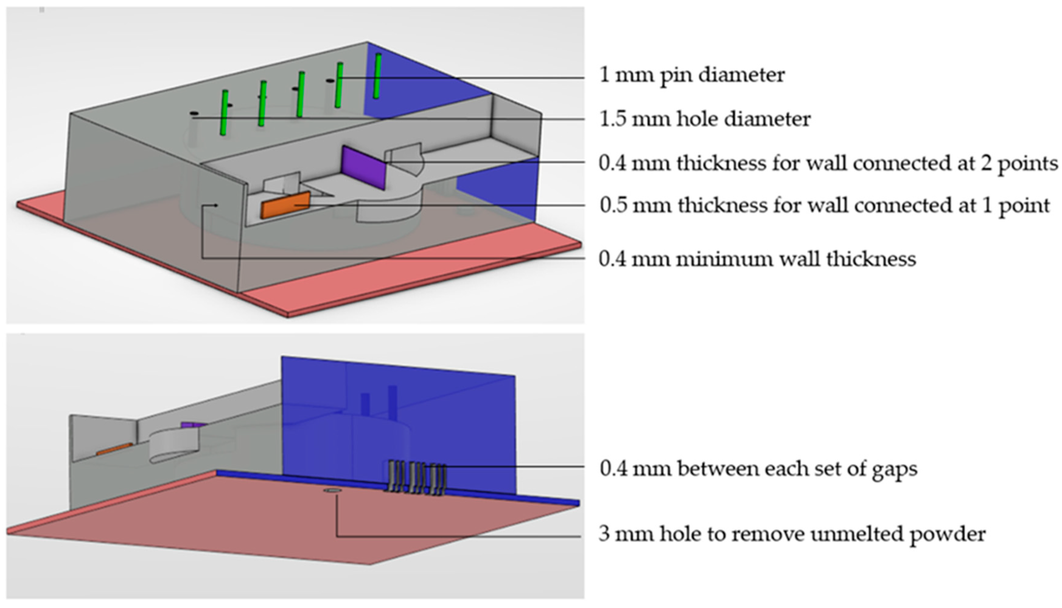
Figure 1. Schematic representation of powder bed fusion (PBF) systems and steps of manufacturing [1,20].
Metals 10 01179 g001
Figure 2. Representation of the web data base and number of literature hits between 2005–2020 related to this review.
Metals 10 01179 g002
Figure 3. Example of applying DfAM geometrical recommendations in the part design.
Metals 10 01179 g003
Figure 4. Schematic of concurrent method to reduce cost in metal additive manufacturing (MAM). Adapted from [16].
Metals 10 01179 g004
Figure 5. Schematic of the LCC model in the study of Lindemann et al. (2013). Adapted from [29].
Metals 10 01179 g005
Figure 6. Example of metal aerospace designed liquid fuel injectors (a) by NASA, reproduced from [20,70] and (b) three-dimensional (3D) systems reproduced from [70] with permission from 3D systems.
Metals 10 01179 g006
Figure 7. Representation of optimized (a) titanium spacecraft bracket, reproduced from [44] with permission from nTolology and (b) aluminum/silicon printed thermostat covers attached to the build platform. Reproduced from [71] with permission from Daimler AG.
Metals 10 01179 g007
Figure 8. Case studies including. (a) classical assembly of pipes and (b) redesigned pipe assembly as consolidated a pipe assembly with conformal ribbing. Reproduced from [44] with permission from nTolology.
Metals 10 01179 g008
Figure 9. Example of (a) production cost reduction and (b) optimized design using a simulation-driven preventive method. Data in (a) from [9].
Metals 10 01179 g009
Figure 10. Representation of the LCC model for products made with L-PBF showing interrelations between phases based on time, energy, metal powder, and cash flow.
Metals 10 01179 g010
Figure 11. Schematic of activity-based cost structure breakdown for L-PBF of metallic components.
Metals 10 01179 g011
Table 1. Design rules based on geometrical features suitable for metallic laser PBF (L-PBF). Adapted from [34,60].
FeatureDfAM AspectRecommended Minimium Dimension
1.SupportsThe maximum angle a wall can be printed without requiring supportAlways required
2.Supported wallsConnected to other structures on at least two sides0.4 mm
3.Unsupported wallConnected to the rest of the part on only one side0.5 mm
4.HolesThe minimum diameter of hole printableØ 1.5 mm
5.Pin diameterThe minimum diameter of a pin can be printed at 1 mm
6.Minimum featuresThe recommender minimum size of a feature to ensure it will not fail to print0.6 mm
7.Wall thicknessThe minimum wall thickness to ensure a successful print for most materials0.4–0.5 mm
8.Escape holesThe minimum diameter of escape hole for removal of build material3–5 mm
9.Gap sizeAcceptable gap widths≥0.4 mm
(dependent on laser spot)
Table 2. Representation of life cycle cost (LCC) phases of L-PBF manufacturing.
PhasesType of Cost
1. Design 1research, development, design
2. Manufacturing (Build)machines, material, labor, post-processing overheads, depreciation, test and validate
3. Operation (Use)fuel cost, warrant claims, maintenance, CO2 charges/fines
4. EOLenvironmental clean-up, reuse, remanufacture, recycling, disposal, and decommissioning
1 Adapted from Lindemann et al. and Garrett [29,64].

