Article

Effect of Roller Quenching on Microstructure and Properties of 300 mm Thickness Ultra-Heavy Steel Plate

The State Key Laboratory of Rolling and Automation, Northeastern University, P.O. Box 105, No. 11, Lane 3, Wenhua Road, Heping District, Shenyang 110819, China
*
Author to whom correspondence should be addressed.
Metals 2020, 10(9), 1238; https://doi.org/10.3390/met10091238
Submission received: 2 August 2020 / Revised: 1 September 2020 / Accepted: 9 September 2020 / Published: 15 September 2020

Abstract

:
In this paper, a 300 mm thickness ultra-heavy steel plate was selected as the research object. In addition, special roller quenching equipment and a new testing method were used to measure the quenching temperature curve at different positions of the steel plate. The relationships and corresponding interaction mechanisms between cooling rate, microstructure, and mechanical properties of an ultra-heavy steel plate during roller quenching were investigated. The results indicated that the cooling rate, strength, hardness, and impact energy decreased gradually along the thickness direction of the plate, while the cooling rate, average grain size, and mechanical properties were relatively uniform with little change along the length direction of the plate. The experimental results provide an effective way to further control the microstructure and properties of ultra-heavy steel plates during roller quenching.

1. Introduction

Ultra-heavy steel plates with large single weight and large section are important basic materials used in the fields of marine engineering, energy chemical industry, hydropower, nuclear power, and construction machinery [1,2]. Quenching is a common heat treatment process in the production of ultra-heavy plates. However, due to their large thickness, a significant temperature gradient from the surface to the center may appear during quenching, which can lead to a significant cross-section effect, causing great differences in the microstructure and properties of an ultra-heavy steel plate [3,4]. Therefore, it is of great significance to investigate the cooling rate and temperature gradient of ultra-heavy plates during quenching, in order to improve the quenching process and the resulting uniformity of the material microstructure and properties.
At present, the research on quenching is based on simulation analyses using finite element software platforms. Carlone et al. [5] modelled, simulated, and analyzed the transient temperature field and microstructure transformations related to quenching of a eutectoid plain carbon steel. Woodard et al. [6] proposed a new model and an efficient procedure based on the finite element method (FEM) to calculate the temperature, microstructure, and hardness distributions developed in eutectoid carbon steels during quenching. Yang et al. [7] simulated the quenching process of an A357 aluminum alloy cylindrical bar with a diameter of 80 mm using FEM. Li et al. [8] developed an FEM software for quenching. Kang et al. [9] developed a finite element program to investigate design parameters for the quenching process. Şimşir et al. [10] developed a 3D FEM model to predict temperature history, evolution of microstructure, and internal stresses during quenching. However, the results obtained by the computational models often deviate from the actual situation, which makes such approaches insufficient for guiding the production and adjusting the microstructure and properties of ultra-heavy steel plates. Therefore, the direct and accurate measurement of the temperature gradient and cooling rate in the quenching process of ultra-heavy steel plates has become the key to developing new equipment and technology for roller quenching, formulating scientifically reasonable quenching processes, and improving the quality of heat treatments.
In this paper, a 300 mm thickness ultra-heavy steel plate was selected as the research object. In addition, special roller quenching equipment (the first one in the world) and a new testing method were used to measure the quenching temperature curves at different positions of the steel plate. The relationships and corresponding interaction mechanisms between cooling rate, microstructure, and mechanical properties of an ultra-heavy steel plate during roller quenching were investigated. The experimental results provide an effective way to further control the microstructure and properties of ultra-heavy steel plates during roller quenching.

2. Material and Experimental Procedure

2.1. Experimental Material

The experimental material was EH36 steel, which, after hot rolling, is commonly used in ships. Its chemical composition is as follows (mass fraction %): 0.119 C, 0.035 Cu, 0.247 Si, 1.24 Mn, ≤0.009 P, ≤0.001 S, 0.022 Cr, 0.013 Mo, 0.288 Ni, 0.04 V, and 0.019 Nb. The steel plate had a thickness of 300 mm, a width of 2215 mm, and a length of 7430 mm. After punching the steel plate, a K-type sheathed thermocouple (Ø4 mm) was inserted into the hole.
Due to the special layout of heat treatment furnace and quenching machine for ultra-heavy steel plate, the temperature recorder needs to go through a long heating and holding time with the steel plate and swing cooling process during quenching, which requires the temperature recorder to have the characteristics of high temperature resistance and water resistance. The traditional infrared temperature measurement method can only measure the surface temperature of steel plate but cannot measure the internal temperature of the steel plate. Moreover, because the water flow blocked the infrared rays during quenching, it cannot measure the temperature change of steel plate during quenching. The temperature measurement by pulling wire was to set the temperature measurement point in the first steel plate and placed the temperature recorder on the second steel plate [11]. The temperature measurement point was connected with the temperature recorder by thermocouples, and the two steel plates were connected by connecting rod. Although this method can measure the internal heating temperature of the steel plate, the steel plate cannot swing during the measurement of quenching process, and the temperature recorder on the second steel plate cannot be drenched. When the first steel plate passed, the cooling water was turned off immediately. This method cannot meet the requirements of swing cooling process of ultra-heavy steel plate during quenching. In this paper, a new method of temperature measurement was proposed, which can meet the requirements of the temperature recorder to go through a long heating and holding process with the steel plate and swing cooling process during quenching.
The proposed testing method was as follows: a K-type temperature recorder connected with the thermocouple was placed at a corner of the steel plate to record the real-time temperature at each measurement point. The nano heat insulation board (WH Thermal Technology, Shanghai, China) was added around the temperature recorder to resist high temperature. The board had a thickness of 20 mm, a width of 400 mm, and a length of 600 mm. The maximum service temperature of the board was 1000 °C. The water baffle and sealant were added on the temperature recorder to seal water. The temperature recorder moved together with the test steel plate, enabling the measurement of the change in steel plate temperature during the entire quenching process in real time, following the complex motion patterns of the steel plate that included acceleration, deceleration, and swing.
The locations of the temperature measurement points in the steel plate are illustrated in Figure 1. Temperature measurement points P1, P2, and P3 were located at the tail of steel plate, points P4 and P5 were located at the middle of steel plate, and points P6, P7, and P8 were located at the head of the steel plate. The three temperature measurement points located at the head (P6, P7, and P8) and tail (P1, P2, and P3) of the steel plate were arranged along the thickness direction at 3.5 mm, 75 mm (1/4-thickness), and 150 mm (1/2-thickness) below the surface of the steel plate. The two temperature measurement points located in the middle of the steel plate (P4 and P5) were arranged along the thickness direction at 75 mm (1/4-thickness) and 150 mm (1/2-thickness) below the surface of the steel plate. Consequently, there were 8 measurement points in total with a diameter of 5 mm and a depth of 100 ± 0.5 mm.

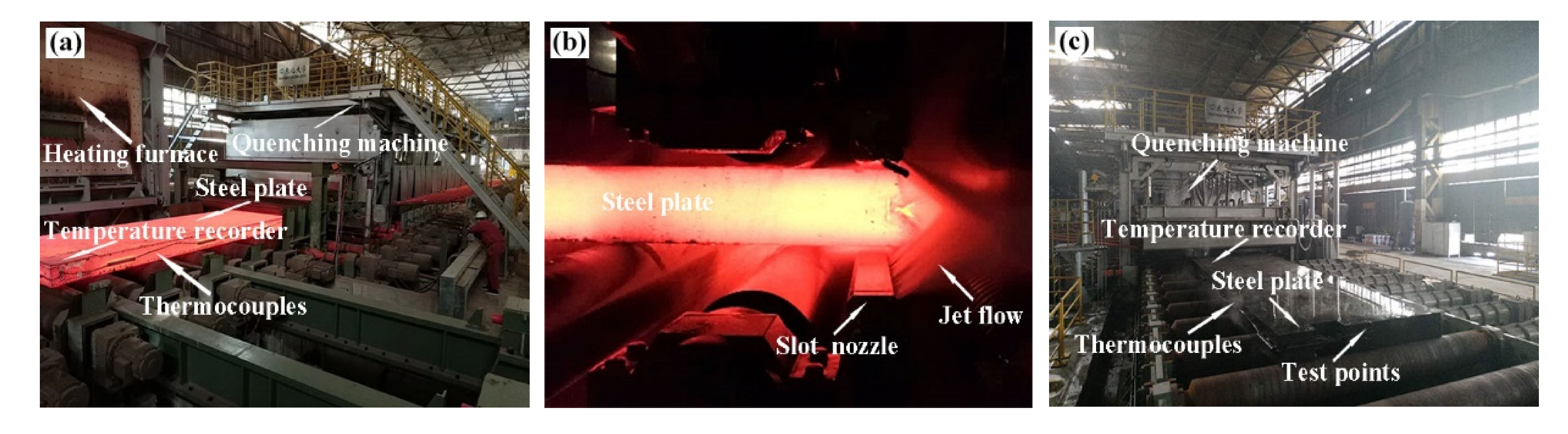
2.2. Experimental Device and Parameters

The experimental equipment and different phases of the quenching process are demonstrated in Figure 2. The total length of the roller quenching machine was 20 m. The inlet side of the machine with a length of 4 m was the high-pressure cooling area (Zone I), and the outlet side of the machine with a length of 16 m was the low-pressure cooling area (Zone II). The speed of the steel plate was controlled by the roller table arranged symmetrically up and down. The steel plate was heated in the heating furnace to 915 ± 5 °C and heated and insulated for 12 h. Then, it was placed on the conveying roller table by an external mechanical arm and passed through the quenching area at a certain speed. The set pressure in Zone I was 0.8 MPa, and the flow rate was 4200 m3 h−1, while the set pressure in Zone II was 0.4 MPa, and the flow rate was 5200 m3 h−1. The steel plate was swung in Zone II after 1 h, and then, it was transported out by the roller table. Finally, the microstructure and mechanical properties at the 8 temperature measurement points were analyzed.

2.3. Microstructural Characterization

The metallographic specimens were first mechanically ground and polished, then etched with 4% nitric acid alcohol solution for about 20 s, and finally, their microstructures were observed by OLYMPUS BX53 metalloscope (OLYMPUS Inc., Kyoto, Japan) and a Zeiss Ultra-55 scanning electron microscope (SEM) (Carl Zeiss AG, Jena, Germany). The crystallographic characterizations were performed using an SEM equipped with an Electron Backscatter Diffraction (EBSD) system and CHANNEL 5 software (version; 5.0.9.0, OXIG Co. Ltd., Oxford, UK). Standard transmission electron microscopy (TEM) 3 mm diameter thin foils were first ground to 40 μm thickness, followed by electro-polishing in a solution of 8% perchloric acid and 92% alcohol at −20 °C in a twin-jet electro-polisher (Struers Inc., Copenhagen, Denmark), and finally, they were examined by a FEI Tecnai G2 F20 TEM (FEI Co. Ltd., Hillsboro, OR, USA) at an accelerating voltage of 200 kV.

2.4. Mechanical Properties Characterization

Hardness was measured using a FM-700 hardness tester (Future-Tech, Kawasaki, Japan), and the results were presented as an average of three measurements for each test. Tensile testing specimens, 5 mm in diameter and 50 mm in length, were obtained along the direction perpendicular to the rolling direction. Tensile tests were conducted at room temperature at a crosshead speed of 1 mm/min using a AG-Xplus 100 KN testing machine (Shimadzu, Kyoto, Japan). Standard impact test specimens (10 × 10 × 55 mm) with a v-notch parallel to the rolling direction were obtained, and impact tests were conducted at −40 °C using an Instron Dynatup 9200 series instrumented drop weight impact tester (Instron, Norwood, MA, USA). Toughness results were also presented as an average of three measurements for each test. Finally, the fracture surface of the impact samples was observed using a Zeiss Ultra 55 SEM (Carl Zeiss AG, Jena, Germany).

3. Results and Discussion

3.1. Analysis of Cooling Curve

As it can be seen in Figure 3a, when the ultra-heavy steel plate entered Zone II from Zone I, the quenching temperature curve exhibited an increase in temperature. The temperature increase at the upper surface was 145–208 °C and at the 1/4-thickness was 34–49 °C, while no temperature increase was observed at the 1/2-thickness. The increase in temperature decreased with increasing plate thickness. In a short time after rapid cooling, due to the temperature difference along the thickness, the heat should be transferred from the center of the plate to the surface; thus, the surface temperature increased. At the same time, there was also heat exchange between the steel plate surface and the environment, which caused a decrease in the surface temperature. It can be seen in Figure 3b that the temperature gradient between the 1/4-thickness and the steel plate surface increased rapidly to the maximum value in Zone I. The temperature gradient of the steel plate head (P6–P7) reached the maximum value of 7.13 °Cmm−1 after 403 s, while that of the tail (P1–P2) reached the maximum value of 8.26 °Cmm−1 after 491 s—both decreased significantly and continuously in Zone II. The temperature gradient between the 1/2-thickness and 1/4-thickness of the steel plate increased gradually in Zone I and reached the maximum value after entering Zone II. The temperature gradient of the steel plate head (P7–P8) reached the maximum value of 1.71 °Cmm−1 after 775 s, that of the middle part (P4–P5) reached the maximum value of 2.26 °Cmm−1 after 854 s, while that of the tail (P2–P3) reached the maximum value of 2.78 °Cmm−1 after 868 s; all decreased continuously. In Zone I, the temperature gradient of the steel plate can be achieved by a large amount of water and a high water pressure. In Zone II, the continuous cooling capacity of the steel plate can be strengthened to maintain a large degree of supercooling on the surface and provide a balance between surface heat exchange and internal heat conduction.
As it can be observed in Figure 3c, in the high temperature range (800–400 °C), at the upper surface of the steel plate, the cooling rate was 3.96 °Cs−1 at the head (P6) and 4.08 °Cs−1 at the tail (P1); at the 1/4-thickness position of the steel plate, it was 0.68 °Cs−1 at the head (P7), 0.65 °Cs−1 at the middle (P4), and 0.64 °Cs−1 at the tail (P2); at the 1/2-thickness position of the steel plate, it was 0.58 °Cs−1 at the head (P8), 0.58 °Cs−1 at the middle (P5), and 0.54 °Cs−1 at the tail (P3). In Figure 3d, it can be observed that in the low-temperature range (400–200 °C), at the upper surface of the steel plate, the cooling rate was 1.23 °Cs−1 at the head (P6) and 1.27 °Cs−1 at the tail (P1); at the 1/4-thickness position of the steel plate, it was 0.26 °Cs−1 at the head (P7), 0.21 °Cs−1 at the middle (P4), and 0.18 °Cs−1 at the tail (P2); at the 1/2-thickness position of the steel plate, it was 0.17 °Cs−1 at the head (P8), 0.19 °Cs−1 at the middle (P5), and 0.16 °Cs−1 at the tail (P3). The cooling rate decreased gradually along the thickness direction of the plate, while it was relatively uniform with little changes along the length direction of the plate.

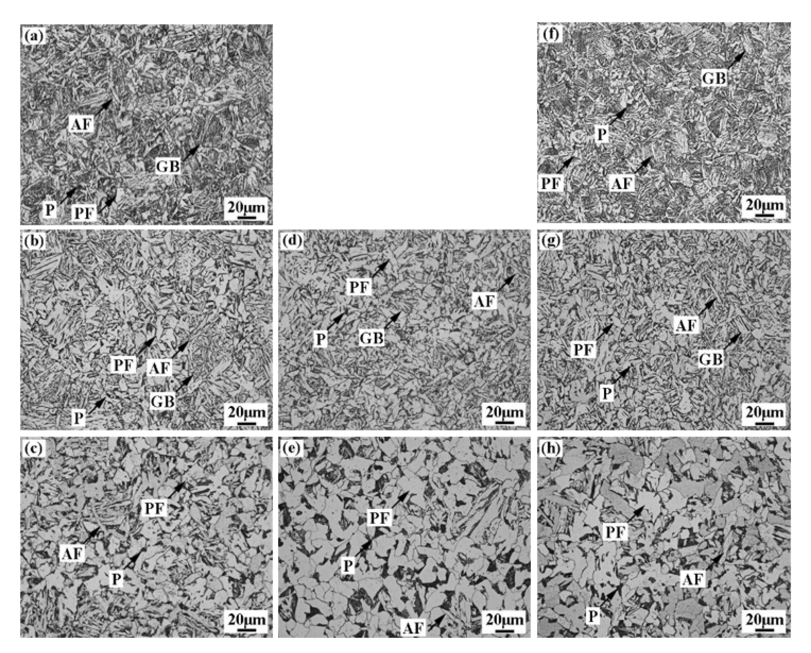
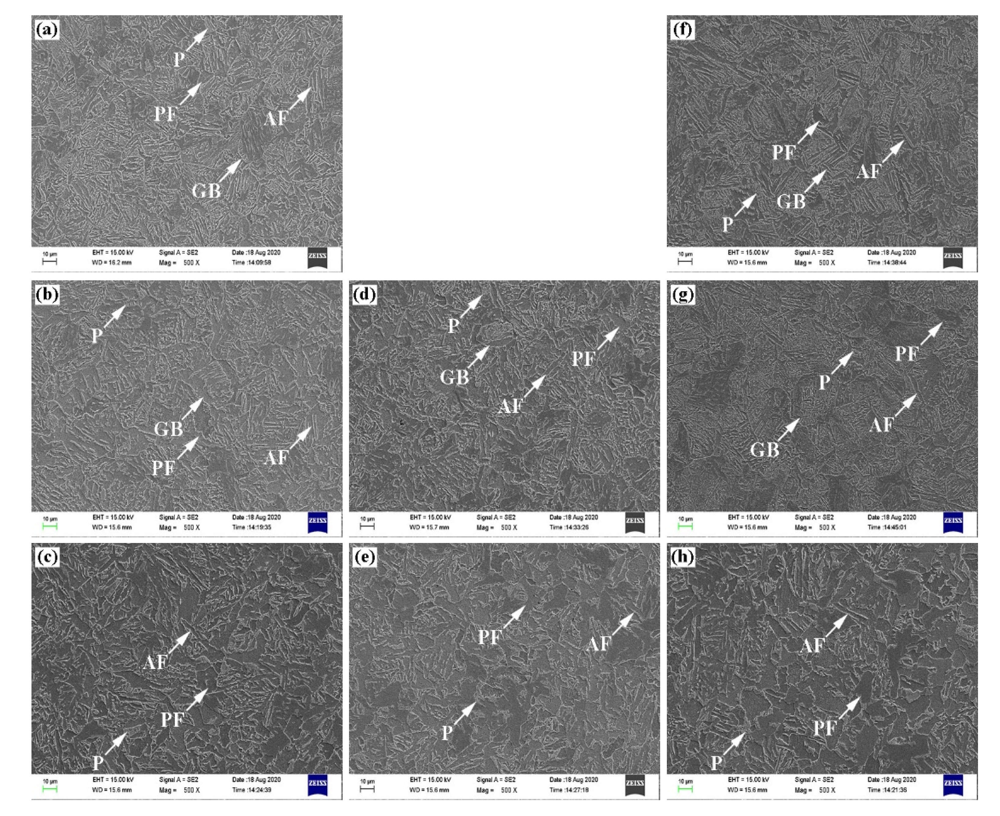
3.2. Microstructural Evolution Analysis

As it can be seen in Figure 4 and Figure 5, after quenching, a small amount of acicular ferrite (AF) and pearlite (P) and a large number of polygonal ferrite (PF) and granular bainite (GB) microstructures appeared on the surface and the 1/4-thickness of the steel plate. This can be attributed to that with the increase of cooling speed, only partial ferrite transformation occurred during the cooling process. In addition, since they were cooled to a lower temperature range, the ferrite and pearlite transformations were inhibited, while the amount of bainite microstructure at medium and low temperatures increased gradually [12,13]. The microstructure at the 1/2-thickness, where the cooling rate was slower, consisted mostly of polygonal ferrite and pearlite. Due to the different cooling rates, the grain size increased gradually along the thickness direction of the plate. The average grain size at the upper surface of the steel plate was 9.1 μm at the head and 9.4 μm at the tail; at the 1/4-thickness position of the steel plate, it was 15.7 μm at the head, 17.6 μm at the middle, and 16.3 μm at the tail; at the 1/2-thickness position of the steel plate, it was 23.4 μm at the head, 22.5 μm at the middle, and 21.6 μm at the tail. The average grain size increased gradually along the thickness direction of the plate, while it was relatively uniform with little changes along the length direction of the plate. When the cooling rate is high, the driving force of nucleation increases, increasing the ferrite phase transformation and refining the polygonal ferrite. When the cooling rate is low, the cooling time becomes longer, and the carbon atoms have more sufficient time to redistribute at the ferrite/austenite interface. Therefore, the austenite carbon content at the interface will increase, inhibiting the growth of ferrite lath to a certain extent, which leads to the formation of ferrite with larger grain size and higher content, while its shape is mainly polygonal [14,15].

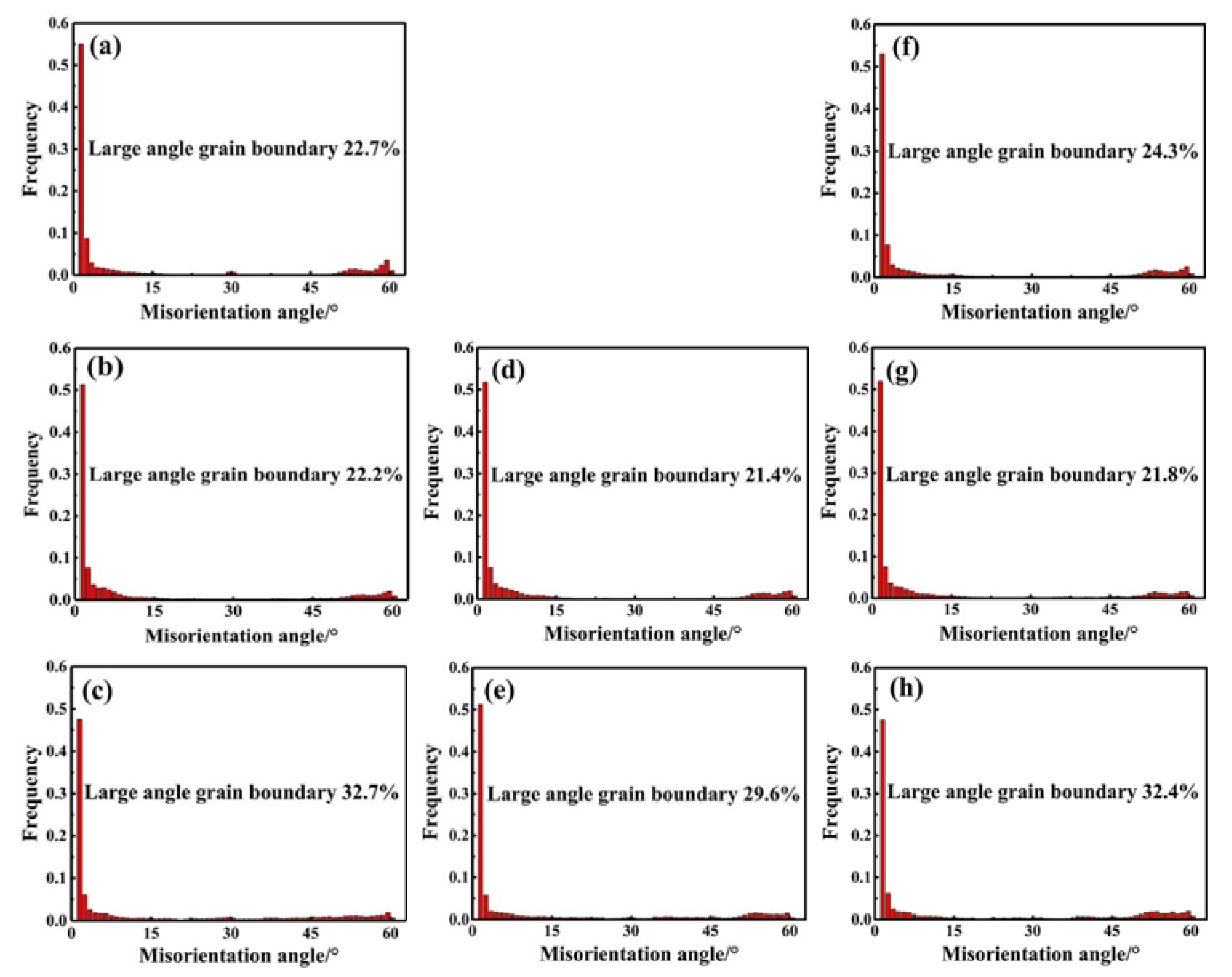
3.3. EBSD Analysis of Microstructural Evolution

Figure 6 shows the crystallographic characteristics of the tested steel specimens analyzed by EBSD. Blue lines represent low-angle boundaries (2–15°), and the red lines correspond to high-angle boundaries (>15°) [16]. The grain boundaries between laths in bainite were mainly low-angle grain boundaries, most of which were observed at the 1/4-thickness position of the steel plate. The grain boundaries between polygonal ferrites were principally high-angle grain boundaries [17,18], most of which were observed at the 1/2-thickness position of the steel plate.
As it can be seen in Figure 7, the proportion of high-angle grain boundaries at the upper surface of the steel plate was 24.3% at the head and 22.7% at the tail; at the 1/4-thickness position of the steel plate, it was 21.8% at the head, 21.4% at the middle, and 22.7% at the tail; at the 1/2-thickness position of the steel plate, it was 32.4% at the head, 29.6% at the middle, and 32.7% at the tail. The proportion of high-angle grain boundaries increased gradually along the thickness direction of the plate, while it was relatively uniform with little changes along the length direction of the plate.

3.4. TEM Analysis of Microstructural Evolution

As it can be observed in Figure 8, the pearlite interlamellar spacing at the upper surface of the steel plate was 0.09 μm at the head and 0.08 μm at the tail; at the 1/4-thickness position of the steel plate, it was 0.11 μm at the head, 0.13 μm at the middle, and 0.15 μm at the tail; at the 1/2-thickness position of the steel plate, it was 0.14 μm at the head, 0.17 μm at the middle, and 0.19 μm at the tail. The pearlite interlamellar spacing increased gradually along the thickness direction of the plate, while it was relatively uniform with little changes along the length direction of the plate. According to Figure 3, the cooling rate decreased gradually along the thickness direction of the plate, which was inversely proportional to the behavior of the pearlite interlamellar spacing. The higher the cooling rate, the finer the pearlite interlamellar spacing. This is attributed to that when the cooling rate increased, the carbon concentration in austenite increased. At the same time, due to the decrease in temperature, the activity of the atoms was weakened and the diffusion distance was shortened, leading to a decrease in pearlite interlamellar spacing [19,20,21,22].

3.5. Mechanical Properties

It can be seen in Figure 9a that the yield strength, tensile strength, and elongation of the upper surface of the steel plate were, respectively, 489.5 MPa, 652.8 MPa, and 14.3% at the head and 471.1 MPa, 643.1 MPa, and 15.3% at the tail; at the 1/4-thickness position of the steel plate, they were, respectively, 435.8 MPa, 597.9 MPa, and 15.8% at the head, 415.3 MPa, 583.7 MPa, and 16.1% at the middle, and 400.4 MPa, 561.1 MPa, and 16.5% at the tail; at the 1/2-thickness position of the steel plate, they were, respectively, 386.4 MPa, 593.2 MPa, and 16.6% at the head, 380.6 MPa, 586.2 MPa, and 16.9% at the middle, and 372.4 MPa, 580.2 MPa, and 17.2% at the tail. It can be observed that the yield strength and tensile strength decreased, while the elongation increased gradually along the thickness direction of the plate; however, all properties were relatively uniform with little changes along the length direction of the plate. According to Figure 3 and Figure 4, the surface strength (P1 and P6) of the steel plate was higher because of the faster cooling rate and more bainite content. Along the thickness direction of the steel plate, the cooling rate and bainite content gradually decreased, so the strength gradually decreased. It can be seen in Figure 8 that the pearlite interlamellar spacing increased gradually along the thickness direction of the plate, which was opposite to the change trend of the strength. The strength of pearlite is governed by interlamellar spacing. A decrease in interlamellar spacing contributes to a higher strength.
As it can be seen in Figure 9b, the hardness and impact energy of the upper surface of the steel plate were, respectively, 240.4 HV and 162.9 J at the head and 237.7 HV and 160.8 J at the tail; at the 1/4-thickness position of the steel plate, they were, respectively, 213.2 HV and 153.5 J at the head, 217.5 HV and 153.1 J at the middle, and 210.3 HV and 154.2 J at the tail; at the 1/2-thickness position of the steel plate, they were, respectively, 183.5 HV and 146.7 J at the head, 185.1 HV and 144.6 J at the middle, and 174.7 HV and 142.3 J at the tail. While the hardness and impact energy of the steel plate decreased gradually along the thickness direction, they were relatively uniform with little changes along the length direction. According to Figure 3 and Figure 4, as the cooling rate decreased, the content of polygonal ferrite increased gradually, while the hardness decreased gradually. The low-temperature impact toughness is not only related to the proportion of the high-angle grain boundary, but also to grain size. It can be seen in Figure 6 and Figure 7 that, despite that the relative proportion of the high-angle grain boundaries at 1/2-thickness was large, the grains were relatively large and the impact absorption energy was relatively low. Consequently, in order to improve the low-temperature impact toughness of the experimental steel, it is necessary not only to increase the proportion of high-angle grain boundaries in the microstructure, but also to refine the grain size as much as possible.
As shown in Figure 10, the proportion of fiber zone and shear lip zone in the fracture surface decreased gradually along the thickness direction of the plate, but they were relatively uniform with little changes along the length direction of the plate. The larger the proportion of fiber zone and shear lip zone, the better toughness of the material. The toughness of the steel plate decreased gradually along the thickness direction, while it was relatively uniform with little changes along the length direction. This was similar to the change trend of impact energy, as shown in Figure 8b.
As shown in Figure 11, the amount of large dimples and their depth decreased gradually along the thickness direction of the plate, which was similar to the change trend of the impact energy in Figure 9b. The amount and depth of dimples was relatively uniform with little changes along the length direction of the plate. According to Figure 4, the more uniform the microstructure, the finer the grain size, the greater the resistance to crack formation and propagation, and the better the impact properties [23,24,25].

4. Conclusions

The effects of roller quenching on the relationships and corresponding interaction mechanisms between cooling rate, temperature gradient, microstructure, and mechanical properties of a 300 mm thickness ultra-heavy steel plate were investigated. The principal conclusions can be drawn as follows:
(1)
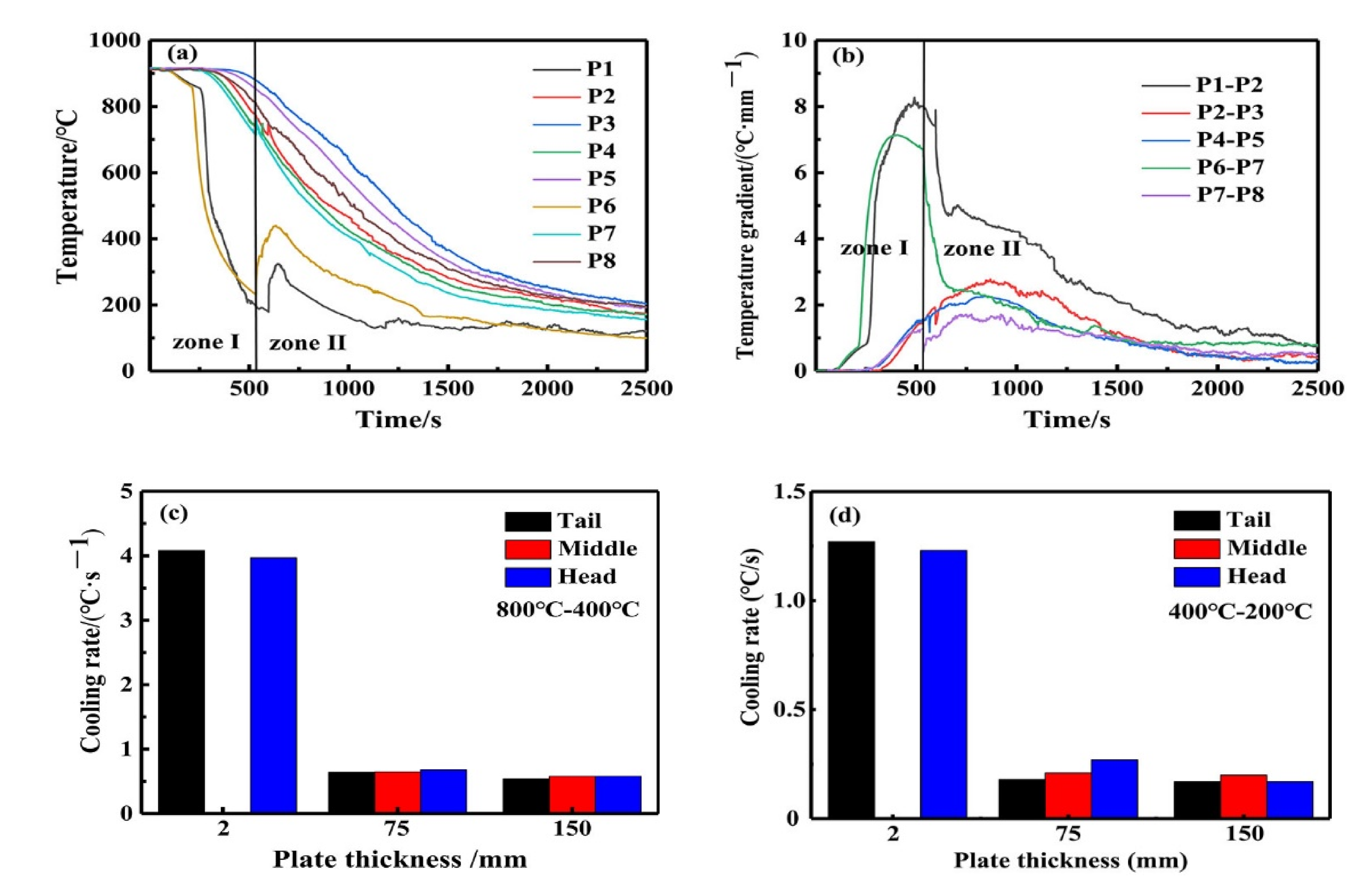
The cooling rate on the upper surface of the steel plate was 3.96 °Cs−1 at the head and 4.08 °Cs−1 the tail; at the 1/4-thickness position of the steel plate, it was 0.68 °Cs−1 at the head, 0.65 °Cs−1 at the middle, and 0.64 °Cs−1 at the tail; at the 1/2-thickness position of the steel plate, it was 0.58 °Cs−1 at the head, 0.58 °Cs−1 at the middle, and 0.54 °Cs−1 at the tail. The cooling rate decreased gradually along the thickness direction of the plate, while it was relatively uniform with little changes along the length direction of the plate.
(2)
The average grain size at the upper surface of the steel plate was 9.1 μm at the head and 9.4 μm at the tail; at the 1/4-thickness position of the steel plate, it was 15.7 μm at the head, 17.6 μm at the middle, and 16.3 μm at the tail; at the 1/2-thickness position of the steel plate, it was 23.4 μm at the head, 22.5 μm at the middle, and 21.6 μm at the tail. The average grain size increased gradually along the thickness direction of the plate, while it was relatively uniform with little changes along the length direction of the plate.
(3)
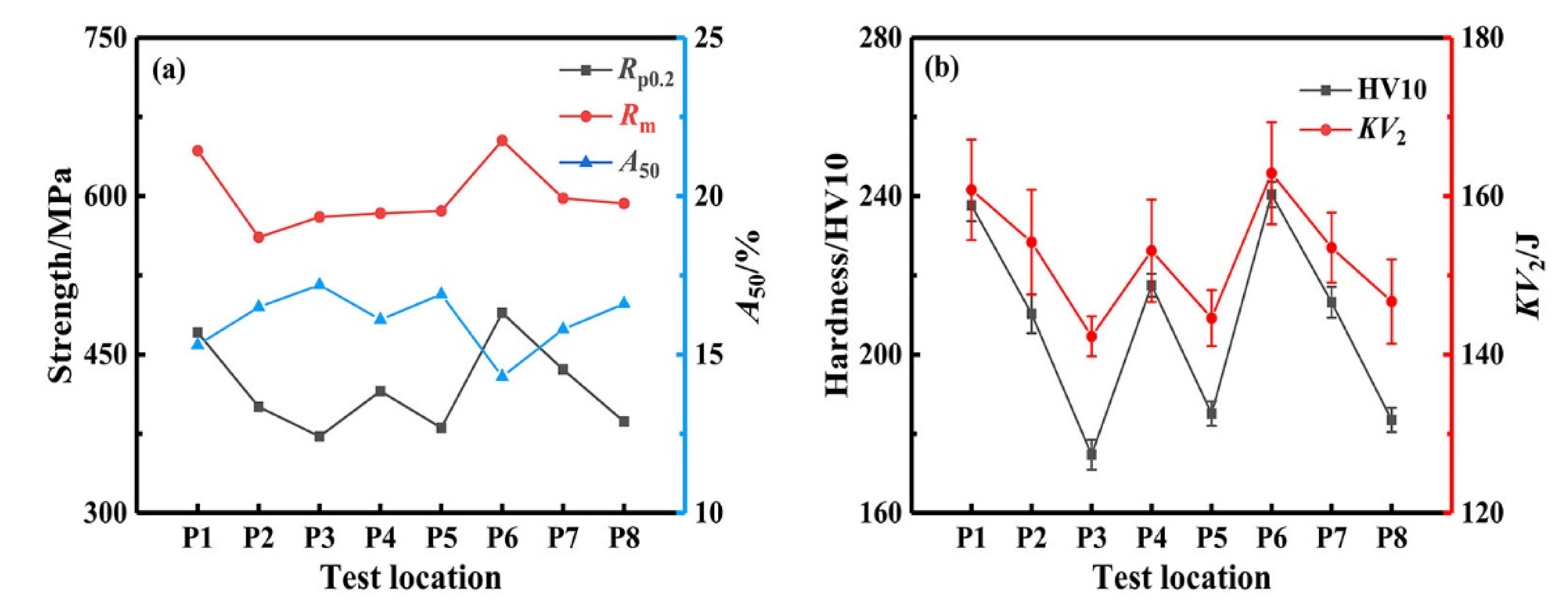
The strength, hardness, and impact energy decreased gradually along the thickness direction of the plate, while the elongation increased. The properties were relatively uniform with little changes along the length direction of the plate.
(4)
The special roller quenching equipment could provide ultra-heavy steel plate with excellent microstructure and properties along the length direction, which were relatively uniform. The next step is to optimize the quenching process and improve the microstructure and properties along the thickness direction of the ultra-heavy steel plate.
(5)
The temperature recorder moved together with the test steel plate, enabling the measurement of the changes in steel plate temperature during the entire quenching process in real time, following the complex movement of the steel plate that included acceleration, deceleration, and swing. This provides a new method for measuring the cooling rate of ultra-heavy steel plates during roller quenching.

Author Contributions

Conceptualization, J.H. and T.F.; investigation, J.H.; data curation, J.H. and T.F.; writing–original draft preparation, J.H.; writing–review and editing, J.H. and T.F.; funding acquisition, Z.W. and G.W. All authors have read and agreed to the published version of the manuscript.

Funding

The authors gratefully acknowledge support from the National Key Research and Development Program of China [Grant no. 2017YFB0305102].

Conflicts of Interest

The authors declare no conflict of interest.

References

  1. Wang, Z.D.; Wang, B.X.; Wang, B.; Tian, Y.; Zhang, T.; Yuan, G.; Liu, Z.Y.; Wang, G.D. Development and Application of Thermo-mechanical Control Process Involving Ultra-fast Cooling Technology in China. ISIJ Int. 2019, 59, 2131–2141. [Google Scholar] [CrossRef] [Green Version]
  2. Tsuyama, S. Thick Plate Technology for the Last 100 Years: A World Leader in Thermo Mechanical Control Process. ISIJ Int. 2015, 55, 67–78. [Google Scholar] [CrossRef] [Green Version]
  3. Fu, T.L.; Wang, Z.D.; Li, Y.; Li, J.D.; Wang, G.D. The influential factor studies on the cooling rate of roller quenching for ultra heavy plate. Appl. Therm. Eng. 2014, 70, 800–807. [Google Scholar] [CrossRef] [Green Version]
  4. Wang, C.; Wang, Z.D.; Yuan, G.; Wang, J.P.; Wang, G.D. Heat Transfer During Quenching by Plate Roller Quenching Machine. J. Iron Steel Res. Int. 2013, 20, 1–5. [Google Scholar] [CrossRef]
  5. Carlone, P.; Palazzo, G.S.; Pasquino, R. Finite element analysis of the steel quenching process: Temperature field and solid-solid phase change. Comput. Math. Appl. 2010, 59, 585–594. [Google Scholar] [CrossRef] [Green Version]
  6. Woodard, P.R.; Chandrasekar, S.; Yang, H.T.Y. Analysis of Temperature and Microstructure in the Quenching of Steel Cylinders. Metal. Mater. Trans. B 1999, 30, 815–822. [Google Scholar] [CrossRef]
  7. Yang, X.W.; Zhu, J.C.; Nong, Z.S.; Lai, Z.H.; He, D. FEM Simulation of Quenching Process in A357 Aluminum alloy cylindrical bars and reduction of quench residual stress through cold stretching process. Comput. Mater. Sci. 2013, 69, 396–413. [Google Scholar] [CrossRef]
  8. Li, H.P.; Zhao, G.Q.; Niu, S.T.; Huang, C.Z. FEM simulation of quenching process and experimental verification of simulation results. Mater. Sci. Eng. A 2007, 452, 705–714. [Google Scholar]
  9. Kang, S.H.; Im, Y.T. Three-dimensional thermo-elasticplastic finite element modeling of quenching process of plain-carbon steel in couple with phase transformation. Int. J. Mech. Sci. 2007, 49, 423–439. [Google Scholar] [CrossRef]
  10. Şimşir, C.; Gür, C.H. 3D FEM simulation of steel quenching and investigation of the effect of asymmetric geometry on residual stress distribution. J. Mater. Process. Technol. 2008, 207, 211–221. [Google Scholar] [CrossRef]
  11. Fu, T.L.; Wang, Z.D.; Deng, X.T.; Liu, G.H.; Wang, G.D. Latent heat model of a medium plate in case of jet quenching. Appl. Therm. Eng. 2016, 100, 1327–1333. [Google Scholar] [CrossRef]
  12. Qu, S.P.; Zhang, Y.C.; Pang, X.L.; Gao, K.W. Influence of temperature field on the microstructure of low carbon microalloyed ferrite-bainite dual-phase steel during heat treatment. Mater. Sci. Eng. A 2012, 536, 136–142. [Google Scholar] [CrossRef]
  13. Wu, J.Y.; Wang, B.; Wang, B.X.; Misra, R.D.K.; Wang, Z.D. Toughness and ductility improvement of heavy EH47 plate with grain refinement through inter-pass cooling. Mater. Sci. Eng. A 2018, 733, 117–127. [Google Scholar] [CrossRef]
  14. Sabet Ghorabaei, A.; Ghasemi Banadkouki, S.S. Abnormal mechanical behavior of a medium-carbon steel under strong ferrite-pearlite-martensite triple-phase microstructures. Mater. Sci. Eng. A 2017, 700, 562–573. [Google Scholar] [CrossRef]
  15. Mohamadizadeh, A.; Zarei-Hanzaki, A.; Heshmati-Manesh, S.; Imandoust, A. The effect of strain induced ferrite transformation on the microstructural evolutions and mechanical properties of a TRIP-assisted steel. Mater. Sci. Eng. A 2014, 607, 621–629. [Google Scholar] [CrossRef]
  16. Mohtadi-Bonab, M.A.; Eskandari, M.; Szpunar, J.A. Role of cold rolled followed by annealing on improvement of hydrogen induced cracking resistance in pipeline steel. Eng. Fail. Anal. 2018, 91, 172–181. [Google Scholar] [CrossRef]
  17. Li, S.C.; Guo, C.Y.; Hao, L.L.; Kang, Y.L.; An, Y.G. In-situ EBSD study of deformation behaviour of 600 MPa grade dual phase steel during uniaxial tensile tests. Mater. Sci. Eng. A 2019, 759, 624–632. [Google Scholar] [CrossRef]
  18. Liu, Z.; Song, B.; Yang, Z.B.; Cui, X.K.; Li, L.F.; Wang, L.; Song, Z.R. Effect of Cerium Content on the Evolution of Inclusions and Formation of Acicular Ferrite in Ti-Mg-Killed EH36 Steel. Metals 2020, 10, 863. [Google Scholar] [CrossRef]
  19. Xu, P.W.; Liang, Y.; Li, J.; Meng, C. Further improvement in ductility induced by the refined hierarchical structures of pearlite. Mater. Sci. Eng. A 2019, 745, 176–184. [Google Scholar] [CrossRef]
  20. Dey, I.; Chandra, S.; Saha, R.; Ghosh, S.K. Effect of Nb micro-alloying on microstructure and properties of thermo-mechanically processed high carbon pearlitic steel. Mater. Charact. 2018, 140, 45–54. [Google Scholar] [CrossRef]
  21. Zhao, Y.G.; Tan, Y.B.; Ji, X.M.; Xiang, Z.J.; He, Y.; Xiang, S. In situ study of cementite deformation and its fracture mechanism in pearlitic steels. Mater. Sci. Eng. A 2018, 731, 93–101. [Google Scholar] [CrossRef]
  22. Zhang, Z.H.; Liu, Y.; Zhou, Y.N.; Dong, C.X.; Zhang, C.X.; Cao, G.H.; Schneider, R.; Gerthsen, D. Effect of precipitation of (Ti,V)N and V(C,N) secondary phases on mechanical properties of V and N microalloyed 1Cr steels. Mater. Sci. Eng. A 2018, 738, 203–212. [Google Scholar] [CrossRef]
  23. Yang, J.; Huang, F.; Guo, Z.H.; Rong, Y.H.; Chen, N.L. Effect of retained austenite on the hydrogen embrittlement of a medium carbon quenching and partitioning steel with refined microstructure. Mater. Sci. Eng. A 2016, 665, 76–85. [Google Scholar] [CrossRef]
  24. Hu, J.; Du, L.X.; Xie, H.; Gao, X.H.; Misra, R.D.K. Structure-mechanical property relationship in low carbon microalloyed steel plate processed using controlled rolling and two-stage continuous cooling. Mater. Sci. Eng. A 2013, 585, 422–429. [Google Scholar] [CrossRef]
  25. Cao, R.; Li, G.; Fang, X.Y.; Song, J.; Chen, J.H. Investigation on the effects of microstructure on the impact and fracture toughness of a C-Mn steel with various microstructures. Mater. Sci. Eng. A 2013, 564, 509–524. [Google Scholar] [CrossRef]
Figure 1. Schematic illustration of the 300 mm steel plate indicating the locations of the temperature measurement points.
Metals 10 01238 g001
Figure 2. Images of experimental equipment and steel-plate quenching process: (a) before quenching, (b) quenching, and (c) after quenching.
Metals 10 01238 g002
Figure 3. Cooling curves during quenching: (a) temperature versus time at the different measurement points; (b) temperature gradient along the plate thickness; (c) high temperature range cooling rate; (d) low-temperature range cooling rate.
Metals 10 01238 g003
Figure 4. Steel-plate microstructure at the different temperature measurement points. Images (ah) demonstrate the microstructure at points P1–P8, respectively.
Metals 10 01238 g004
Figure 5. SEM microstructure of steel plate at the different temperature measurement points. Images (ah) demonstrate the microstructure at points P1–P8, respectively.
Metals 10 01238 g005
Figure 6. EBSD image quality maps with grain boundary misorientation distribution at the different temperature measurement points. Images (ah) show the results for points P1–P8, respectively.
Metals 10 01238 g006
Figure 7. Grain-boundary misorientation angle distribution at the different temperature measurement points. Images (ah) show the results for points P1–P8, respectively.
Metals 10 01238 g007
Figure 8. TEM micrographs at the different temperature measurement points. Images (ah) show the results for points P1–P8, respectively.
Metals 10 01238 g008
Figure 9. Mechanical properties at the different temperature measurement points. (a) Strength and elongation, (b) hardness and impact energy.
Metals 10 01238 g009
Figure 10. Impact fractographs at the different temperature measurement points. Images (ah) exhibit the results for points P1–P8, respectively.
Metals 10 01238 g010
Figure 11. Impact fractographs of the fibrous zone at the different temperature measurement points. Images (ah) exhibit the results for points P1-P8, respectively.
Metals 10 01238 g011

