Article

Corrosion Behavior of As-Cast Ti–10Mo–6Zr–4Sn–3Nb and Ti–6Al–4V in Hank’s Solution: A Comparison Investigation

1
State Key Laboratory of Solidification Processing, Northwestern Polytechnical University, Xi’an 710072, China
2
Northwest Institute for Nonferrous Metal Research, Shaanxi Key Laboratory of Biomedical Metal Materials, Xi’an 710016, China
3
School of Materials Science and Engineering, Inner Mongolia University of Technology, Hohhot 010051, China
4
School of Materials Science and Engineering, Shenyang University of Technology, Shenyang 110870, China
5
School of Material Science and Engineering, China University of Mining and Technology, Xuzhou 221008, China
6
State Key Laboratory of Powder Metallurgy, Central South University, Changsha 410083, China
*
Author to whom correspondence should be addressed.
Metals 2021, 11(1), 11; https://doi.org/10.3390/met11010011
Submission received: 29 November 2020 / Revised: 13 December 2020 / Accepted: 17 December 2020 / Published: 23 December 2020

Abstract

:
Newly developed Ti–10Mo–6Zr–4Sn–3Nb has fascinating mechanical properties to be used as a biomedical material. However, there is still a lack of investigation focusing on the corrosion behavior of Ti–10Mo–6Zr–4Sn–3Nb. In this work, the microstructure and corrosion behavior of as-cast Ti–10Mo–6Zr–4Sn–3Nb was investigated by optical microscopy, X-ray diffraction, and electrochemical measurements. Hank’s solution was used as the electrolyte. A classical as-cast Ti–6Al–4V was used as reference. The results showed that Ti–10Mo–6Zr–4Sn–3Nb has a higher corrosion potential and a lower corrosion current density compared with Ti–6Al–4V, indicating better corrosion resistance. However, after applying anodic potentials, Ti–10Mo–6Zr–4Sn–3Nb shows larger passivation current density in both potentiodynamic polarization and potentiostatic polarization tests. This is because more alloying elements contained in Ti–10Mo–6Zr–4Sn–3Nb trigger the production of a larger number of oxygen vacancies, resulting in a higher flux of oxygen vacancy. This finding illustrates that the passive film on Ti–10Mo–6Zr–4Sn–3Nb is less protective compared with that on Ti–6Al–4V when applying an anodic potential in their passivation range.

Graphical Abstract

1. Introduction

Titanium (Ti) and Ti alloys have been used as biomedical materials for many years, owing to their high mechanical properties, high corrosion resistance, and excellent biocompatibility [1,2,3,4,5,6]. Since the 1950s, commercial pure Ti (CP–Ti) has been used as implant material, which is mainly composed of the α-phase [2]. CP–Ti has moderate strength, which may not satisfy the requirement of some hard tissues or load-bearing connective tissues [7]. Hence, (α + β)-type Ti alloys, which have higher strength, were gradually developed, such as Ti–6Al–4V, Ti–6Al–7Nb, and Ti–5Al–2.5Fe [8,9,10,11,12]. Such (α + β)-type Ti alloys exhibit high strength, high fatigue resistance, and good corrosion resistance. Therefore, they have been used as implant materials for a long period. However, there are still some questions about (α + β)-type Ti alloys used as implants. On the one hand, the moduli of (α + β)-type Ti alloys are significantly higher than those of human bones. Hence, the stress-shielding effect, which results from the difference in the moduli of implant and bone counterpart, may be caused during the service of implants [13,14]. On the other hand, (α + β)-type Ti alloys contain detrimental elements, such as Al and V, which are the potential hazard for the human body [15]. As such, β-type Ti alloys with low moduli and nontoxic elements were developed in the last three decades, including Ti–13Nb–13Zr [16], Ti–24Nb–4Zr–8Sn [17,18,19,20], Ti–35Nb–2Ta–3Zr [21,22], Ti–35Nb–5Ta–7Zr [23], etc.
A novel metastable β-type Ti alloy, namely, Ti–10Mo–6Zr–4Sn–3Nb, has been developed by the Northwest Institute for Non-Ferrous Metal Research in China, which has desirable mechanical properties and can potentially be used as a biomedical material [24,25,26]. The solution-treated Ti–10Mo–6Zr–4Sn–3Nb has a low elastic modulus of 65 GPa, and monolithically consists of the β-phase [26]. Du et al. [26] investigated the microstructures and mechanical properties of Ti–10Mo–6Zr–4Sn–3Nb after aging at 400–550 °C. The results showed that α- and ω-phases are produced after aging at various temperatures. Hence, the microstructure of Ti–10Mo–6Zr–4Sn–3Nb changes from monolithic β-phase to hybrid α + ω + β phases [26]. Correspondingly, the ultimate tensile strength of Ti–10Mo–6Zr–4Sn–3Nb increases from 878 MPa to 1250 MPa, and its elongation decreases from 32% to almost zero depending on the aging temperature and time. Cheng et al. [24] conducted the cold swaging deformation with reductions of 15–75% on solution-treated Ti–10Mo–6Zr–4Sn–3Nb and pointed out that stress-induced martensite transformation takes place during deformation. As a result, the strength of the alloy increases with the increment in the cold deformation reduction [24]. After the reduction of 75%, the strength of Ti–10Mo–6Zr–4Sn–3Nb reaches 1324 MPa, while its modulus is only 70 GPa [24]. Therefore, in comparison to other β-type Ti alloys, it can be concluded that Ti–10Mo–6Zr–4Sn–3Nb is a significant potential for biomedical applications.
For biomedical materials, their corrosion behavior is also critical for consideration besides the mechanical properties, because the human body is an aqueous environment. Ti and Ti alloys are inevitably corroded in such an environment. Ti and Ti alloys are passive metals. During corrosion, protective passive films would be formed on passive metals against the ingression of the corrosive medium [19,27,28,29,30]. If the passive film is ruptured, it can be re-formed rapidly [31]. Therefore, a considerable endeavor was made to investigate the corrosion behavior of Ti and Ti alloys and the characteristics of the formed passive films. For instance, Wang et al. [31] compared electrochemical characterization of CP–Ti, Ti–6Al–4V, Ti–29Nb–13Ta–4.5Zr, Ti–35Nb–15Zr, and Ti–25Nb–8Zr prepared by various methods. The results illustrate that Ti–29Nb–13Ta–4.5Zr shows the lowest corrosion potential of −706 ± 13 mVSCE and selective laser-melted Ti–6Al–4V has the highest corrosion current of 0.65 ± 0.07 μA·cm−2. Gai et al. [32] investigated the electrochemical behavior of wrought and electron beam-melted Ti–6Al–4V in phosphate-buffered saline, and found that the passive film formed on electron beam-melted Ti–6Al–4V has a slower growth rate compared with that formed on the wrought counterpart. Atapour et al. [33] specified that metastable β-type Ti–13Mo–7Zr–3Fe has a lower corrosion current density and a lower passivation current density than Ti–6Al–4V in Ringer’s solution. Based on the above results, it can be understood that the corrosion resistance of Ti alloys may be varied with the change in the alloy compositions and phase constituents. Therefore, to better understand the corrosion behavior of a specific Ti alloy, the investigation for the electrochemical behavior of the alloy in the simulated physiological fluid is required. For a newly designed alloy, although there are adequate investigations of mechanical properties of this alloy, the electrochemical behavior of Ti–10Mo–6Zr–4Sn–3Nb is still unknown in a simulated physiological fluid.
In this work, an as-cast Ti–10Mo–6Zr–4Sn–3Nb was selected as an experimental alloy and its electrochemical behavior, as well as the characteristics of the formed passive film, was investigated. Hank’s solution was selected as the electrolyte. As-cast Ti–6Al–4V was used as a reference. To clarify the focus question, optical microscopy, X-ray diffraction, potentiodynamic polarization tests, potentiostatic polarization tests, and Mott–Schottky measurements were used. The corrosion mechanism of Ti–10Mo–6Zr–4Sn–3Nb is discussed.

2. Experimental

2.1. Material Preparation

The Ti and Zr sponges, and Ti–32Mo, Ti–60Sn, and Nb–47Ti master alloys were selected as raw materials to prepare Ti–10Mo–6Zr–4Sn–3Nb. The obtained ingot was prepared via vacuum arc remelting (VAR) three times to ensure its uniformity. A Ti–6Al–4V alloy prepared by the same method was used as a reference. The compositions of both alloys are shown in Table 1.

2.2. Microstructural Characterizations

The alloy sample was ground and polished by standard metallographic technique to a mirror surface finish. Afterward, the polished specimens were etched in Keller’s solution (10 vol% HF, 20 vol% HNO3, and 70 vol% H2O) for about 20 s. An optical microscope (OM, OLYMPUS PMG3) was used to characterize the microstructure of the etched alloy sample. An X-ray diffraction (XRD) diffractometer (Empyrean, PANalytical, Eindhoven, Netherlands) with Co-Kα radiation was used to analyze the phase constituents of polished samples. The scanning range was between 30° and 100°, and the scanning rate was 0.03°/s. Jade 6.5 software (Materials Data, Inc., Santa Clara, CA, USA) was used to process the XRD data.

2.3. Electrochemical Measurements

The samples with the dimensions of 10 mm × 10 mm × 10 mm were used for electrochemical measurements. Hence, the exposure areas of samples in electrochemical measurements were about 1.0 cm2. Hank’s solution was used as the electrolyte. The composition of Hank’s solution is 0.140 g·L−1 CaCl2, 0.098 g·L−1 MgSO4, 0.4 g·L−1 KCl, 0.06 g·L−1 KH2PO4, 8 g·L−1 NaCl, 0.35 g·L−1 NaHCO3, 0.048 g·L−1 Na2HPO4, 1 g·L−1 C6H12O6, and 0.011 g·L−1 C19H14O5SNa. Hank’s solution was kept at 37 ± 0.5 °C for electrochemical measurements. An electrochemical workstation with a three-electrode system (CHI660E, Chenhua) was used to characterize the electrochemical behavior of samples. Alloy sample was used as the working electrode, a platinum sheet was used as the counter electrode and a saturated calomel electrode (SCE) was used as the reference electrode. To ensure the stability of samples in Hank’s solution, an 1800 s open circuit potential (OCP) was conducted. Afterwards, electrochemical impedance spectroscopy (EIS) was conducted at peak-to-peak sinusoidal voltage signals of 10 mV in the frequency range between 10−2 Hz and 105 Hz. The software ZsimpWin 3.30 (Princeton Applied Research, Princeton, NJ, USA) was used to process the EIS data. Subsequently, potentiodynamic polarization tests were conducted in a sweeping range of from −0.25 to2 V (vs. OCP) at a sweeping step of 0.2 mV/s. The software Cview 2.6 (Scribner Associates Inc., Southern Pines, NC, USA) was used to process the potentiodynamic polarization data. The potentiostatic polarization was employed to passivate the alloy samples at the potentials of 0.6 V, 0.7 V, 0.8 V, 0.9 V, and 1.0 V. Subsequently, electrochemical impedance spectroscopy was carried out to obtain the effective capacitance at 1 kHz [34]. Afterward, Mott–Schottky tests were conducted at the frequency of 1 kHz, sweeping the potential from film formation potential to −1.0 V (vs. OCP) with a step of 10 mV/s. All the potentials reported in this work were against SCE. Each electrochemical test was repeated three times to ensure data reproducibility.

3. Results

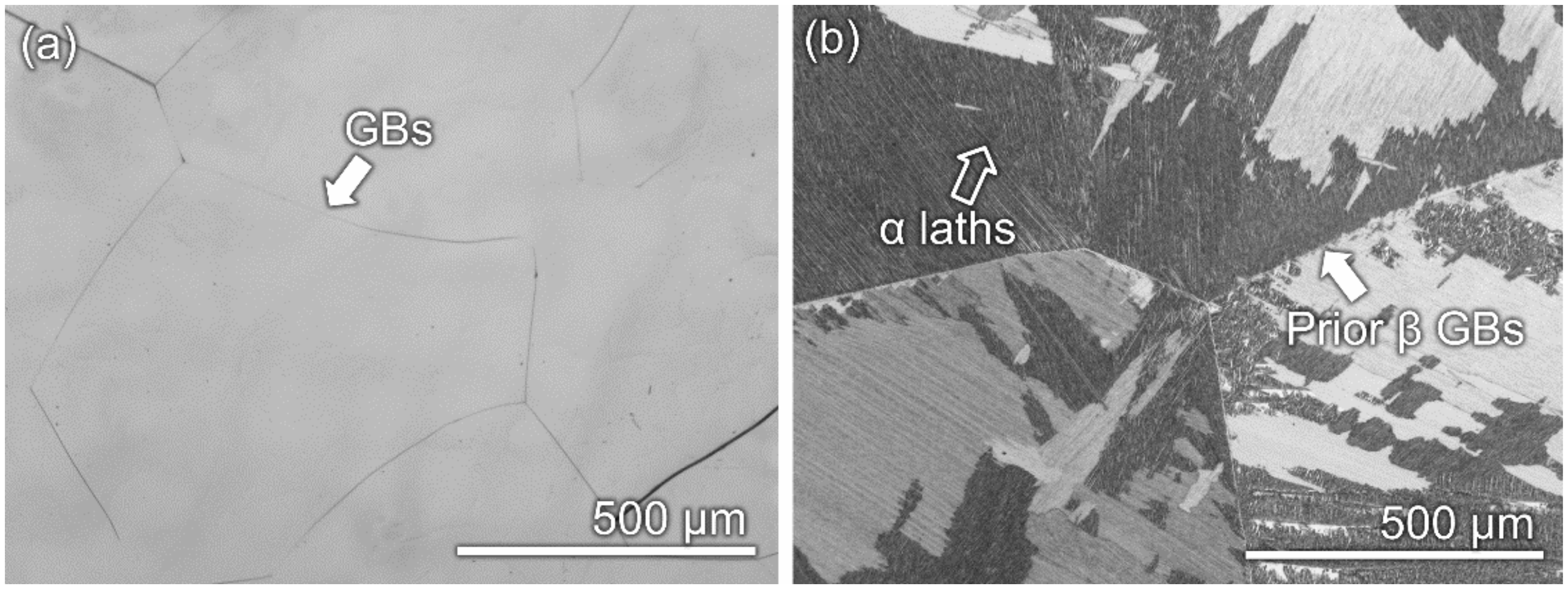
3.1. Microstructural Features

Figure 1 shows the XRD results of Ti–10Mo–6Zr–4Sn–3Nb and Ti–6Al–4V samples used in this work. Apparently, only β-phase is detected in Ti–10Mo–6Zr–4Sn–3Nb, indicating a monolithic β phase in the microstructure. In comparison, both α- and β-phases are found in the XRD pattern of Ti–6Al–4V, which is consistent with the results in the literature [35]. According to the method of integrated areas of peaks in the XRD pattern [36,37], Ti–6Al–4V has about 5 vol.% β-phase and 95 vol.% α-phase. Figure 2 shows the OM microstructures of etched Ti–10Mo–6Zr–4Sn–3Nb and Ti–6Al–4V samples. Ti–10Mo–6Zr–4Sn–3Nb presents multiple polygonal grains with clear boundaries and no other phases are observed (Figure 2a). This finding is in line with the XRD outcome. Although prior β grain boundaries were also observed in the microstructure of Ti–6Al–4V, a considerable number of α laths were found in the grains (Figure 2b). These laths were produced during the transformation of β to α, which is frequently observed in hexagonal close-packed metals [9,38,39,40,41]. The microstructures of both alloys are typically found in β-type Ti alloys and (α + β)-type Ti alloys [3,19,42].

3.2. Open Circuit Potential

Figure 3 shows the open circuit potentials (OCPs) for Ti–10Mo–6Zr–4Sn–3Nb and Ti–6Al–4V in Hank’s solution at 37 °C. Similar trends, namely, a positive shift of potentials, are found for both samples, indicating the spontaneous formation of passive films formed Ti–10Mo–6Zr–4Sn–3Nb and Ti–6Al–4V. Such phenomena are found in many passive metals (such as Ti, Zr, steel, and Ni); the metals are active in corrosive environments. However, protective films can be quickly formed on the metals against the aggressive species [27,43,44,45,46]. After immersion in Hank’s solution for 400 s, OCPs are gradually stabilized. After 1800 s immersion, Ti–10Mo–6Zr–4Sn–3Nb displayed a higher OCP (−0.3869 VSCE) than Ti–6Al–4V (−0.4923 VSCE). OCP test is a balance between the formation and dissolution of passive films formed on the samples within the test period. Therefore, Ti–10Mo–6Zr–4Sn–3Nb with a higher OCP demonstrates a better corrosion resistance under self-corrosion conditions.

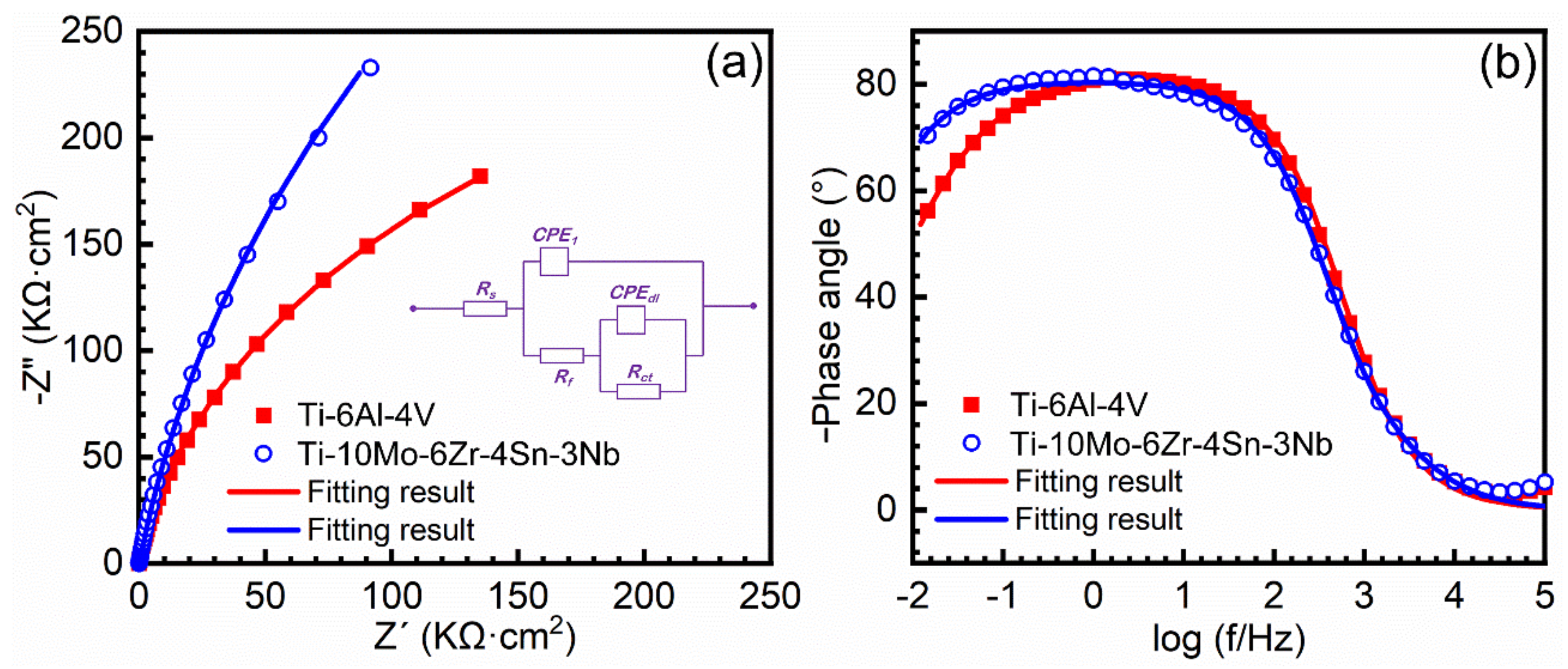
3.3. Potentiodynamic Polarization Test and Electrochemical Impedance Spectroscopy

Typical potentiodynamic polarization curves of Ti–10Mo–6Zr–4Sn–3Nb and Ti–6Al–4V are presented in Figure 4. Both alloys exhibited typical passivation behavior. Even up to 2 VSCE, the passive films formed on both alloys did not breakdown. Table 2 lists the fitting results of potentiodynamic polarization curves. Ti–10Mo–6Zr–4Sn–3Nb showed a slightly higher corrosion potential (−0.430 ± 0.012 VSCE) than Ti–6Al–4V (−0.504 ± 0.044 VSCE), indicating more energy is needed for the corrosion reaction for Ti–10Mo–6Zr–4Sn–3Nb [47]. As seen from Figure 2, as-cast Ti–6Al–4V has a fine lath structure. Indeed, each lath can be considered as a grain with a small size. Such refined grains result in more grain boundaries in the sample. The grain boundaries would increase the surface reactivity of the sample and enhance its dissolution rate in the initial stage of corrosion [48]. Meanwhile, Ti–6Al–4V consists of α- and β-phases, whilst Ti–10Mo–6Zr–4Sn–3Nb has a single-phase structure. A micro-galvanic effect would be produced between different phases, which also accelerates the dissolution of the sample [49]. Such reasons result in a lower corrosion potential of Ti–6Al–4V. Ti–10Mo–6Zr–4Sn–3Nb also has a low corrosion current density (0.007 ± 0.002 μA·cm−2) than Ti–6Al–4V (0.020 ± 0.008 μA·cm−2). Such results illustrate that Ti–10Mo–6Zr–4Sn–3Nb has better corrosion resistance and a slower corrosion rate than Ti–6Al–4V without applied potential [50]. Moreover, the dissolved Ti (Ti ions) resulted from corrosion may form the Ti complex (such as [TiCl6]2−) by combining with the Cl in the solution [49]. If the concentration of [TiCl6]2− reaches a critical value, the passive film would form. Due to the lower corrosion potential and greater corrosion current density, Ti–6Al–4V would have a higher dissolution rate compared with Ti–10Mo–6Zr–4Sn–3Nb. As such, a lower passivation potential of Ti–6Al–4V is observed. With increasing the applied potential, Ti–6Al–4V is first passivated at −0.133 ± 0.012 VSCE, and Ti–10Mo–6Zr–4Sn–3Nb is then passivated at 0.024 ± 0.014 VSCE. The passivation current density of Ti–10Mo–6Zr–4Sn–3Nb (3.664 ± 0.438 μA·cm−2) is slightly higher than that of Ti–6Al–4V (3.111 ± 0.172 μA·cm−2). Up to the potential of 1.1 VSCE, the transpassive domain is observed, which indicates the abrupt increase in current density corresponding to the water decomposition [51]. Such a phenomenon is frequently observed for Ti and Ti alloys [35,51,52]. Transpassivation takes place with the oxygen evolution reaction (decomposition of water) accompanied by the anodic dissolution of metallic ions. With increasing the potential, both alloys are re-passivated. Passivation current density indicates the migration of ions in the passive film. The applied anodic potential can enhance the adsorption of anions in the solution and promote the formation of the passive film. Interestingly, Ti–10Mo–6Zr–4Sn–3Nb has a higher passivation current density than Ti–6Al–4V, indicating a higher ion migration rate of Ti–10Mo–6Zr–4Sn–3Nb after complete passivation. The above results indicate that the passive films formed on Ti–10Mo–6Zr–4Sn–3Nb under different conditions may have different characteristics.
To investigate the characterize the passive films formed on both alloys after the OCP test, EIS measurements were conducted. Figure 5 shows the EIS results of Ti–10Mo–6Zr–4Sn–3Nb and Ti–6Al–4V. Figure 5a is the Nyquist plots for both alloys. The radius of the capacitive loop in the Nyquist plots indicates the impedance of passive film on the alloy surface; the larger the radius of the capacitive loop, the higher the impedance of the passive film [9,43]. Hence, the passive film formed on Ti–10Mo–6Zr–4Sn–3Nb has a slightly higher impedance than Ti–6Al–4V. Figure 5b shows the Bode phase plots for both alloys. Both plots are almost overlapped besides in the range of 0.01~1 Hz. It is well known that the phase angle close to −90° indicates the capitative behavior of a corrosion-resistance material [30,45]. The inset in Figure 5a is the equivalent electrical circuit for fitting the EIS data, where Rs is solution resistance, Rf means film resistance, and Rct indicates charge transfer resistance. It is generally believed that the passive films formed on Ti and Ti alloys have a double-layer structure, namely, the inner barrier layer and outer porous layer [53]. The inner barrier layer shows a high impedance, while the outer porous layer has a significantly low impedance. In this work, Rct can be considered as the impedance of the inner barrier layer, which almost determines the transferring of the charge from the working electrode to the solution. Rf indicates the outer porous layer, which has a significantly low impedance due to its porous feature. CPE is the constant phase element, which is used to describe the non-ideal capacitive behavior of passive film. Table 3 lists the fitted results of EIS data. The value of χ2 is very small (less than 0.001), illustrating the good quality of the fitted results. Rs and Rf are significantly lower than Rct, therefore the value of Rct would determine the corrosion resistance of both alloys. The Rct of Ti–10Mo–6Zr–4Sn–3Nb (1.3297 ± 0.0858 MΩ·cm2) is about two times than that of Ti–6Al–4V (0.7367 ± 0.0082 MΩ·cm2), specifying that the passive film formed on Ti–10Mo–6Zr–4Sn–3Nb has a higher protectiveness in Hank’s solution.

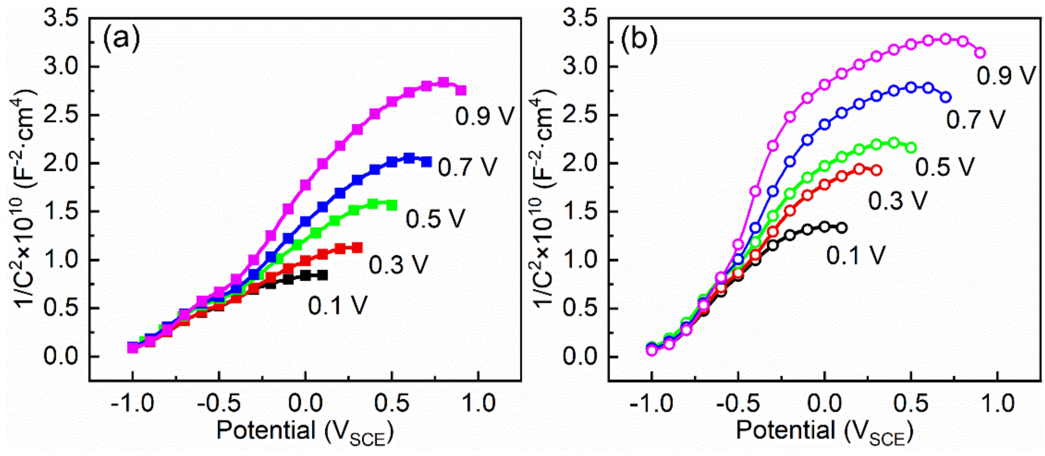
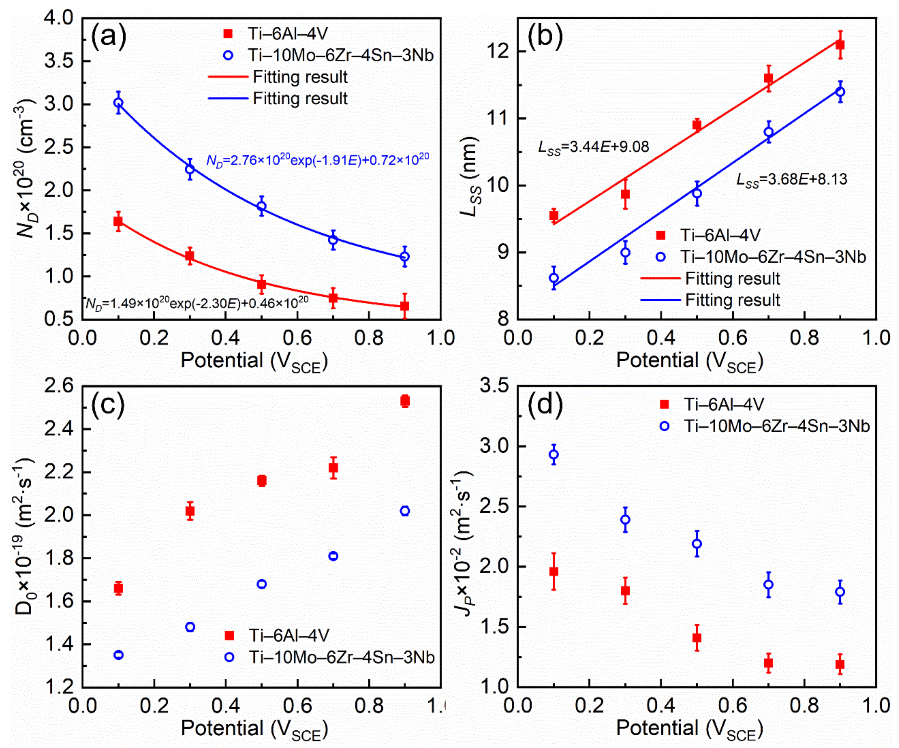
3.4. Mott–Schottky Analysis

Mott–Schottky tests can be used to analyze the semiconductive properties of passive films formed on metals [34]. Before the Mott–Schottky (M–S) test, potentiostatic polarization was employed to passivate the alloy samples. Similar to the results in references [32,34], current density would rapidly decrease to a steady state for passive alloys after several seconds. With increasing the time of potentiostatic polarization, the current density reduces very slowly, which is a result of passivation. As such, the recorded current density is named as quasi-steady-state current density. Figure 6 shows the quasi-steady-state current density for both alloys at various applied potentials after 30 min potentiostatic polarization in Hank’s solution. With increasing the applied potential, the quasi-steady-state current density gradually increases, which is in line with results in the literature [32]. At each selected potential, the quasi-steady-state current density of Ti–10Mo–6Zr–4Sn–3Nb is higher than that of Ti–6Al–4V. This finding is consistent with the results of potentiodynamic polarization, indicating that the passivation current density of Ti–10Mo–6Zr–4Sn–3Nb is higher than that of Ti–6Al–4V.
After the formation of passive films, M–S tests were conducted to examine their semi-conductive properties, which are shown in Figure 7. Figure 7a,b represent the M–S curves of Ti–10Mo–6Zr–4Sn–3Nb and Ti–6Al–4V at different film formation potentials. The typical linear regions of the curves with positive slopes indicate that the passive films on Ti–10Mo–6Zr–4Sn–3Nb and Ti–6Al–4V show typical n-type semiconductive properties. Therefore, the semiconductive properties of the passive film can be conducted as the following equations [54].
C 2 = 2 ε ε 0 e N D E E FB k T e ,
L S S = ε ε 0 A C e f f ,
N D = ω 1 e b E + ω 2 ,
D o = i p R T 4 e F ε L ω 2 ,
L S S = 1 α E ε L + B ,
J P = q i K D o N D ,
where C is the capacitance of passive film; ε is its relative dielectric constant (60 for TiO2 [32]); ε0 is the vacuum dielectric constant (8.85 × 10⁻¹⁴ F·cm−1); e is the electronic charge (1.60 × 10⁻¹⁹ C); ω1, ω2, and b are fitted constants in Equation (2); E is the film formation potential; Lss is the thickness of the passive film; A is the area of the Ti electrode, Ceff is the effective capacitance; Do is the diffusion coefficient of oxygen vacancy; ip is the quasi-steady-state current density (Figure 5); R is the gas constant (8.314 J·mol−1); εL is the electric field intensity in the passive film; α is the polarizability of the passive film/solution interface (α = 0.5 [32]); B is a constant; Jp is the flux determined by potential gradient; qi is the charge of oxygen vacancy (2e); and K is defined as Fε/RT. Based on the above equations, semi-conductive properties of passive films formed on Ti–10Mo–6Zr–4Sn–3Nb and Ti–6Al–4V can be calculated, which are shown in Figure 8.
With increasing the applied potential, the donor densities in both passive films formed on Ti–10Mo–6Zr–4Sn–3Nb and Ti–6Al–4V decrease (Figure 8a). The passive film formed on Ti–10Mo–6Zr–4Sn–3Nb contains more donors at each applied potential. The donors have a significant influence on the ion migration in the passive film [55,56]. According to Equation (2), the thicknesses of passive films are shown in Figure 8b, which have linear relationships with the applied potentials. At the same applied potential, the passive film formed on Ti–6Al–4V has a higher thickness than that formed on Ti–10Mo–6Zr–4Sn–3Nb. Meanwhile, according to Equations (3)–(5), the Do is calculated. In comparison to Figure 8a, Ti–6Al–4V shows a relatively higher diffusion coefficient of donors in the passive film compared with Ti–10Mo–6Zr–4Sn–3Nb (Figure 8c). Finally, Jp is obtained by Equation (6), which is in direct proportion to the product of ND and Do. Jp indicates the degree of ion migration in the passive film at a specific potential [32]. Therefore, a higher Jp also indicates the passivation current density of a material. As shown in Figure 8d, Ti–10Mo–6Zr–4Sn–3Nb shows a relatively higher Jp than Ti–6Al–4V, specifying its higher passivation current density as compared to Ti–6Al–4V. This result is consistent with the potentiodynamic polarization curves (Figure 4).

4. Discussion

In this work, the electrochemical behavior of Ti–10Mo–6Zr–4Sn–3Nb and Ti–6Al–4V are compared in Hank’s solution at 37 °C. In the literature [57,58,59], β-type Ti alloys are considered to be more corrosion resistant than (α + β)-type Ti alloys, because β-type Ti alloys always have a better passivation ability. However, according to the results represented in the work, two points can be understood according to the corrosion behavior of Ti–10Mo–6Zr–4Sn–3Nb and Ti–6Al–4V at the corrosion potential and under a variety of applied anodic potentials.
As biomedical materials, implants, which are made of Ti alloys, are spontaneously corroded in the human body after implantation. In such a situation, there is no applied potential. Therefore, the corrosion behavior of implants (Ti alloys) is mainly determined by the corrosion rate and corrosion potential. As seen from Figure 3 and Figure 4, both OCP and corrosion potential of Ti–10Mo–6Zr–4Sn–3Nb are higher than those of Ti–6Al–4V. As is well known, the stability of the OCP curve indicates the balance of formation and dissolution of passive film formed on the Ti alloys; a higher OCP always illustrates the difficulty in the dissolution of the passive film [43]. Corrosion potential elucidates the energy needed for corrosion reaction [47]. Hence, Ti–10Mo–6Zr–4Sn–3Nb is more difficult to be corroded as compared to Ti–6Al–4V in Hank’s solution at 37 °C. It is reasonable to find this result that Ti–10Mo–6Zr–4Sn–3Nb has a monolithic microstructure and Ti–6Al–4V has a dual-phase microstructure. The micro-galvanic effect would take place between the α- and β-phases, which accelerates the formation of the passive film on Ti alloys in an aqueous solution [19,49]. Hence, corrosion is prone to take place on the surface of Ti–6Al–4V. As such, lower OCP and corrosion potential are found for Ti–6Al–4V. Meanwhile, the corrosion current density of Ti–6Al–4V is higher than that of Ti–10Mo–6Zr–4Sn–3Nb, which is also demonstrated by the lower charge transfer resistance of Ti–6Al–4V (Table 2 and Table 3). Based on these findings, Ti–10Mo–6Zr–4Sn–3Nb would have a better corrosion resistance as biomedical implants, compared with Ti–6Al–4V.
It is worth mentioning that the OCP test was performed within 1800 s in this work. Indeed, the OCP would have a positive shift during long-term immersion in simulated body fluid [35,47], indicating the continuous growth of passive film on the surface of Ti and Ti alloys. If the passive films become thick enough, the migration of ions would be completely determined by their characteristics. To understand the corrosion behavior of the samples covered with passive films with a certain range of thickness, potentiostatic polarization tests are employed to produce passive films. In the meantime, the passive film can be formed on the surface of Ti alloys by applying an anodic potential within their passivation range, which is driven by an external electric field [60,61,62,63]. Such an operation is named anodic oxidation, and is often carried out for the surface modification of Ti and Ti alloys, aiming to improve their corrosion resistance and wear resistance. Similar methods, such as laser processes [1,64,65,66], micro-arc oxidation [60,67], plasma spraying [68,69,70,71], friction stir processing [21,22,72], for example, have been reported. The improved properties of Ti and Ti alloys after anodic oxidation, especially corrosion resistance, are primarily determined by the formed passive films. As shown in Figure 4, Ti–10Mo–6Zr–4Sn–3Nb has a higher passivation current density than Ti–6Al–4V. The same results are also found for both alloys in the potentiostatic polarization tests at each selected potential (Figure 6). Both passivation current density and quasi-steady-state current density result from the migration of charged species in the passive film. The passive film formed on Ti and Ti alloys is an n-type semi-conductor, therefore the oxygen vacancy is the main donor in the passive film [56]. Such oxygen vacancies are produced by the partial oxidation of Ti (such as Ti2+ and Ti3+) and low-valence ions (such as the bivalent and trivalent ions) in the passive film due to the electroneutrality principle [28,32,61]. As seen from Figure 8a, Ti–10Mo–6Zr–4Sn–3Nb has a higher donor density than Ti–6Al–4V. To further understand this phenomenon, the affinity of O and alloying elements should be understood, which results from the difference in their electronegativities. According to the Pauling electronegativity scale [73,74], Ti has an electronegativity of 1.54, while Al, V, Mo, Zr, Sn, and Nb have electronegativities of 1.61, 1.63, 2.16, 1.33, 1.96, and 1.60, respectively. The electronegativity of O is 3.54. Besides Zr, all alloying elements in Ti–10Mo–6Zr–4Sn–3Nb and Ti–6Al–4V have smaller differences in their electronegativities as compared to that between Ti and O, which indicates that such elements would have delayed oxidation compared with Ti during the formation of the passive film. A large amount of Ti2+ and Ti3+ was detected at the interface of metal/film after the formation of the passive film [32]. Such a result specifies that the oxygen partial pressure at the interface of metal/film cannot completely oxidize Ti, even if the difference in the electronegativities is the largest between Ti and O. Hence, other elements, which have a smaller difference in the electronegativities compared to O, cannot be oxidized or fully oxidized. For Sn and Al, their highest valences are +3, which is lower than +4 of Ti ion [75]. They would inevitably produce oxygen vacancies. Nb has partial oxidation states with the valences of +2 and +3 [76]. Similarly, Mo has partial oxidation states with a valence of +2 [77]. Therefore, such partially oxidized Mo and Nb would also produce oxygen vacancies. The total fraction of alloying elements in Ti–10Mo–6Zr–4Sn–3Nb is significantly higher than that of Ti–6Al–4V. Therefore, a higher amount of donor density is detected in the passive films formed on Ti–10Mo–6Zr–4Sn–3Nb at each film formation potential (Figure 8a).
Furthermore, for passive metallic materials, the growth of passive film results from the oxidation reaction at the interface of metal/film [78,79,80,81]. Under the same oxygen partial pressure, alloying elements (besides Zr) in both alloys are more difficultly oxidized. Due to the higher amounts of alloying elements, the passive film formed on Ti–10Mo–6Zr–4Sn–3Nb has a reasonably low growth rate (Figure 8b). Based on the calculations of Equations (4) and (5), although the diffusion coefficient of oxygen vacancy in the passive film on Ti–10Mo–6Zr–4Sn–3Nb is lower than that in the passive film on Ti–6Al–4V (Figure 8c), the flux of oxygen vacancy in the passive film on Ti–10Mo–6Zr–4Sn–3Nb is still higher than that in the passive film on Ti–6Al–4V due to its larger amount of donor density (Figure 8d). Therefore, one can conclude that Ti–10Mo–6Zr–4Sn–3Nb has a relatively lower corrosion resistance compared with Ti–6Al–4V when applying an anodic potential. In such a situation, the passive film formed on Ti–10Mo–6Zr–4Sn–3Nb has less protectiveness than that formed on Ti–6Al–4V. Therefore, Ti–10Mo–6Zr–4Sn–3Nb is also speculated to have an inferior corrosion behavior as compared to Ti–6Al–4V in long-term performance. This comparison investigation advances the understanding of the different corrosion behaviors of Ti–10Mo–6Zr–4Sn–3Nb and Ti–6Al–4V, which is mainly due to the different corrosive conditions.

5. Conclusions

In this work, the corrosion behavior of as-cast Ti–10Mo–6Zr–4Sn–3Nb and Ti–6Al–4V was compared in Hank’s solution at 37 °C by electrochemical methods, such as potentiodynamic polarization tests, potentiostatic polarization tests, and Mott–Schottky measurement. Additionally, the microstructures of as-cast Ti–10Mo–6Zr–4Sn–3Nb and Ti–6Al–4V were examined by X-ray diffraction and optical microscopy. Some key conclusions are drawn as follows.
  • As-cast Ti–10Mo–6Zr–4Sn–3Nb has a monolithic microstructure composed of β-phase, whilst as-cast Ti–6Al–4V has dual α- and β-phases. The volume fractions of α- and β-phases in Ti–6Al–4V are about 5% and 95%, respectively.
  • Ti–10Mo–6Zr–4Sn–3Nb has a higher open circuit potential (−0.3869 VSCE) than Ti–6Al–4V (−0.4923 VSCE) after 1800 s immersion. Meanwhile, Ti–10Mo–6Zr–4Sn–3Nb also has a higher corrosion potential (−0.430 ± 0.012 VSCE) and a lower corrosion current density (0.007 ± 0.002 μA·cm−2) than Ti–6Al–4V (−0.504 ± 0.044 VSCE and 0.020 ± 0.008 μA·cm−2). Electrochemical impedance spectroscopy results indicate that the charge transfer resistance of Ti–10Mo–6Zr–4Sn–3Nb (1.3297 ± 0.0858 MΩ cm2) is higher than that of Ti–6Al–4V (0.7367 ± 0.0082 MΩ cm2). Such results indicate the better corrosion resistance of Ti–10Mo–6Zr–4Sn–3Nb in Hank’s solution at 37 °C as compared to Ti–6Al–4V, which is beneficial for Ti–10Mo–6Zr–4Sn–3Nb to be used as biomaterials.
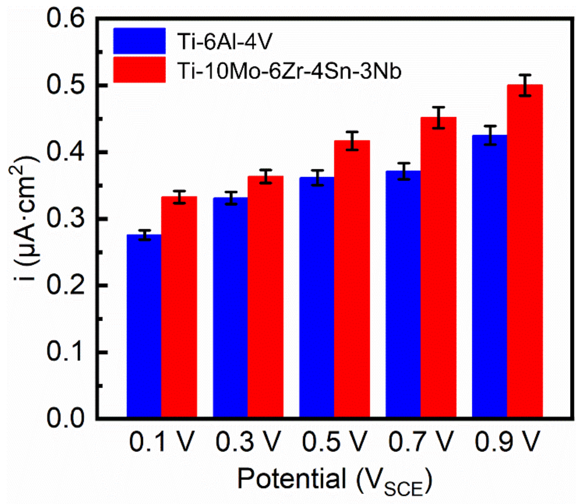
  • Ti–10Mo–6Zr–4Sn–3Nb shows higher passivation current density in both potentiodynamic polarization and potentiostatic polarization tests compared with Ti–6Al–4V. By Mott–Schottky examination, the result shows that more donors (mainly referring to oxygen vacancies) are presented in the passive film formed on Ti–10Mo–6Zr–4Sn–3Nb under the effect of the electric field. This is because more alloying elements are contained in Ti–10Mo–6Zr–4Sn–3Nb and such alloying elements and oxygen have a lower difference in the electronegativities compared with that between Ti and O. Therefore, more oxygen vacancies are produced in the passive film on Ti–10Mo–6Zr–4Sn–3Nb, resulting in a higher flux of oxygen vacancy, which finally leads to the higher passivation current density of Ti–10Mo–6Zr–4Sn–3Nb. This finding illustrates that the passive film on Ti–10Mo–6Zr–4Sn–3Nb is less protective compared with that on Ti–6Al–4V when applying an anodic potential in their passivation range.

Author Contributions

Conceptualization: J.C. and J.L.; Methodology: J.C.; Software: J.C. and X.Z.; Formal Analysis: S.Y., J.Z. and Z.D.; Data Curation: J.C. and F.D.; Writing—Original Draft Preparation: J.C.; Writing—Review & Editing: J.C. and J.L.; Writing—Manuscript finalization: J.C. and J.L.; Supervision: J.L.; Project Administration: J.C. and J.L.; Funding Acquisition: J.C. and J.L. All authors have read and agreed to the published version of this manuscript.

Funding

This work was financially supported by the National Natural Science Foundation of China (Nos. 51901193, 51861029, 51801162 and 32071327), Key Research and Development Program of Shaanxi (Program Nos. 2019GY-151, 2019GY-178, and 2020GY-251), Science and Technology Plan Project of Weiyang District in Xi’an City (201905), Xi’an Science and Technology Project (2020KJRC0141).

Data Availability Statement

The raw data supporting the conclusions of this article will be made available by the authors, without undue reservation.

Conflicts of Interest

The authors declare no conflict of interest, financial or otherwise.

References

  1. Zhang, L.-C.; Chen, L.-Y.; Wang, L. Surface Modification of Titanium and Titanium Alloys: Technologies, Developments and Future Interests. Adv. Eng. Mater. 2020, 22, 1901258. [Google Scholar] [CrossRef]
  2. Zhang, L.C.; Chen, L.Y. A Review on Biomedical Titanium Alloys: Recent Progress and Prospect. Adv. Eng. Mater. 2019, 21, 1801215. [Google Scholar] [CrossRef] [Green Version]
  3. Rabadia, C.D.; Liu, Y.J.; Zhao, C.H.; Wang, J.C.; Jawed, S.F.; Wang, L.Q.; Chen, L.Y.; Sun, H.; Zhang, L.C. Improved trade-off between strength and plasticity in titanium based metastable beta type Ti-Zr-Fe-Sn alloys. Mater. Sci. Eng. A 2019, 766, 138340. [Google Scholar] [CrossRef]
  4. Rabadia, C.D.; Liu, Y.J.; Chen, L.Y.; Jawed, S.F.; Wang, L.Q.; Sun, H.; Zhang, L.C. Deformation and strength characteristics of Laves phases in titanium alloys. Mater. Des. 2019, 179, 107891. [Google Scholar] [CrossRef]
  5. Pałka, K.; Pokrowiecki, R. Porous Titanium Implants: A Review. Adv. Eng. Mater. 2018, 20, 1700648. [Google Scholar] [CrossRef]
  6. Kang, L.; Yang, C. A Review on High-Strength Titanium Alloys: Microstructure, Strengthening, and Properties. Adv. Eng. Mater. 2019, 21, 1801359. [Google Scholar] [CrossRef]
  7. Marc, L.; Rack, H.J. Titanium alloys in total joint replacement—A materials science perspective. Biomaterials 1998, 19, 1621–1639. [Google Scholar]
  8. Zhang, L.-C.; Attar, H.; Calin, M.; Eckert, J. Review on manufacture by selective laser melting and properties of titanium based materials for biomedical applications. Mater. Technol. 2016, 31, 66–76. [Google Scholar] [CrossRef]
  9. Dai, N.; Zhang, J.; Chen, Y.; Zhang, L.-C. Heat treatment degrading the corrosion resistance of selective laser melted Ti-6Al-4V alloy. J. Electrochem. Soc. 2017, 164, C428–C434. [Google Scholar] [CrossRef]
  10. Polozov, I.; Sufiiarov, V.; Popovich, A.; Masaylo, D.; Grigoriev, A. Synthesis of Ti-5Al, Ti-6Al-7Nb, and Ti-22Al-25Nb alloys from elemental powders using powder-bed fusion additive manufacturing. J. Alloys Compd. 2018, 763, 436–445. [Google Scholar] [CrossRef]
  11. Ninomi, M.; Gong, B.; Kobayashi, T.; Ohyabu, T.; Toriyama, O. Fracture characteristics of Ti–6Al–4V and Ti–5Al–2.5 Fe with refined microstructure using hydrogen. Metal Mater. Trans. A 1995, 26, 1141–1151. [Google Scholar] [CrossRef]
  12. Cecchel, S.; Ferrario, D.; Cornacchia, G.; Gelfi, M. Development of Heat Treatments for Selective Laser Melting Ti6Al4V Alloy: Effect on Microstructure, Mechanical Properties, and Corrosion Resistance. Adv. Eng. Mater. 2020, 22, 2000359. [Google Scholar] [CrossRef]
  13. Huiskes, R.; Weinans, H.; Van Rietbergen, B. The Relationship Between Stress Shielding and Bone Resorption Around Total Hip Stems and the Effects of Flexible Materials. Clin. Orthop. Relat. Res. 1992, 124–134. [Google Scholar] [CrossRef] [Green Version]
  14. Liu, S.; Liu, J.; Liu, L.; Wang, R.L.W.; Ma, Y.; Zhong, W.L.; Zhang, L.C. Superelastic behavior of in-situ eutectic-reaction manufactured high strength 3D porous NiTi-Nb scaffold. Scripta Mater. 2020, 181, 121–126. [Google Scholar] [CrossRef]
  15. Azadbakht, R.; Almasi, T.; Keypour, H.; Rezaeivala, M. A new asymmetric Schiff base system as fluorescent chemosensor for Al3+ ion. Inorg. Chem. Commun. 2013, 33, 63–67. [Google Scholar] [CrossRef]
  16. Bottino, M.C.; Coelho, P.G.; Yoshimoto, M.; König, B.; Henriques, V.A.R.; Bressiani, A.H.A.; Bressiani, J.C. Histomorphologic evaluation of Ti–13Nb–13Zr alloys processed via powder metallurgy. A study in rabbits. Mater. Sci. Eng. C 2008, 28, 223–227. [Google Scholar] [CrossRef]
  17. Liu, Y.; Li, S.; Hou, W.; Wang, S.; Hao, Y.; Yang, R.; Sercombe, T.B.; Zhang, L.-C. Electron beam melted beta-type Ti–24Nb–4Zr–8Sn porous structures with high strength-to-modulus ratio. J. Mater. Sci. Technol. 2016, 32, 505–508. [Google Scholar] [CrossRef] [Green Version]
  18. Liu, Y.J.; Li, X.P.; Zhang, L.C.; Sercombe, T.B. Processing and properties of topologically optimised biomedical Ti–24Nb–4Zr–8Sn scaffolds manufactured by selective laser melting. Mater. Sci. Eng. A 2015, 642, 268–278. [Google Scholar] [CrossRef]
  19. Qin, P.; Chen, Y.; Liu, Y.-J.; Zhang, J.; Chen, L.-Y.; Li, Y.; Zhang, X.; Cao, C.; Sun, H.; Zhang, L.-C. Resemblance in corrosion behavior of selective laser melted and traditional monolithic β Ti-24Nb-4Zr-8Sn alloy. ACS Biomater. Sci. Eng. 2019, 5, 1141–1149. [Google Scholar] [CrossRef]
  20. Zhang, L.C.; Klemm, D.; Eckert, J.; Hao, Y.L.; Sercombe, T.B. Manufacture by selective laser melting and mechanical behavior of a biomedical Ti-24Nb-4Zr-8Sn alloy. Scripta Mater. 2011, 65, 21–24. [Google Scholar] [CrossRef]
  21. Wang, L.; Qu, J.; Chen, L.; Meng, Q.; Zhang, L.C.; Qin, J.; Zhang, D.; Lu, W. Investigation of Deformation Mechanisms in β-Type Ti-35Nb-2Ta-3Zr Alloy via FSP Leading to Surface Strengthening. Metall. Mater. Trans. A 2015, 46, 4813–4818. [Google Scholar] [CrossRef]
  22. Wang, L.; Xie, L.; Lv, Y.; Zhang, L.-C.; Chen, L.; Meng, Q.; Qu, J.; Zhang, D.; Lu, W. Microstructure evolution and superelastic behavior in Ti-35Nb-2Ta-3Zr alloy processed by friction stir processing. Acta Mater. 2017, 131, 499–510. [Google Scholar] [CrossRef] [Green Version]
  23. Saji, V.S.; Choe, H.C.; Brantley, W.A. An electrochemical study on self-ordered nanoporous and nanotubular oxide on Ti–35Nb–5Ta–7Zr alloy for biomedical applications. Acta Biomater. 2009, 5, 2303–2310. [Google Scholar] [CrossRef] [PubMed]
  24. Cheng, J.; Wang, H.; Li, J.; Gai, J.; Ru, J.; Du, Z.; Fan, J.; Niu, J.; Song, H.; Yu, Z. The effect of cold swaging deformation on the microstructures and mechanical properties of a novel metastable β type Ti-10Mo-6Zr-4Sn-3Nb alloy for biomedical devices. Front. Mater. 2020, 7, 228. [Google Scholar] [CrossRef]
  25. Guo, H.; Du, Z.; Wang, X.; Cheng, J.; Liu, F.; Cui, X.; Liu, H. Flowing and dynamic recrystallization behavior of new biomedical metastable β titanium alloy. Mater. Res. Exp. 2019, 6, 0865d0862. [Google Scholar] [CrossRef]
  26. Du, Z.; Guo, H.; Liu, J.; Cheng, J.; Zhao, X.; Wang, X.; Liu, F.; Cui, X. Microstructure evolution during aging heat treatment and its effects on tensile properties and dynamic Young’s modulus of a biomedical β titanium alloy. Mater. Sci. Eng. A 2020, 139677. [Google Scholar] [CrossRef]
  27. Chen, L.Y.; Shen, P.; Zhang, L.; Lu, S.; Chai, L.; Yang, Z.; Zhang, L.C. Corrosion behavior of non-equilibrium Zr-Sn-Nb-Fe-Cu-O alloys in high-temperature 0.01 M LiOH aqueous solution and degradation of the surface oxide films. Corros. Sci. 2018, 136, 221–230. [Google Scholar] [CrossRef]
  28. Chen, L.; Li, J.; Zhang, Y.; Zhang, L.C.; Lu, W.; Zhang, L.; Wang, L.; Zhang, D. Effects of alloyed Si on the autoclave corrosion performance and periodic corrosion kinetics in Zr-Sn-Nb-Fe-O alloys. Corros. Sci. 2015, 100, 651–662. [Google Scholar] [CrossRef]
  29. Chen, L.; Zeng, Q.; Li, J.; Lu, J.; Zhang, Y.; Zhang, L.-C.; Qin, X.; Lu, W.; Zhang, L.; Wang, L.; et al. Effect of microstructure on corrosion behavior of a Zr-Sn-Nb-Fe-Cu-O alloy. Mater. Des. 2016, 92, 888–896. [Google Scholar] [CrossRef]
  30. Bai, Y.; Gai, X.; Li, S.; Zhang, L.-C.; Liu, Y.; Hao, Y.; Zhang, X.; Yang, R.; Gao, Y. Improved corrosion behaviour of electron beam melted Ti-6Al–4V alloy in phosphate buffered saline. Corros. Sci. 2017, 123, 289–296. [Google Scholar] [CrossRef]
  31. Wang, J.L.; Liu, R.L.; Majumdar, T.; Mantri, S.A.; Ravi, V.A.; Banerjee, R.; Birbilis, N. A closer look at the in vitro electrochemical characterisation of titanium alloys for biomedical applications using in-situ methods. Acta Biomater. 2017, 54, 469–478. [Google Scholar] [CrossRef] [PubMed]
  32. Gai, X.; Bai, Y.; Li, J.; Li, S.; Hou, W.; Hao, Y.; Zhang, X.; Yang, R.; Misra, R.D.K. Electrochemical behaviour of passive film formed on the surface of Ti-6Al-4V alloys fabricated by electron beam melting. Corros. Sci. 2018, 145, 80–89. [Google Scholar] [CrossRef]
  33. Atapour, M.; Pilchak, A.L.; Frankel, G.S.; Williams, J.C. Corrosion behavior of β titanium alloys for biomedical applications. Mater. Sci. Eng. C 2011, 31, 885–891. [Google Scholar] [CrossRef]
  34. Guan, L.; Li, Y.; Wang, G.; Zhang, Y.; Zhang, L.-C. pH dependent passivation behavior of niobium in acid fluoride-containing solutions. Electrochim. Acta 2018, 285, 172–184. [Google Scholar] [CrossRef]
  35. Dai, N.; Zhang, L.-C.; Zhang, J.; Chen, Q.; Wu, M. Corrosion behavior of selective laser melted Ti-6Al-4V alloy in NaCl solution. Corros. Sci. 2016, 102, 484–489. [Google Scholar] [CrossRef]
  36. Chen, L.-Y.; Xu, T.; Lu, S.; Wang, Z.-X.; Chen, S.; Zhang, L.-C. Improved hardness and wear resistance of plasma sprayed nanostructured NiCrBSi coating via short-time heat treatment. Surf. Coat. Technol. 2018, 350, 436–444. [Google Scholar] [CrossRef]
  37. Zhang, L.C.; Xu, J.; Ma, E. Mechanically Alloyed Amorphous Ti50(Cu0.45Ni0.55)44–xAlxSi4B2 Alloys with Supercooled Liquid Region. J. Mater. Res. 2002, 17, 1743–1749. [Google Scholar] [CrossRef] [Green Version]
  38. Chen, L.; Li, J.; Zhang, Y.; Lu, W.; Zhang, L.C.; Wang, L.; Zhang, D. Effect of low-temperature pre-deformation on precipitation behavior and microstructure of a Zr-Sn-Nb-Fe-Cu-O alloy during fabrication. J. Nucl. Sci. Technol. 2016, 53, 496–507. [Google Scholar] [CrossRef]
  39. Chai, L.J.; Wang, S.Y.; Wu, H.; Guo, N.; Pan, H.C.; Chen, L.Y.; Murty, K.L.; Song, B. α→β Transformation characteristics revealed by pulsed laser-induced non-equilibrium microstructures in duplex-phase Zr alloy. Sci. China Technol. Sci. 2017, 60, 1255–1262. [Google Scholar] [CrossRef]
  40. Chen, L.Y.; Sang, P.; Zhang, L.; Song, D.; Chu, Y.Q.; Chai, L.; Zhang, L.C. Homogenization and growth behavior of second-phase particles in a deformed Zr-Sn-Nb-Fe-Cu-Si-O alloy. Metals 2018, 8, 759. [Google Scholar] [CrossRef] [Green Version]
  41. Xiang, K.; Chen, L.-Y.; Chai, L.; Guo, N.; Wang, H. Microstructural characteristics and properties of CoCrFeNiNbx high-entropy alloy coatings on pure titanium substrate by pulsed laser cladding. Appl. Surf. Sci. 2020, 517, 146214. [Google Scholar] [CrossRef]
  42. Khan, M.A.; Williams, R.L.; Williams, D.F. The corrosion behaviour of Ti-6Al-4V, Ti-6Al-7Nb and Ti-13Nb-13Zr in protein solutions. Biomaterials 1999, 20, 631–637. [Google Scholar] [CrossRef]
  43. Qin, P.; Liu, Y.; Sercombe, T.B.; Li, Y.; Zhang, C.; Cao, C.; Sun, H.; Zhang, L.-C. Improved Corrosion Resistance on Selective Laser Melting Produced Ti-5Cu Alloy after Heat Treatment. ACS Biomater. Sci. Eng. 2018, 4, 2633–2642. [Google Scholar] [CrossRef]
  44. Qin, X.; Guo, X.; Lu, J.; Chen, L.; Qin, J.; Lu, W. Erosion-wear and intergranular corrosion resistance properties of AISI 304L austenitic stainless steel after low-temperature plasma nitriding. J. Alloys Compd. 2017, 698, 1094–1101. [Google Scholar] [CrossRef]
  45. Sang, P.; Chen, L.-Y.; Zhao, C.; Wang, Z.-X.; Wang, H.; Lu, S.; Song, D.; Xu, J.-H.; Zhang, L.-C. Particle Size-Dependent Microstructure, Hardness and Electrochemical Corrosion Behavior of Atmospheric Plasma Sprayed NiCrBSi Coatings. Metals 2019, 9, 1342. [Google Scholar] [CrossRef] [Green Version]
  46. Zhang, L.; Chen, L.-Y.; Zhao, C.; Liu, Y.; Zhang, L.-C. Calculation of oxygen diffusion coefficients in oxide films formed on low-temperature annealed Zr alloys and their related corrosion behavior. Metals 2019, 9, 850. [Google Scholar] [CrossRef] [Green Version]
  47. Chen, L.; Huang, J.; Lin, C.; Pan, C.; Chen, S.; Yang, T.; Lin, D.; Lin, H.; Jang, J. Anisotropic response of Ti-6Al-4V alloy fabricated by 3D printing selective laser melting. Mater. Sci. Eng. A 2017, 682, 389–395. [Google Scholar] [CrossRef]
  48. Ralston, K.D.; Birbilis, N.; Davies, C.H.J. Revealing the relationship between grain size and corrosion rate of metals. Scripta Mater. 2010, 63, 1201–1204. [Google Scholar] [CrossRef]
  49. Chen, Y.; Zhang, J.; Dai, N.; Qin, P.; Attar, H.; Zhang, L.-C. Corrosion behaviour of selective laser melted Ti-TiB biocomposite in simulated body fluid. Electrochim. Acta 2017, 232, 89–97. [Google Scholar] [CrossRef] [Green Version]
  50. Guo, S.; Lu, Y.; Wu, S.; Liu, L.; He, M.; Zhao, C.; Gan, Y.; Lin, J.; Luo, J.; Xu, X.; et al. Preliminary study on the corrosion resistance, antibacterial activity and cytotoxicity of selective-laser-melted Ti6Al4V-xCu alloys. Mater. Sci. Eng. C 2017, 72, 631–640. [Google Scholar] [CrossRef]
  51. Zhang, H.; Man, C.; Wang, L.; Dong, C.; Wang, L.; Kong, D.; Wang, X. Different corrosion behaviors between α and β phases of Ti6Al4V in fluoride-containing solutions: Influence of alloying element Al. Corros. Sci. 2020, 169, 108605. [Google Scholar] [CrossRef]
  52. Kumar, S.; Sankara Narayanan, T.S.N.; Saravana Kumar, S. Influence of fluoride ion on the electrochemical behaviour of β-Ti alloy for dental implant application. Corros. Sci. 2010, 52, 1721–1727. [Google Scholar] [CrossRef]
  53. Dai, N.; Zhang, L.-C.; Zhang, J.; Zhang, X.; Ni, Q.; Chen, Y.; Wu, M.; Yang, C. Distinction in corrosion resistance of selective laser melted Ti-6Al-4V alloy on different planes. Corros. Sci. 2016, 111, 703–710. [Google Scholar] [CrossRef] [Green Version]
  54. Fernández-Domene, R.M.; Blasco-Tamarit, E.; García-García, D.M.; García-Antón, J. Passive and transpassive behaviour of Alloy 31 in a heavy brine LiBr solution. Electrochim. Acta 2013, 95, 1–11. [Google Scholar] [CrossRef]
  55. Armelin, E.; Moradi, S.; Hatzikiriakos, S.G.; Alemán, C. Designing Stainless Steel Surfaces with Anti-Pitting Properties Applying Laser Ablation and Organofluorine Coatings. Adv. Eng. Mater. 2018, 20, 1700814. [Google Scholar] [CrossRef] [Green Version]
  56. Wang, L.; Yu, H.; Wang, S.; Chen, B.; Wang, Y.; Fan, W.; Sun, D. Quantitative analysis of local fine structure on diffusion of point defects in passive film on Ti. Electrochim. Acta 2019, 314, 161–172. [Google Scholar] [CrossRef]
  57. Chen, L.-Y.; Cui, Y.-W.; Zhang, L.-C. Recent Development in Beta Titanium Alloys for Biomedical Applications. Metals 2020, 10, 1139. [Google Scholar] [CrossRef]
  58. Alves, A.P.R.; Santana, F.A.; Rosa, L.A.A.; Cursino, S.A.; Codaro, E.N. A study on corrosion resistance of the Ti-10Mo experimental alloy after different processing methods. Mater. Sci. Eng. C 2004, 24, 693–696. [Google Scholar] [CrossRef]
  59. Bai, Y.; Li, S.J.; Prima, F.; Hao, Y.L.; Yang, R. Electrochemical corrosion behavior of Ti-24Nb-4Zr-8Sn alloy in a simulated physiological environment. Appl. Surf. Sci. 2012, 258, 4035–4040. [Google Scholar] [CrossRef]
  60. Wang, Z.-X.; Chen, G.-Q.; Chen, L.-Y.; Xu, L.; Lu, S. Degradation Behavior of Micro-Arc Oxidized ZK60 Magnesium Alloy in a Simulated Body Fluid. Metals 2018, 8, 724. [Google Scholar] [CrossRef] [Green Version]
  61. Li, J.; Lin, X.; Wang, J.; Zheng, M.; Guo, P.; Zhang, Y.; Ren, Y.; Liu, J.; Huang, W. Effect of stress-relief annealing on anodic dissolution behaviour of additive manufactured Ti-6Al-4V via laser solid forming. Corros. Sci. 2019, 153, 314–326. [Google Scholar] [CrossRef]
  62. Li, J.; Lin, X.; Zheng, M.; Wang, J.; Guo, P.; Qin, T.; Zhu, M.; Huang, W.; Yang, H. Distinction in anodic dissolution behavior on different planes of laser solid formed Ti-6Al-4V alloy. Electrochim. Acta 2018, 283, 1482–1489. [Google Scholar] [CrossRef]
  63. Wu, G.; Wang, Y.; Liu, J.; Yao, J. Influence of the Ti alloy substrate on the anodic oxidation in an environmentally-friendly electrolyte. Surf. Coat. Technol. 2018, 344, 680–688. [Google Scholar] [CrossRef]
  64. Chen, K.; Zeng, L.; Li, Z.; Chai, L.; Wang, Y.; Chen, L.-Y.; Yu, H. Effects of laser surface alloying with Cr on microstructure and hardness of commercial purity Zr. J. Alloys Compd. 2019, 784, 1106–1112. [Google Scholar] [CrossRef]
  65. Dai, J.; Li, S.; Zhang, H. Microstructure and wear properties of self-lubricating TiB2-TiCxNy ceramic coatings on Ti-6Al-4V alloy fabricated by laser surface alloying. Surf. Coat. Technol. 2019, 369, 269–279. [Google Scholar] [CrossRef]
  66. Liu, S.; Han, S.; Zhang, L.; Chen, L.-Y.; Wang, L.; Zhang, L.; Tang, Y.; Liu, J.; Tang, H.; Zhang, L.-C. Strengthening mechanism and micropillar analysis of high-strength NiTi–Nb eutectic-type alloy prepared by laser powder bed fusion. Compos. Part B 2020, 200, 108358. [Google Scholar] [CrossRef]
  67. Li, G.; Wang, Y.; Qiao, L.; Zhao, R.; Zhang, S.; Zhang, R.; Chen, C.; Li, X.; Zhao, Y. Preparation and formation mechanism of copper incorporated micro-arc oxidation coatings developed on Ti-6Al-4V alloys. Surf. Coat. Technol. 2019, 375, 74–85. [Google Scholar] [CrossRef]
  68. Chen, L.-Y.; Wang, H.; Zhao, C.; Lu, S.; Wang, Z.-X.; Sha, J.; Chen, S.; Zhang, L.-C. Automatic remelting and enhanced mechanical performance of a plasma sprayed NiCrBSi coating. Surf. Coat. Technol. 2019, 369, 31–43. [Google Scholar] [CrossRef]
  69. Bacci, T.; Bertamini, L.; Ferrari, F.; Galliano, F.P.; Galvanetto, E. Reactive plasma spraying of titanium in nitrogen containing plasma gas. Mater. Sci. Eng. A 2000, 283, 189–195. [Google Scholar] [CrossRef]
  70. Kuo, T.Y.; Chin, W.H.; Chien, C.S.; Hsieh, Y.H. Mechanical and biological properties of graded porous tantalum coatings deposited on titanium alloy implants by vacuum plasma spraying. Surf. Coat. Technol. 2019, 372, 399–409. [Google Scholar] [CrossRef]
  71. Chen, L.-Y.; Xu, T.; Wang, H.; Sang, P.; Lu, S.; Wang, Z.-X.; Chen, S.; Zhang, L.-C. Phase interaction induced texture in a plasma sprayed-remelted NiCrBSi coating during solidification: An electron backscatter diffraction study. Surf. Coat. Technol. 2019, 358, 467–480. [Google Scholar] [CrossRef]
  72. Li, L.-H.; Kong, Y.-M.; Kim, H.-W.; Kim, Y.-W.; Kim, H.-E.; Heo, S.-J.; Koak, J.-Y. Improved biological performance of Ti implants due to surface modification by micro-arc oxidation. Biomaterials 2004, 25, 2867–2875. [Google Scholar] [CrossRef] [PubMed]
  73. Ohwada, K. On the pauling electronegativity scales-II. Polyhedron 1984, 3, 853–859. [Google Scholar] [CrossRef]
  74. Ohwada, K. On the Pauling electronegativity scales—I. Polyhedron 1983, 2, 423–424. [Google Scholar] [CrossRef]
  75. Guan, W.; Zhang, L.; Wang, C.; Wang, Y. Theoretical and experimental investigations of the thermoelectric properties of Al-, Bi- and Sn-doped ZnO. Mater. Sci. Semicond. Process. 2017, 66, 247–252. [Google Scholar] [CrossRef]
  76. Bell, B.D.C.; Murphy, S.T.; Grimes, R.W.; Wenman, M.R. The effect of Nb on the corrosion and hydrogen pick-up of Zr alloys. Acta Mater. 2017, 132, 425–431. [Google Scholar] [CrossRef] [Green Version]
  77. Reddy, K.P.; Mhamane, N.B.; Ghosalya, M.K.; Gopinath, C.S. Mapping Valence Band and Interface Electronic Structure Changes during the Oxidation of Mo to MoO3 via MoO2 and MoO3 Reduction to MoO2: A NAPPES Study. J. Phys. Chem. C 2018, 122, 23034–23044. [Google Scholar] [CrossRef]
  78. Chen, L.; Li, J.; Zhang, Y.; Zhang, L.C.; Lu, W.; Wang, L.; Zhang, L.; Zhang, D. Zr-Sn-Nb-Fe-Si-O alloy for fuel cladding candidate: Processing, microstructure, corrosion resistance and tensile behavior. Corros. Sci. 2015, 100, 332–340. [Google Scholar] [CrossRef]
  79. Zhang, L.C.; Jia, Z.; Lyu, F.; Liang, S.X.; Lu, J. A review of catalytic performance of metallic glasses in wastewater treatment: Recent progress and prospects. Prog. Mater. Sci. 2019, 105, 100576. [Google Scholar] [CrossRef]
  80. Liu, S.; Zhang, Z.; Xia, J.; Chen, Y. Effect of Hydrogen Precharging on Mechanical and Electrochemical Properties of Pure Titanium. Adv. Eng. Mater. 2020, 22, 1901182. [Google Scholar] [CrossRef]
  81. Yang, H.-Y.; Wang, Z.; Yue, X.; Ji, P.-J.; Shu, S.-L. Simultaneously improved strength and toughness of in situ bi-phased TiB2–Ti(C,N)–Ni cermets by Mo addition. J. Alloys Compd. 2020, 820, 153068. [Google Scholar] [CrossRef]
Figure 1. XRD patterns of Ti–10Mo–6Zr–4Sn–3Nb and Ti–6Al–4V samples.
Metals 11 00011 g001
Figure 2. Optical microstructures of (a) etched Ti–10Mo–6Zr–4Sn–3Nb and (b) Ti–6Al–4V samples. GBs indicates grain boundaries.
Metals 11 00011 g002
Figure 3. Open circuit potentials for Ti–10Mo–6Zr–4Sn–3Nb and Ti–6Al–4V.
Metals 11 00011 g003
Figure 4. Potentiodynamic polarization curves of Ti–10Mo–6Zr–4Sn–3Nb and Ti–6Al–4V in Hank’s solutions at 37 °C.
Metals 11 00011 g004
Figure 5. Electrochemical impedance spectroscopy of Ti–10Mo–6Zr–4Sn–3Nb and Ti–6Al–4V in Hank’s solutions at 37 °C: (a) Nyquist plots and (b) Bode phase angle plots. The inset is the equivalent electrical circuit for fitting the data.
Metals 11 00011 g005
Figure 6. Quasi-steady state current density for Ti–10Mo–6Zr–4Sn–3Nb and Ti–6Al–4V at various applied potentials after 30 min potentiostatic polarization in Hank’s solution at 37 °C.
Metals 11 00011 g006
Figure 7. Mott–Schottky curves of (a) Ti–10Mo–6Zr–4Sn–3Nb and (b) Ti–6Al–4V.
Metals 11 00011 g007
Figure 8. Semi-conductive properties of passive films formed on Ti–10Mo–6Zr–4Sn–3Nb and Ti–6Al–4V after 30 min potentiostatic polarization at 0.6‒1 VSCE: (a) donor density, (b) thickness of passive film, (c) diffusion coefficient of oxygen vacancy, and (d) diffusion flux.
Metals 11 00011 g008
Table 1. Compositions of both Ti–10Mo–6Zr–4Sn–3Nb and Ti–6Al–4V alloys used in this work (wt%).
TiMoZrSnNbAlV
Balance10.11 ± 0.315.71 ± 0.244.32 ± 0.182.83 ± 0.18--
Balance----5.94 ± 0.214.28 ± 0.25
Table 2. Fitting results of potentiodynamic polarization curves of Ti–10Mo–6Zr–4Sn–3Nb and Ti–6Al–4V in Hank’s solutions at 37 °C. Ecorr is the corrosion potential; Icorr is the corrosion current density; Epp is the passivation potential, Ipp is the passive current density.
SampleEcorr (VSCE)Icorr (μA·cm−2)Epp (VSCE)Ipp (μA·cm−2)
Ti–10Mo–6Zr–4Sn–3Nb−0.430 ± 0.0120.007 ± 0.0020.024 ± 0.0143.664 ± 0.438
Ti–6Al–4V−0.504 ± 0.0440.020 ± 0.008−0.133 ± 0.0123.111 ± 0.172
Table 3. Fitting results of electrochemical impedance spectra for Ti–10Mo–6Zr–4Sn–3Nb and Ti–6Al–4V after the OCP tests in Hank’s solutions at 37 °C. Rf means film resistance, Rct indicates charge transfer resistance, CPE describes charge transfer capacitance, n1 and n2 are the exponents of CPE1 and CPEdl, and χ2 is the sum of squares of the differences between theoretical and experimental points.
SampleRs
(Ω cm2)
Rf
(Ω cm2)
CPE1 × 10−6 (F·cm−2)n1Rct (MΩ cm2)CPEdl × 10−5 (F·cm−2)n2χ2
Ti–10Mo–6Zr–4Sn–3Nb18.10 ± 0.5132.95 ± 2.1224.41 ± 0.26 0.8995 ± 0.00181.3297 ± 0.08581.307 ± 0.080.8870 ± 0.00226.67 × 10−4
Ti–6Al–4V13.77 ± 1.016.16 ± 0.478.35 ± 0.61 0.8784 ± 0.01170.7367 ± 0.00823.138 ± 0.13 0.9136 ± 0.00674.24 × 10−4
Publisher’s Note: MDPI stays neutral with regard to jurisdictional claims in published maps and institutional affiliations.

