Article

Local-Induction-Heating Bending Process of B1500HS Thin-Walled Rectangular Steel Tubes: A Simulation and Experimental Investigation

School of Mechatronics Engineering, Harbin Institute of Technology, Harbin 150000, China
*
Author to whom correspondence should be addressed.
Metals 2021, 11(1), 132; https://doi.org/10.3390/met11010132
Submission received: 13 December 2020 / Revised: 30 December 2020 / Accepted: 7 January 2021 / Published: 11 January 2021

Abstract

:
To lighten and stiffen the structural components used in automobile bodies, the variable curvature local-induction-heating bending forming (VC-LIHBF) technology was developed. However, few studies have been conducted on the optimization of the structural and geometric parameters of the inductor and the parameters of the LIHBF process. This paper focuses on the improvement of the cross-sectional distortion and the forming limit of the thin-walled rectangular steel tubes (TWRSTs) without the mandrel support. In this work, a coupled thermo-mechanical finite element analysis (FEA) method is developed to investigate the structural and geometric parameters of the inductor and the deformation behavior during VC-LIHBF. The temperature distribution is calculated by the electromagnetic and heat transfer analysis, and the stress distribution is obtained by the deformation analysis. Experiments were carried out to validate the reliability of the proposed finite element model (FEM). The results indicate that the forming quality of the TWRST is significantly affected by the structural and geometric parameters of the inductor, the feed rate of the tube, the push speed of the bending roller and the distance between the inductor and the bending roller. The appropriate inductor and process parameters for a B1500HS TWRST were determined. The findings of this study may provide important guidance for practical manufacturing via the LIHBF process.

1. Introduction

To improve both energy efficiency and crash safety, the automotive industry has been focusing on the application of high-strength structures to lighten vehicles in recent years. Consequently, the local-induction-heating bending forming (LIHBF) and direct quench processing technologies for tube manufacturing, which are inexpensive, highly efficient and yield higher-quality products [1,2], have been developed for these two reasons. The production of automobile components with ultra-high tensile strength and a hollow tubular structure has become one of the frontier fields in the research and development of advanced plastic forming technology [3].
Scholars have focused on the LIHBF process for the manufacturing of thick-walled and large-diameter tubes [4,5,6,7], but little attention has been paid to the use of the LIHBF process to manufacture thin-walled tubes, particularly to the variable curvature LIHBF (VC-LIHBF) process for manufacturing of thin-walled rectangular steel tubes (TWRSTs).
Many factors, such as the temperature distribution and process parameters, have an impact on the LIHBF forming quality and limit of the bent tubes. The reasonable temperature distribution is key to the improvement of the LIHBF quality of a tube. Kubota et al. [8] developed a simulation framework that takes into account both induction heating and phase transformation to calculate the temperature distribution of the tube in the LIHBF process, and the results were in good agreement with the experimental results. However, this study did not consider the influences of the structural and geometric parameters of the inductor on the temperature distribution of the tube and the efficiency of the heating tube. Appropriate LIHBF process parameters are important for the improvement of the forming quality and limit of the bent tubes. Some studies have been conducted on the optimization of the LIHBF process. For example, Guo et al. [9] and Ma et al. [10] determined the appropriate LIHBF process parameters of a P11 alloy circular tube, namely the axial push velocity, the current density and the heating frequency, via both simulation results and experimental measurements. Kathayat et al. [11] optimized the LIHBF process parameters of an API 5L X65MS/MO circular pipe, namely the bending speed, water flow rate, water pressure and air pressure, via the mechanical tests and microstructural analysis of the bent pipe. However, these studies did not consider the LIHBF process parameters, namely the clearance between the inductor and the tube, and the push speed of the bending roller.
In the present study, a high-temperature constitutive model of B1500HS material is developed based on the least-square regression analysis of the true stress–strain curves. The structural and geometric parameters of the inductor are determined by electromagnetic and heat transfer numerical simulations. Then, the temperature distribution and the stress distribution of the TWRST in the LIHBF process and the influence of the process parameters on the LIHBF quality of the TWRST are investigated via the numerical simulation and bending forming experiments. The findings of this study provide a better cognition for the cross-sectional deformation and wrinkling of a rectangular tube in the LIHBF process. In addition, the established coupled thermo-mechanical finite element model (FEM) can be used to investigate the effects of other parameters on the bending forming limit and quality of a rectangular tube during the LIHBF process.

2. Methodology

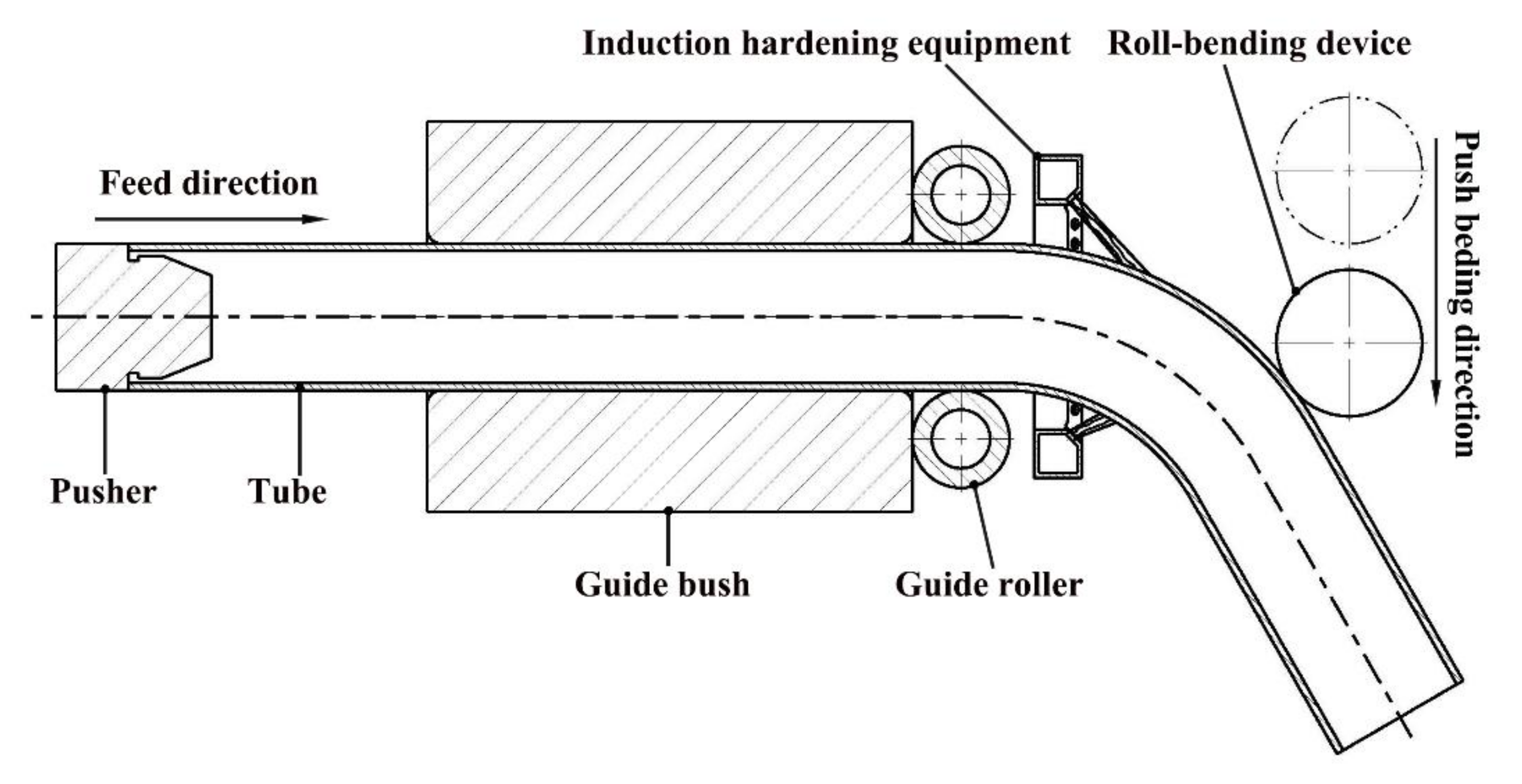
2.1. Process Principle

Variable curvature local-induction-heating bending forming (VC-LIHBF) technology is a consecutive forming technique that allows for the simultaneous bending forming and hardening of a hollow tube. The schematic of push bending with the LIHBF process is shown in Figure 1. The machine consists of four components, namely a pusher, a guide device, an induction hardening equipment and a roll-bending device. In the LIHBF process, the TWRST is subjected to the contact force of different dies, such as a guide bush, a guide roller and a pusher. Firstly, the TWRST is fed in the axial direction and heated to a temperature that is higher than the complete austenitizing temperature locally. Simultaneously, the TWRST is bent by the roll-bending device. After heating, the tube is cooled to room temperature with cooling water.

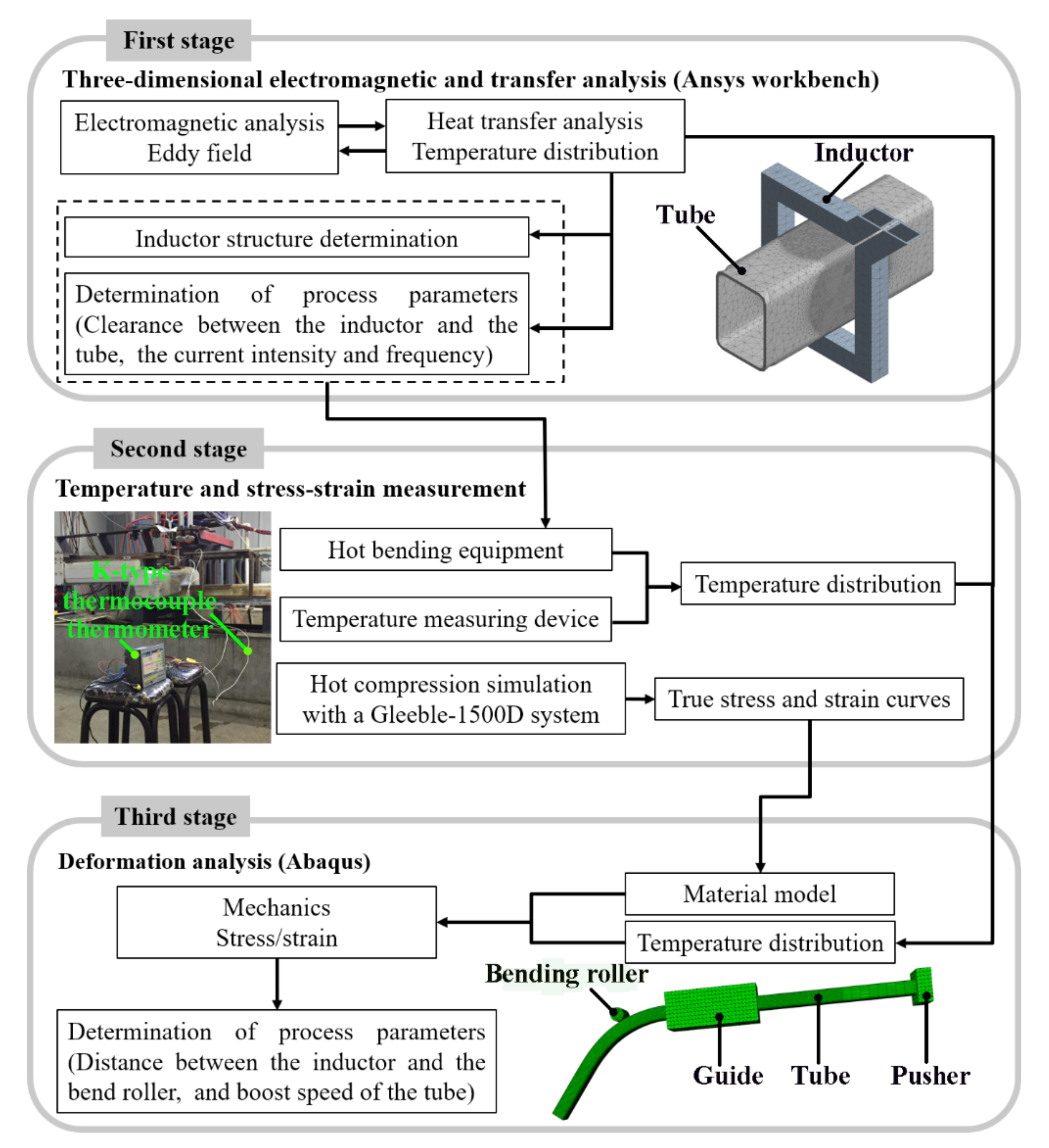
2.2. Analysis Procedure

In this research, the simulation of the LIHBF process of the TWRST was performed with a coupled thermo-mechanical FEM. The analysis procedure shown in Figure 2 consisted of the following three stages.
In the first stage, the temperature distribution was calculated by electromagnetic and heat transfer analyses, in which, the eddy fields under different working conditions were obtained by Maxwell software. Next, the transformation from the eddy field to the temperature distribution was achieved via the thermal module in ANSYS Workbench software. The structure and geometric parameters of the inductor and the clearance between the inductor and the TWRST, as well as the current intensity and frequency, were determined by the temperature distribution calculated previously.
In the second stage, local-induction-heating bending equipment was constructed according to the simulation results. The real temperature distribution of the TWRST used for the verification of the simulation results was measured by a k-type thermocouple thermometer. Hot compression tests were then carried out on a Gleeble-1500D thermal simulation testing machine, and the true stress–strain curves of B1500HS steel under different deformation conditions were obtained.
In the third stage, the obtained temperature distribution was mapped to integration points in finite elements, and the constitutive equation of B1500HS material was developed by the regression analysis of the true stress–strain curves, and deformation analysis was carried out. The dynamic explicit FEM [12,13] code ABAQUS/ Temp-disp/Explicit was used at this stage. The distance between the bending roller and the inductor, the feed rate of the tube, and the push speed of the bending roller are determined by a deformation analysis.

3. FEM Modeling

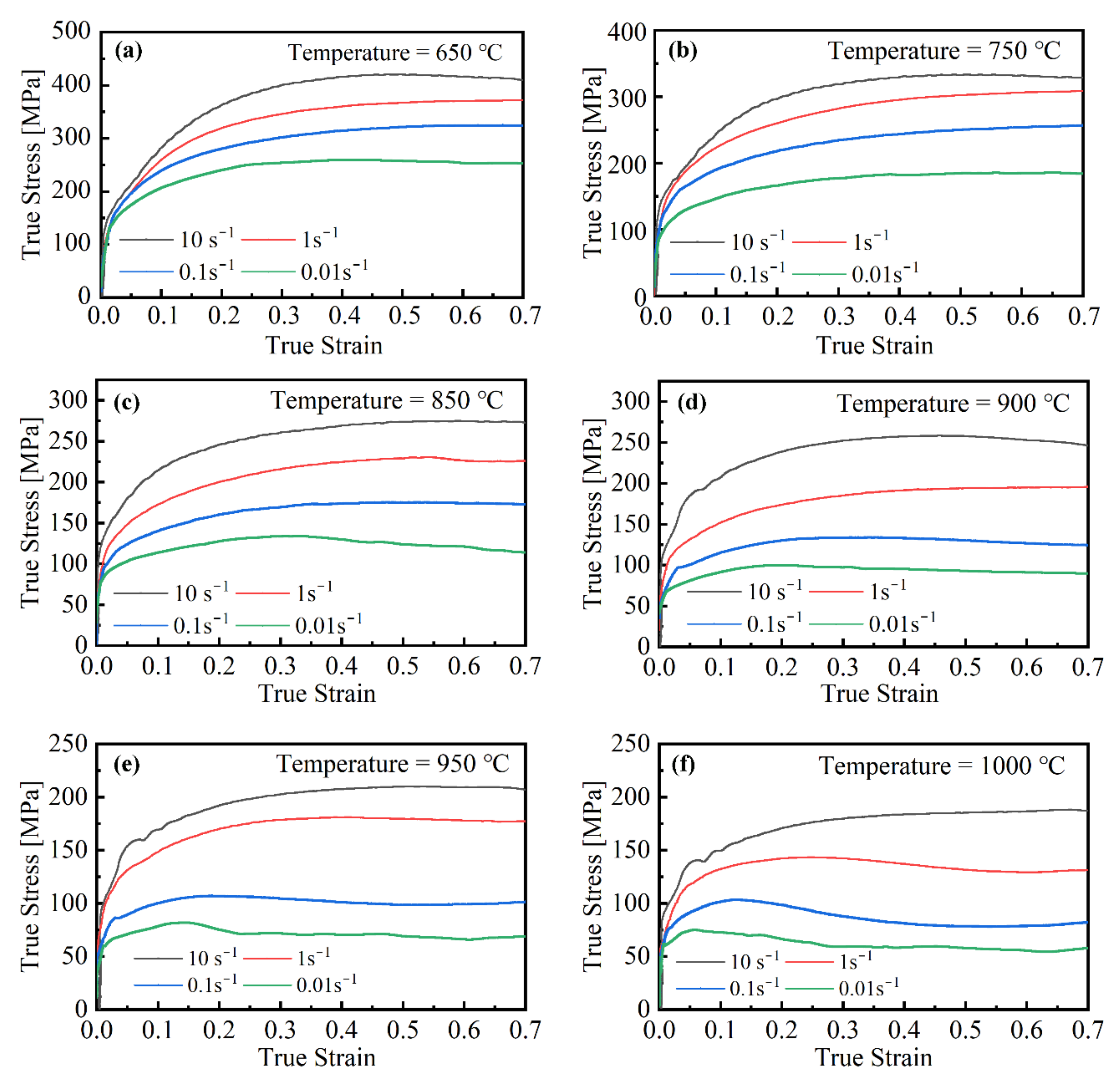
3.1. Materials Model and Friction Model

The material properties are crucial factors for achieving a reliable FE simulation. Thus, the attributes for the simulation should be carefully chosen. The detailed compositions and thermophysical parameters of B1500HS steel are respectively described in Table 1 and Table 2.
The lower the relative permeability, the higher the energy required for heating and the slower the heating rate. The relative permeability μ r = μ / μ o = B / H / μ o (where μ is permeability (H/m), μ o is vacuum permeability (H/m), B is the magnetic flux density (T), H is the magnetic field strength (A/m)). To obtain the relative permeability, the saturation test of the lifting phase of the B1500HS steel hysteresis loop at 27, 127, 227, 327, 427, 527, and 627 °C were carried out by a physical property measurement system (PPMS). The magnetic field strength was set as ± 5 T and the scanning speed was 100 Oe/s. The B-H curves of B1500HS steel at different temperatures were obtained, as shown in Figure 3. When the temperature is higher than the Curie temperature, the ferromagnetic material loses its magnetism, and its relative permeability is 1.
To construct the constitutive model used in the FEM, cylindrical specimens that were 5 mm in diameter and 7.5 mm in length were prepared to perform the hot compression tests on a Gleeble-1500D thermal simulation testing machine (DSI Inc., St. Paul, MN, USA). A NiCr-NiSi thermocouple, which was used to measure and control the specimen temperature during the test, was welded in the center of the specimen by the spot-welder, and a tantalum foil with a thickness of 0.1 mm and a graphite lubricant were placed between the specimen and pressure die to reduce the friction. The specimens were heated to 1000 or 950 °C at a speed of 10 °C/s and held there for 4 min to ensure the complete austenization of the specimens. Then, the specimens were compressed at the strain rates of 0.01, 0.1, 1 and 10 s−1. The specimens were then heated to 950 °C at a speed of 10 °C/s and held there for 4 min. Next, the specimens were cooled to 900, 850, 750 or 650 °C at a speed of 170 °C/s, subsequently, the specimens are compressed at strain rates of 0.01, 0.1, 1 and 10 s−1. The amount of compression was 55% of the length of the specimen. The thermal-mechanical simulator and the specimens before and after compression are presented in Figure 4, and the true stress–strain curves under the different deformation conditions are shown in Figure 5.
The deformation of the metal under high temperatures is a thermally activated process, which is controlled by the activation energy. High-temperature flow stress is sensitive to the strain rate and temperature [15], and the Arrhenius equation is widely used to describe the relationship between them [16,17,18]:
ε ˙ = A [ sinh ( α σ ) ] n exp   ( Q R T )
According to the definition of a hyperbolic sine function, Equation (1) can be expressed as follows:
σ = 1 α ln ε ˙ exp   ( Q R T ) A 1 n + ε ˙ exp   ( Q R T ) A 2 n + 1 1 2
where σ is stress (MPa), ε ˙ is the strain rate, n is the stress exponent, T is the absolute temperature (K), R is the molar gas constant (8.31 J/(mol·K)), Q is the hot deformation activation energy (kJ/mol), and A and α are the material constants.
The material constants (α = 0.0059, A = 3.39 × 10¹¹), stress exponent (n = 6.59), and activation energy (Q = 149 kJ/mol) of B1500HS steel were determined by the Equation (1) and the least-squares regression analysis of the true stress–strain curves [15,19,20,21], and the constitutive equation of B1500HS steel is constructed as follows:
σ = 169.5 ln ε ˙ exp 149 / 8.31 T 3.39 × 10 11 0.15 + ε ˙ exp 149 / 8.31 T 3.39 × 10 11 0.3 + 1 1 2
In constitutive Equation (3), the yield function type follows the Huber–Mises–Hencky criteria and the hardening rule is assumed to be isotropic. The important material parameters were imported into the ABAQUS preprocessor.
The Coulomb friction model was chosen to describe the friction between different dies and the TWRST. The friction coefficient between the bending roller and the TWRST was 0.08 and the friction coefficient between the guide bush and the TWRST was 0.1 [22].

3.2. FEM Model and Resolution of Key Problems

In the FEM of a B1500HS TWRST (Figure 2), the original geometrical section size of the B1500HS TWRST was 30 mm (Width) × 40 mm (Height) × 1.5 mm (Thickness) with an outer fillet with a 4-mm radius.
The main settings in the three-dimensional electromagnetic and heat transfer analyses were as follows. In the electromagnetic analysis, the maximum number of passes was set as 10, the error convergence was set as 1%, the maximum length of elements was 15 mm, and the number of element layers was 2 in mesh operations. In the heat transfer analysis, tetrahedrons and patch conforming methods were adopted. Moreover, the sphere of influence was selected as the type of mesh with a size of 0.5 mm, and the convection film coefficient between the air and the TWRST was set as 5 × 10⁻⁶ W/mm2·°C.
In the deformation analysis, the B1500HS TWRST was defined as a deformable body with a four-node thermo-mechanical coupling curved surface using a thin shell element S4RT to describe curved faces with smooth contact geometries. The number of thickness integration points was selected as 5, the length of the tube was 900 mm, and the total number of meshing elements was selected as 19,584. The pusher, guide bush, and bending roller were all defined as rigid bodies using the ten-node modified tetrahedral element C3D10M to describe contact curved faces.
“Surface-to-surface contact” was used to define the contact between the tube and dies. The “penalty contact method” was selected as the mechanical constraint formulation, and the “finite sliding” was selected as the sliding formulation. The bending angle of the bent tube was set as 90°. The guide bush was constrained in all degrees of freedom, and the bending roller could only translate along the Y-axis, and rotate around the Z-axis.
The reasonable temperature distribution is key to the achievement of the good forming quality of a TWRST in the LIHBF process. The temperature distribution in the thickness direction has only minor effects on thin-walled tubes because of the good thermal conductivity of the metal. Thus, it can be assumed that the temperature fails to be uniformly distributed in the thickness direction. In the LIHBF process, the temperature of the heating zone was measured by a thermocouple. The measured peak temperature ranged between 981 and 1046 °C, and was combined with the results of the three-dimensional electromagnetic and heat transfer analyses. Thus, the highest temperature of the LIHBF zone was set at 940 °C in the deformation analysis.

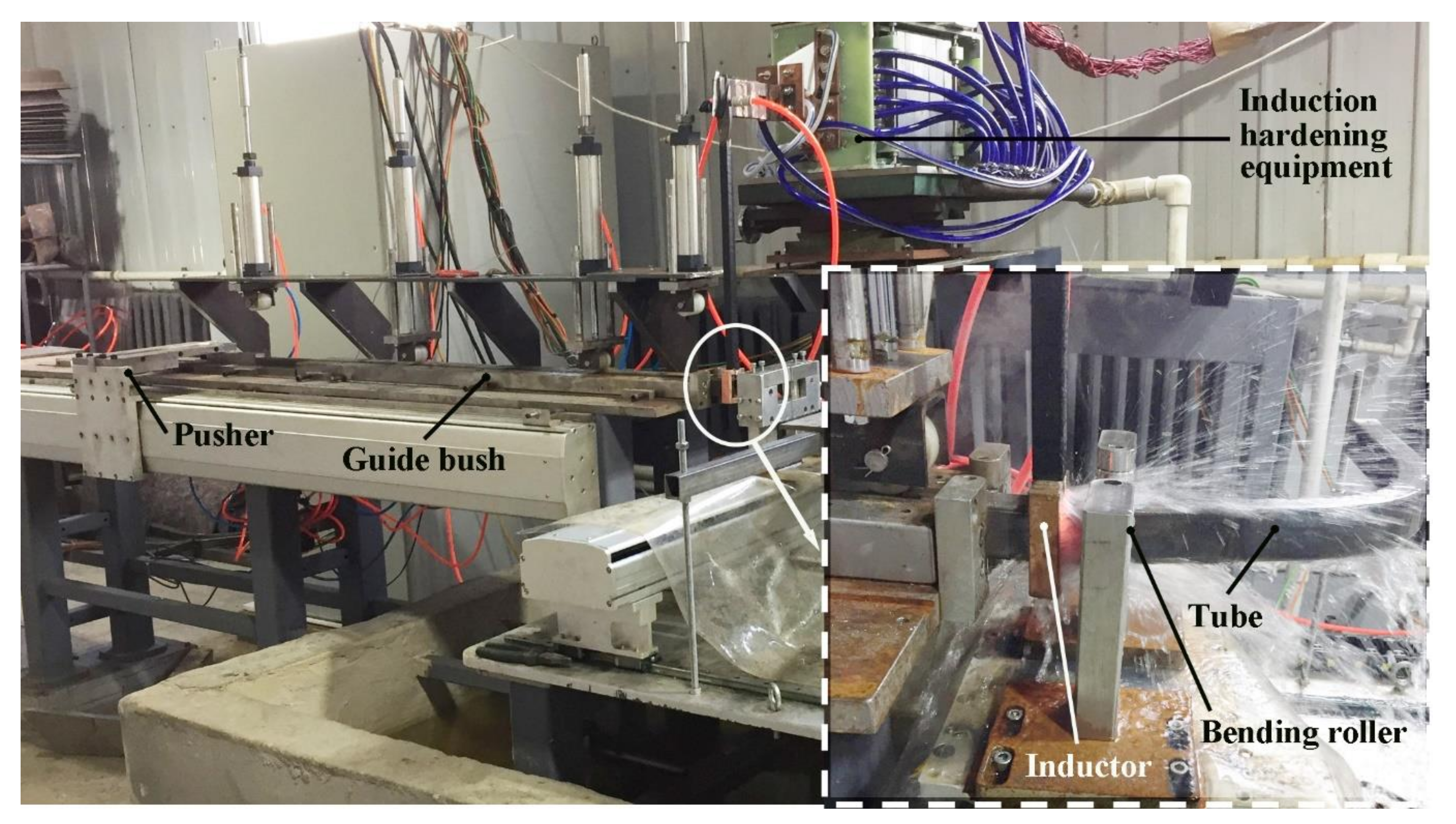
4. Local-Induction-Heating Bending Experiment

To verify the accuracy of the numerical simulation results, forming experiments were carried out using a numerically control LIHBF machine with the same forming principle and dies structures like those used in the simulation, as shown in Figure 6.
The experimental conditions are listed in Table 3. The inductor served not only as a heat source for induction heating, but also as a cooling device that sprayed cooling water. The cooling water was fed into the inductor, which had a downward spray hole drilled on its sidewall. The experimental results of hot bending forming were compared under the condition of the tensile strength of the hot bending forming parts being nearly equal to or greater than 1500 MPa.
The VC-LIHBF process is a continuous bending process in which the bending radius of the tube can be changed to any arbitrary value between the infinite and minimum values. Lines were separately drawn in the positions of the starting bending point and the 90° bend of the bent tube. With the intersection point as the center of circle, a measurement point was collected every 10°, as shown in Figure 7.
The geometric parameters of each measured section of the rectangular steel tube are separately denoted by the mid-surface height (h0) and width (b0), as shown in Figure 8. The distortion in the width direction of each measured section is indicated as δ b m (m = 1, 2 … 13), where δ b max is the maximum values of δ b m . The distortion in the height direction of each measured section is recorded as δ h n (n = 15, 16 … 23), where δ h max is the maximum values of δ h n . The values of δ b m and δ h n are respectively expressed by Equation (4) and Equation (5), respectively.
δ b m = b 0 b m b 0 × 100 %
δ h n = h 0 h n h 0 × 100 %
The B1500HS TWRST with a minimum bending radius was obtained, and the thinning of wall thickness and the cross-sectional deformation of the tube could be well controlled. The results presented in Figure 9 reveal that the section distortion rate in the width direction was higher than that in the height direction. The error of the distortion rate in the height direction between the experimental and simulation results was within 0.7%, while that in the width in the width direction was high. The wall thickness error was within 0.08 mm, and the maximum wall thickness reduction rate was less than 6.7%. The experimental and simulation results exhibit the overall consistency, and the comparison results indicate that the FEM is reliable.

5. Results and Discussion

5.1. Structural Analysis of the Inductor

The structure of the inductor has a major influence on the temperature distribution of the TWRST and the heating efficiency (the efficiency of heating the TWRST). The electrical resistance of the inductor must be reduced to prevent the excessive heat loss caused by the overheating of the inductor itself. According to the empirical formula, the wall thickness of the inductor should be greater than 1.57 δ copper , and T3 copper was used for the inductor material in the research. Additionally, the wall thickness of the inductor was calculated as δ copper = 503 , 000 ρ / ( μ r f ) =   0.562   mm [23], (where the relative permeability μ r =   1 , resistivity ρ copper   =   1.75   ×   10 8   Ω m , and current frequency f =   14 , 000   Hz ) [23], and the wall thickness of the inductor was set as 1 mm. The current area of the rectangular copper tube was closer to the heated tube than the round copper tube; thus, the distance between the rectangular inductor and the copper tube was smaller than the gap of the same round copper tube. Therefore, a rectangular single-turn inductor was used in the LIHBF process of the TWRST.
Considering the influences of the distance between the current input and output terminals, the center of the TWRST, and the shape of the inductor on the magnetic field distribution, different types of inductors were designed as shown in Figure 10. The cross-sectional dimension of the inductors was 10 × 10 × 1 mm3, and the clearance between the inductor and the TWRST was 8 mm. The current input and output terminals of the inductor are respectively located on the short side (Figure 10a), the long side (Figure 10b), and the diagonal (Figure 10c,d) of the inductors. The current input and output terminals of the inductors shown in Figure 10c,d were both located on the diagonal of the inductor; and the difference is that the clearance between the inductor shown in Figure 10d and the TWRST was uniform, while the clearance at the rounded corners of the inductor shown in Figure 10c was larger than that on the straight sides.
The temperature distributions of a rectangular steel tube based on different inductor structures (input current 4000 A; current frequency: 14,000 Hz and heating time: 2.65 s), as shown in Figure 11, reveal that the circumferential temperature distribution of the rectangular steel tube in the induction heating zone was uneven, and that the highest temperature was at the round corners. This is due to the uneven circumferential magnetic field intensity of the rectangular tube, the magnetic induction intensity of which was the strongest at the round corners [14]. The peak temperature of the rectangular steel tube based on the inductor with structure c was 1040.4 °C, exhibiting the highest heating efficiency and a relatively uniform circumferential temperature distribution. The peak temperature of the rectangular steel tube based on the inductor with structure d was 1016.3 °C, exhibiting a heating efficiency that is similar to that of the inductor with structural c. The penetration heating method of induction heating greatly reduces the non-uniformity of the axial temperature distribution of the tube. The non-uniformity of the temperature distribution is mainly due to the circumferential non-uniformity of the temperature distribution. Therefore, the temperature distribution of the middle section of the rectangular steel tube can clearly reflect the circumferential temperature distribution. The temperature distribution uniformity of the rectangular steel tube based on the inductor with structure c with a temperature difference of 170.45 °C is better than that of the rectangular steel tube based on the inductor with structure d with a temperature difference of 270.65 °C (Figure 12). Therefore, the inductor with structural c is more reasonable than the other three inductors.
Figure 13 presents the temperature distribution when the average temperature of the middle section of the TWRST was 942 ± 1 °C (input current: 4000 A; current frequency: 14,000 Hz; inductor with structure c with different widths). It respectively took 3.01, 2.65, 3.54 and 3.56 s to reach the corresponding target average temperature, and the heating efficiency of the inductor with a width of 10 mm was the highest. The results in Figure 14 demonstrate that the minimum temperature difference of the steel tube based on the inductor with the width of 10 mm was 170.45 °C, while that with the width of 5 mm was 264.25 °C. When the width of the inductor is less than 10 mm, reducing the width of the inductor will shorten the width of the hot bending forming zone, which is conducive to obtaining a bent tube with a smaller bending radius. However, if the width of the inductor is too small, it will reduce the strength, stability, cooling efficiency and service life of the inductor, and the heating uniformity will be poor. Within a certain range, the width of the hot bending forming zone increases with the increase in the width of the inductor, but the temperature distribution uniformity and heating efficiency of the heating area cannot be guaranteed, which is not conducive to obtaining a bent tube with a smaller bending radius. In addition, it is necessary to increase the heating power accordingly, which increases the production cost. Based on the preceding analysis, the width of the inductor was set as 10 mm.

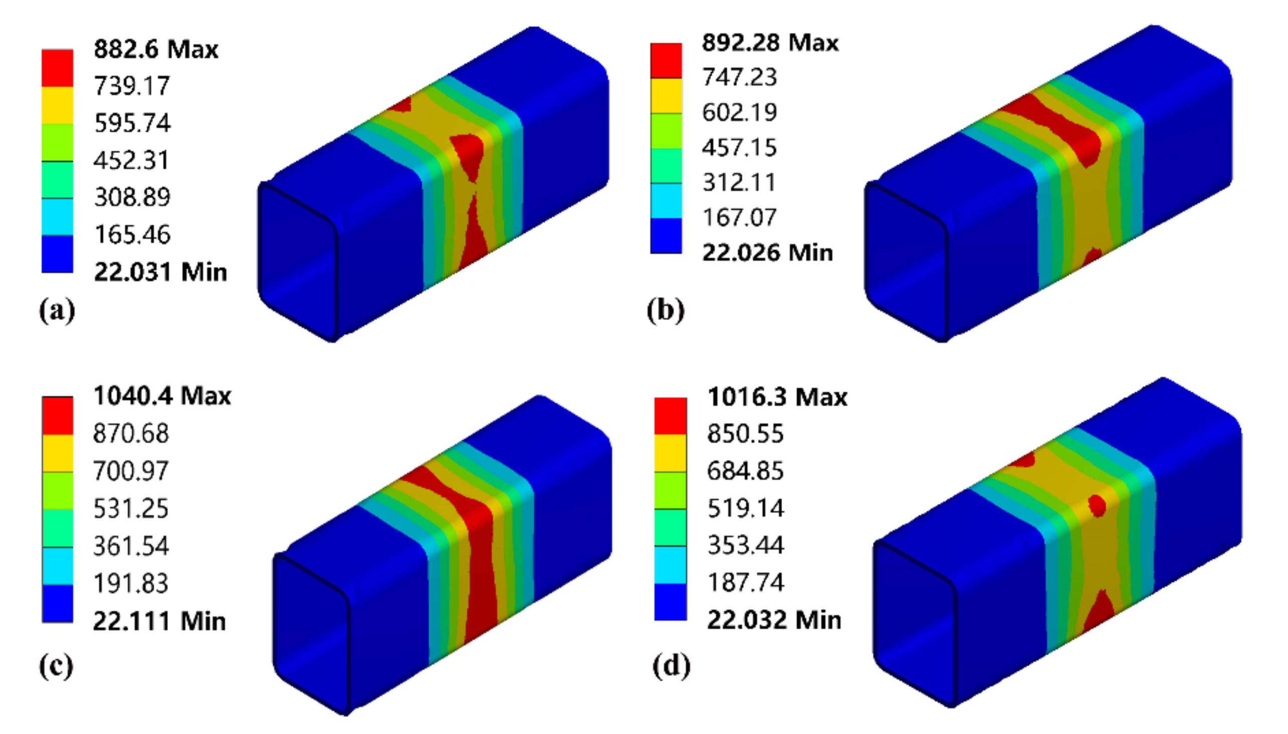
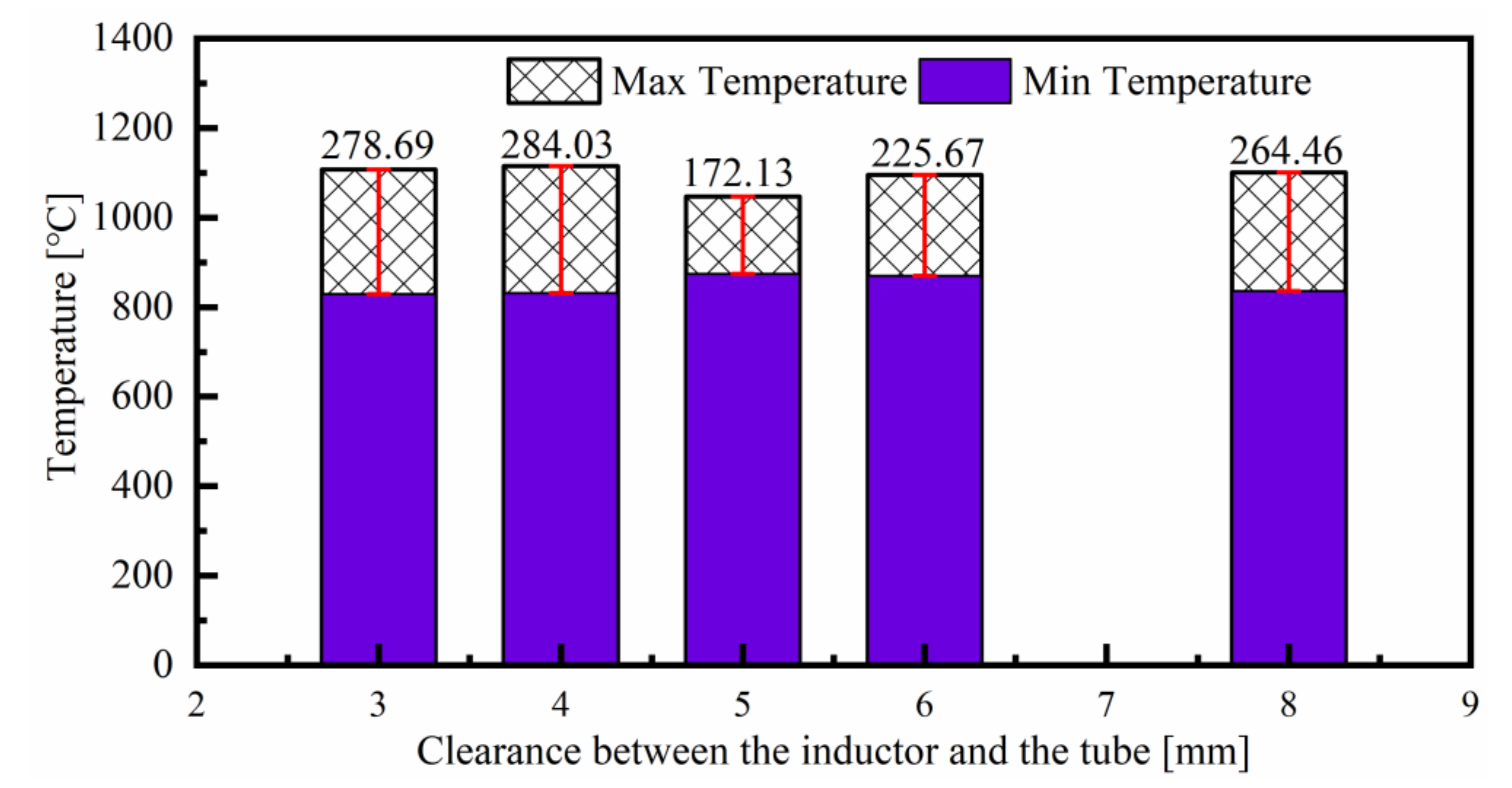
5.2. Effects of the Clearance Between the Inductor and Tube on the Temperature Distribution

Figure 15 presents the time taken for the average temperature of the middle section of the TWRST to reach 942 ± 0.1 °C under different clearances between the inductor and the tube (input current: 4000 A; current frequency: 14,000 Hz; inductor with structure c with a width of 10 mm). The figure reveals that it took 1.94 s for the middle section of the TWRST to reach an average temperature of 941.93 °C when the clearance between the inductor and the TWRST was 4 mm, while it took 1.85 s for the middle section of the TWRST to reach an average temperature of 941.92 °C when the clearance between the inductor and the TWRST was 5 mm. The reason for this is that the temperature difference of 172.13 °C with the clearance of 5 mm was much less than the temperature difference of 284.03 °C with the clearance of 4 mm (Figure 16).
The air gap mainly affects the proximity effect of induction heating; the smaller the air gap, the stronger the proximity effect. Moreover, the induced current is more concentrated on the outer wall of the tube; thus, its local Joule heat is greater, which causes the temperature of the outer wall of the tube to rise faster. While the time required to reach a certain average temperature in the middle section of the inductor was found to increase with the increase in the clearance between the inductor and the TWRST, the temperature difference under different clearances must also be considered.
When the clearance between the inductor and the TWRST is too large or too small, the cross-sectional temperature difference of the TWRST will increase, which will affect the forming quality and limit. It is reasonable to choose a clearance of 5 mm between the inductor and the TWRST. However, in the bending process, and the TWRST scratched the inductor on the inner side of the bend; thus, the clearance between the inductor and the TWRST was adjusted to 8 mm.

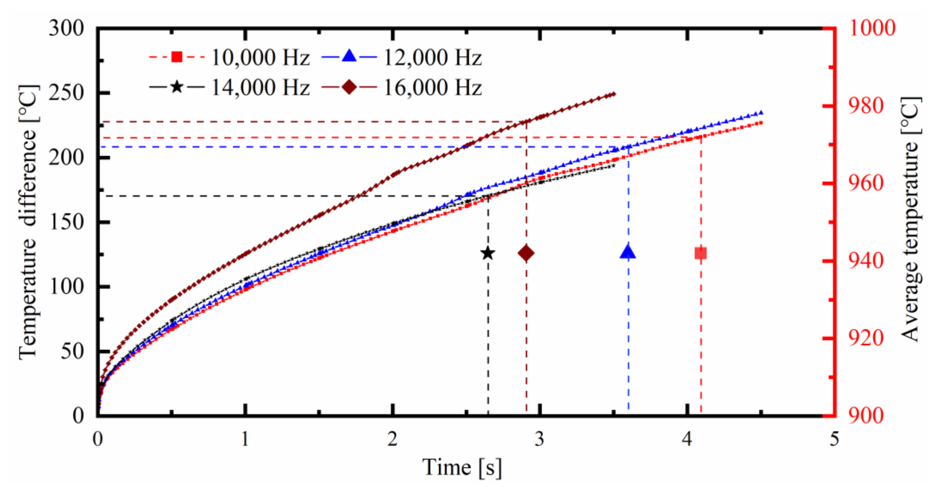
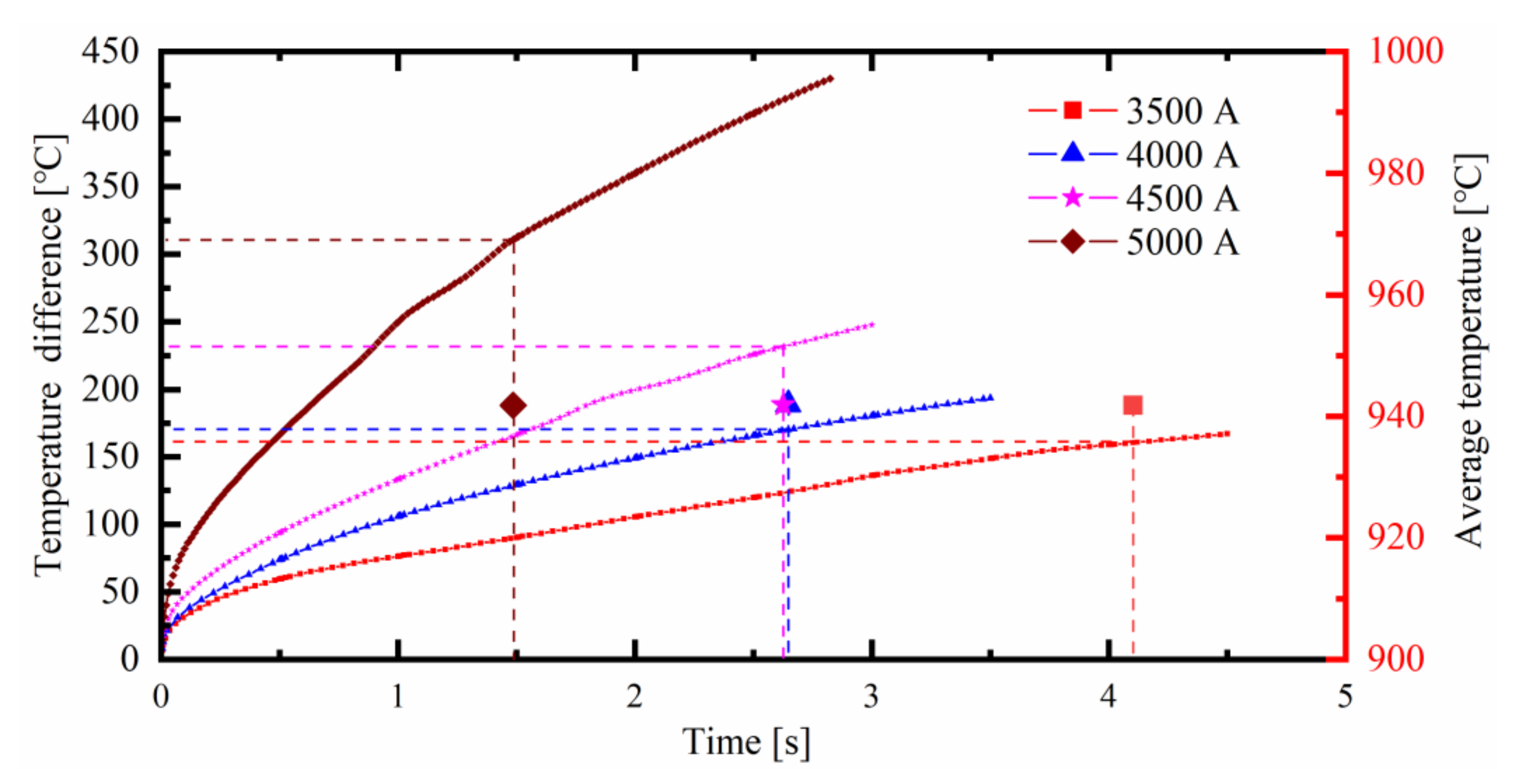
5.3. Effects of the Current Intensity and Frequency on the Temperature Distribution

Changing the current intensity and frequency will affect the temperature distribution of the TWRST. When an alternating current is applied to the inductor, an eddy current is generated on the surface of the TWRST due to the electromagnetic induction. According to the skin effect, when there is an alternating current or an alternating magnetic field in a conductor, the current will be unevenly distributed inside the conductor and the current is concentrated in a thin layer on the outer surface of the conductor, which is called the penetration depth. To ensure that the TWRST can be fully heated, the penetration depth must be greater than the wall thickness of the TWRST. The current frequency is calculated as δ tube   =   503 , 000 ρ / ( μ r f ) (where the relative permeability μr = 1, resistivity ρ tube   =   1.98   ×   10 7   Ω m , and the wall thickness of the B1500HS TWRST δ tube   =   1.5   mm ), and the current frequency should be less than 22,265 Hz to ensure that the penetration depth is greater than the wall thickness of the TWRST.
Figure 17 presents the temperature difference and average temperature 942 ± 0.1 °C of the TWRST with different current frequencies (input current: 4000 A; clearance between the inductor and the TWRST: 8 mm; inductor with structure c with a width of 10 mm). The figure reveals that the temperature difference increased with the increase in the heating time; when the middle section of the TWRST reached the average temperature of 942 ± 0.1 °C with the current frequencies of 10,000, 12,000 and 16,000 Hz, the required heating time was 4.09, 3.6 and 2.91 s, respectively. There was a significant difference in heating efficiency, and the temperature difference is less than 20 °C. Therefore, the heating efficiency can be improved by increasing the current frequency within the allowable range of the process conditions. When the middle section of the TWRST reached the average temperature of 942 ± 0.1 °C with the current frequency of 14,000 Hz, the heating time and temperature difference were the least.
Figure 18 presents the temperature difference and average temperature 942 ± 0.1 °C of the rectangular steel tube with different currents (current frequency: 14,000 Hz; clearance between the inductor and the TWRST: 8 mm; inductor with structure c with a width of 10 mm). The figure reveals the following. (1) The temperature difference increased with the increase in the heating time. (2) The temperature difference increased with the increase in heating current at the same heating time point. (3) When the middle section of the TWRST reached the average temperature of 942 ± 0.1 °C with the input current of 4000 and 4500 A, the required heating time was 2.65 and 2.63 s, respectively, and the heating efficiency was almost the same. Additionally, the temperature differences were 170.4 and 231.56 °C, respectively, exhibiting a difference of 61.15 °C, which is not conducive to the quality control of the hot bending forming. Therefore, increasing the input current may not improve the heating efficiency, but rather will increase the temperature difference and reduce the forming quality of the tube. (4) When the middle section of the TWRST reached the average temperature of 942 ± 0.1 °C with the input currents of 3500 and 5000 A, the required heating time was 4.1 and 1.49 s, respectively, and the heating efficiency differed greatly. If the input current is too small, the steel tube cannot be heated to the target temperature in the heating zone when it is fed at a low rate. If the current is too large, the steel tube will exhibit a large circumferential temperature difference. When the input current was 5000 A, the temperature difference in the middle section of the TWRST was as high as 310.9 °C, which would cause a large difference in the circumferential strength distribution of the bent tube. Therefore, compared with improving the heating efficiency by increasing the current, it is more reasonable to improve the heating efficiency by reducing the clearance between the inductor and rectangular steel tube.

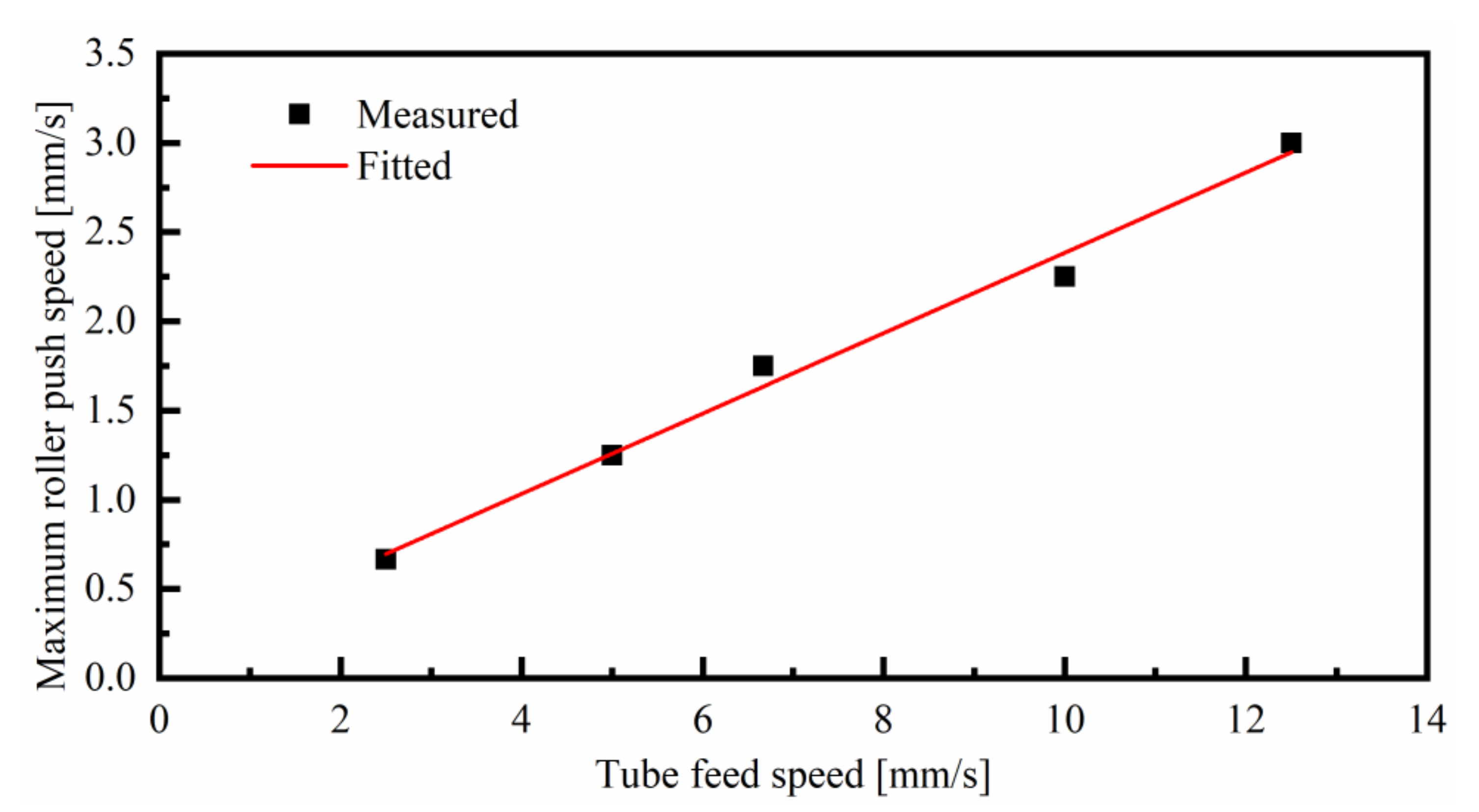
5.4. Effects of the Feed Rate of the Rectangular Steel Tube and the Push Speed of the Bending Roller on the Bending Forming Quality

Under the conditions of the VC-LIHBF process, the TWRST is formed via the interaction of the roll-bending device and the pusher; thus, the feed rate of the TWRST and push speed of the bending roller are both important parameters that affect the forming quality. The hot deformation zone is affected not only by the bending moment, but also by the axial thrust. This greatly reduces the elongation deformation on the outer side of the bending tube, and increases the compression deformation on the inner side of the bending tube. Therefore, there are two forming quality problems in the LIHBF process of bending a B1500HS TWRST, namely wrinkling and cross-sectional distortion.
Figure 19 presents the distribution of circumferential stress with different feed rates of the tube. The figure reveals that concavity occurred on the inner side of the TWRST when the push speed of the bending roller was 10 mm/s. The reason for this is that the push speed of the bending roller is higher at the initial stage of bending, and the LIHBF zone was subjected to greater circumferential stress, and the flow of the material lagged behind the speed of the bending tube. If the push speed is too high, the bent tube will appear similar to a “gooseneck” and subsequent bending forming may not even be possible due to the severe accumulation of material (Figure 20).
The history curves of the maximum tangential compressive and circumferential stresses with different tube feed rates are presented in Figure 21. They reveal that the tangential compressive stress was the largest when the feed rate of the tube was 10 mm/s, thus its wrinkling tendency was higher than that when the feed rate of the tube was 5 mm/s or 2.5 mm/s. Additionally, it was found that the minimum bending radius without wrinkling increased with the increase in the feed rate of the TWRST (Figure 22a). The results presented in Figure 21b show that the circumferential stress was the highest when the feed rate of the tube was 2.5 mm/s, thus the cross-sectional distortion rate was higher than that when the feed rate of the tube was 10 mm/s or 5 mm/s (Figure 22b).
The data in Figure 23 show that the allowable maximum push feed of the bending roller Vroller will increase with the increase in the feed rate of the tube Vtube. The relationship between Vtube and Vroller was found to be almost linear, and the fitting coefficient was 0.9855. The quality of the bent tube can be improved when Vroller/Vtube < 0.225.
In summary, in the LIHBF zone, the temperature distribution is relatively uniform and the tangential compressive stress is relatively small when the feed rate of the TWRST is small, and a bent tube with a small radius can be obtained. However, it is subject to larger circumferential stress in the LIHBF zone, which causes greater cross-sectional deformation. The lower the feed rate of the TWRST, the longer it takes to pass the inductor, and the more serious the surface oxidation of the tube. Conversely, the higher the feed rate of the TWRST, the shorter the induction heating time, the more uneven the temperature distribution and deformation of the LIHBF zone, the larger the tangential compressive stress, the higher the wrinkling tendency and the smaller the forming limit. Additionally, the lower the push speed of the bending roller, the longer the variable curvature arc length of the bent tube, and the lower the production efficiency. Therefore, it is extremely important to select the appropriate feed rate of the TWRST and push speed of the bending roller in the LIHBF process.

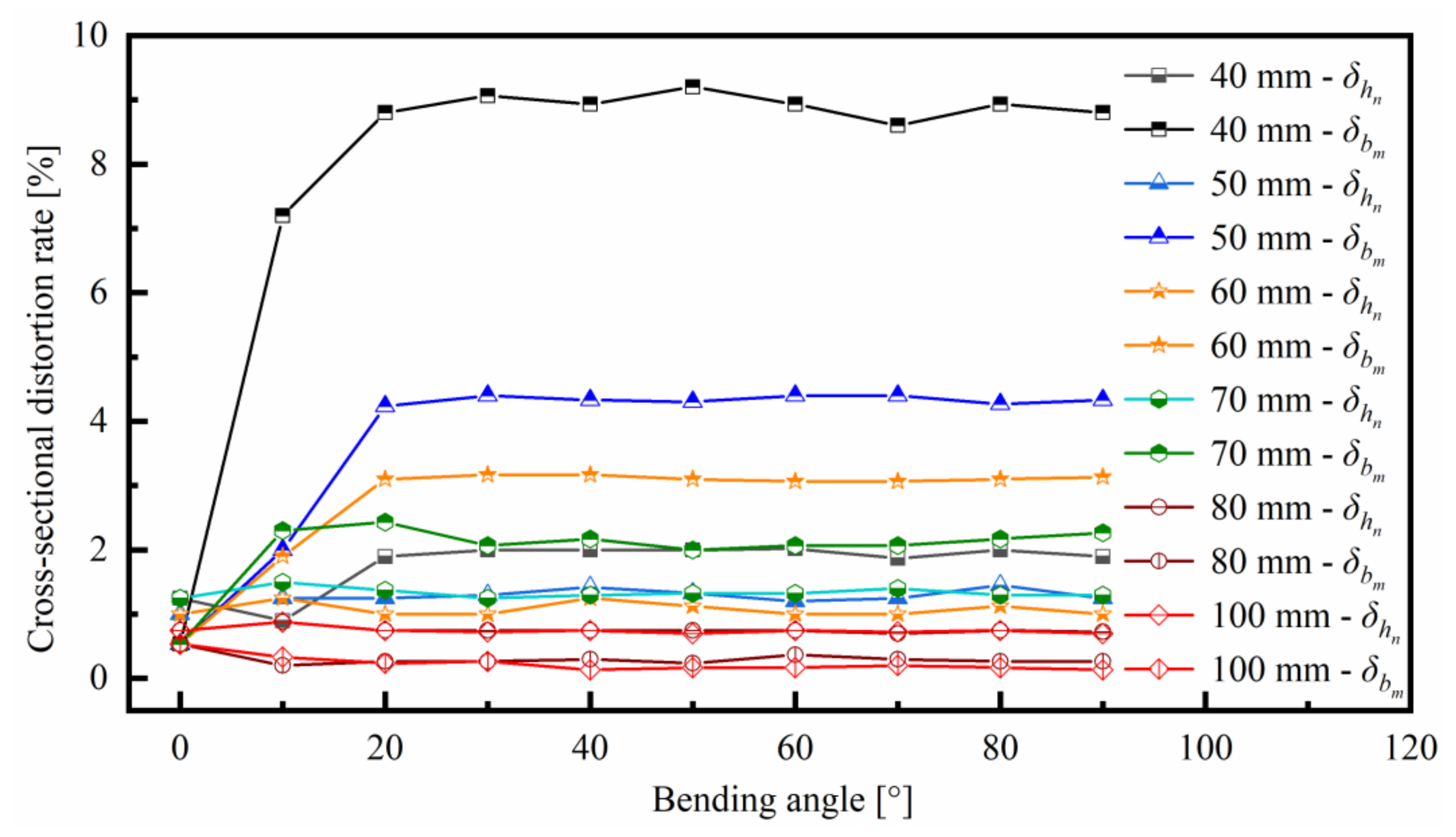
5.5. Effects of the Distance between the Inductor and the Bending Roller on the Bending Forming Quality

Different distance between the inductor and the bending roller will affect the stress distribution and cooling rate of the TWRST in the LIHBF process. Therefore, the distance between the inductor and the bending roller is an important parameter that affects the forming quality.
The results presented in Figure 22a show that concavity occurred on the inner and outer sides of the bent tube when the distance between the inductor and the bending roller was less than 40 mm, and the concavity was more serious with the decrease in the bending radius. The maximum cross-sectional distortion rate of the bent tube reached 31.57% when the distance between the inductor and the bending roller was 35 mm and the radius of the bent tube was 93 mm. Because the bending roller was close to the bending forming area, the bending tube was subjected to a large stress, and the cooling water hit the bending roller and flowed back to the surface of the TWRST, so that the maximum cooling rate is greater than 360 °C/s, resulting in the excessive residual stress of the bent tube and the occurrence of delayed cracks. Concavity occurred on the inner and outer sides of the bent tube when the distance between the inductor and the bending roller ranged between 40 and 65 mm, but it was reduced with the increase in the distance between the inductor and the bending roller. When the bending roller gradually moved away from the LIHBF area, the stress on the bent tube was reduced and the cooling rate was not affected; thus, there were no delayed cracks. Only a slight concavity occurred on the inner side of the bent tube when the distance between the inductor and the bending roller was greater than 65 mm.
The history curves of the maximum circumferential stress with different distances between the inductor and the bending roller are displayed in Figure 24. They reveal that the maximum circumferential stress in the LIHBF zone decreased and tended to be stable with the increase in the distance between the inductor and the bending roller. This caused a decrease in the cross-sectional deformation as the distance between the bending roller and the inductor increased during the LIHBF process of the TWRST (Figure 25).

6. Conclusions

The local-induction-heating bending forming (LIHBF) process of a B1500HS thin-walled rectangular steel tube (TWRST) was investigated by the finite element analysis and bending forming experiments. The results of this study can be summarized as follows:
(1)
The temperature distribution was calculated and the structural and geometric parameters of the inductor were determined by three-dimensional electromagnetic and heat transfer analyses. The air gap, namely the clearance between the inductor and the TWRST, has a major effect on the proximity effect of the induction heating; the smaller the air gap, the stronger the proximity effect, and the higher the heating efficiency. It is more reasonable to improve the heating efficiency by reducing the clearance between the inductor and the TWRST than by increasing the input current.
(2)
A suitable feed rate of the TWRST and the push speed of the bending roller, and the distance between the inductor and the tube are all important for the improvement of the cross-sectional distortion and the forming limit of the TWRST. The good quality of a bent tube with a section size of 30 mm (Width) × 40 mm (Height) × 1.5 mm (Thickness) can be achieved when Vroller/Vtube < 0.225.
(3)
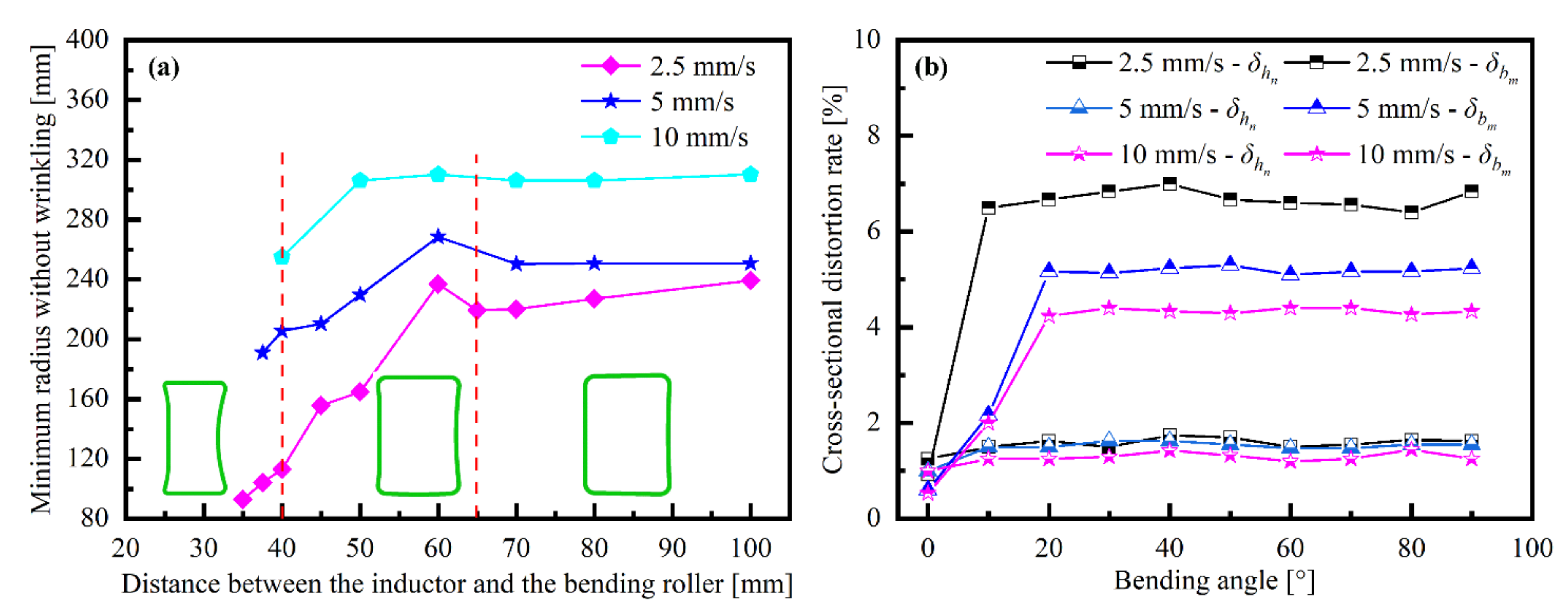
The cross-sectional distortion increases with the decrease in the distance between the inductor and the bending roller and the feed rate of the TWRST. The minimum radius of the bent TWRST without wrinkling increases with the increase in the feed rate of the TWRST.
(4)
The influence mechanisms of process parameters on temperature difference, such as the current intensity and frequency, and distance between the inductor and the tube, require further study.

Author Contributions

T.C., C.L. and H.F. conceived and designed the study; T.C. performed the experiments and provided figures and tables; T.C., C.L. and W.Y. analyzed the data and edited the manuscript. C.L., W.Y., H.F. and Z.X. reviewed and improved the manuscript. All authors have read and agreed to the published version of the manuscript.

Funding

The work was support by Project of Laboratory of Lightweight Structure & Advanced Forming Technology, Harbin Institute of Technology, China (No.MH20170272 and No.MH20190289).

Institutional Review Board Statement

Not applicable.

Informed Consent Statement

Not applicable.

Data Availability Statement

The authors confirm that the data supporting the findings of this study are available within the article.

Conflicts of Interest

The authors declare that they have no conflicts of interest.

References

  1. Hu, Z. Elasto-plastic solutions for spring-back angle of pipe bending using local induction heating. J. Mater. Process. Tech. 2000, 102, 103–108. [Google Scholar] [CrossRef]
  2. Lee, H.W.; Bae, J.H.; Kim, M.S.; Kim, C. Optimum design of pipe bending based on high-frequency induction heating using dynamic reverse moment. Int. J. Precis. Eng. Man. 2011, 12, 1051–1058. [Google Scholar] [CrossRef]
  3. Uematsu, K.; Shimada, N.; Tomizawa, A.; Mori, H. Development of three-dimensional hot bending and direct quench using robot. In Proceedings of the International Conference on Intelligent Informatics and Biomedical Sciences (ICIIBMS), Okinawa, Japan, 28–30 November 2015; pp. 165–171. [Google Scholar]
  4. Wang, Z.T.; Hu, Z. Theory of pipe-bending to a small bend radius using induction heating. J. Mater. Process. Tech. 1990, 21, 275–284. [Google Scholar]
  5. Hu, Z.; Li, J.Q. Computer simulation of pipe-bending processes with small bending radius using local induction heating. J. Mater. Process. Tech. 1999, 91, 75–79. [Google Scholar] [CrossRef]
  6. Li, X.; Wang, M.; Du, F.; Xu, Z. FEM simulation of large diameter pipe bending using local heating. J. Iron Steel Res. Int. 2006, 13, 25–29. [Google Scholar] [CrossRef]
  7. Batista, G.Z.; Hippert, J.E.; Naschpitz, L.; De, B.I.S. Induction hot bending and heat treatment of 20″ API 5L X80 pipe. In Proceedings of the International Pipeline Conference, Calgary, AB, Canada, 25–29 September 2006; pp. 89–98. [Google Scholar]
  8. Kubota, H.; Tomizawa, A.; Yamamoto, K.; Okada, N.; Hama, T.; Takuda, H. Finite element analysis of three-dimensional hot bending and direct quench process considering phase transformation and temperature distribution by induction heating. ISIJ Int. 2014, 54, 1856–1865. [Google Scholar] [CrossRef] [Green Version]
  9. Guo, X.; Jin, K.; Wang, H.; Pei, W.; Ma, F.; Tao, J.; Kim, N. Numerical simulations and experiments on fabricating bend pipes by push bending with local induction-heating process. Int. J. Adv. Manuf. Technol. 2015, 84, 2689–2695. [Google Scholar] [CrossRef]
  10. Ma, F.; Jin, K.; Wang, H.; Pei, W.J.; Tang, X.B.; Tao, J.; Guo, X.Z. Flow stress analysis and hot bending of P11 alloy steel. J. Mater. Eng. Perform. 2016, 25, 3725–3736. [Google Scholar] [CrossRef]
  11. Kathayat, T.S.; Goyal, R.K.; Hill, R.; Kyada, T. Optimization of pipe induction bending process parameters. In Proceedings of the ASME 2017 India Oil and Gas Pipeline Conference, Mumbai, India, 20–22 April 2017. [Google Scholar]
  12. Li, H.; Yang, H.; Zhan, M.; Sun, Z.C.; Gu, R.J. Role of mandrel in NC precision bending process of thin-walled tube. Int. J. Mach. Tools Manuf. 2007, 47, 1164–1175. [Google Scholar]
  13. Fang, J.; Lu, S.; Wang, K.; Xu, J.; Xu, X.; Yao, Z. Effect of mandrel on cross-section quality in numerical control bending process of stainless steel 2169 small diameter tube. Adv. Mater. Sci. Eng. 2013, 2013, 1–9. [Google Scholar] [CrossRef] [Green Version]
  14. Wang, Y.B. Research on Controlling Microstructure and Property of High-Strength Steel Rectangular Tube in Induction Hardening. Master’s Thesis, Harbin Institute of Technology, Harbin, China, 2015. [Google Scholar]
  15. Li, H.P.; He, L.F.; Zhao, G.Q.; Zhang, L. Constitutive relationships of hot stamping boron steel B1500HS based on the modified Arrhenius and Johnson–Cook model. Mater. Sci. Eng. A 2013, 580, 330–348. [Google Scholar] [CrossRef]
  16. Jonas, J.J.; Sellars, C.M.; Tegart, W.J.M. Strength and structure under hot-working conditions. Metall. Rev. 1969, 14, 1–24. [Google Scholar] [CrossRef]
  17. Pu, E.; Zheng, W.; Xiang, J.; Song, Z.; Li, J. Hot deformation characteristic and processing map of superaustenitic stainless steel S32654. Mater. Sci. Eng. A 2014, 598, 174–182. [Google Scholar] [CrossRef]
  18. Li, M.Y.; Dan, Y.C.; Yao, D.; Guan, Y.P.; Yang, L. Constitutive model and flow behavior of B1500HS High-strength steel during the hot deformation process. Metals 2019, 10, 64. [Google Scholar] [CrossRef] [Green Version]
  19. Xiao, Y.H.; Guo, C. Constitutive modelling for high temperature behavior of 1Cr12Ni3Mo2VNbN martensitic steel. Mater. Sci. Eng. A 2011, 528, 5081–5087. [Google Scholar] [CrossRef]
  20. Wang, W.T.; Guo, X.Z.; Huang, B.; Tao, J.; Li, H.G.; Pei, W.J. The flow behaviors of CLAM steel at high temperature. Mater. Sci. Eng. A 2014, 599, 134–140. [Google Scholar] [CrossRef]
  21. Xia, Y.F.; Ji, S.; Zhang, Y.D.; Wu, D.S.; Quan, G.Z. Deformation behavior and dynamic recovery kinetics of ultrahigh strength steel br1500hs at elevated temperature. High. Temp. Mater. Proc. 2014, 34, 503–513. [Google Scholar] [CrossRef]
  22. Xing, Z.W.; Cui, J.J.; Liu, H.S.; Li, C.F. Numerical and experimental investigation into hot stamping of high strength steel sheet for auto b pillar reinforced panel. Adv. Mat. Res. 2020, 129–131, 322–327. [Google Scholar] [CrossRef]
  23. Asao, H.; Okada, K.; Watanabe, M.; Yonemura, H.; Matsumoto, T.; Umehara, N. Analysis in workability of pipe bending using high frequency induction heating. In Proceedings of the Twenty-Fourth International Machine Tool design and Research Conference, Manchester, UK, 31 August–1 September 1983; pp. 97–104. [Google Scholar]
Figure 1. Schematic of push bending with the local-induction-heating bending forming process.
Metals 11 00132 g001
Figure 2. Procedure of local-induction-heating bending forming analysis.
Metals 11 00132 g002
Figure 3. Magnetization curves of B1500HS steel at different temperatures.
Metals 11 00132 g003
Figure 4. Hot compression simulation: (a) Gleeble-1500D system; (b) Hot compression simulation specimens.
Metals 11 00132 g004
Figure 5. The true stress–strain curves of B1500HS steel under the different deformation conditions: (a) 650 °C; (b) 750 °C; (c) 850 °C; (d) 900 °C; (e) 950 °C; (f) 1000 °C.
Metals 11 00132 g005
Figure 6. Local-induction-heating bending equipment.
Metals 11 00132 g006
Figure 7. Distribution of the measured sections.
Metals 11 00132 g007
Figure 8. Geometric parameters of each measured section.
Metals 11 00132 g008
Figure 9. Comparison between the experimental and simulated results (feed rate of the tube: 10 mm/s; push speed of the bending roller: 1.5 mm/s; distance between the inductor and the bending roller: 50 mm): (a) cross-sectional distortion rate; (b) wall thickness.
Metals 11 00132 g009
Figure 10. Different inductor structures: (a) The current input and output terminals are located on the short side of the inductor; (b) The current input and output terminals are located on the long side of the inductor; (c) The current input and output terminals are located on the diagonal of the inductor (non-uniform clearance between the inductor and the rectangular tube); (d) The current input and output terminals are located on the diagonal of the inductor (uniform clearance between the inductor and the rectangular tube).
Metals 11 00132 g010
Figure 11. The temperature distributions of a rectangular steel tube based on different inductor structures: (a) the inductor with the structure a; (b) the inductor with the structure b; (c) the inductor with the structure c; (d) the inductor with the structure d.
Metals 11 00132 g011
Figure 12. The temperature distribution in the middle section of the rectangular steel tube: (a) the inductor with the structure c; (b) the inductor with the structure d.
Metals 11 00132 g012
Figure 13. The temperature distribution of a rectangular steel tube with different inductor widths: (a) 5 mm; (b) 10 mm; (c) 15 mm; (d) 20 mm.
Metals 11 00132 g013
Figure 14. The temperature difference of a rectangular steel tube based on inductor with different widths.
Metals 11 00132 g014
Figure 15. The time taken for the average temperature to reach 942 ± 0.1 °C under different clearances between the inductor and the tube.
Metals 11 00132 g015
Figure 16. The temperature difference under different clearances between the inductor and the tube.
Metals 11 00132 g016
Figure 17. The temperature difference and average temperature of 942 ± 0.1 °C with different current frequencies.
Metals 11 00132 g017
Figure 18. The temperature difference and average temperature 942 ± 0.1 °C with different input currents.
Metals 11 00132 g018
Figure 19. Distribution of the circumferential stress with different push speeds of the bending roller (distance between the inductor and the bending roller: 50 mm): (a) 1.25 mm/s; (b) 10 mm/s.
Metals 11 00132 g019
Figure 20. The bent tube under a higher push speed of the bending roller.
Metals 11 00132 g020
Figure 21. History curves of the maximum stress with different feed rates of the tube (distance between the inductor and bending roller: 50 mm): (a) The maximum tangential compressive stress; (b) the maximum circumferential stress.
Metals 11 00132 g021
Figure 22. Experimental results with different feed rates of the tube: (a) Minimum radius with different distances between the inductor and the bending roller; (b) Cross-sectional distortion rate at different bending angles (distance between the inductor and the bending roller: 50 mm).
Metals 11 00132 g022
Figure 23. The relationship between the maximum push speed of the bending roller and the feed rate of the tube.
Metals 11 00132 g023
Figure 24. History curves of the maximum circumferential stress with different distances between the inductor and the bending roller (feed rate of the tube: 10 mm/s).
Metals 11 00132 g024
Figure 25. Experimental results with difference distances between the inductor and the bending roller (feed rate of the tube: 10 mm/s).
Metals 11 00132 g025
Table 1. Chemical composition of B1500HS steel (wt.%).
CBMnCrAlSiSPTi
0.19–0.2550.0008–0.0051.1–1.40.15–0.350.02–0.06≤0.4≤0.015≤0.0250.02–0.05
Table 2. Thermophysical parameters of B1500HS steel.
Temperature (°C)20200400600850900950
Parameters
Thermal conductivity (W/(m·K))313440424343.545
Specific heat (J/kg·k)45046247563396910231062
Resistivity ( ×   1 0 6   Ω m )   [14]0.1980.3390.5410.791.1351.1621.196
Young’s modules (GPa)207180150110908985
Table 3. Experimental conditions.
ParameterSpecification
Inductor current frequency 14,000 HZ
Heating power25.48–72.45 KW
Clearance between the inductor and the tube8 mm
Angle between the jet holes and the axial direction50°
Rectangular tube material B1500HS
Rectangular tube section size30 mm (Width) × 40 mm (Height) × 1.5 mm (Thickness) with a 4-mm radius outer fillet
Feed rate of the TWRST2.5–12.5 mm/s
Push speed of the bending roller0.667–3 mm/s
Distance between the bending roller and the inductor35–100 mm
Bending angle90°
Publisher’s Note: MDPI stays neutral with regard to jurisdictional claims in published maps and institutional affiliations.

