Hybrid Self-Reacting Friction Stir Welding of AA 6061-T6 Aluminium Alloy with Cooling Assisted Approach


Abstract
:
1. Introduction
2. Materials and Methods
3. Results and Discussion
3.1. Thermal Cycles
3.2. Macrostructure of the Joint
3.3. Microstructure of the Joint
3.4. Tensile Properties
3.5. Microhardness of the Joint
3.6. Fractography
4. Conclusions
- (1)
- Coling systems S-RM, S-IM, and C-RJ resulted in a reduction of peak temperature by 11.39%, 15.71%, and 35.05% respectively compared to peak temperature during NAC.
- (2)
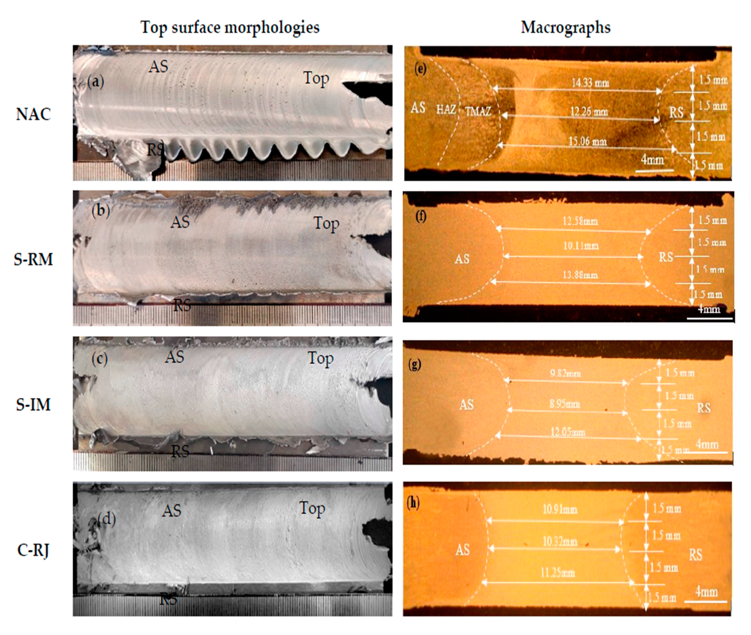
- The width of the top, middle, and bottom parts of WNZ are reduced in cooling assisted joints compared to the as-welded joint. The width of the bottom part was lower than the top part of WNZ in all the samples.
- (3)
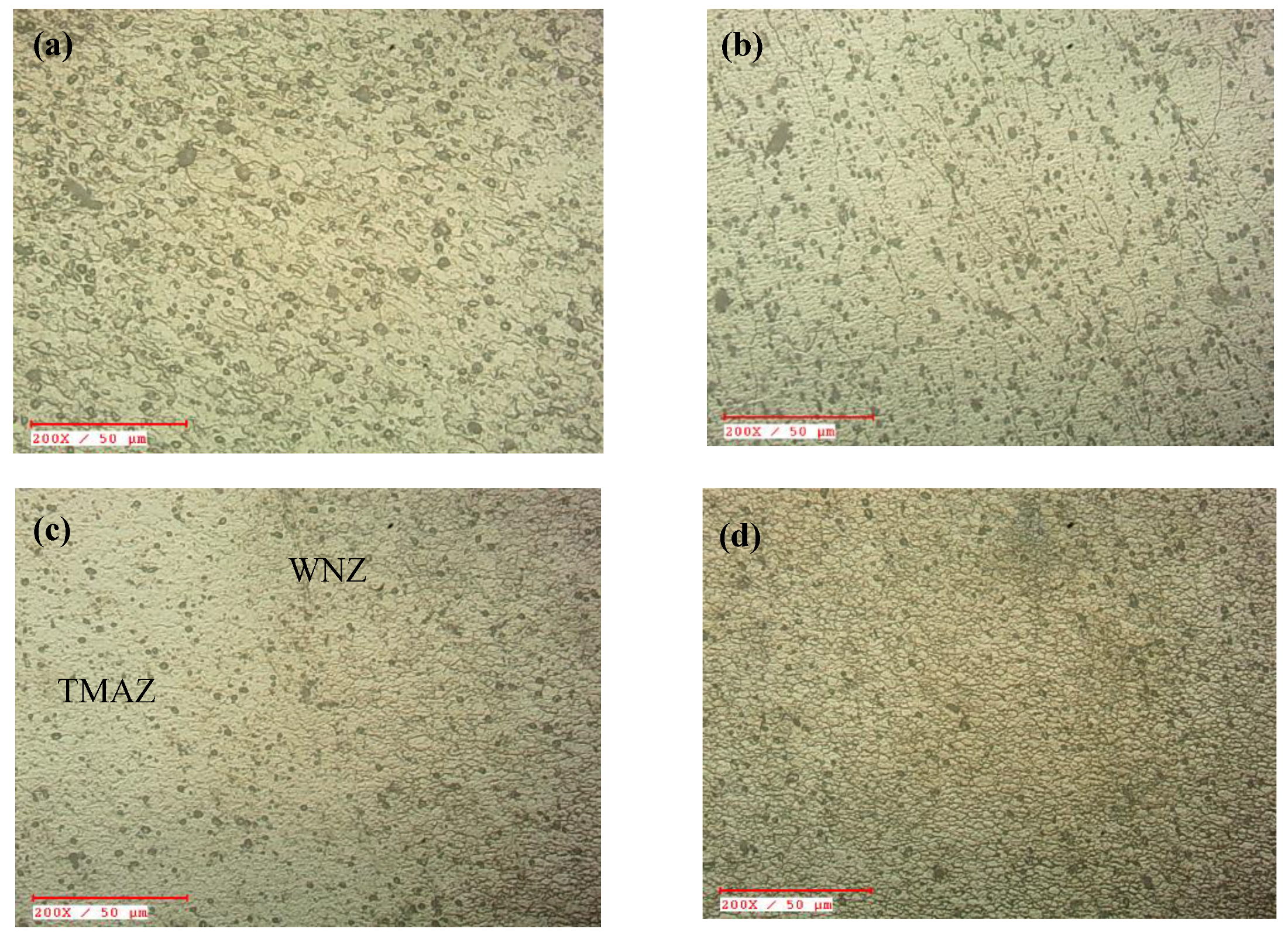
- SRFSW creates hourglass shape WNZ. The WNZ exhibited a fine and equiaxed microstructure for all the joints. The maximum and minimum average grain size of 18.68 µm and 10.69 µm was observed in NAC and C-RJ joints respectively. This concludes that the use of the water cooling media reduces grain size in WNZ.
- (4)
- The maximum tensile strength of 189.16 MPa which is 8.17% more than NAC was observed in C-RJ because of uniform thermal gradient and uniform cooling rate on both sides of the joint.
- (5)
- Symmetrical microhardness distribution is obtained in all the welds. The highest hardness value (~56.5 HV) in the lowest hardness zone was observed in C-RJ due to a significant reduction in grain size.
- (6)
- Natural air cooling assisted joints fractured in the heat-affected zone. However, the fracture location of S-RM and S-IM joints were shifted to the boundary of WNZ/TMAZ. The C-RJ joints failed from WNZ.
Author Contributions
Funding
Conflicts of Interest
Abbreviations
| AS | Advancing side |
| BTFSW | Bobbin tool friction stir welding |
| FSW | Friction stir welding |
| HAZ | Heat affected zone |
| LAZ | Lowest hardness zone |
| NAC | Natural air cooling |
| SRFSW | Self-reacting friction stir welding |
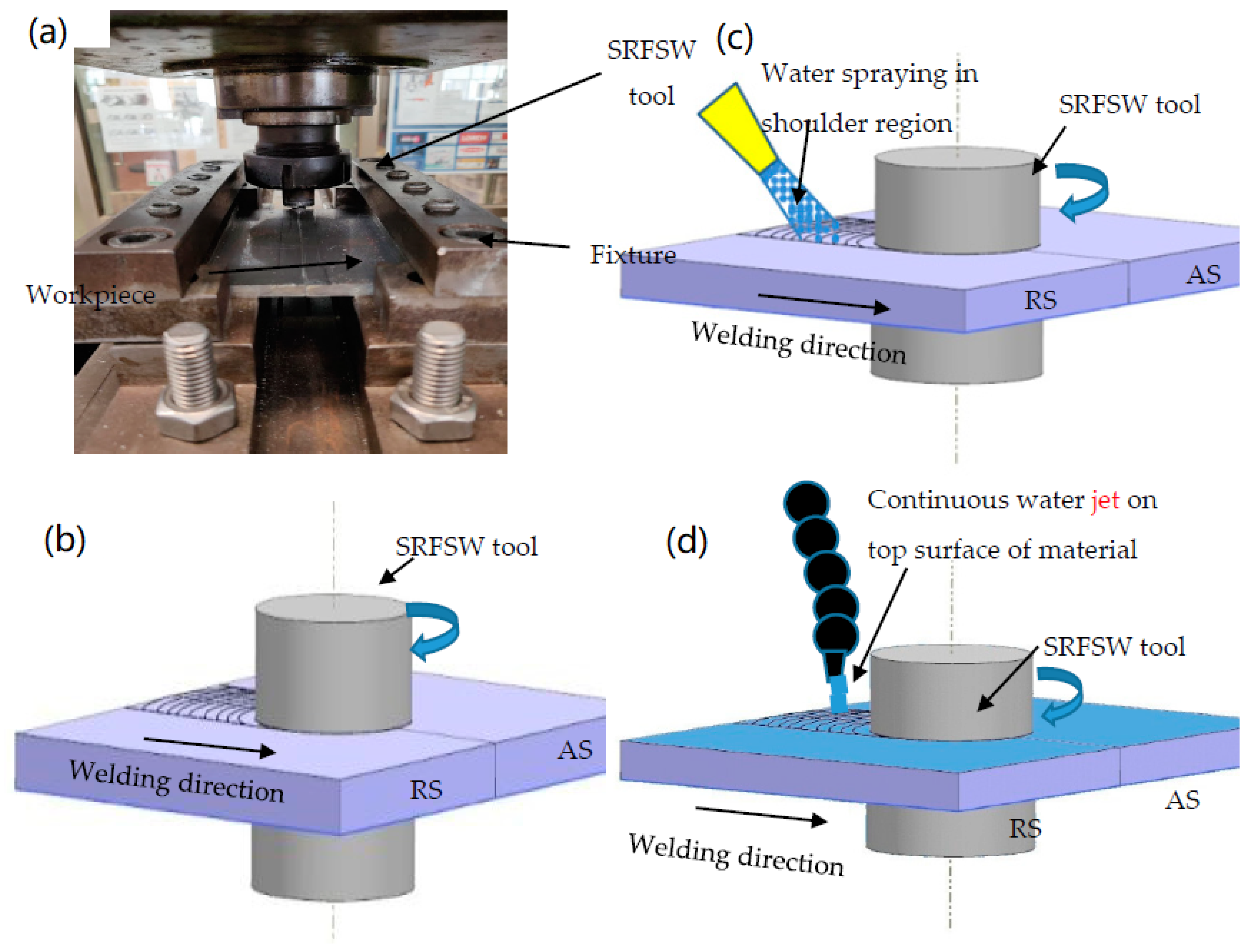
| S-RM | Spraying with room temperature water mist |
| S-IM | Spraying with ice water mist |
| TMAZ | Thermo-mechanically affected zone |
| C-RJ | Cooling with room temperature water jet |
| WNZ | Weld nugget zone |
References
- Zhou, L.; Li, G.H.; Liu, C.L.; Wang, J.; Huang, Y.X.; Feng, J.C.; Meng, F.X. Effect of Rotation Speed on Microstructure and Mechanical Properties of Self-Reacting Friction Stir Welded Al-Mg-Si alloy. Int. J. Adv. Manuf. Technol. 2017, 89, 3509–3516. [Google Scholar] [CrossRef]
- Cisko, A.; Jordon, J.; Amaro, R.; Allison, P.; Wlodarski, J.; McClelland, Z.; Garcia, L.; Rushing, T. A Parametric Investigation on Friction Stir Welding of Al-Li 2099. Mat Manuf Process. 2020, 1–8. [Google Scholar] [CrossRef]
- Li, Y.; Sun, D.; Gong, W. Effect of Tool Rotational Speed on the Microstructure and Mechanical Properties of Bobbin Tool Friction Stir Welded 6082-T6 Aluminum Alloy. Metals 2019, 9, 894. [Google Scholar] [CrossRef] [Green Version]
- Tamadon, A.; Pons, D.J.; Sued, K.; Clucas, D. Thermomechanical grain refinement in AA6082-T6 thin plates under Bobbin friction stir welding. Metals 2018, 8, 375. [Google Scholar] [CrossRef] [Green Version]
- Li, W.Y.; Fu, T.; Hütsch, L.; Hilgert, J.; Wang, F.F.; Dos Santos, J.F.; Huber, N. Effects of tool rotational and welding speed on microstructure and mechanical properties of bobbin-tool friction-stir welded Mg AZ31. Mater. Des. 2014, 64, 714–720. [Google Scholar] [CrossRef] [Green Version]
- Ding, R.J.; Schneider, J.; Walker, B. Advances in Solid State Joining of Haynes 230 High Temperature Alloy. In Proceedings of the 8th International Symposium on Friction Stir Welding, Timmendorfer Strand, Germany, 18–20 May 2010. [Google Scholar]
- Khorsid, A.; Moustafa, A.; Sabry, I. Investigation of the mechanical properties of Friction Stir Welded 6061 Al plates. Mater. Sci. Eng. 2001, 1–15. Available online: http://www.jeaconf.org/UploadedFiles/Document/97626981-7e64-4048-8a70-6a0e1f6f9847.pdf (accessed on 22 December 2020).
- Sahu, P.K.; Vasudevan, N.P.; Das, B.; Pal, S. Assessment of Self-Reacting Bobbin Tool Fiction Stir Welding for Joining AZ31 Magnesium Alloy at Inert Gas Environment. J. Magnes. Alloys 2019, 7, 661–671. [Google Scholar] [CrossRef]
- Fuse, K.; Badheka, V. Bobbin Tool Friction Stir Welding: A Review. Sci. Technol. Weld Join. 2019, 24, 277–304. [Google Scholar] [CrossRef]
- Verma, J.; Taiwade, R.V.; Reddy, C.; Khatirkar, R.K. Effect of Friction Stir Welding Process Parameters on Mg-AZ31B/Al-AA6061 Joints. Mat. Manuf. Process. 2018, 33, 308–314. [Google Scholar] [CrossRef]
- Verma, S.; Misra, J.P. Effect of Process Parameters on Temperature and Force Distribution during Friction Stir Welding of Armor-Marine Grade Aluminum Alloy. Proc. Inst. Mech. Eng. Part B 2020. [Google Scholar] [CrossRef]
- Verduzco Juárez, J.; Dominguez Almaraz, G.; García Hernández, R.; Villalón López, J. Effect of Modified Pin Profile and Process Parameters on the Friction Stir Welding of Aluminum Alloy 6061-T6. Adv. Mater. Sci. Eng. 2016. [Google Scholar] [CrossRef] [Green Version]
- Vignesh, R.V.; Padmanaban, R.; Arivarasu, M.; Thirumalini, S.; Gokulachandran, J.; Ram, M. Numerical Modelling of Thermal Phenomenon in Friction Stir Welding of Aluminum Plates. IOP Conf. Ser. 2016, 012208. [Google Scholar] [CrossRef] [Green Version]
- Shehabeldeen, T.A.; Abd Elaziz, M.; Elsheikh, A.H.; Hassan, O.F.; Yin, Y.; Ji, X.; Shen, X.; Zhou, J. A Novel Method for Predicting Tensile Strength of Friction Stir Welded AA6061 Aluminium Alloy Joints Based on Hybrid Random Vector Functional Link and Henry Gas Solubility Optimization. IEEE Access 2020, 8, 79896–79907. [Google Scholar] [CrossRef]
- Goyal, A.; Garg, R.K. Parametric optimization of friction stir welding process for marine grade aluminum alloy. Int. J. Struct. Integr. 2019, 10, 162–175. [Google Scholar] [CrossRef]
- Vijayan, S.; Raju, R.; Rao, S.K. Multiobjective optimization of friction stir welding process parameters on aluminum alloy AA 5083 using Taguchi-based grey relation analysis. Mater. Manuf. Process. 2010, 25, 1206–1212. [Google Scholar] [CrossRef]
- Mehta, K.P.; Carlone, P.; Astarita, A.; Scherillo, F.; Rubino, F.; Vora, P. Conventional and Cooling Assisted Friction Stir Welding of AA6061 and AZ31B alloys. Mater. Sci. Eng. A 2019, 759, 252–261. [Google Scholar] [CrossRef]
- Patel, P.; Rana, H.; Badheka, V.; Patel, V.; Li, W. Effect of Active Heating and Cooling on Microstructure and Mechanical Properties of Friction Stir–Welded Dissimilar Aluminium Alloy and Titanium Butt Joints. Weld World 2020, 64, 365–378. [Google Scholar] [CrossRef]
- Peng, G.; Yan, Q.; Hu, J.; Chen, P.; Chen, Z.; Zhang, T. Effect of Forced Air Cooling on the Microstructures, Tensile Strength, and Hardness Distribution of Dissimilar Friction Stir Welded AA5A06-AA6061 joints. Metals 2019, 9, 304. [Google Scholar] [CrossRef] [Green Version]
- Lin, H.; Wu, Y.; Liu, S.; Zhou, X. Effect of Cooling Conditions on Microstructure and Mechanical Properties of Friction Stir Welded 7055 Aluminium Alloy Joints. Mater. Charact. 2018, 141, 74–85. [Google Scholar] [CrossRef]
- Sinhmar, S.; Dwivedi, D. Enhancement of Mechanical Properties and Corrosion Resistance of Friction Stir Welded Joint of AA2014 Using Water Cooling. Mater. Sci. Eng. A 2017, 684, 413–422. [Google Scholar] [CrossRef]
- Fathi, J.; Ebrahimzadeh, P.; Farasati, R.; Teimouri, R. Friction Stir Welding of Aluminum 6061-T6 in Presence of Watercooling: Analyzing Mechanical Properties and Residual Stress Distribution. Int. J. Lightweight Mater. Manuf. 2019, 2, 107–115. [Google Scholar] [CrossRef]
- Liu, W.; Yan, Y.; Sun, T.; Wu, S.; Shen, Y. Influence of Cooling Water Temperature on ME20M Magnesium Alloy Submerged Friction Stir Welding: A Numerical and Experimental Study. Int. J. Adv. Manuf. Technol. 2019, 105, 5203–5215. [Google Scholar] [CrossRef]
- Jalili, N.; Tabrizi, H.B.; Hosseini, M.M. Experimental and Numerical Study of Simultaneous Cooling with CO2 Gas during Friction Stir Welding of Al-5052. J. Mater. Process. Technol. 2016, 237, 243–253. [Google Scholar] [CrossRef]
- Fujii, H.; Chung, Y.; Sun, Y. Friction Stir Welding of AISI 1080 Steel using Liquid CO2 for Enhanced Toughness and Ductility. Sci. Technol. Weld. Join. 2013, 18, 500–506. [Google Scholar] [CrossRef]
- Satyanarayana, M.; Kumar, A. Influence of Cooling Media in Achieving Grain Refinement of AA2014 alloy using Friction Stir Processing. Proc. Inst. Mech. Eng. Part C 2020. [Google Scholar] [CrossRef]
- Mehta, K.P.; Badheka, V.J. Hybrid Approaches of Assisted Heating and Cooling for Friction Stir Welding of Copper to Aluminum Joints. J. Mater. Process. Technol. 2017, 239, 336–345. [Google Scholar] [CrossRef]
- Zhou, L.; Li, G.H.; Zha, G.D.; Shu, F.Y.; Liu, H.J.; Feng, J.C. Effect of rotation speed on microstructure and mechanical properties of bobbin tool friction stir welded AZ61 magnesium alloy. Sci. Technol. Weld. Join. 2018, 23, 596–605. [Google Scholar] [CrossRef]
- Wang, F.F.; Li, W.Y.; Shen, J.; Hu, S.Y.; Dos Santos, J.F. Effect of tool rotational speed on the microstructure and mechanical properties of bobbin tool friction stir welding of Al–Li alloy. Mater. Des. 2015, 86, 933–940. [Google Scholar] [CrossRef] [Green Version]
- Li, G.; Zhou, L.; Luo, S.; Huang, Y.; Guo, N.; Zhao, H.; Song, X. Effect of self-reacting friction stir welding on microstructure and mechanical properties of Mg-Al-Zn alloy joints. J. Manuf. Processes. 2019, 37, 1–10. [Google Scholar] [CrossRef]
- Gaohui, L.I.; Li, Z.H.O.U.; Zhang, H.; Sanfeng, L.U.O.; Ning, G.U.O. Effects of traverse speed on weld formation, microstructure and mechanical properties of ZK60 Mg alloy joint by bobbin tool friction stir welding. Chin. J. Aeronaut. 2020. [Google Scholar] [CrossRef]
- Li, G.; Zhou, L.; Luo, S.; Dong, F.; Guo, N. Microstructure and mechanical properties of bobbin tool friction stir welded ZK60 magnesium alloy. Mater. Sci. Eng. A 2020, 776, 138953. [Google Scholar] [CrossRef]
- Li, G.H.; Zhou, L.; Luo, S.F.; Du, Z.Y.; Feng, J.C.; Meng, F.X. Microstructure and mechanical properties of self-reacting friction stir welded AA2219-T87 aluminium alloy. Sci. Technol. Weld. Join. 2020, 25, 142–149. [Google Scholar] [CrossRef]
- Mardalizadeh, M.; Khandaei, M.; Safarkhanian, M.A. Influence of travel speed on the microstructural evaluation and mechanical characteristics of bobbin tool friction stir-welded thick AA5456-H112 plates. J. Adhes. Sci. Technol. 2020, 1–20. [Google Scholar] [CrossRef]
- Zhao, Y.; Wang, C.; Dong, C. Microstructural Characteristics and Mechanical properties of Water Cooling Bobbin-Tool Friction Stir Welded 6063-T6 Aluminum Alloy. In MATEC Web of Conferences; EDP Sciences: Paris, France, 2018. [Google Scholar] [CrossRef] [Green Version]
- Belhocine, A.; Abdullah, O.I. Structural and contact analysis of disc brake assembly during single stop braking event. Trans. Indian Inst. Met. 2015, 68, 403–410. [Google Scholar] [CrossRef]
- Belhocine, A.; Bouchetara, M. Thermomechanical behaviour of dry contacts in disc brake rotor with a grey cast iron composition. Trans. Indian Inst. Met. 2012, 65, 231–238. [Google Scholar] [CrossRef]
- Wahid, M.A.; Siddiquee, A.N.; Khan, Z.A.; Sharma, N. Analysis of Cooling Media Effects on Microstructure and Mechanical Properties During FSW/UFSW of AA 6082-T6. Mater. Res. Express 2018, 5, 046512. [Google Scholar] [CrossRef]
- Hou, J.; Liu, H.; Zhao, Y. Influences of Rotation Speed on Microstructures and Mechanical Properties of 6061-T6 Aluminum Alloy Joints Fabricated by Self-Reacting Friction Stir Welding Tool. Int. J. Adv. Manuf. Technol. 2014, 73, 1073–1079. [Google Scholar] [CrossRef]


| Chemical Composition (wt %) | Mechanical Properties | |||||||||
|---|---|---|---|---|---|---|---|---|---|---|
| Si | Fe | Cu | Mn | Mg | Cr | Zn | Al | UTS (MPa) | Elongation (%) | Hardness (HV) |
| 0.457 | 0.553 | 0.173 | 0.106 | 0.937 | 0.266 | 0.010 | Bal | 282 | 21 | 80–90 |
| Cooling Type | Top (mm) | Middle (mm) | Bottom (mm) |
|---|---|---|---|
| NAC | 14.33 | 12.26 | 15.06 |
| S-IM | 12.58 | 10.11 | 13.88 |
| S-RM | 9.82 | 8.95 | 12.05 |
| C-RJ | 10.91 | 10.32 | 11.25 |
Publisher’s Note: MDPI stays neutral with regard to jurisdictional claims in published maps and institutional affiliations. |
© 2020 by the authors. Licensee MDPI, Basel, Switzerland. This article is an open access article distributed under the terms and conditions of the Creative Commons Attribution (CC BY) license (http://creativecommons.org/licenses/by/4.0/).
Share and Cite
Fuse, K.; Badheka, V. Hybrid Self-Reacting Friction Stir Welding of AA 6061-T6 Aluminium Alloy with Cooling Assisted Approach. Metals 2021, 11, 16. https://doi.org/10.3390/met11010016
Fuse K, Badheka V. Hybrid Self-Reacting Friction Stir Welding of AA 6061-T6 Aluminium Alloy with Cooling Assisted Approach. Metals. 2021; 11(1):16. https://doi.org/10.3390/met11010016
Chicago/Turabian StyleFuse, Kishan, and Vishvesh Badheka. 2021. "Hybrid Self-Reacting Friction Stir Welding of AA 6061-T6 Aluminium Alloy with Cooling Assisted Approach" Metals 11, no. 1: 16. https://doi.org/10.3390/met11010016