Article

Fatigue Crack Initiation and Propagation at High Temperature of New-Generation Bearing Steel

1
Faculty of Materials Science and Engineering, Kunming University of Science and Technology, Kunming 650093, China
2
Research Institute of Special Steels, Central Iron and Steel Research Institute, Beijing 100081, China
*
Author to whom correspondence should be addressed.
Metals 2021, 11(1), 25; https://doi.org/10.3390/met11010025
Submission received: 1 December 2020 / Revised: 16 December 2020 / Accepted: 21 December 2020 / Published: 25 December 2020
(This article belongs to the Special Issue Fatigue Cracks in Steel)

Abstract

:
The new generation of bearing steel has good comprehensive properties, which can satisfy most of the requirements of bearing steel in a complex environment. In the presented work, fatigue properties of 15Cr14Co12Mo5Ni2 bearing steel have been investigated by means of rotating bending fatigue tests on smooth bar specimens after carburization and heat treatment. Optical microscope, scanning electron microscopy, electron backscatter diffraction, and Image-Pro Plus software were used to analyze the fracture, microstructure, and carbides. The results suggest that the fatigue strength at room temperature and 500 °C is 1027 MPa and 585 MPa, respectively. Scanning electron micrographic observations on the fracture surface of the fatigue specimens at 500 °C show that fatigue cracks usually initiate from voids in the carburized case and oxide layer on the surface of steel. The failure mode in the carburized case is a quasi-cleavage fracture, and with the increase of crack propagation depth, the failure mode gradually changes to fatigue and creep-fatigue interaction. With the increase of the distance from the surface, the size of the martensite block decreases and the fracture surface shows great fluctuation.

1. Introduction

High-end bearings in aerospace, high-speed rail, and other fields not only need to have high hardness, corrosion resistance, high strength, good toughness, and other properties, but need to have high fatigue performance in high-temperature environments. However, the traditional bearing materials can only satisfy the performance requirements of a certain aspect, but do not have a good comprehensive performance. 15Cr14Co12Mo5Ni2 bearing steel (CN 108,118,260 A) is designed with a carbide strengthening mechanism by controlling the Cr-Mo ratio and adding a certain amount of carbide forming elements on the basis of ensuring corrosion resistance. Due to the addition of a large amount of Co element in steel, there are dispersed fine carbides in the matrix, so that the steel has high strength and toughness at the same time, becoming the most potential new generation bearing steel.
15Cr14Co12Mo5Ni2 bearing steel is a low-carbon high-alloy steel and has high surface hardness after carburizing. A large number of studies have shown that surface carburizing treatment can significantly improve the fatigue performance of steel [1,2]. After surface carburizing, the fatigue strength of 15Cr14Co12Mo5Ni2 bearing steel can reach 1016 MPa at room temperature [3]. The main failure causes were inclusions and carbides in the carburized case. During the carburizing process, the residual compressive stress had been introduced in the carburized case, effectively preventing the initiation of crack and reducing the propagation speed of crack. Nevertheless, in the case of stress concentration, the crack was easily initiated from the edge of the carbides in the carburized case and propagated along the carbides and grain boundaries where the bonding strength was weak [3]. Compared with the fatigue behavior at room temperature, the fatigue behavior of 15Cr14Co12Mo5Ni2 bearing steel at high temperature, which is the result of the interaction of fatigue and creep under the action of thermo-mechanical coupling, is more complex [4]. 15Cr14Co12Mo5Ni2 bearing steel undergoes a deformation process of shear deformation—fragmentation—rearrangement of martensite at high temperature. At this time, the dislocation density decreased and the carbides coarsen [5]. In a high-temperature environment, the surface of the specimen is easily oxidized, which promotes the initiation and propagation of cracking [6], thus reducing the fatigue performance of the steel. The decreasing degree of fatigue property of steel increases with the increase of cycle time.
Geng et al. [7] studied the rotational bending fatigue tests of 15Cr14Co12Mo5Ni2 bearing steel at room temperature, 300 °C, and 500 °C. The results show that the fatigue strength of the steel decreased with the increase of the test temperature. At room temperature, the surface defect was the crack initiation under the action of stress concentration. When the temperature rose to 500 °C, persistent slip bands were found at the crack initiation source. With an increase of temperature, the matrix hardness of steel decreased, and the persistent slip bands tended to appear under the action of long-time alternating stress. Under the action of thermo-mechanical coupling, the carbides nucleate along the dislocation line and grow. The interaction between the carbides and dislocation in the persistent slip bands resulted in microcrack at the edge of the carbides, and extended along the carbides. Zhang and Lin et al. [8,9] studied the high-temperature rotational bending fatigue performance of 40Cr15Mo2VN high-nitrogen stainless steel. It was found that the safe fatigue limit strength values at 200 °C was 17% lower than that at room temperature. The main reason was that the threshold value of fatigue stress intensity factor Δ K t h was reduced at 200 °C, leading to a decrease in the size of the critical non-metallic inclusion at the beginning of fatigue crack initiation. At 200 °C, the interaction of small cracks near the crack initiation source in the surface initiation cracks increased the stress intensity factor K I and accelerated the initial surface crack propagation. The safe fatigue limit at 300 °C was 8.5% lower than that at 400 °C. Due to the higher degree of creep void aggregation at 300 °C, it was easier to connect voids to microcracks and this led to greater fatigue failure than that at 400 °C. Li et al. [10] studied the effects of different temperatures on the fatigue resistance and crack growth rate of TC17, and the results show that the initiation of cracks account for the majority of the fatigue life, and high temperature not only promoted the crack initiation but also promoted the crack propagation.
Available results in the literature about the fatigue performance at high temperature mainly focus on superalloy materials. However, there are few studies on the high-temperature fatigue properties of bearing steel, and the high-temperature fatigue properties of 15Cr14Co12Mo5Ni2 bearing steel after carburizing have not been reported. This work investigates the crack initiation and propagation behavior of 15Cr14Co12Mo5Ni2 bearing steel after carburization at 500 °C.
By analyzing the effect of thermo-mechanical coupling on microstructure and crack initiation and propagation mechanism of 15Cr14Co12Mo5Ni2 bearing steel, the basis for further research on high-temperature fatigue properties of high-alloy case-hardening steels is provided.

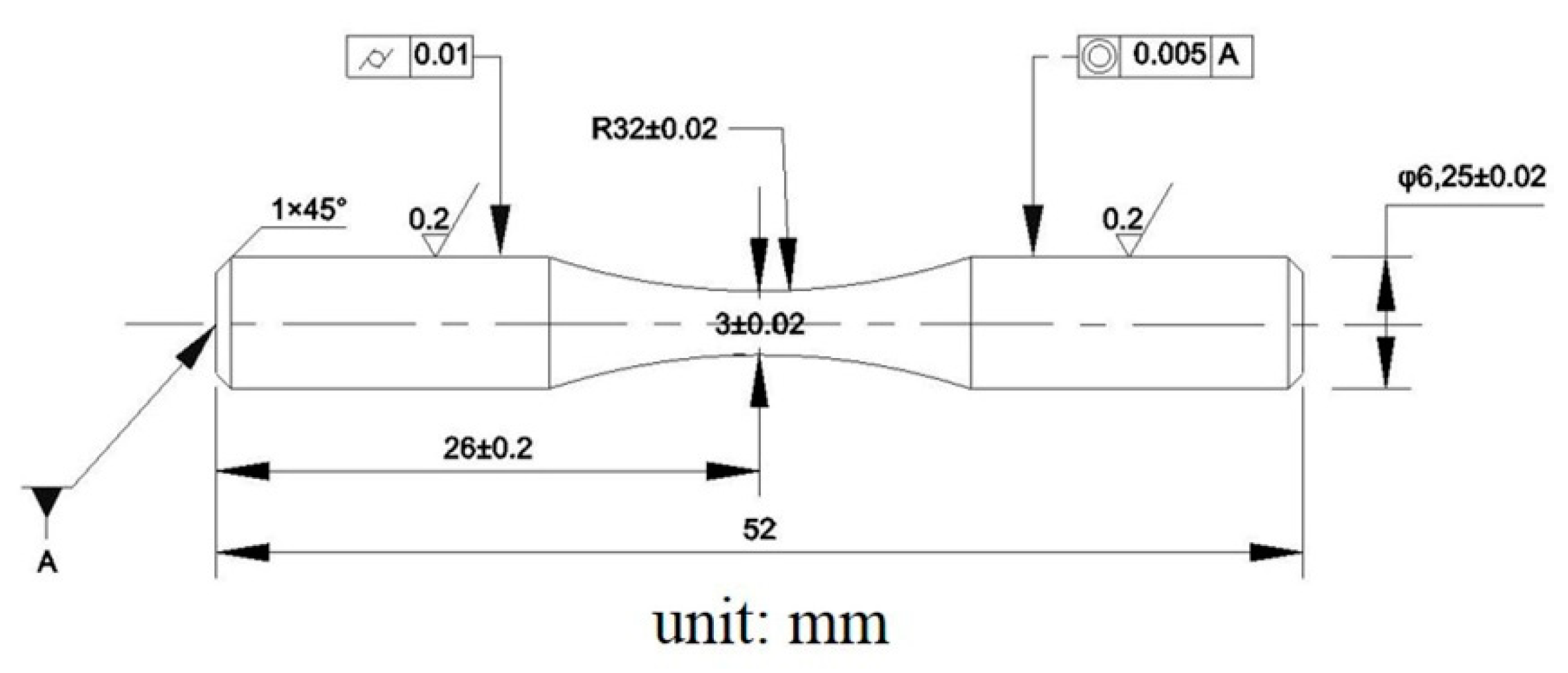
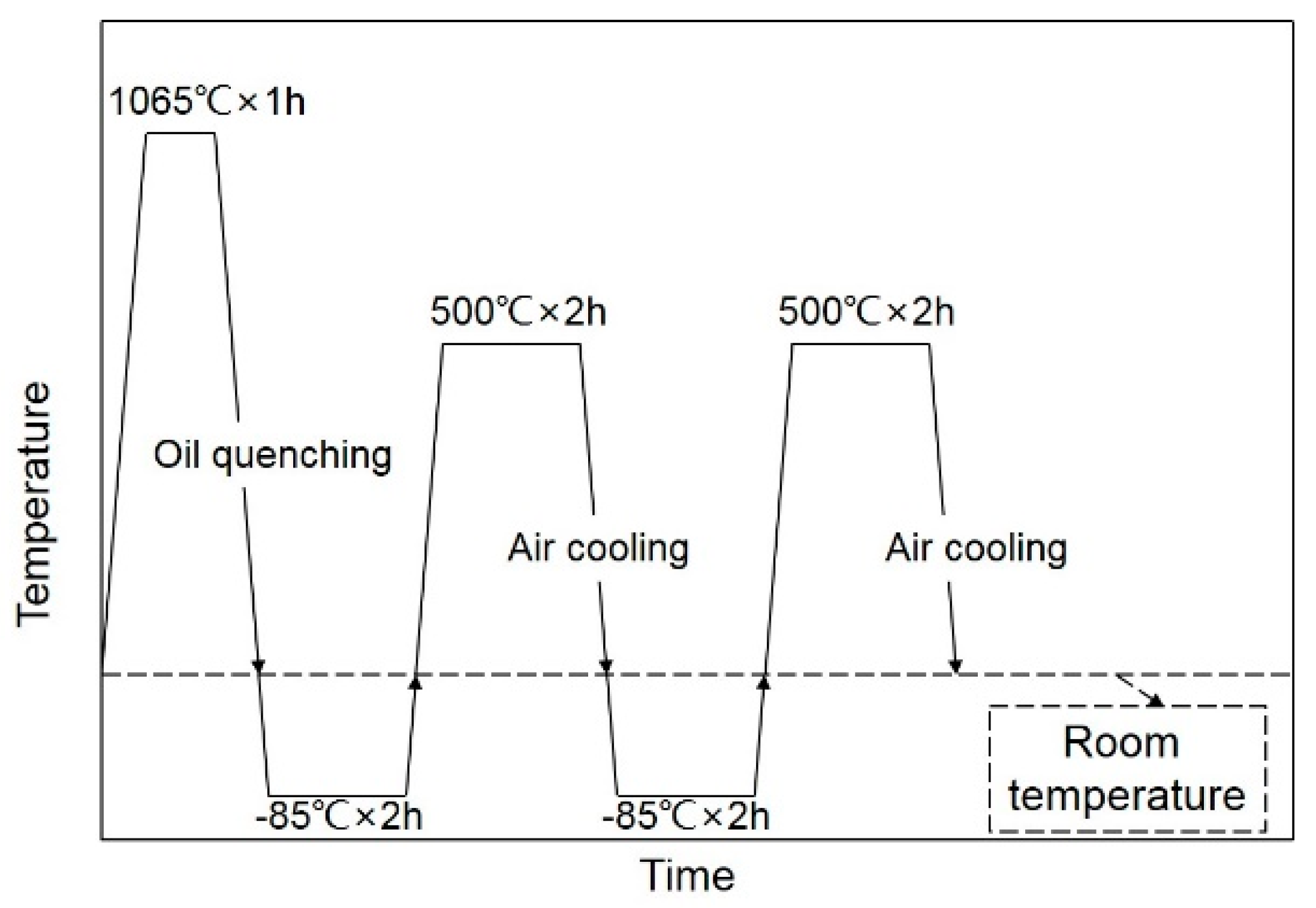
2. Materials and Methods

The test material was high-alloy stainless carburized bearing steel, and its chemical composition is listed in Table 1. The ingots were forged into round bars after being smelted by vacuum induction melting (VIM) + vacuum arc remelting (VAR). The round bars, after annealing, were prepared into specimens along the longitudinal orientation for carburizing, as shown in Figure 1. The surface of the fatigue specimens was carburized by a vacuum low-pressure pulse carburizing process so as to obtain an effective carburized case depth of about 0.8 mm. The heat treatment was carried out after carburizing as shown in Figure 2. After heat treatment, the surface of the fatigue specimens was ground and polished to the final dimensions required for fatigue tests.
The tests were carried out on a QBWP-10000X type rotating bending fatigue test machine (Changchun Qianbang Test Equipment Co., Ltd., Changchun, China) according to GB/T 4337-2015 standard, with a test frequency of 80 HZ and stress ratio of −1 for all tests. The test temperature of one group was 500 °C, and the other group was carried out at room temperature (20 °C) for comparison. When the fatigue specimens did not fail at life more than 107 cycles, it was stopped and deemed to pass, and the fracture surface of the failed specimens was observed.
After being ground and polished, the microstructure of the carburized specimens was observed by means of optical microscopy after being etched in CuCl2 + HCL + H2O + ethanol solution until the surface turned gray. The microhardness of the specimens was examined using an FM300 type digital microhardness tester. The OLYMPUS LEXT OLS4100 3D Laser Scanning Microscope (Olympus Co., Ltd., Tokyo, Japan) was used to observe the morphological characteristics of different fracture areas. The FEI Quanta 650 FEG scanning electron microscope (SEM) (FEI Company, Hillsboro, OR, USA) was used to observe the fracture and microstructure and an energy dispersive spectrometer (EDS) (FEI Company, Hillsboro, OR, USA) was used to analyze high-temperature oxides. Electron backscatter diffraction (EBSD) technology (FEI Company, Hillsboro, OR, USA) was used to analyze the crack growth path. The Image-Pro Plus software (Version 6.0.0.260) (Media Cybernetics, Inc., Rockville, MD, USA) was used for counting the carbides of different test temperatures.

3. Experimental Results

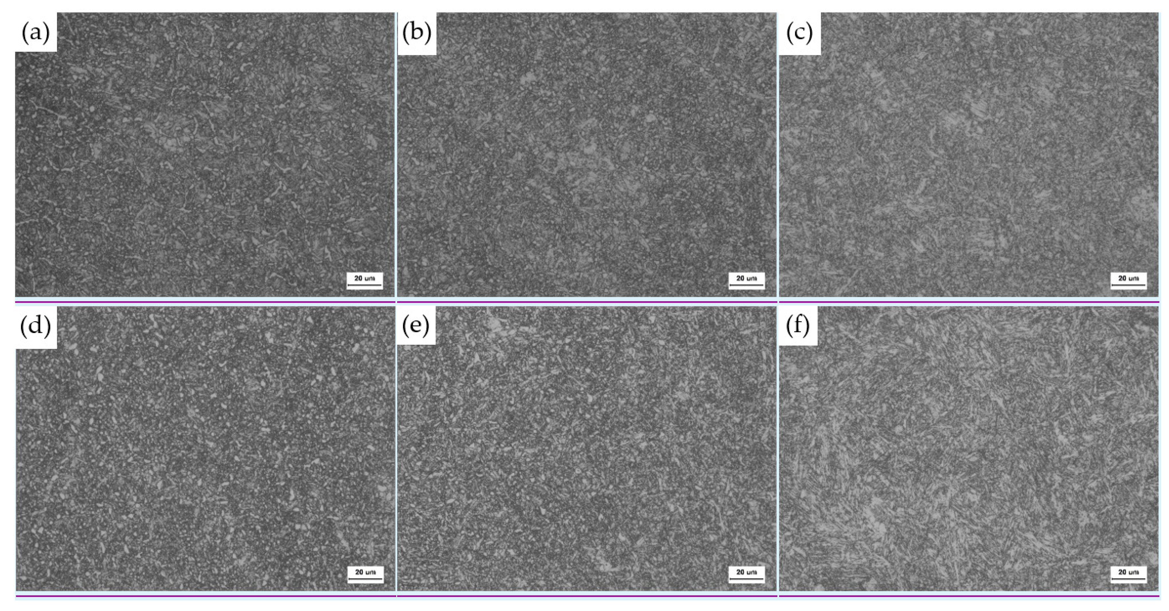
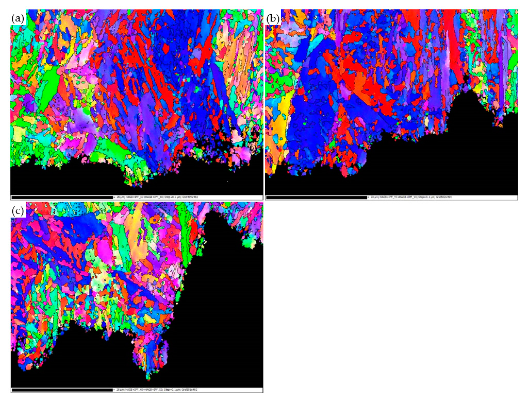
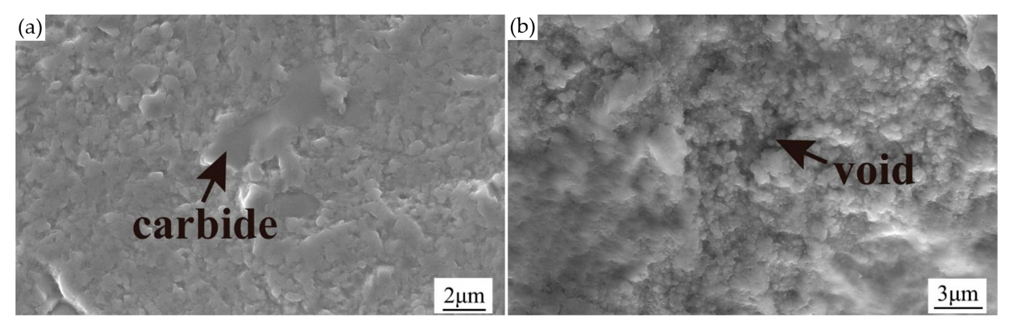
3.1. Microstructural Characterization of the Carburized Case

The microstructures of 15Cr14Co12Mo5Ni2 bearing steel at room temperature are shown in Figure 3a–c. As can be seen from Figure 3a, the carbides of the carburized case are distributed along grain boundaries, and the matrix is cryptocrystalline martensite. With the decrease of carbon content, globular carbides precipitate in the matrix of the transition zone, as shown in Figure 3b. The size of carbides in the core is small and the number is significantly reduced. The microstructure of the matrix is typical tempered martensite and residual austenite, as shown in Figure 3c.
Figure 3d–f shows the microstructure of the passed specimens for which the cycles exceeded 107 at 500 °C. Compared with room temperature, the microstructures of 15Cr14Co12Mo5Ni2 bearing steel are different from those after thermo-mechanical coupling at 500 °C. Firstly, some large carbides on the grain boundary of the carburized case were dissolved, and the carbides were distributed evenly in the matrix and the size decreased. Then, as the distance from the surface increases, the number of carbides decreased. Finally, most of the carbides in the core were dissolved in the matrix, and only a small amount was distributed at the interface of the martensite lath. The matrix was tempered martensite and retained austenite.

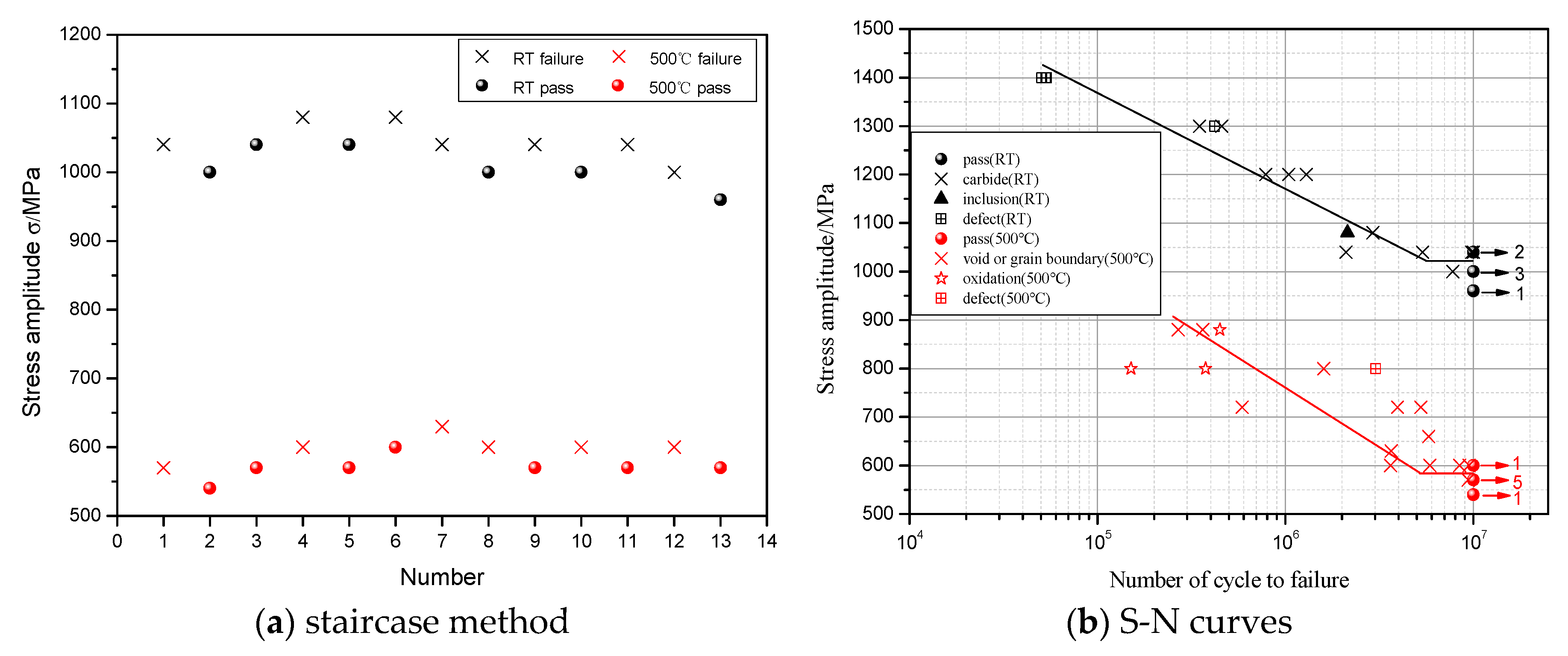
3.2. Staircase Method and S-N Curves

Figure 4 shows the staircase method and S-N curves of 15Cr14Co12Mo5Ni2 bearing steel at room temperature and 500 °C. As can be seen in Figure 4a, the stress levels at room temperature and 500 °C were 4 grades, and the fatigue strength at room temperature and 500 °C were calculated to be 1027 MPa and 585 MPa, respectively, which was 43.0% lower than that at room temperature, indicating the harmful effect of high temperature on the fatigue properties of 15Cr14Co12Mo5Ni2 bearing steel. In all cases, the fatigue life tended to decrease with the increase of stress amplitude at different temperatures, and the data at 500 °C were more dispersed than that at room temperature, as shown in Figure 4b. The number indicated by the arrows in Figure 4b is the number of pass specimens under the stress amplitude.

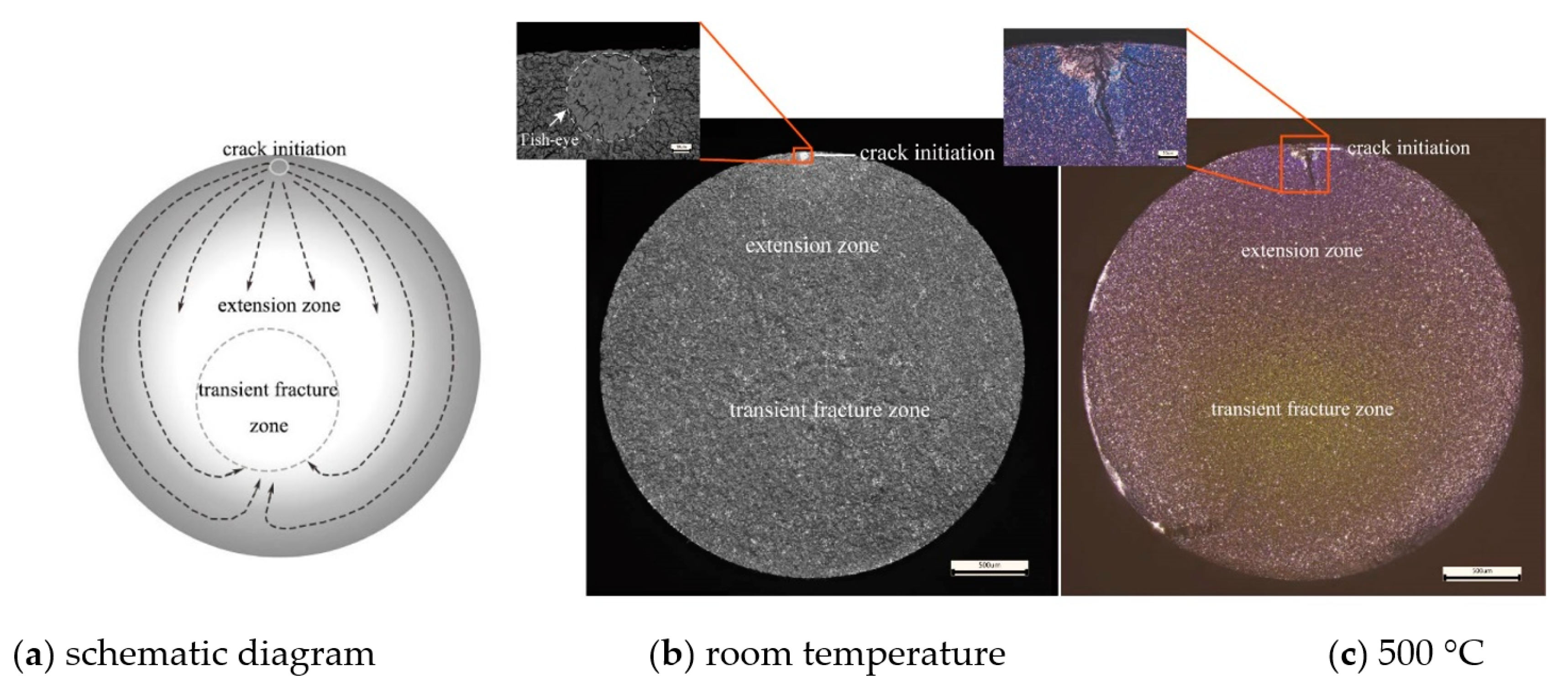
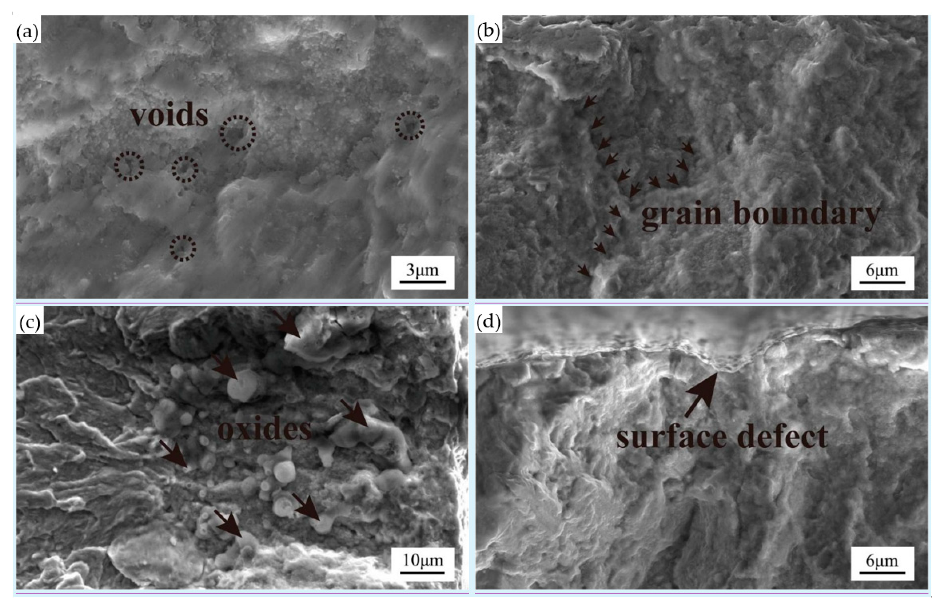
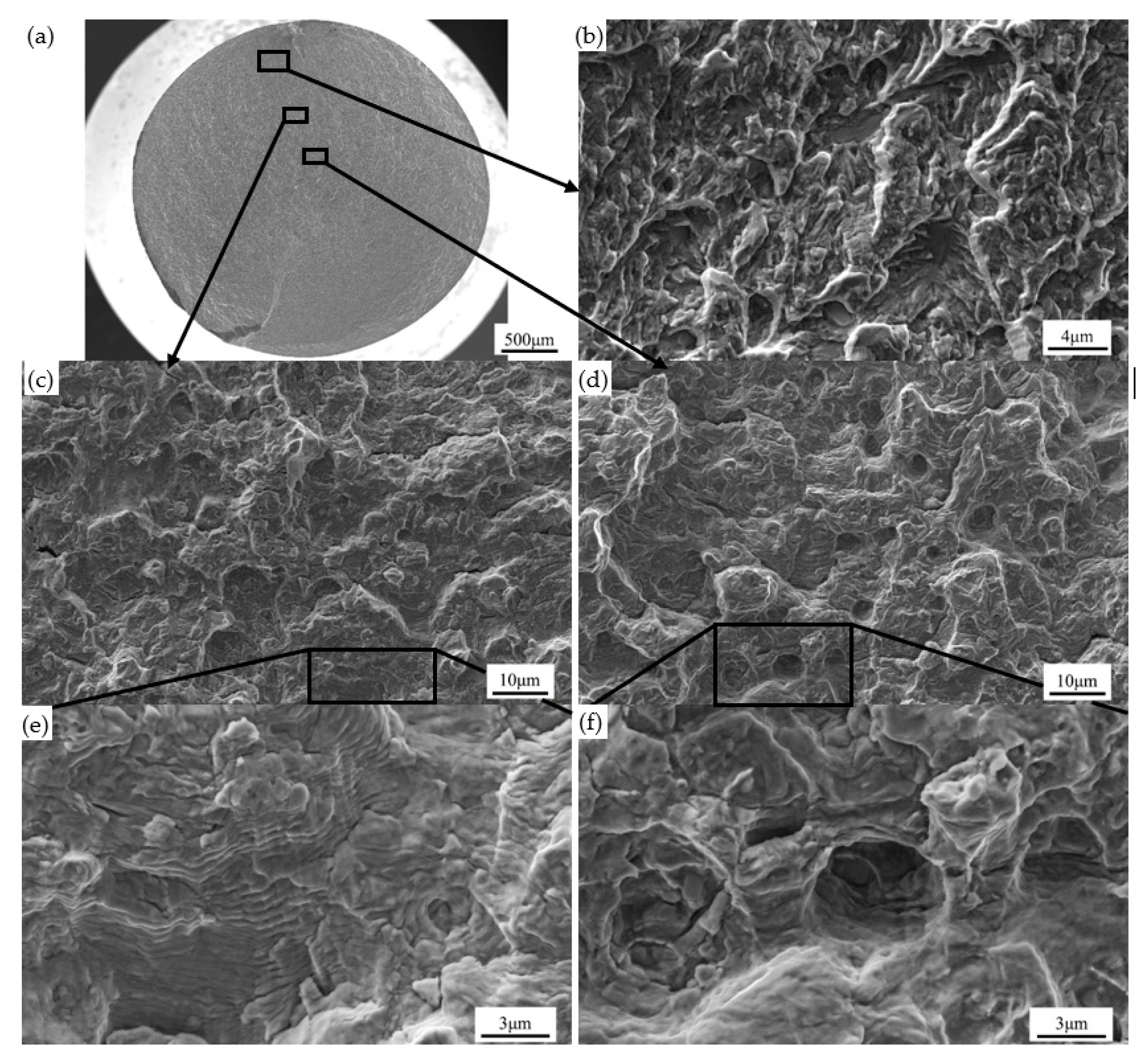
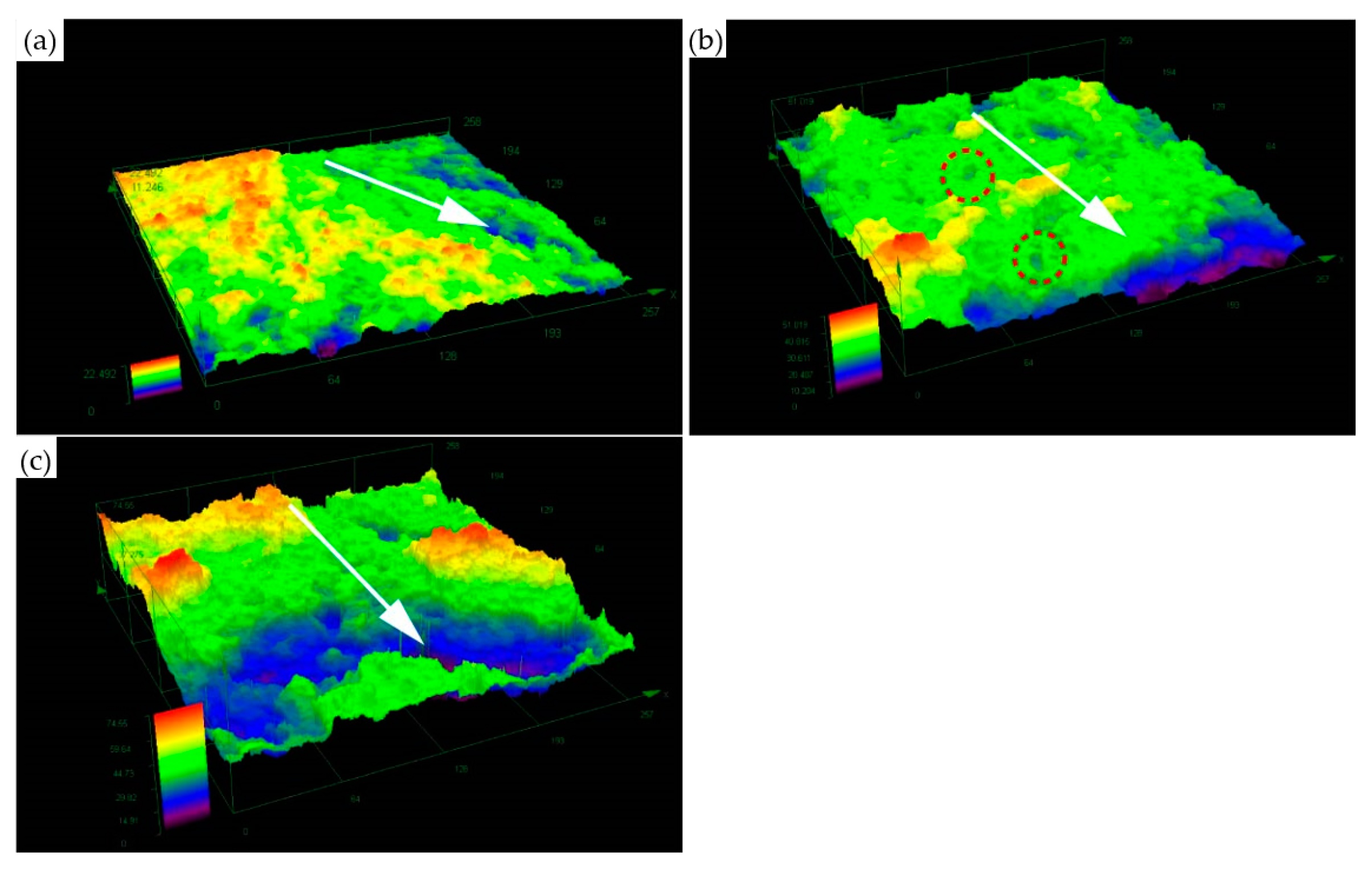
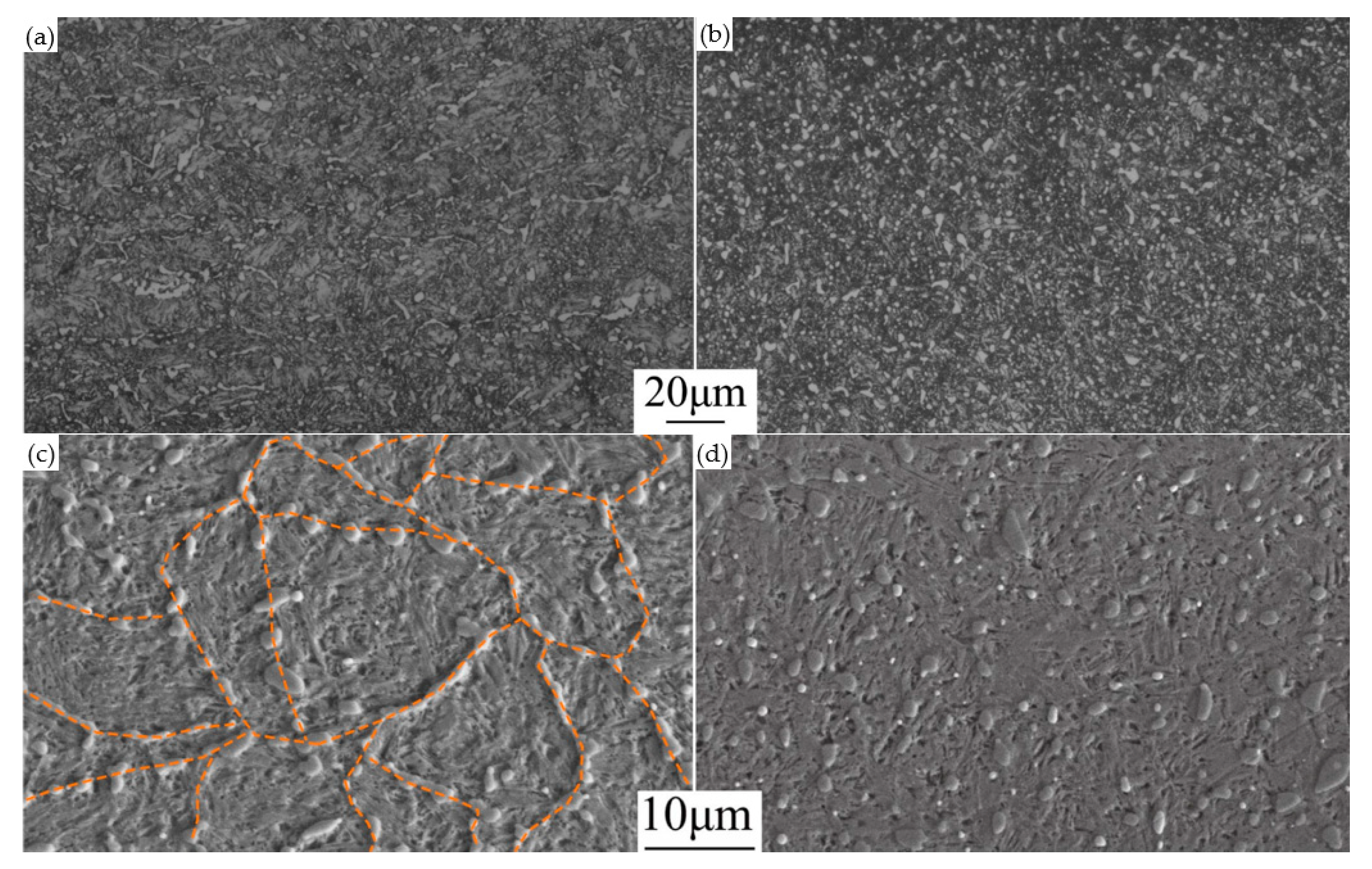
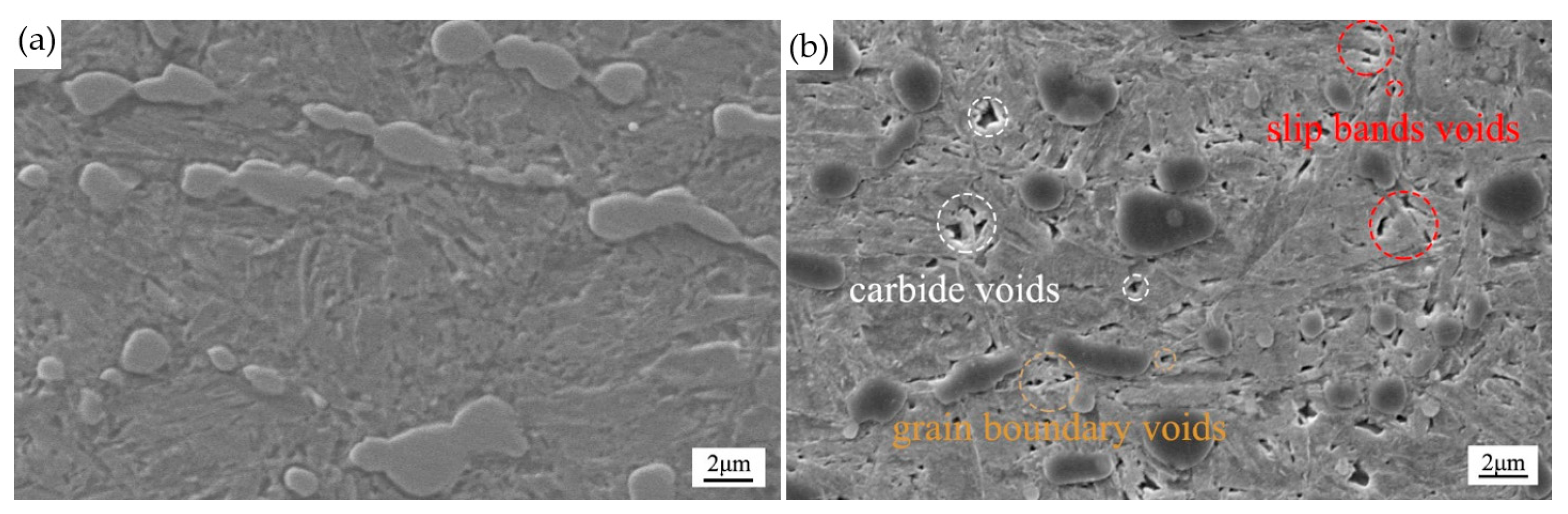
3.3. The Fracture Morphology

At room temperature and 500 °C, the fractures formed flat and perpendicular to the axial direction, as shown in Figure 5. The schematic diagram is shown in Figure 5a. It was evident that the initiation mode of 15Cr14Co12Mo5Ni2 bearing steel was a single source, and the fracture was composed of crack initiation, extension zone, and transient fracture zone. After the crack initiated at the crack source, it propagated along the carburized case, firstly under the action of cyclic stress. When the crack passed through the carburized case, it began to propagate to the core, and the transient fracture zone was located in the interior of the specimens. After initiating, the crack propagated along the carburized case until they met and then instantaneous fracture occurred in the core of the fatigue specimens. The reason for this phenomenon is that the carburized case is brittle, which leads to the crack propagating rapidly in the carburized case, but slowly in the core. Due to the influence of surface defects, the propagation path may be changed when the crack propagates in the carburized case, leading to cracks not being in the same plane when they meet and the “ratchet” morphology forming on the fracture surface.
The fish-eye region was observed in specimens that were tested at room temperature and the center of the fish-eye was a single carbide or small-sized carbide cluster, as shown in Figure 5b. There was no fish-eye in the crack source at 500 °C, as shown in Figure 6b. At high temperature, the fresh metal surface is easily oxidized after crack initiating, and the longer the crack is exposed to the air, the higher the oxidation degree is. According to the oxidation degree of the fracture surface, it can be seen that the initiation and propagation of cracks occupy most of the fatigue life of 15Cr14Co12Mo5Ni2 bearing steel, as shown in Figure 5c. The rate of crack propagation in the carburized case is faster, so the degree of oxidation is lighter. When the crack is finally fractured in the center, the speed is faster, and the oxidation degree is the lowest in high-temperature environments. The crack in the carburized case grows faster, so the degree of oxidation is less. At the end of the fracture, the rate of crack propagation is very fast, and the degree of oxidation is the lowest in high-temperature environments.
All the fractured surfaces of the rotating bending fatigue specimens at 500 ℃ were observed and it was evident that there are four types of fatigue fracture initiation, as shown in Figure 6. Most of the fractured specimens in 15Cr14Co12Mo5Ni2 bearing steel at 500 ℃ were found to initiate from grain boundary and voids, as shown in Figure 6a,b. Oxides were a secondary factor causing fractures, accounting for 17.6% and only 5.9% fatigue fracture origins were surface defects, as shown in Figure 6c,d respectively. After initiating, the crack propagated to the core along the direction perpendicular to the surface.
It is well known that ductile fracture and cleavage fracture are the most common fracture mechanisms in metals. Figure 7 shows scanning electron microscope fractography of the fracture surfaces of 15Cr14Co12Mo5Ni2 bearing steel at 500 °C at the crack propagation stage. There are three zones: one with a quasi-cleavage fracture in the carburized case; another with fatigue fracture in the middle stage; and the other with the combined mode in the later stage.
The cracks propagate in the carburized case first, showing the characteristics of transgranular fracture. The matrix strength of the carburized case is high, but the toughness is poor, and small cleavage planes and tearing ridges on the fracture are observed, which prove that this stage is a quasi-cleavage fracture, as shown in Figure 7b. There are a lot of large carbides in carburized case, causing cracks to break through the carbides or propagate along the edge of the carbides when the cracks meet the carbides. In other words, the carbides in the carburized case accelerate the crack propagation process. At the early stage of crack propagation, fatigue damage is dominant, but fatigue characteristics, such as fatigue striations, are not found on the fracture surface. The crack propagation rate is fast in the carburized case, resulting in fatigue characteristics that are not obvious.
In the middle stage of crack propagation, the rate of crack propagation decreases with the increase of matrix toughness, so obvious fatigue fringes appear on the fracture, as shown in Figure 7c. Fatigue striations are the basic characteristics of fatigue fracture. Figure 7e shows that each fatigue striation is parallel to each other basically, and the direction is perpendicular to the local crack propagation direction and the fatigue striations protrude outwards along the crack propagation direction. Due to the difference of grain or boundary orientation, the fatigue striations in different regions are distributed in different planes and directions. The secondary cracks appear with the fatigue striations, which are parallel to the fatigue striations and perpendicular to the crack propagation direction.
The fracture morphology at the later stage of crack propagation is shown in Figure 7d. As the cracks propagate from the carburized case to the core, the matrix toughness increases, and the fatigue striations become more and more obvious. At the same time, the secondary cracks also increase accordingly. Under the influence of temperature and plastic of matrix, there are obvious creep voids on the fracture surface, which are observed after being magnified, as shown in Figure 7f. It is evident that there are carbides at the bottom of the voids, and cracks are found at the edge of the carbides. In addition, fatigue striations are found at the inner wall of the voids, which indicates that the creep voids are affected by fatigue. Thus, crack propagation is affected by the interaction of fatigue and creep in the later stage.
The most noteworthy microscopic characteristic of ductile fracture of metals is the presence of dimples. Figure 8 shows scanning electron microscope fractography of the fracture surfaces of 15Cr14Co12Mo5Ni2 bearing steel at 500 °C at the transient fracture zone. It is evident that there is a characteristic of static tensile on the transient fracture zone that the fracture surface is equiaxed dimples, and there is a carbide at the bottom of each dimple, indicating that the specimen is subjected to normal stress at the final fracture. At high temperature, the interface between carbides and matrix is weak, which leads to the formation of microscopic voids at carbides. Nucleation, growth, and coalescence of microscopic voids result in dimple morphology.
Based on the Paris formula, Jeglic considered the influence of activation energy on the crack propagation rate and proposed the Arrhenius empirical formula [11]:
d a d N = A e x p [ u ( Δ K ) R T ]
where, A is constant, u ( Δ K ) is activation energy, R is Boltzmann constant, and T is absolute temperature. It can be seen from Formula (1) that the fatigue crack propagation rate increases with the increase of temperature. At high temperature, the contribution of creep to crack propagation increases, which leads to the increase of crack propagation rate and the decrease of high-temperature fatigue strength.
Figure 9 shows the 3D morphologies at different locations of the failure fracture and the arrows indicate the crack propagation direction. In the early stage of the crack propagation in the carburized case, it shows quasi-cleavage fracture. The fracture surface in this area is relatively flat and perpendicular to the tensile stress direction, as shown in Figure 9a. In the middle stage of crack propagation, the fracture surface generally has little fluctuation, and a few creep voids were observed in this area, as shown by the red dotted line circle in Figure 9b. At the later stage of crack propagation, the plastic of steel increase and the fracture surface fluctuate greatly, as shown in Figure 9c.
The fracture was cut along the crack propagation direction, and the crack propagation path was observed by means of EBSD. The results are shown in Figure 10. In the early stage of crack propagation, the size of the martensite block near the crack is larger, followed by the middle stage, and the smallest in the later stage. The corresponding fracture surface morphology is flat in the early stage, slightly fluctuant in the middle stage, and greatly fluctuant in the later stage. It indicates that the crack propagation path is related to the martensite block. Since the size of the martensite block is large, the propagation path is not easy to change, as shown in Figure 10a. With the decrease of the size of the martensite block, the path is changed constantly during the process of crack propagation. Therefore, the smaller the size of the martensite block is, the more difficult the crack propagation is, and the greater the fluctuation of fracture morphology is, as shown in Figure 10b,c.
As described on the previous page, the fracture mode of steel at 500 °C transformed from a quasi-cleavage fracture in the early stage to a ductile fracture in the later stage, and the failure mode changed from fatigue to creep–fatigue interaction during the process of crack propagation from carburized case to the core.

4. Discussion

4.1. Effect of Voids on Rotating Bending Fatigue Properties

Figure 11 shows the scanning electron microscope of the crack initiation source at room temperature and 500 °C. Compared with room temperature, although no “fish-eye” feature is found at the fracture initiation source at 500 °C, a granular bright facet (GBF) zone exists on the fracture surface, which has no fixed shape, and no carbide or inclusion is found in the GBF zone. The GBF zone is the symbol of crack initiation and early propagation, which accounts for most of the fatigue life. There have been many studies on the formation mechanism of GBF in the existing literature. Murakam et al. [12] found that hydrogen plays an important role in the formation of the GBF zone of high strength steel. Yang et al. [13] found that the enrichment of hydrogen in the high-stress region led to the initiation and early propagation of cracks at the non-metallic inclusions. Shiozawa et al. [14] proposed the ‘dispersive decohesion of spherical carbide’ model. It was believed that the formation of the GBF zone was related to the dispersed spherical carbides near the non-metallic inclusion, which led to the initiation of cracks, and, at the same time, the cracks grew along the interface between spherical carbides and the matrix. Hong et al. [15] believed that the GBF zone was caused by numerous cyclic pressing between the initiation crack surfaces. The hydrogen content of 15Cr14Co12Mo5Ni2 bearing steel is strictly controlled below 1 ppm, and no spherical carbides are found on the fracture surface. Thus, it is reasonable to believe that the formation of the GBF zone is related to repeated extrusion between the initiation crack surfaces.
Figure 11a shows the morphology of the GBF zone at room temperature. It can be seen that there are large carbides in the center of the GBF zone. At the initial stage of GBF formation, plastic deformation accumulates at the edge of carbides, resulting in the initiation of microcracking. The GBF zone is actually a thin layer of nanograins [15]. The microcracks are repeatedly pressed, resulting in local severe plastic deformation on the cracks surface, which causes grain refinement, thus the formation of GBF zone. As shown in Figure 11a, there are traces of numerous cyclic pressing on the surface of the GBF zone, which proves that cracks initiate first and then the GBF zone is formed. Compared with room temperature, the crack initiation source at 500 °C has both similarities and differences. The similarity is that the GBF zone is found and there are traces of numerous cyclic pressing on the GBF zone at room temperature and 500 °C, indicating that the formation mechanisms of the GBF zone do not change at 500 °C. The difference is that the direct cause of the formation of the GBF zone at 500 °C is not carbides, but voids, as shown in Figure 11b.
In order to analyze the reason for the formation of voids at 500 °C, the microstructure of the carburized case at room temperature and 500 °C were analyzed. Figure 12 shows the hardness distribution at the cross-section of 15Cr14Co12Mo5Ni2 bearing steel, which is tested at room temperature and 500 °C. It is evident that surface hardness and core hardness are not obviously different for the two curves, indicating that the temperature has little effect on the hardness of the carburized case. In addition, from the hardness curves, it is known that the hardness decreases from the surface to the core gradually and the effective carburized cases depth of fatigue specimens are about 0.8 mm. The carbides morphology of the carburized case at room temperature and 500 °C are observed, and the carbides are counted. The results are shown in Figure 13 and Table 2. Carbides larger than 3 μm and smaller than 1 μm are defined as large carbides and small carbides respectively. Figure 13a,c shows the microstructure and morphology of the carburized case at room temperature, and it can be seen that the carbides in the carburized case are distributed on the grain boundary. Figure 13b,d shows the microstructure and morphology of the carburized case at 500 °C. It is evident that due to the effect of the thermo-mechanical coupling, most of the large carbides on the grain boundary dissolve into the matrix, which leads to a large number of small-size carbides precipitating on the grain boundaries and in the grains. As can be seen from the data in Table 2, at 500 °C, the area percentage of carbides in the carburized case and the number of small carbides less than 1 μm are higher than those at room temperature, while the number of large carbides larger than 3 μm is significantly reduced, and the carbide spacing is smaller than that at room temperature. When the rotating bending fatigue specimens are tested at 500 °C for a long time, the martensite decomposes and the matrix softens. However, at the same time, the carbides precipitating in the matrix can strengthen the matrix, thus counteracting the softening effect of the matrix. Therefore, the hardness of the carburized case has little change at room temperature and 500 °C, as shown in Figure 12.
Geng et al. [7] studied the effect of temperature on the rotating bending fatigue property of 15Cr14Co12Mo5Ni2 bearing steel without carburizing. It is found that the hardness of the matrix decreased at 500 °C, and the harmonious deformation of the matrix through slip under the action of alternating cyclic stress leads to that the persistent slip band is extruded on the surface of the specimen, resulting in the fatigue failure of 15Cr14Co12Mo5Ni2 bearing steel. After carburizing, a large number of small carbides precipitate from the carburized case at 500 °C, which effectively prevent the matrix from sliding. Therefore, no persistent slip band is found on the surface of 15Cr14Co12Mo5Ni2 bearing steel after carburizing.
Figure 14 shows the microstructure of the carburized case of the specimens, which have not failed at room temperature and 500 °C. No voids are found after the test at room temperature, as shown in Figure 14a. At 500 °C, there are a lot of voids at the edge of the large carbides, the small carbides on the grain boundaries and at the clean grain boundaries, as shown in Figure 14b. As can be seen in Figure 13b,d, some large carbides on the grain boundary do not dissolve at 500 °C, which means that when the specimens are subjected to cyclic stress, the large carbides can hinder the grain boundary from sliding. Due to the obstruction of carbides, the grain boundary cannot coordinate the deformation sufficiently, and stress concentration occurs at the large carbides. Moreover, the bonding force between the matrix and the carbides at the grain boundary is weak, so the voids are easily nucleated at the large carbides in the grain boundary. When the grain boundary sliding needs to be coordinated by means of the plastic deformation inside the grain, it can be completed through the slip of dislocations. At this time, the small carbides in the grain can hinder the plastic deformation, which can be expressed by the following formula [4]:
τ = ( F m 2 T ) 3 / 2 ( 2 T b · r · ( 2 π 3 f ) 1 / 2 )
where, τ is the external stress; T is the line tension of dislocation; F m is the resisting force on dislocation; b is the Burgers vector; r is the radius of carbides; f is the volume fraction of carbides. From formula (2), it can be seen that the smaller the carbide size and the larger the volume fraction inside the grain, the stronger the hindrance to dislocation will be, and the more likely the voids will be formed at the small carbides. In the process of plastic deformation, the intragranular dislocations are mainly concentrated in the slip band [7]. When the slip bands move to the grain boundary, the stress concentration occurs on the grain boundary, which leads to the nucleation of voids at the grain boundary.
It is well known that cracks generally initiate at the defect. The microcracks of fatigue source mainly initiate at the edge of carbides at room temperature and at voids at 500 °C for 15Cr14Co12Mo5Ni2 bearing steel. At room temperature, a large stress is required for crack initiation and propagation. However, at 500 °C, only small stress is required to cause the cracks to rapidly propagate. In other words, the process of crack initiation is absent at 500 °C because of voids in the carburized case. Therefore, the fatigue strength at 500 °C is significantly lower than that at room temperature.
According to the literature [7], the fatigue strength of 15Cr14Co12Mo5Ni2 bearing steel at 500 °C without carburizing and after carburizing is 667 MPa and 585 MPa, respectively, indicating that the influence of voids on the fatigue strength is greater than that of the persistent slip bands. After carburizing, the carburized case can partly offset the tensile stress by the residual stress produced by carburizing, to improve the fatigue strength of the steel, but the improvement effect is not enough to offset the negative effect of voids on the fatigue life.
Li et al. [10] believe that the reduction of tensile strength and yield strength at high temperature is the reason for the reduction of high-temperature fatigue strength. It can be seen from Figure 15, which shows the matrix strength of 15Cr14Co12Mo5Ni2 bearing steel at room temperature and 500 °C, that the increase of temperature reduces the strength of the steel. Under the action of the same stress, the size of the plastic deformation zone at the crack tip increases at high temperature, and the irreversible plastic cumulative damage caused by cyclic stress aggravates the crack rate, thus resulting in a lower fatigue life at high temperature. In addition, it is a cantilever beam structure when the specimens are loaded, which means that the cracks will propagate only when the specimen is under tensile stress, and compression stress makes the cracks close, that is, the negative stress does not contribute to the crack propagation. Compared with room temperature, the crack can be opened under low-stress amplitude at high temperature due to its lower strength, showing low resistance properties to crack propagation, thus resulting in lower fatigue life at high temperature.

4.2. Effect of High-Temperature Oxides on Crack Initiation and Propagation

At 500 °C, the surface of steel is easily oxidized in the air, and the higher the temperature is, the more serious the oxidation will be. By observing the central cross-section of the passed specimens, it is found that the surface is oxidized under the action of high temperature, and an oxide layer with an average thickness of 2.1 μm is formed on the surface. Microcracks are found in the oxide layer, as shown in Figure 16. Commonly, the deformation resistance of the oxide is generally greater than that of the matrix. The dense oxide layer generated on the surface and closely bound to the matrix can further strengthen the surface of the specimens and inhibit the initiation of cracks from the surface under the action of cyclic stress without rupturing and peeling [16]. However, the oxidation rate is controlled by the diffusion process of metal ions and oxygen ions, and the slow diffusion of alloy elements in the matrix at 500 °C leads to the limited growth rate of the oxide layer, which has little contribution to the improvement of the creep resistance of the specimens. On the other hand, the internal stress is generated in the oxide layer under the action of cyclic stress due to the inconsistent deformation rate between the oxide layer and the substrate, so that the microcracks in the oxide layer can initiate and propagate easy, thus generating macrocracks on the surface of the specimens, as shown in Figure 17. The incomplete oxide layers not only fail to strengthen the surface of specimens, but accelerate the initiation of cracks on the surface, making the oxygen in the air rapidly enter the matrix and then precipitate granular oxides or produce oxidation agglomerations on the subsurface, thus accelerating propagation of the cracks in the matrix, as shown in Figure 18. In the process of fatigue crack propagation at high temperature, the crack tip is always in a state of oxygen saturation, and it is easier to be oxidized than at room temperature. The oxide is a brittle phase, which is not conducive to the passivation of the crack tip. On the one hand, the increase i temperature improves the plasticity of the matrix, which prevents crack propagation. on the other hand, the oxidation of the crack tip accelerates the crack propagation [17]. Obviously, the acceleration effect is greater than the prevention effect, thus reducing the fatigue life of the steel.

5. Conclusions

In this study, the fatigue performance of 15Cr14Co12Mo5Ni2 bearing steel has been investigated by means of rotating bending fatigue tests at room temperature and 500 °C. It can be concluded that fatigue strength at room temperature and 500 °C is 1027 MPa and 585 MPa, respectively. Under the action of thermo-mechanical coupling, the large carbides on the grain boundary of the carburized case are partially dissolved into the matrix, and the crack initiation location changes from the carbides at room temperature to the cavities at 500 °C. In addition, high-temperature oxidation and the reduction of matrix strength are other reasons for the reduction of fatigue strength.

Author Contributions

All authors have contributed to this work. Conceptualization, Z.W. and M.Y.; Methodology, Z.W., M.Y. and K.Z.; Validation, Z.W., M.Y. and K.Z.; Formal analysis, Z.W., M.Y. and K.Z.; Investigation, Z.W.; Resources, M.Y. and K.Z.; Data curation, Z.W. and M.Y.; Writing—original draft preparation, Z.W.; Writing—review and editing, Z.W., M.Y. and K.Z.; Visualization, Z.W.; Supervision, M.Y. and K.Z.; Project administration, M.Y.; Funding acquisition, M.Y. All authors have read and agreed to the published version of the manuscript.

Funding

This research received no external funding.

Data Availability Statement

The data presented in this study are available on request from the corresponding author.

Conflicts of Interest

The authors declare no conflict of interest.

References

  1. Xiao, N.; Hui, W.J.; Zhang, Y.J.; Zhao, X.L.; Chen, Y.; Dong, H. High cycle fatigue behavior of a low carbon alloy steel: The influence of vacuum carburizing treatment. Eng. Fail. Anal. 2020, 109, 104215. [Google Scholar] [CrossRef]
  2. Huang, S.; Zhsng, G.Q.; Wang, M.Q.; Tan, H.L. Fatigue properties of heavy-duty gear steel with different carburized depth. J. Iron Steel Res. Int. 2012, 24, 34–38. [Google Scholar] [CrossRef]
  3. Wang, B.; Yang, M.S.; Zhao, K.Y. Fatigue resistance of Surface-Carburized Cr-Co-Mo-Ni bearing steel refined by vacuum melting. J. Vac. Sci. Technol. 2016, 36, 838–843. [Google Scholar] [CrossRef]
  4. Zhang, J.S. High Temperature Deformation and Fracture of Materials, 1st ed.; Science Press: Beijing, China, 2007; pp. 100–107. [Google Scholar]
  5. Hou, Z.P.; Yang, M.S.; Zhao, K.Y.; Bai, L.G. Microstructure evolution research of Cr-Co-Mo-Ni gear and bearing steel under action of temperature and stress coupling. Iron Steel 2014, 49, 80–85. [Google Scholar] [CrossRef]
  6. Xie, S.X.; Li, J.K.; Hou, F.; Liu, Y.J.; Wang, Q.Y.; Zhang, J.H. Very high cycle fatigue behavior of CrMoW rotor steel at different temperature. Chin. Meas. Test. Technol. 2015, 41, 13–17. [Google Scholar] [CrossRef]
  7. Geng, S.Y.; Yang, M.S.; Zhao, K.Y. Influence of temperature on high cycle fatigue properties of high cobalt molybdenum stainless bearing steel. Iron Steel 2018, 53, 77–85. [Google Scholar] [CrossRef]
  8. Lin, H.; Yang, M.S.; Shu, B.P.; Li, J.X.; Luo, Z.Q. High temperature rotating bending fatigue behavior and damage mechanism of high nitrogen stainless bearing. J. Iron Steel Res. 2019, 31, 475–484. [Google Scholar] [CrossRef]
  9. Zhang, Z.H.; Yang, M.S.; Sun, S.Q.; Li, J.X.; Luo, Z.Q.; Li, N. High temperature fatigue properties and crack initiation and its expansion mechanism of high nitrogen bearing steel. J. Iron Steel Res. 2018, 30, 555–562. [Google Scholar] [CrossRef]
  10. Li, J.K.; Liu, Y.J.; Wang, Q.Y.; Hou, F. High-cycle rotate bending fatigue behavior of TC17 at elevated temperature. J. Sichuan Univ. Eng. Sci. Ed. 2014, 46, 198–202. [Google Scholar]
  11. Jeglic, F.; Niessen, P.; Burns, D.J. Temperature dependence of fatigue crack propagation in an Al-2.6Mg alloy. In Fatigue at Elevated Temperatures, 1st ed.; Carden, A.E., Mcevily, A.J., Wells, C.H., Eds.; ASTM International: West Conshohocken, PA, USA, 1973; pp. 139–148. [Google Scholar] [CrossRef]
  12. Murakam, Y.; Nomoto, T.; Ueda, T. Factors influencing the mechanism of superlong fatigue failure in steels. Fatigue Fract. Eng. Mater. Struct. 1999, 22, 581–590. [Google Scholar] [CrossRef]
  13. Yang, Z.; Li, S.; Liu, Y.; Li, Y.; Li, G.; Hui, W.; Weng, Y. Estimation of the size of GBF area on fracture surface for high strength steels in very high cycle fatigue regime. Int. J. Fatigue 2008, 30, 1016–1023. [Google Scholar] [CrossRef]
  14. Shiozawa, K.; Morii, Y.; Nishino, S.; Lu, L. Subsurface crack initiation and propagation mechanism in high-strength steel in a very high cycle fatigue regime. Int. J. Fatigue 2006, 28, 1521–1532. [Google Scholar] [CrossRef]
  15. Hong, Y.S.; Liu, X.L.; Lei, Z.Q.; Sun, C.Q. The formation mechanism of characteristic region at crack initiation for very-high-cycle fatigue of high-strength steels. Int. J. Fatigue 2016, 89, 108–118. [Google Scholar] [CrossRef] [Green Version]
  16. Nishijima, S.; Kanazawa, K. Stepwise S-N curve and fish-eye failure in gigacycle fatigue. Fatigue Fract. Eng. Mater. Struct. 1999, 22, 601–607. [Google Scholar] [CrossRef]
  17. Reuchet, J.; Remy, L. High temperature low cycle fatigue of MAR-M 509 superalloy II: The influence of oxidation at high temperatures. Mater. Sci. Eng. 1983, 58, 33–42. [Google Scholar] [CrossRef]
Figure 1. Schematic of rotating bending fatigue specimen.
Metals 11 00025 g001
Figure 2. Heat treatment process after carburizing.
Metals 11 00025 g002
Figure 3. Microstructures of room temperature and 500 °C. (a) carburized case at room temperature, (b) transition zone at room temperature, (c) room at room temperature, (d) carburized case at 500 ℃, (e) transition zone at 500 ℃ and (f) room at 500 ℃.
Metals 11 00025 g003
Figure 4. Staircase method and S-N curves of test steel at different temperatures.
Metals 11 00025 g004
Figure 5. Schematic diagram of fracture and fracture morphology at room temperature and 500 °C.
Metals 11 00025 g005
Figure 6. SEM fractography of four different fatigue fracture origins at 500 °C. (a) grain boundary, σ = 800 MPa, N f = 150,833, (b) voids, σ = 880 MPa, N f = 268,540, (c) oxides, σ = 880 MPa, N f = 448,004, (d) surface defect, σ = 800 MPa, N f = 3,021,271.
Metals 11 00025 g006
Figure 7. SEM fractography of crack propagation of transition zone at 500 °C of (a); σ   = 600 MPa, N f   = 9,462,402. At 500 ℃, the macroscopic morphology of the fracture is shown in (a). The cracks first propagate along the carburized case, showing the characteristics of quasi-cleavage fracture, as shown in (b). With the increase of cracks propagation depth, the fracture mode changes to fatigue fracture, which is characterized by obvious fatigue striations, as shown in (c,e). At the later stage of cracks propagation, fatigue striations and creep voids are found on the fracture, proving that the fracture of the stage is the result of the combined action of fatigue and creep, as shown in (d,f).
Metals 11 00025 g007
Figure 8. SEM fractography of transient fracture zone at 500 °C; σ = 600 MPa, N f = 9,462,402.
Metals 11 00025 g008
Figure 9. Laser scanning 3D morphology of transition zone. (a) the early stage of cracks propagation, (b) the middle stage of cracks propagation and (c) the later stage of cracks propagation.
Metals 11 00025 g009
Figure 10. Electron backscatter diffraction (EBSD) of crack propagation path at 500 °C. (a) the early stage of cracks propagation, (b) the middle stage of cracks propagation and (c) the later stage of cracks propagation.
Metals 11 00025 g010
Figure 11. SEM of the granular bright facet (GBF) zone at room temperature and 500 °C. (a) room temperature, σ = 1080 MPa, N f = 2,913,854 and (b) 500 ℃, σ = 600 MPa, N f = 3,628,558.
Metals 11 00025 g011
Figure 12. Hardness distribution of the carburized case at room temperature and 500 °C.
Metals 11 00025 g012
Figure 13. Carbides in the carburized case after the test at room temperature and 500 °C. (a,c) microstructure at room temperature, (b,d) microstructure at 500 ℃ temperature.
Metals 11 00025 g013
Figure 14. Nucleation position of voids at room temperature and 500 °C. (a) room temperature, (b) 500 ℃.
Metals 11 00025 g014
Figure 15. Strength of the test steel at room temperature and 500 °C.
Metals 11 00025 g015
Figure 16. Oxide layer on the steel surface at 500 °C.
Metals 11 00025 g016
Figure 17. Rupture of the oxide layer on steel surface at 500 ℃ σ   = 880 MPa, N f = 448,004.
Metals 11 00025 g017
Figure 18. Oxides in crack initiation source σ = 800 MPa, N f = 150,833.
Metals 11 00025 g018
Table 1. Chemical composition of experimental steel (wt.%).
CCr CoMoNiSP
0.09–0.1811.0–14.012.0–15.04.0–6.01.5–3.0≤0.002≤0.008
Table 2. Statistics of carbides in the carburized case after the test at room temperature and 500 °C.
Test Temperature/°CCarbide Diameter d/μm Percentage   of   Carbide   Area f /% Carbide   Spacing   l /μm Carbide Size Distribution/%
d < 1 μm1 μm ≤ d ≤ 3 μmd > 3 μm
Room temperature1.375.875.6932.7963.064.16
500 °C1.168.624.1052.2545.771.98
Publisher’s Note: MDPI stays neutral with regard to jurisdictional claims in published maps and institutional affiliations.

