Review

Laser Powder Bed Fusion of Potential Superalloys: A Review

by
Prince Valentine Cobbinah
*,
Rivel Armil Nzeukou
,
Omoyemi Temitope Onawale
and
Wallace Rwisayi Matizamhuka
Department of Metallurgical Engineering, Vaal University of Technology, Andries Potgieter Boulevard, Vanderbijlpark 1911, South Africa
*
Author to whom correspondence should be addressed.
Metals 2021, 11(1), 58; https://doi.org/10.3390/met11010058
Submission received: 21 September 2020 / Revised: 11 October 2020 / Accepted: 10 November 2020 / Published: 30 December 2020
(This article belongs to the Special Issue Sintering Process of Metallic Materials)

Abstract

:
The laser powder bed fusion (LPBF) is an additive manufacturing technology involving a gradual build-on of layers to form a complete component according to a computer-aided design. The LPBF process boasts of manufacturing value-added parts with higher accuracy and complex geometries for the transport, aviation, energy, and biomedical industries. TiAl-based alloys and high-entropy alloys (HEAs) are two materials envisaged as potential replacements of nickel-based superalloys for high temperature structural applications. The success of these materials hinge on optimization and implementation of tailored microstructures through controlled processing and appropriate alloy manipulations that can promote and stabilize new microstructures. Therefore, it is important to understand the LPBF technique, and its associated microstructure-mechanical property relationships. This paper discusses the metallurgical sintering processes of LPBF, the effects of process parameters on densification, microstructures, and mechanical properties of LPBFed TiAl-based alloys and HEAs. This paper also, presents updates and future studies recommendations on the LPBFed TiAl-based alloys and HEAs.

Graphical Abstract

1. Introduction

TiAl alloys are intermetallic alloys based on an ordered α 2 ( T i 3 A l ) phase with a hexagonal crystal structure (DO19) or a face-centred tetragonal structure (L10) γ (TiAl) phase. TiAl-based alloys, over the years, have been considered as suitable candidates for weight-saving components in advanced new generation automotive and aerospace engines. This is attributed to their desirable high-temperature performances which include high strength-to-weight ratio; impressive creep properties at elevated temperatures, excellent oxidation and corrosion resistance [1,2,3].
High-entropy alloys (HEAs), by composition, are defined as alloys designed with at least five (5) principal elements having concentrations between 5 and 35 at.% [4]. Currently, HEAs are one of the novel alloy design concepts used in designing next-generation alloys which are envisaged for a wide range of industrial applications. HEAs exhibit remarkable properties such as good thermal stability [5], high strength and toughness under extreme conditions [6,7], high hardness [8], excellent wear resistance [9], outstanding fatigue performance [10], distinctive electrical and magnetic properties [11,12] and an impressive corrosion and oxidation resistance [13,14]. Some applications of HEAs studied include for hydrogen fuel cells, catalysis, gradient magnetism, and high-temperature semiconductors [15,16,17,18,19,20].
The burden of manufacturing demands such as complex structures and mechanical properties of HEAs, and TiAl-based alloys limit the processing technology options for fabricating these two alloys. Almost 75% of the total research on these potential superalloys, thus far reported used vacuum arc melting as processing technique while others used the vacuum induction melting process [21,22]. The justification behind using vacuum arc melting is because of the high temperature (≤3000 °C) that can be realized, which is enough to melt most of the metals composing these alloys (especially in HEAs). However, alloys with low-boiling point elements pose a challenge with this processing technique. Compositional control of such alloys become increasingly difficult owing to the possibility of evaporation during melting [21]. The main constraint in the melting and casting route is the development of heterogeneous microstructure. This is due to segregation caused by the slow rate of solidification. Therefore, homogenization treatment needs to be performed to reduce the effect of heterogeneity in the microstructure.
Also, although other studies successfully used the mechanical alloying route to fabricate HEAs and TiAl-based alloys with uniform microstructure and homogeneous chemical compositions, some inherent challenges of the technique include the production of only small quantities of these superalloy powders at a time, unavoidable contaminations from the grinding media and the high tendency of oxidation of the powders [23,24].
The inherent low ductility of TiAl alloys make their processing challenging at ambient temperatures. HEAs, on the other hand, are difficult to machine owing to their high strength and toughness [8,25]. Hence, fabrication of these potential superalloys through the conventional methods are limited to simple shapes.
There is thus an opportunity to explore alternative techniques or preparation methods which not only produce better quality and more similar products but are also more versatile in terms of the range of product shape and size that can be obtained. Additive manufacturing (AM) is a flexible processing technique that in recent years has been used in the fabrication of challenging materials such as HEAs and TiAl-based alloys. AM is a globally recognised parts manufacturing technology capable of producing parts-on-demand with reduced costs, consumption of energy and carbon emissions [26]. The laser powder bed fusion (LPBF) technique is one example of the AM technology. Components fabricated by LPBF exhibit minimal surface roughness and high dimensional accuracy. Typical cooling rates of conventional melting processes are less than 100 K·s−1 whereas the LPBF process reaches cooling rates up to 106 K·s−1 [27]. Therefore, LPBF offers the benefit of generating refined grains and substructures within the grains, which enhances the overall mechanical properties of produced parts. In addition, the LPBF technology boasts of an infinite geometric freedom, variability, and versatility. It is used to fabricate functional prototypes and cellular lightweight structures. These structures grant engineers the opportunity to tailor the density and strength of products to meet specific applications [28,29], thereby making the LPBF technology one of the most used processing techniques.
The present paper features an overview of the AM technology with focus on LPBF. Two candidate superalloy materials (TiAl-based alloys and HEAs) rarely reported for the LPBF process are considered. The paper further discusses the metallurgical sintering processes of the LPBF technology, the effect of its process parameters on the densification, microstructures, and mechanical properties of these materials.

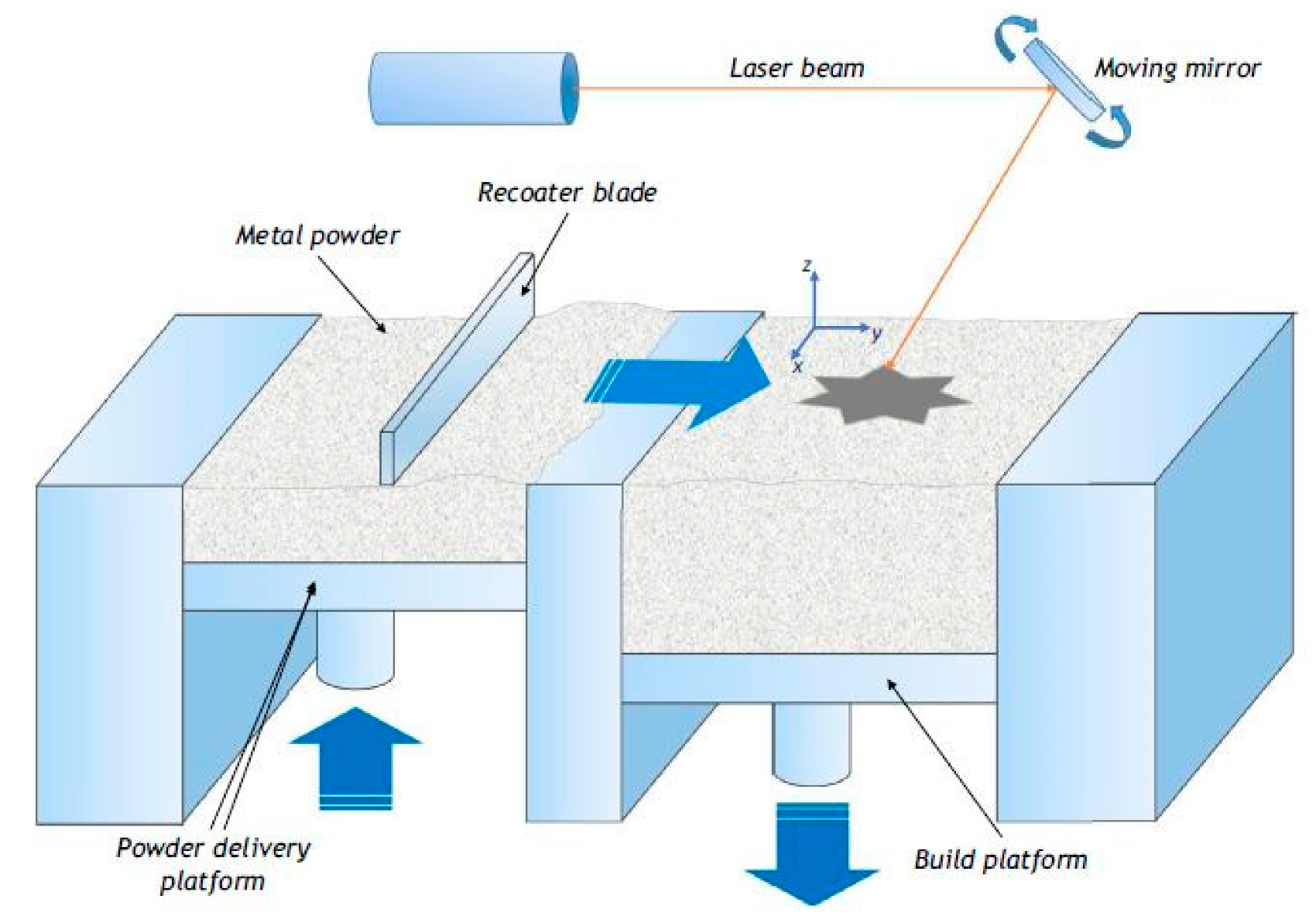
2. Laser Powder Bed Fusion (LPBF)

The LPBF AM process makes use of a laser beam energy source to melt and fuse powders in a layer-by-layer manner into a desired shape as illustrated by the schematic in Figure 1. In the LPBF process, a powder bed is created by the deposition of powder across a substrate (or platform). A computer-controlled electron or laser beam energy source supplies thermal energy to the surface of the powder bed melting the powder into the desired shape [26]. After the substrate is lowered by one-layer thickness. Additional powder is then levelled across the substrate, and the process is repeated until a solid 3D component form. Usually, the powders employed in the LPBF process are preheated to temperatures below their melting point to promote bonding and minimize distortion of the finished part. Additionally, the preheating tends to reduce laser power demands for the process. The environment in which the process is executed is essential to minimize the tendency of reactive powders oxidising. Thus, the LPBF process is usually performed in an argon inert gas-filled enclosed chamber. Some merits of the LPBF technology include [30,31,32]: (i) the ability to form complex geometries owing to the geometric freedom of the processes, (ii) efficient material usage, (iii) high solidification rates due to the local melting process, (iv) finer microstructures, (v) mass customisation, (vi) material flexibility (vii) the ability to produce internal orifices and high resolution features, and (viii) dimensional control. Disadvantages of the LPBF process are [33]: (i) high residual stresses, (ii) high surface roughness, (iii) high production cost, (iv) anisotropic properties (in general), (v) absence of on-line quality control, (vi) manufacturing accuracy versus build duration, (vii) evacuation of powder from small size channels are challenging.
The laser power employed in the LPBF process is much higher than in laser sintering processes. The LPBF was developed as an improvement of the selective laser sintering (SLS) technology to attain high densities for functional metallic prototypes, parts, or tools [35]. Again, compared to SLS, LPBF does not require the addition of a low melting point element to serve as a matrix during the process but instead utilizes the main metal powders. Furthermore, LPBF offers a higher energy density compared to SLS to achieve bonding of the powders. The higher energy density or laser power leads to complete melting of the powders ensuring that near fully dense or fully dense parts are achieved without the need for post-processing treatments [32]. This, on the other hand, assures reproducible properties [35]. The process takes place in an argon (Ar) atmosphere to minimize oxygen and nitrogen pickups.
The LPBF AM technology makes possible the fabrication of individual parts with complex geometries comparable or surpassing the mechanical properties of parts conventionally manufactured in series (such as in casting and cutting) [32,35]. In addition, LPBF requires no part-specific tooling and pre-production costs when processing the same materials in a series production like steels, nickel-, aluminium-, and titanium-based alloys [35].
During the LPBF process, the transient interaction of the heat source and powder bed caused by the high scanning speed of the laser beam culminate in rapid heating, melting and subsequent drastic shrinkage (from 50% powder apparent density to ~100% density in one step), and circulation of the molten metal driven by surface tension gradients coupled with temperature gradients [32,36]. The resulting heat transfer and fluid flow affect the size and shape of the melt pool, the cooling rate, and the transformation reactions in the melt pool and heat-affected zone. The melt pool geometry, in turn, influences the grain growth and the resulting microstructure of the part [32,36].
The melting-solidification transformation during the LPBF process is accompanied by substantial accumulated stresses. The development of residual stress from the melting and cooling processes and high thermal gradients can lead to cracks, distortion, and delamination of the final product. Usually, heat treatment by annealing may be used to reduce the residual thermal stresses or optimize the microstructure of the fabricated products. Additionally, in some cases, a post-processing (e.g., conventional machining or grinding) step is necessary to attain a high dimensional accuracy or a high-quality surface finish of the parts [37].
Also, the high energy level employed in the LPBF process can lead to vaporisation of the powders. As powders are continuously exposed to the laser beam, their temperature gradually increases and exceeds their melting temperature. An overheated powder particle will tend to move rapidly, generating overpressure in the melted zone and eventually ejects from the powder bed [38,39].
Moreover, melt instabilities owing to an excessive amount of energy density leads to the phenomenon known as spheroidization or balling effect of the melt pool [38]. This occurs when the molten powder has a low viscosity and is unable to fully wet the substrate due to surface tension [38]. This causes the formation of isolated spheres with a diameter equal to that of the focused laser beam [38]. The balling effect hinders deposition, increases porosity, and affects the final density of the built part.
Therefore, optimization and careful selection of processing parameters for the laser and powders deposition is paramount to achieve a suitable process window, in order to attain a moderate temperature field to avoid the overheating of the LPBF system [40].

3. Effects of Process Parameters on the LPBF Process

Several processing parameters influence the densification mechanism and accompanying microstructural features of materials processed by the LPBF AM technology. Table 1 lists some of the primary process parameters and materials properties essential to the success of the LPBF process.
Most metallic powders considered for the LPBF process are usually reactive. The higher surface area per unit volume of metallic powder particle surfaces compared to cast components means they have a greater susceptibility to contamination by adsorbed gases, moisture, oxide and nitride films and organics [41]. These contaminants result in insufficient wetting of the preceding layer and surface tension, thus hampering continuous melt lines or interlayer bonding and densification [42]. Consequently, the contaminations, coupled with thermal stresses lead to poor interlayer bonding, delamination, rough surfaces, degradation of mechanical properties, and part geometry of the LPBF built component [43]. Thus, various approaches have been utilised by different LPBF researchers to circumvent or mitigate contaminations and their attendant effects. Some include [38]:
  • executing the process in a vacuum or protective atmosphere (in high purity inert gases such as argon or nitrogen) to slow down or render the oxidation process inactive
  • alloying additions to disrupt formed surface oxide films
  • optimizing processing parameters to minimize the balling phenomenon
  • re-scanning of the underlying substrate to break up oxide films to ensure a clean surface at the atomic level between the liquid and the solid
The properties of parts fabricated by LPBF technology depend strongly on the properties of each single track and each single layer. The characteristics of track instability are influenced by the substrate material, laser beam power, scanning speed, powder layer thickness, physical properties and granulomorphometry of the powder used. Thus, optimization of the primary process parameters provides essential information in evaluating and understanding the features of a scan track.

3.1. Laser Types

The neodymium-doped yttrium aluminium garnet (Nd:YAG) and carbon dioxide (CO2) industrial lasers are historically, the two most used lasers in LPBF processing of metallic powders [44]. The main difference between the two lasers is their respective wavelengths [44]. Various applications in the past years preferred Nd:YAG lasers over CO2 lasers. As exemplified in Table 2, the absorptivity of most metals or metal matrix composites (MMCs) is higher with the shorter wavelength of the Nd:YAG lasers compared to the CO2 lasers at equivalent scanning speed and penetration depth [45].
It is envisaged that the energy efficiency of the LPBF process stands to improve as laser technology advances. In recent years, the ytterbium (Yb) doped fibre lasers are used as substitutes for Nd:YAG lasers in most AM applications. The Yb-fibre laser has an operational wavelength of 1.07 µm, capable of generating power up to 10 kW, energy efficiency of 10-30% and maintainance free for about 25,000 h [46]. Compared to other commercial lasers, the Yb-fibre laser offers some advantages such as a high electrical-to-optical efficiency (−25%), excellent beam quality and system compactness [47]. The shorter wavelength of the Yb-fibre laser beam permit light transmission through optical fibre cables instead of the articulated mirror delivery system employed for CO2 laser [48]. Hence, both the Yb-fibre and Nd:YAG laser beams can be easily guided with the laser source remotely from the LPBF workstation.
In addition, the optical fibre delivery system offers an avenue to deliver a light beam from a single laser source to multiple workstations. Thus, multiple processing operations can be simultaneously achieved with a single Yb-fibre laser source through the multifibre beam delivery [48]. LPBF processing with a Yb-fibre laser beam yields a more stable and slightly larger scan track compared to a CO2 laser beam [49]. Consequently, the wider Yb-fibre laser beam profile provides the ability to scan large tracks while maintaining the LPBF build quality and speed, which culminates to more uniform scan tracks with little or no porosity [49,50]. Again, compared to CO2 laser, the Yb-fibre and Nd:YAG lasers can operate at lower scanning speeds owing to the reduced interaction among beam, plasma and powder bed thereby allowing increased powder’s layer thickness to be melted [51]. Nonetheless, the Yb-fibre lasers are limited by the light propagation through the optical fibre. The optical fibre guiding medium affects the non-linear properties of the propagated light. The optical non-linear effect owing to the high peak power (some examples include Kerr lens effect, Raman effects, self-focusing and self-phase modulation) can limit the performances of the laser [46,52]. Additionally, the occurrence of fibre bending, vibration, and temperature variations leading to alterations in polarization can significantly influence the laser output [53]. Therefore, polarization maintaining optical fibres are usually suggested as the gain and light guiding medium for improved environmental stability [46].

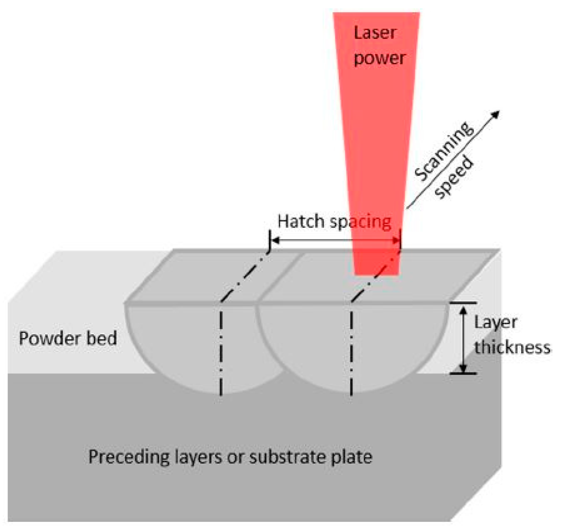
3.2. Effects of Processing Parameters on LPBF (Laser Power, Beam Size, Scanning Speed, Scan Hatch Spacing and Powder Layer Thickness)

Figure 2 illustrates the process parameters usually studied and optimized for the LPBF process. The LPBF process is heat-driven. The laser energy input, which is the source of heat for the consolidation of the powders, is a paramount factor of the LPBF process. It determines the state of the molten powder, including melting state, vaporization state and sintering state.
When the laser ray touches the powder particles’ surfaces, heat is generated and diffuses inward. A combination of low laser power and low scanning speed results in insufficient energy density to generate adequate liquid phase for binding particles together. This culminates in partial melting (SLS) leading to poor densification. Increasing laser energy at low scanning speed means more energy is delivered to the powder bed, causing the powder temperature to increase, followed by a significant amount of melting and formation of more liquid phase. The presence of adequate liquid phase improves densification owing to the reduction of surface free energy which leads to the instability of the liquid semi-cylinder. Therefore, it can be inferred that appropriate increments in the laser energy input lead to high working temperature, which eventually reduces both melt viscosity and surface tensions [41]. Moreover, the high working temperature promotes material transport due to the development of connective streams within the molten pool during the laser sintering process. This results in the reduction of the sizes and number of inter-agglomerate pores, hence achieving fully dense components. Nonetheless, according to Olakanmi et al. [54], at low scan rates with relatively high laser power, there exists an optimum laser energy density at which the wettability of the liquid-solid is most successful, such that the structural particles in the liquid are most suitably re-arranged to achieve higher sintered density. The increase in laser energy density after the optimum leads to decreased sintered density. In this condition, the higher laser power generated increases the quantity of liquid phase, but the reduced scan speed causes substantial increment in its lifetime, thereby promoting spheroidization and breakdown in the melt pool. The reduced sintered density in this case is attributed to significant aggregation of the structural particles. On the other hand, a high laser power with a low scanning speed may culminate in extensive material evaporation and the keyhole effect [55]. Similarly, Yuan et al. [56] showed there exists a scanning speed threshold beyond which the sintered density of materials also tend to decrease.
A combination of low laser power, high scanning rates and large layer thickness usually also culminate in insufficient energy [54]. This is because in this condition, not only is the laser energy produced low but also the high scanning rates means decreased interaction time. Thus, under high scanning speed and low laser power, the dimension of the formed molten pool will be too small, limiting the contact area between the molten pool and the substrate. This leads to lack of wetting, flowing, spreading characteristics and a corresponding balling phenomenon [57].
In addition, a thin powder layer thickness is favourable for scan track continuity and the overall success of the LPBF process. With a larger thickness, the layer energy absorbed in a unit powder volume is inadequate; hence the temperature of the molten pool is low, resulting in a weak flow ability and balling phenomenon [57]. Furthermore, although a bigger layer thickness can enable a big molten pool, the formed molten pool will be far away from the substrate, leading to a relatively small contact area between the molten pool and substrate. In this condition, the small wetting area may not support a big molten pool; thereby, the molten track will tend to break up into balls [57].
The use of greater laser power and scanning speed increase the efficiency of the LPBF process. With the increase of the beam scanning speed, heat loss by conduction decrease, and the absorbed laser radiation energy goes directly into fusing the material [58]. Hence, the width of the scanned tracks is comparable to the laser beam diameter [59].
Poor scan hatch spacing often results in regular porosity in built parts as adjacent melt lines do not fuse completely. The pores typically initiate at the single-layer level and are two scan tracks apart [60]. They can be eliminated by appropriately overlapping the neighbouring scan tracks. Increasing scan overlap reduces the melt pool depth or penetration leading to less bonding between layers. Nonetheless, Thijs et al. [60] suggested adjusting the scan hatch spacing to create a 25% scan overlap as a means of circumventing pores formation, which also leads to improved density.

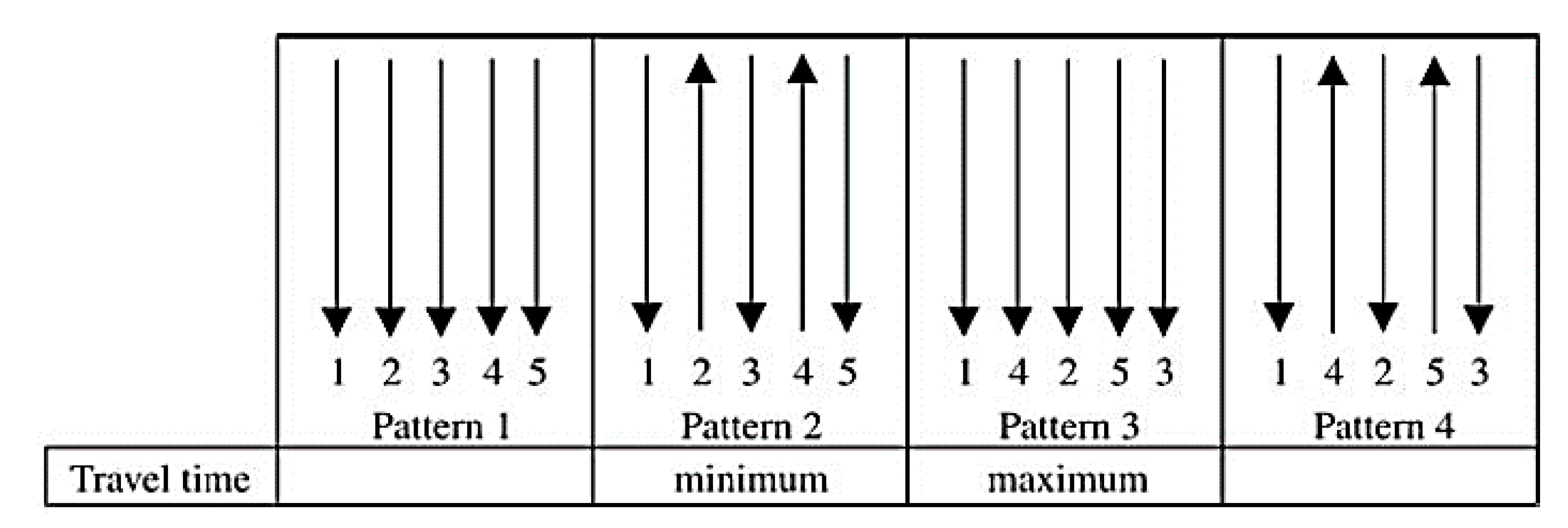
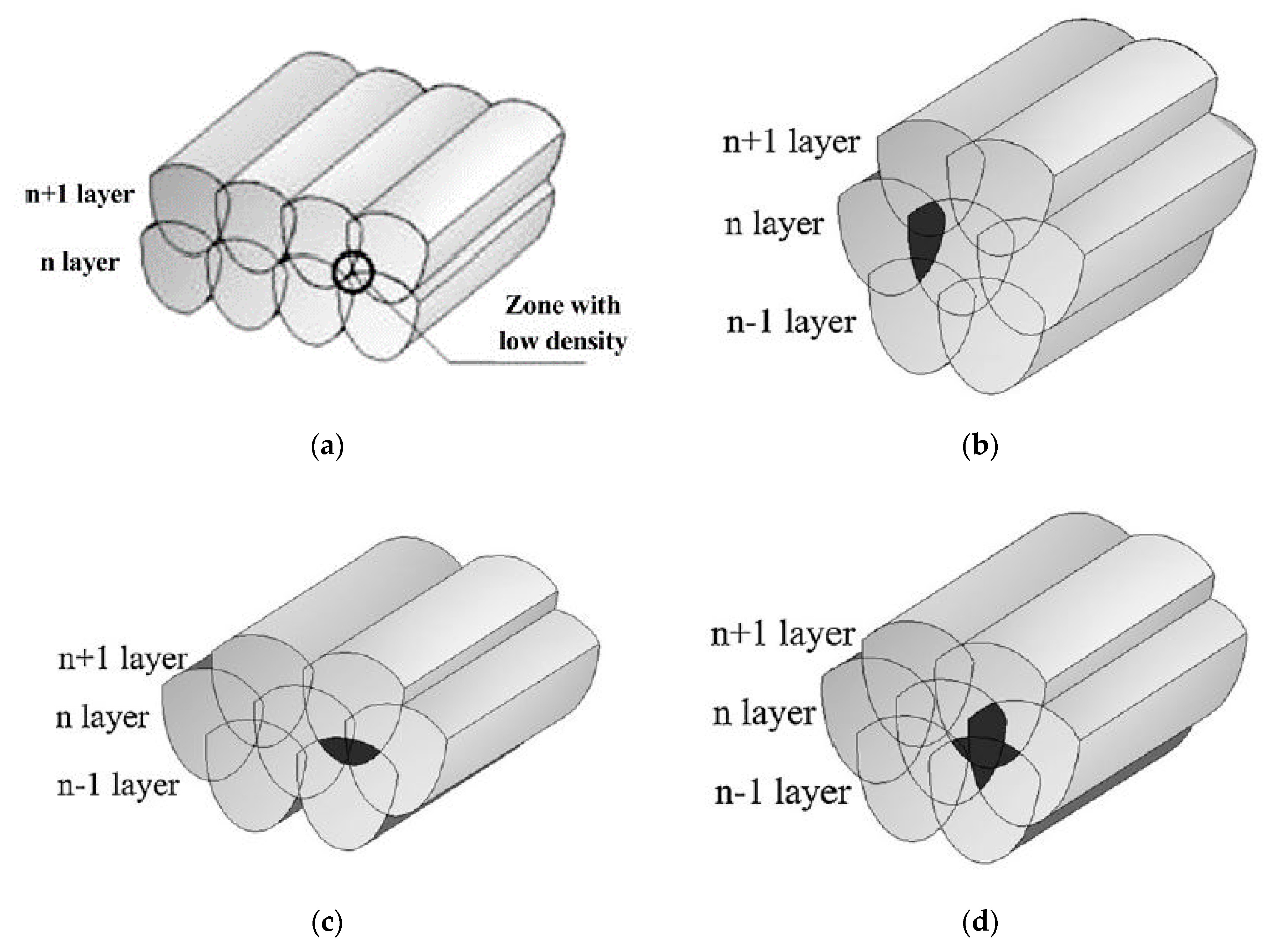
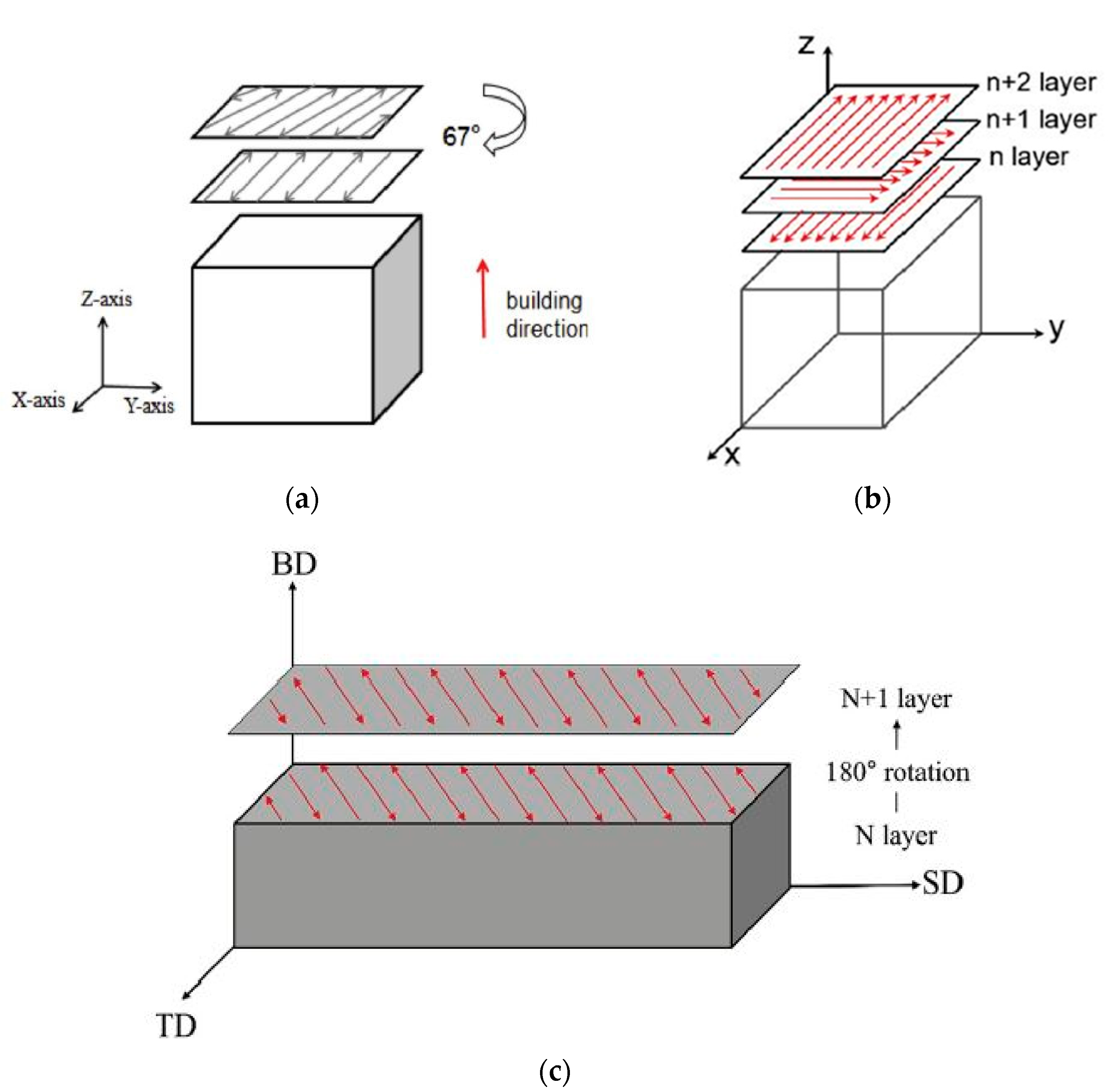
3.3. Effect of Laser Scanning Strategy on the Densification Mechanism

A scanning strategy is a way of building up material layers by systematically depositing the materials. This includes the scanning directions and the arrangement of the scans sequence. The scanning strategy affects the allowed cooling time of fused layers and the overall material properties of the component. It also can be used to control grain orientations and microstructural texture [60]. When the powder fusion process moves from a single bead to a layer, scan spacing in overlapping beads and scanning patterns are some of the essential factors considered. For instance, Su et al. [61] studied the influence of four different scanning strategies and scan spacings (Figure 3) on the building of components with overlapped beads.
The four different scanning patterns and scan spacings resulted in different processing durations, deposited layer thickness and surface features. Pattern 3 produced a wavy surface with superior deposited layer thickness, whereas patterns 1 and 2 showed minimum deposited layer thickness with an undesirable uneven surface finish. Dewidar et al. [62] also tested three scanning strategies, namely standard, diagonal and perimeter scanning for fabricating single layers as depicted in Figure 4. The standard and diagonal scan patterns produced coherent and uniform layers, whereas the perimeter scanning was less successful with distortions during the build.
Another laser scanning strategy employed is the “island” scanning strategy [63,64,65]. In this strategy, the 2D shape of the build is divided into squares forming a checkerboard pattern (Figure 5). Each of the squares (“islands”) is then selectively melted in random order. Within each of the “islands”, simple alternating scan vectors are used with the spacing between these vectors defined as the “scan spacing” and the speed with which the laser spot moves across the surface defined as the “scan speed” [65]. This strategy reduces overall residual stress within the final component [66]. Additionally, this scanning strategy influences the microstructure of the built part and also leads to the formation of several cracks due to the band heating effect of the “islands”. Hence a post-processing treatment is needed to close the cracks.
Furthermore, the inter-layer stagger scanning strategy, also known as the refill strategy, has been utilized by some researchers [67,68,69]. This strategy of scanning has been touted to improve quality, porosity, and bonding strength between layers of built components. Su and Yang [70] utilized this scanning strategy with the aim of attaining a uniform distribution of energy input. The authors identified three track overlapping regimes capable of producing a continuous track. They include the intra-layer overlapping regime, inter-layer overlapping regime and mixed (inter- and intra-) overlapping regime (Figure 6). A high relative density was achieved with the inter-layer overlapping regime when the track space was smaller (<0.2 mm) at the specified process parameters. Similarly, Di et al. [71] also achieved dense and smooth surface parts with scan spacing less than 0.12 mm (i.e., overlapping rate at around 30%) with the inter-layer stagger strategy based on regular- and thin-shaped tracks. Although, Su and Yang [70] focused primarily on track space without giving much attention to other process parameters such as laser power, Di et al. [71] studied and discussed the influence of heat accumulation effect on parameters optimization (scanning power and speed) in a single track, multi-track and multi-layer fabrication of the built part.
Additionally, the inter-layer stagger scanning strategy can repair defects of previously scanned layers by scanning the next layer at an offset in order to scan track overlapping zones [68]. This leads to stronger bonds between layers and fabrication of dense parts.
Usually, the inter-layer stagger strategy is combined with the orthogonal scan strategy to reduce residual stresses and part porosity [69,71,72]. The orthogonal scan strategy involves the scanning of successive layers orthogonal to each other.
Other scan strategies that have been employed in LPBF building of various alloys as illustrated in Figure 7, include the unidirectional or bidirectional scanning strategies. The scanning vectors and consecutive layers in these scan strategies are rotated at 67°, 90° (orthogonal) or 180° (N + 1) with the intention of increasing the homogeneity of energy input.
The re-scanning or re-melting strategy has also been used in the LPBF processing of some materials. As the name suggests, this scanning strategy involves the re-melting of already scanned layers of a component or only for the top surface. The re-scanning parameters may vary from the first scan parameters. Therefore, re-scanning parameters also need to be optimized to be useful during the LPBF process. Kenel et al. [76] demonstrated that re-scanning at a rotation of 90° reduced cracking by a factor of two and was superior to parallel re-scanning in the fabrication of oxide dispersion strengthened γ -TiAl alloys. In addition, Rashid et al. [77] employed a re-scanning strategy where the scan hatch spacing was halved in the fabrication of 17-4PH stainless steel parts. The authors observed an increase in the density of the parts from the re-scanning strategy used. The re-scanning strategy in the LPBF process allows the deposition of a higher energy density compared to a one scan strategy [76]. Many studies have shown the advantages of using the re-scanning strategy, which include improving density [78], enhancing surface quality [78,79], increasing wear resistance [80], and releasing of entrapped gases [50].
In essence, according to Kruth et al. [42], the type of scan strategy used and the geometry of the part to be built influence the induction of internal stresses owing to the temperature gradient. The authors observed that if the area to be scanned is small, a short scan length normally occurs thereby leaving little time for cooling of the surface before the next track is scanned, thus resulting in high temperature. In the case of larger areas, the laser beam travels a longer distance, meaning successively scanned tracks have more time to cool down, resulting in a lower temperature over the scanned area. The lower temperature over the scanned area leads to poor wetting conditions causing a reduction in the material density because of the larger heat sink between the solidified material and the loose powder.

3.4. Effects of the Atmosphere on the LPBF Process

The inert environment used in the LPBF process, just as in the case of most laser processing operations, serves as a shielding gas of the molten metal against mostly oxygen in the atmosphere. The shielding gas in the LPBF process protects metal powders from oxidation and provides a means to remove the ejected powders. Hence, the efficiency of the shielding gas is one of the essential factors in the LPBF process to attain better quality products. Porosity and surface roughness of built parts are two indicators for assessing the quality of products.
The inert gas flow delivery method across the build platform in the LPBF process, as indicated by Ferrar et al. [81] can significantly influence the quality and reproducibility of components across the build area. The porosity of LPBF built parts can be enhanced when the gas flow is highly uniform [81]. Primarily, the gas flow is used to maintain the needed inert atmosphere during processing. However, a secondary function of the inert gas flow is to remove any process by-products such as spatter, condensate, and welding fumes from the path of the laser. These by-products may affect the laser beam properties such as energy, spot diameter and intensity profile at the powder bed [82]. Some modes of gas delivery into the build chamber include an annular flow system that delivers gas in a downward motion circumferentially employed by EOS and a linear gas rail system that directs the gas from one side of the build chamber to the other used by MTT SLM250 and MTT ReaLizer SLM250 [81,82].
Argon (Ar) gas is the most preferred inert gas for the LPBF process. Argon is generally known to be denser than air and as a shielding gas for the LPBF process, capable of stabilizing the molten pool depth and reducing spatter [83]. The depth of the molten pool is significantly affected by heat conduction and the resultant recoil pressure caused by the evaporation of the metal during the LPBF operation. Masmoudi et al. [84] investigated the interaction zone of the laser-powder-atmosphere during the LPBF process. The authors asserted that by adjusting the pressures of the shielding gas, the volume of the evaporated material could be controlled. The authors pointed out that at relatively high pressure, the argon shielding gas narrows the evaporated material into a smaller volume leading to improvement in density and a decrease in propagation speed. Similarly, Dai and Gu [85] reported that the use of Ar as a protective atmosphere in the LPBF process causes the vector direction of the evaporated materials to be typically upwards resulting in a uniform recoil pressure exerted on the melt pool surface. This leads to the improvement of surface quality, morphology, and relatively dense fabricated parts.
In all, the protective atmosphere used for the LPBF process plays a crucial role in the complex hydrodynamics of the molten pool, motion direction and velocity field of the evaporation of materials. These factors, thus, influence the surface quality and densification of components.

3.5. Effects of Powder Characteristics on the LPBF Process

LPBF process parameters, together with the powder energy absorption from the laser irradiation, affect the volumetric energy density (VED) obtainable to heat and melt powders. The ratio of the energy flux absorbed by the material to the energy flux incident upon the material defines the powder absorptance. The absorptivity of a powder layer depends not only on the physical and chemical properties of the powder material but also on granulomorphometry and apparent density of the powder [59]. Powder materials have significantly higher absorptance compared to the bulk materials irrespective of the type of laser. Some examples include A T i   b u l k = 0.3 , A F e   b u l k = 0.36 , A C u   b u l k = 0.02 while A T i   p o w d e r = 0.77 , A F e   p o w d e r = 0.64 and A C u   p o w d e r = 0.59 at λ = 1.06 µm [45,59].
Materials properties such as heat capacity, heat conductivity, latent heat, among others listed in Table 2 significantly influence the LPBF process during the heating, melting and densification of the components.
The effect of powder particle size and distribution is seen of less importance in the LPBF process because all particles interacting with the laser beam melt completely. However, powder size and powder distribution can influence the LPBF process parameters required for a specific material. For instance, Bourell et al. [64] suggested that for smaller sized 316L stainless steel powder, a low laser energy intensity is needed to achieve near fully dense parts (~99%). Additionally, powders with a narrow range of particle size exhibit better flow and produce parts with improved qualities such as surface finish, hardness, and mechanical properties.
The granulomorphometry of powders used for the LPBF process is usually spherical with smooth surfaces and exhibit low surface oxidation. These characteristics allow for good powder flow properties and reduced levels of contamination prior to handling and processing [62].

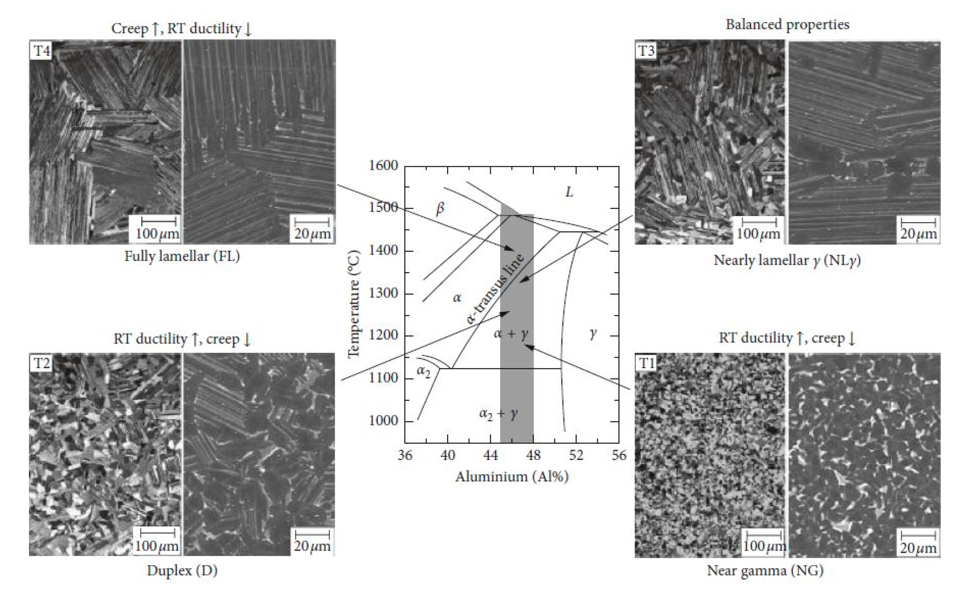
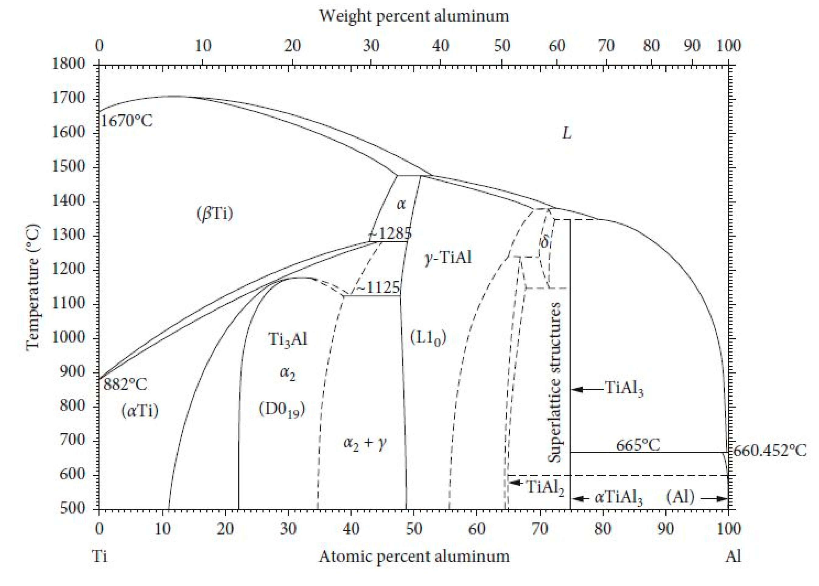
4. LPBF of TiAl Alloys

The LPBF AM technique has been used in fabricating TiAl alloys [76,86,87]. However, the LPBF fabrication of TiAl alloys is still challenging compared to the electron beam melting (EBM) process. EBM has received more focus on the manufacturing of TiAl-based alloys [88,89]. This is mainly because of the high preheating system used in EBM [90]. In the EBM technology, the powder bed remains at high temperature (about 1000 °C) due to the preheating system, which lowers the thermal gradient and residual stress. The decreased thermal gradient and thermal stress lead to the successful building of crack-free TiAl-based alloys [91,92]. In addition, having the powder bed at high temperature during the EBM process is an added advantage since TiAl-based alloys have low room temperature ductility and fracture toughness. TiAl-based alloys exhibit brittle-to-ductile transition at temperatures of 700–800 °C [93]. However, the EBM process lacks dimensional accuracy because of the dimensions of the molten pool [89]. Post-processing treatments such as machining become difficult due to the complex geometries of parts and also culminate in a waste of material [94]. As a result, the current research of AM manufactured TiAl alloys focuses on LPBF because of the high dimensional accuracy of the process.
The successful building of relatively dense (>99%) and crack-free parts of TiAl-based alloys using the LPBF process have been reported [95,96]. The heating of the substrate plate mitigated the effect of residual stress and increased the tendency of achieving crack-free TiAl-based parts. By preheating of the substrate plate and subsequent slow cooling after completion of the LPBF process reduced the temperature gradient between the solidifying layers and the lower parts of the built samples [95] leading to a decrease in residual thermal stresses.
Both LPBF and the EBM manufacturing technologies experience Al loss after processing. Lightweight elements such as Al evaporate during high vacuum processing [92]. The usage of high laser power for the LPBF process is associated with significant overheating, leading to Al evaporation [97]. The evaporation of Al results in compositional variations and inhomogeneous microstructure in the alloy [91]. Moreover, Al loss in TiAl alloys is undesirable since it influences the phases likely to form and the overall properties and performance of the alloy.

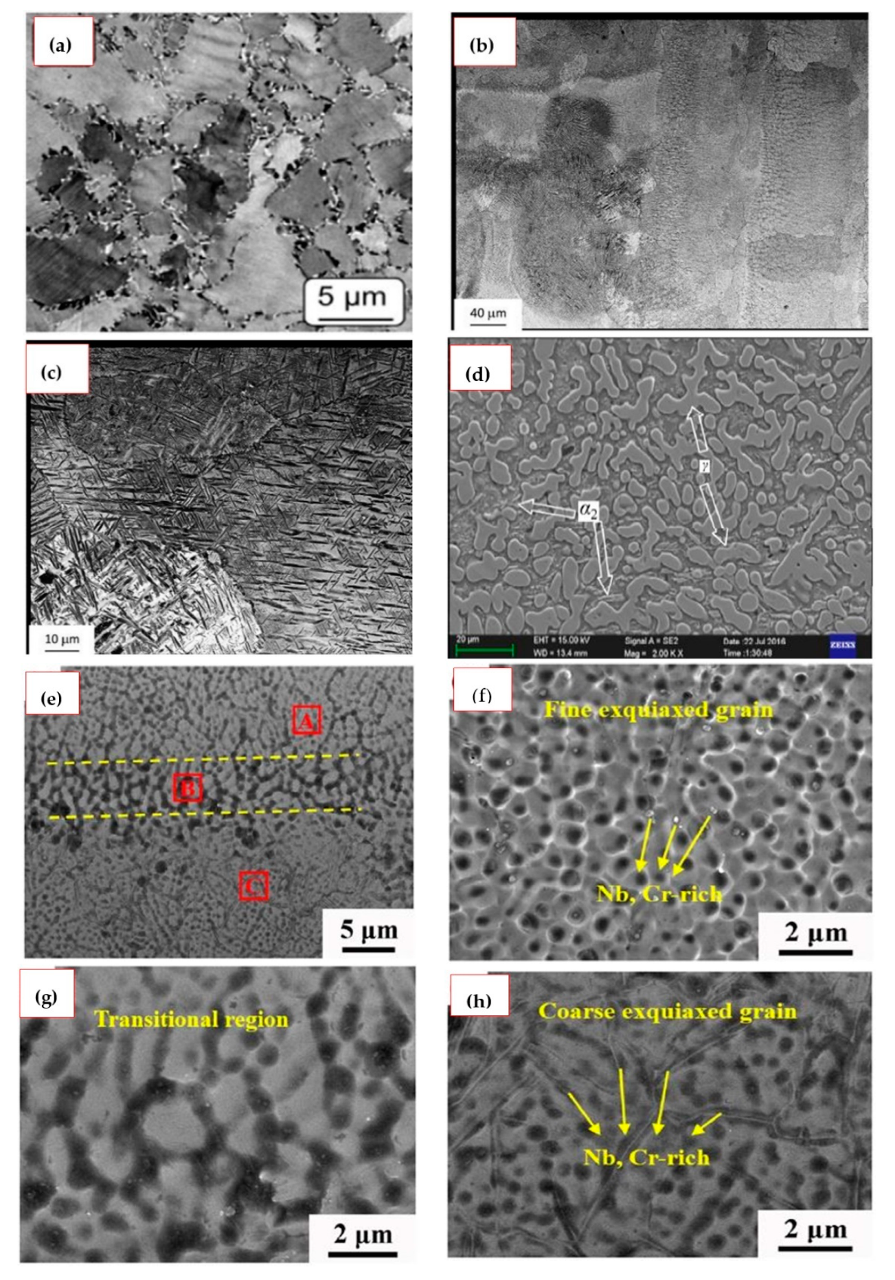
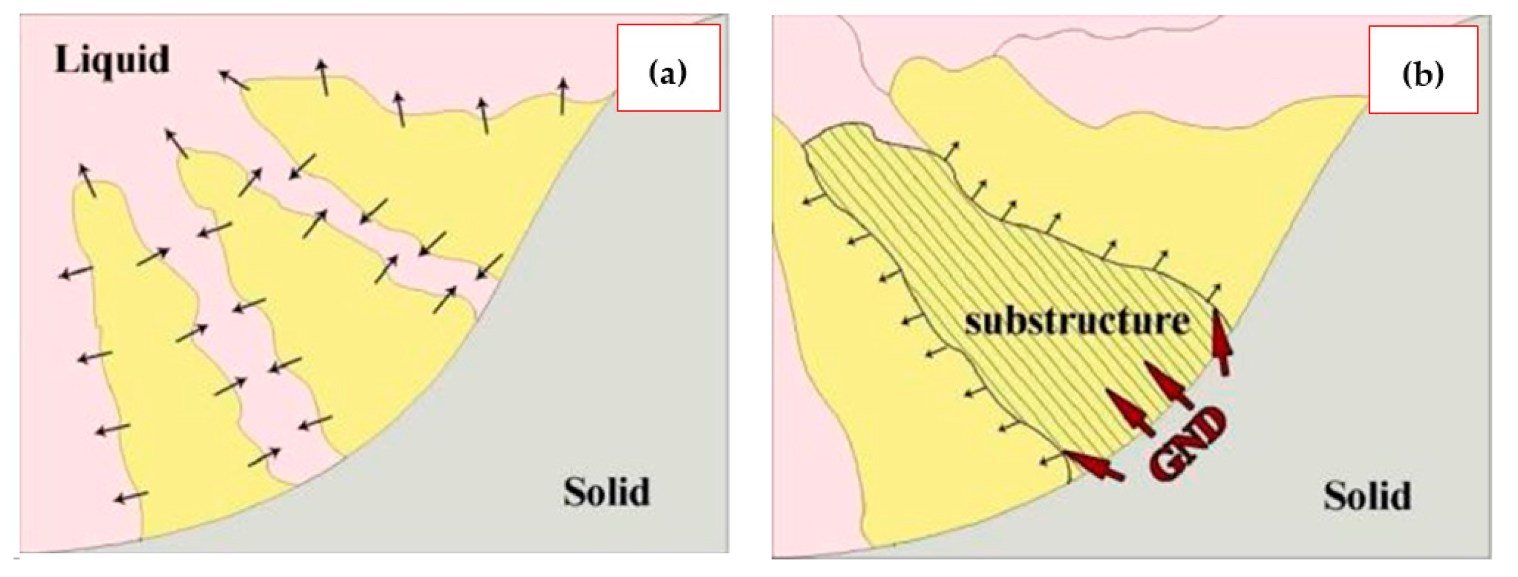
Phase Transformation and Microstructural Evolution of LPBF Built TiAl Alloys

For structural applications, TiAl-based alloys exhibiting dual ( α 2 + γ ) phases are usually preferred. This is because of the flexibility in controlling the proportions and distribution of the formed phases [1]. However, formed grain morphology differs and is highly influenced by the alloy composition, fabrication or heat treatment temperature, cooling rate and stabilization temperature and time. Compared to the γ -phase, the α 2 -phase has a lower density and provides the alloy with good high-temperature strength, impressive creep resistance, higher fracture toughness and crack propagation resistance [3,98]. The γ -phase is responsible for the excellent oxidation resistance and high strength and modulus [3,98].
Four different classifications of microstructures characterise the dual-phase TiAl alloys, as shown in Figure 8. They include the fully lamellar (FL), near lamellar (NL), the duplex microstructures (DM) and the near gamma (NG).
According to the phase diagram in Figure 9, the phase transformation of TiAl alloys during the LPBF process can be summarized as [100,101]:
L L + β β + α α + γ + β α 2 ( T i 3 A l ) + γ ( T i A l ) + B 2
The phase transition during solidification involves a peritectic reaction L + β α , two eutectoid reactions α α 2 + γ and α 2 α 2 + γ , and two ordering transformations of α α 2 and β B 2 . The LPBF process parameters significantly influence these phase formations. For instance, Li et al. [103] with process parameters of 200 W laser power (P), 100 µm scan line hatch spacing (h), 30 µm powder layer thickness (d) and a 90° rotation angle between two consecutive layers scan strategy studied the effect of laser scanning speed (V) on a Ti-45Al-2Cr-5Nb (at.%) alloy. The increase in laser scanning rate results in lower energy density input, which shortens the duration time of the liquid phase and limits the peritectic reaction L + β α . In addition, high laser scanning speed induces the disorder-order transformation of β B 2 and therefore allows the increase in the content of the B 2 phase with increasing scanning speed.
Furthermore, the increase in the laser scanning speed stimulates the eutectoid reaction rates of α α 2 + γ and α 2 α 2 + γ . This is attributed to the sensitive rate of the eutectoid reactions to the cooling rate of the LPBF process. With increasing scanning speed, the content of α 2 phase in the TiAl alloy decrease while the γ and B 2 phases increase. On the one hand, the accelerated eutectoid reaction α α 2 + γ and disorder-order transformation α α 2 due to the high scanning speed means the content of α 2 phase will tend to increase [103]. Conversely, owing to the eutectoid reaction α 2 α 2 + γ and the inhibited peritectic reaction L + β α , the content of the α 2 phase tends to reduce with increasing scanning speed. As the α 2 phase transforms from the single α -phase region, the reduced content of the α dominated phase results in the decreased content of the α 2 phase, which is more than the increased content of α 2 phase by the eutectoid reaction α α 2 + γ and the disorder-order transformation of α α 2 [103]. Additionally, the γ -phase content increase with increasing laser scanning speed because of the stimulated eutectoid reactions α α 2 + γ and α 2 α 2 + γ . The content of the α 2 phase further decreases due to the α 2 α 2 + γ reaction.
Different TiAl alloys have been built using the LPBF technique with varying process parameters and equipment, resulting in varying microstructures, as shown in Table 3. Gussone et al. [104] used an 80 W laser power, a scan speed of 450 mm·s−1, 100 µm hatch spacing and a layer thickness of 30 µm to fabricate a Ti-44.8Al-6Nb-1.0Mo-0.1B (at.%) alloy. With preheating the base plate to 800 °C before building, the alloy exhibited a very fine irregular near-lamellar microstructure ( γ and β / β 0 decorating α 2 / γ colony boundaries) as depicted in Figure 10a. In addition, as shown in Figure 10b,c, a near-lamellar β microstructure was observed perpendicular to the build direction of a beta-solidifying TNM-B1 alloy of composition Ti-28.9Al-9.68Nb-2.26Mo-0.024B wt.% fabricated using LPBF by Löber et al. [96]. The process parameters employed included a 100 W laser power, scanning velocity of 50 mm s−1 for the volume contour, laser power 175 W and scanning velocity of 1000 mm.s−1 for the outer contour, a 300 µm hatch spacing, a layer thickness of 75 µm and a stripe hatching scanning strategy. Ismaeel and Wang [87] used a laser power of 2.0 kW, 3 mm laser beam diameter, scanning speed of 2.5 mm s−1, 30% scan overlap, powder feed rate 3.0 g min−1, an argon flow rate 7.0 L.min−1 and a cross-hatching scan strategy process parameters to study the effect of Nb additions on the microstructure and properties of γ -TiAl based Ti-48Al-2Mn-(3-7)Nb (at.%) alloy built using LPBF. The microstructure of the fabricated alloys evolved from a near full dendrite to a near lamellar structure with increase in Nb additions. The alloys consisted of α 2 (Ti3Al) and γ (TiAl) phases with the morphology of the α 2 (Ti3Al) phase changing from an irregular shape to a fine-lath shape when Nb contents reached 5.0 at.% (see Figure 10d). Li et al. [100] assessed the effect of energy density input on the grain orientation, crystallographic texture and phase evolution in an LPBF-processed Ti-45Al-2Cr-5Nb (at.%) alloy. The process parameters used were a scan speed of 500 mm s−1, a hatch scan spacing of 100 µm, a layer thickness of 20 µm and varying laser power and respective energy densities of 250 W (250 J mm−3), 300 W (300 J mm−3), and 350 W (350 J mm−3). The long bidirectional scanning vectors scanning strategy with a 90° rotation between consecutive layers was used in the study. The built Ti-45Al-2Cr-5Nb (at.%) alloy, from the top view, exhibited equiaxed microstructures and columnar grains from the front or side view. Additionally, three different regions (fine equiaxed grain zone, transitional zone and coarse equiaxed grain zone) were observed across the molten pool as depicted in Figure 10f–h. The moving heat source, increased thermal gradients, and different growth rates over the molten pool explained the occurrence of varying zones.

5. LPBF of HEAs

Currently, there are two groups of HEAs identified and extensively researched for high-temperature use. They include HEAs consisting mostly of 3d transition elements usually Co, Cr, Cu, Fe, Mn, Ni, Ti and V [109]; and refractory HEAs [110] containing refractory elements such as W, Ta, Hf, Nb, Zr and Mo. The most widely studied potential high entropy superalloys (HESAs) are the AlxCrFeCoNi system [111], and the CoCrMnFeNi [112] also referred to as Cantor alloy.
Nickel-based superalloys (NBSAs) are the most used materials for high-temperature applications. Their useful high-temperature properties result from the precipitation of the γ phase (L12 ordered face centred cubic (FCC) phase). However, NBSAs possess a high density (~8.5–9.0 g.cm−3) because of its solvent metal Ni [113]. The possible substitution of Ni with lightweight elements could lead to a reduction in density and cost. The development of HESAs aims to mimic the microstructure of NBSAs. The alloys exhibit a disordered γ phase with an FCC structure mostly serving as a matrix phase and an ordered γ precipitate phase exhibiting an L12 structure. For example, Yeh and co-workers developed HESAs based on non-equimolar AlCoCrFeNiTi system composing of an FCC γ matrix with uniformly dispersed L12 γ particles [114,115]. Manzoni et al. [116] optimized the AlCoCrCuFeNiTi system and achieved a promising Al10Co25Cr8Fe15Ni36Ti6 alloy, which also exhibits microstructural features analogous to the NBSAs. Tsao et al. [117] fabricated two HESAs Ni42.7Al7.8Co20.6Cr12.2Fe11.5Ti5.2 and Ni40.7Al7.8Co20.6Cr12.2Fe11.5Ti7.2, which, after solution heat treatment, formed microstructures like conventional NBSAs.
Four fundamental hypotheses influence the remarkable high-temperature properties of prospect HESAs. They include the high entropy effect, sluggish diffusion effect, severe lattice distortion effect and the “cocktail” effect [118]—also known as rule-of-mixtures [119]. Configurational entropy ( S c o n f ), mixing enthalpy ( H m i x ), atomic size difference (δ) and valence electron configuration (VEC) indicate the probability of phase(s) formation, their relative stability and the final microstructure of the alloys [21]. The sluggish diffusion kinetics in HESA promote the formation of nanostructures, high-temperature strength and an impressive high-temperature structural stability [120]. Additionally, unlike conventional alloys, HEAs are baseless; thus, the different atomic sizes of the elements making up the compositionally complex alloys lead to lattice distortions. The attendant lattice strains increase the strength and hardness of the alloys [120]. On the other hand, the cocktail effect highlights the possibilities of attaining exceptional HESA properties through the synergistic mixture and interactions of the unique attributes of the individual elements composing the alloy [118].

Microstructures of LPBF-Built HEAs

The LPBF AM process has been used in the fabrication of different potential HESAs [121,122,123,124]. Most of these LPBF fabricated alloys, as summarized in Table 4, exhibit an FCC crystal structure after processing.
The LPBF produced microstructures of these potential HESAs are usually hierarchical. The hierarchical microstructures are achieved because of the nature of fabrication of the alloys, which involve the layer-by-layer deposition, connection of melt pools, rapid cooling rate, and non-equilibrium solidification [143]. The built LPBF-HEA microstructures are typically mixed and consist of hierarchical features such as melt pools, columnar grains, cellular structures, dislocations and precipitates [143]. The process parameter optimization affects the hierarchical heterogeneous microstructures. The laser beam diameter and powder layer thickness closely correspond to the width and height of formed melt pools [125]. The melt pools are typically semi-elliptical and emerge from the radial flow of heat away from the centre [125]. Furthermore, as an inherent feature of LPBF processing, columnar grains form along the build direction. The preferred grain orientation in the build direction results from the remelting under the repeated deposition of metal [27]. As observed by Piglione et al. [123] the preferred growth direction tend to align with the direction of maximum heat flux in the melt pool region (i.e., the direction perpendicular to the fusion line) as depicted in Figure 11. Existing grains then grow epitaxially owing to the fast cooling rates and induces columnar grain growth, and grain selection through competitive growth [123]. The effects of the melt pool shape and temperature gradient on crystallographic texture can be influenced by the LPBF processing parameters. In this regard, Peyrouzet et al. [139] deduced that stronger texture or change in preferred grain orientation would develop toward the build direction when a bidirectional scanning strategy with 0° or 90° rotation between successive layers is used instead of a 67° rotation and/or by increasing of the scanning laser power. The authors further argued that the use of unidirectional scanning strategy with a 67° rotation does not favour the zigzag solidification pattern and leads to the formation of randomly oriented grains in the plane perpendicular to the build direction.
Also, the formation of subgrain structures in the columnar grains characterises the hierarchical microstructure of LPBF-built HEAs [125,144]. Figure 12 illustrates the formation of substructures. The morphology of these subgrains are usually columnar or cellular-type [27] (see Figure 11). AM fabricated materials are known to exhibit a distinct cell structure, and the cell size is known to vary according to process conditions [75]. The shape of the cell structure is formed due to either elemental segregation or dislocation network as exemplified in AlCrCuFeNi [73,74] and AlCrCuFeNix (x = 2.0, 2.5, 2.75, 3.0) [137] studied alloys.
Inevitably, LPBF-processed metals are associated with high-density dislocation owing to the complex thermal cycle with cooling rates exceeding 106 K·s−1 [27]. High density dislocations are a common nanostructure in LPBF-processed HEAs, such as CoCrFeNi [129,130], CoCrFeMnNi [128,144], (C, Si)-containing CoCrFeNi [133,134,135,136], Al0.3CoCrFeNi [139], and AlCrFeNiV [138]. The formation of dislocations in the LPBF-built components is attributed to the vacancy energies difference between the solid and liquid states. The vacancy energy is low in the liquid molten pool, and vacancies are abundant. On the other hand, regarding the solid-state, the vacancy energy is high and gradually occupied during solidification. However, the rapid solidification process in LPBF coupled with the sluggish diffusion in HEAs both prevent vacancies from being filled. Therefore, many unoccupied vacancies remain in the built material, which then merges into massive dislocations [129,145]. Moreover, formed substructures are closely related to dislocation density. The grain boundaries of these substructures are made up of dislocation walls and form dislocation networks as shown in Figure 13. Within some of these substructures, there exist almost no dislocations whereas others contain high density dislocations. Increased vacancy concentration and the presence of large thermal residual stresses from the LPBF process lead to the accumulation of dislocation pile-ups which further increases dislocation density [27,128,129] (see Figure 13).
Precipitates are another subgrains feature identified with LPBF-processed HEAs [124,132,138,141]. It can be surmised that since the LPBF process culminates in grain refinement, together with the emergence of substructures and dislocations, there exist numerous grain boundaries with high energy levels [27]. The high energy levels thus enhance atomic diffusion at the grain boundaries (which serve as diffusion channels) and lead to the solid-state transition of precipitates [128]. The rapid solidification conditions of the LPBF process further enables precipitations. Yao et al. [138] observed nano precipitates of the L12 (~0.207 nm) phase in LPBF-processed AlCrFeNiV. A mixture of precipitates of Mn-rich oxide and sulfide and Cr-rich with size ranging 30–70 nm were detected by Park et al. [133] at the subgrain boundaries in LPBF-processed 1%C-CoCrFeMnNi. In LPBFed equiatomic AlCrCuFeNi HEA alloy, Luo et al. [74] found nano-scale chain-like and granular shaped Cu-rich phase precipitates at the high angle and low angle grain boundaries (HAGB and LAGB), respectively. In addition, alternating sinuous ribbon-shaped precipitates containing B2 and A2 phase were also observed at the subgrain boundaries.

6. Mechanical Properties of LPBF-Processed TiAl-Based Alloys and HEAs

Table 5 shows a compilation of published studies on the mechanical properties of LPBF-processed TiAl-based alloys. It is noted that most of the studies were on hardness (micro or nano), compression and tensile properties evaluation at room temperature. Till date, the long-standing objective of TiAl-based alloys has been to attain balanced mechanical properties at room and elevated temperatures. Microalloying and grain refinement through rapid solidification processing route are two means employed in enhancing the mechanical properties of TiAl-based alloys. Ismaeel and Wang [87] studied the effect of Nb addition on the mechanical properties of LPBFed γ -TiAl alloys. The alloy with the highest Nb content (7 at.%) showed the best mechanical properties owing to the increased amount of the α2 (Ti3Al) phase. The refined grains observed, together with the increased volume fraction of the α2 phase, can relieve stress concentrated at the grain boundaries and decrease the tendency of the development of crack branches [146]. Additionally, the dissolution of increased Nb quantities in the γ-TiAl phase leads to the increment of critical resolved shear stress and reduction of super-lattice intrinsic stacking fault. Thus, improving the strength and ductility of the alloy [147]. Furthermore, the mechanical properties of TiAl-based alloys can be improved by decreasing the thickness of the α2 + γ lamellar. Doubenskaia et al. [33] achieved lamellar thickness 2–4 times smaller in the dendrite zone and 5–10 times smaller in the interdendritic zone than the typical lamellar thickness of directional solidification casting using LPBF to fabricate Ti-48Al-2Cr-2Nb (at.%) alloy. This, therefore, demonstrate that LPBF is a promising technology capable of manufacturing TiAl-based alloys with enhanced mechanical properties. The precipitation of the B2 in LPBFed TiAl-based alloys have also been reported to increase hardness [101,103]. The B2 phase is well known to be harder than the α2 and γ phases.
A compilation of findings on mechanical properties of LPBF-processed HEAs is presented in Table 6. The CoCrFeNi HEA system which forms the base of most studied 3d transition HEAs has been processed using LPBF. Brif et al. [122] showed that LPBF-processed CoCrFeNi HEA could achieve mechanical properties matching established alloys such as stainless steel. The LPBFed CoCrFeNi exhibited yield strength (600 MPa) more than three times that processed using conventional melting and casting. Grain refinement owing to the large thermal gradients and rapid solidification of the LPBF account for the superior mechanical properties. The addition of C to the LPBFed CoCrFeNi HEA enhanced its yield strength from 600 MPa to ~638 MPa, and ultimate tensile strength from 745 MPa to ~795 MPa [134]. Solid-solution, dislocation and precipitation strengthening mechanisms contributed to the improvement of the yield strength of the HEA. The columnar and cellular structures formed dislocation networks that impeded dislocation mobility and led to dislocation storage. In addition, nanosized uniformly distributed carbides and segregated elements pinned dislocation networks. The slight misorientation between adjacent cells promoted the stability of dislocation networks [148]. Hence, although the impeded dislocations across these networks increased in strain, the size and morphology of the dislocation networks retained its original state, leading to stable and continuous strengthening. Lastly, the nanosized carbide precipitates (M23C6) uniformly distributed at the dislocation networks and grain boundaries, culminated in improving strength by impeding dislocation mobility.
The addition of Mn to CoCrFeNi to form CoCrFeMnNi is the most studied LPBFed HEA [75,121,126,127,128,144]. The ultra-fine grain size and formation of a σ phase improve mechanical properties of LPBFed CoCrFeMnNi.
Moreover, significant improvement in mechanical properties of LPBFed CoCrFeNi and CoCrFeMnNi HEAs containing Al, Ti and C have been reported [131,132,133,139]. The addition of Al promotes the formation of the BCC phase and leads to improvement of mechanical properties [140,141,142]. Grain refinement, dislocation hardening and precipitation hardening account for the improvement in strength in the Al and C containing HEAs.
Laser power, scanning speed, hatch spacing, and powder layer thickness are functions of the VED. These primary processing parameters influence HEA densification, microstructures, and mechanical performance. The thermal gradient (G) over the molten pool depends on energy input from the combination of laser power and scan speed. In addition, the scan speed determines the growth rate (R) of the solid-liquid interface [27]. High energy input deteriorates microstructure and decreases strength. Moreover, G/R and G*R define the solidified microstructures’ morphology and size, respectively. A lower ratio of G/R means grain morphology is equiaxed, whereas a higher cooling rate (G*R) indicates a finer microstructure [149]. Porosity minimizes with small hatch spacing and layer thickness. The LPBF fabrication of CoCrFeNi HEA with a small layer thickness of 20 µm showed better tensile properties compared to a 50 µm layer thickness [122]. This was because of internal and incomplete fusion defects caused by insufficient melting of the thicker layers. Therefore, increasing VED improves density, which means mechanical properties also enhance [128].
Another observation was the influence of post-processing treatments on the mechanical properties of LPBFed HEAs. The annealing heat treatment process increased ductility and impact toughness but decreased hardness and strength of LPBFed CoCrFeNi [129]. The annealing process relieved residual stresses, decomposed dislocation networks and facilitated recrystallisation, resulting in strain hardening and improved the ductility and toughness. Conversely, solution treatment enhanced yield and tensile strength of LPBFed CoCrFeNiTi [131], owing to the square root of the product of grain size (radius) and volume fraction of the Ni and Ti ordered precipitates. In addition, the application of HIP improves densification and eliminates metallurgical defects. Li et al. [128] obtained nearly 10% ultimate tensile strength increment of LPBFed CoCrFeMnNi alloy after HIP treatment. However, at the expense of elongation.
In all, it is evident that more research is needed before the successful implementation of LPBFed TiAl-based alloys and HEAs. As potential candidates for high-temperature applications, it is crucial that elevated temperature mechanical tests such as creep are carried out on LPBFed TiAl alloys. Additionally, the effect of thermal and microstructural stability of LPBFed HEAs will add more knowledge to the field. Since increasing density improves mechanical properties, it is imperative that attaining crack- and pore-LPBFed TiAl alloys and HEAs will further improve mechanical properties.

7. Present Research Progress and Future Studies

Presently, the main challenge in the LPBF building of TiAl alloys has to do with the crack sensitivity of TiAl-based alloys. So far, two promising approaches have been studied to mitigate the intrinsic high thermal gradient and residual stresses associated with LPBF. Preheating of the substrate metal before building has been applied to the LPBF process. The preheating of the substrate reduces the temperature gradient between the solidifying layers and the lower parts of the built samples [95], leading to a decrease in residual thermal stresses. The use of substrate heating techniques such as resistive heaters and induction heating circuit enable the base plate to reach higher temperatures between 800–1000 °C. The incorporation of preheating systems capable of attaining high temperatures promotes increased productivity. This may be ascribed to the energy added to the process, enhanced optical absorptivity at higher temperatures and decrease of residual thermal stresses. In a very recent study, Caprio et al. [90] developed a novel preheating system as shown in Figure 14, with the ability to provide and constantly maintaining high preheating throughout the build of crack prone materials such as TiAl-based alloys. The system allows control of the cooling rate to prevent crack formation. With a preheat temperature of 800 °C, a Ti-48Al-2Cr-2Nb (at.%) component was successful fabricated. The crack formation was suppressed, and apparent density exceeded 99%. It is evident, as demonstrated by Caprio et al. [90] that the manufacturing objective of crack- and pore-free TiAl components via LPBF is gradually maturing and becoming a reality. However, the extent to which powder quality impacts on sintering behaviour when high-temperature preheating (1000 °C) is employed remains scope for future studies [96].
Alternatively, the use of TiAl-based alloys with high additions of β -stabilizing elements such as Nb and Mo could be used in fabricating crack-free TiAl alloys using LPBF. These new class of alloys are termed TNM and TNB and may include small addition of B and C. The addition of β -stabilizing elements help ensure solidification during build occurs through the β -phase. The introduction of the β -phase in TiAl alloys during processing help suppress cracks owing to their ductility. Additionally, slow diffusivity and deformation accommodation characterise β -stabilizing elements and the β -phase, respectively. Hence serving as a means in the manufacturing of crack-free TiAl-based parts. TNM alloys, under non-equilibrium conditions, have been reported to show reduced segregation behaviour involving high cooling rates [152,153]. Moreover, in most TiAl alloys, the Nb content is lower to avoid the β / β 0 from stabilising. Using post heat treatment, the β -phase can be eliminated from the final microstructure of the alloy after the LPBF process. Examples of some TNM alloys fabricated by LPBF are shown in Table 3.
It is clear from this review that most studies on LPBFed HEAs are usually focused on optimization of process parameters, build orientation effects, microstructure characterization and mechanical properties evaluation. Improving the properties and performance of HEAs rests on the careful optimization and implementation of tailored microstructures through controlled processing and appropriate alloy manipulations that can promote and stabilize new microstructures. Grain refinement, the formation of substructures such as phase precipitates and increased dislocation densities characterise the LPBF process. These features improve the mechanical properties of LPBFed HEAs exceeding that of conventional methods. Nonetheless, associated LPBF processing defects such as porosity and cracks still pose a challenge. Research on understanding these defects and ways to circumvent or suppress them during build deserves more attention.
Furthermore, the AlxCrFeCoNi and CoCrMnFeNi series alloys have received the most attention in the fabrication of LPBF HEAs for potential high-temperature applications. However, these alloys have relatively high densities. The prospect of using LPBF to fabricate lightweight HEAs have not been reported. Weight-saving alloys in the transport, energy and aviation industries could reduce cost, enhance the efficiency of advanced engines, and decrease emissions. Therefore, there is a need for research on LPBF of lightweight HEAs for significant industrial applications.
Also, a future research focus for LPBFed HEAs could be in applications of energy storage, functional electronic devices, chemical and electromagnetic shielding. These areas are in constant search for high-performance materials with exceptional functional properties. There are no or few studies on LPBF-processed HEAs reported in this field. Thus, research on the viability of LPBF-processed components in meeting the demands of these fields could be invaluable.

Author Contributions

Conceptualization, writing—original draft preparation, P.V.C.; writing—review and editing, visualization, P.V.C., R.A.N., O.T.O. and W.R.M.; supervision, W.R.M. All authors have read and agreed to the published version of the manuscript.

Funding

This research received no external funding, and the APC was funded by Vaal University of Technology (South Africa).

Acknowledgments

The authors would like to thank and acknowledge the DSI-funded Titanium Centre of Competence (TiCoC), South Africa for financial support.

Conflicts of Interest

The authors declare no conflict of interest.

References

  1. Appel, F.; Oehring, M. γ-titanium aluminide alloys: Alloy design and properties. In Titanium and Titanium Alloys. Fundamentals and Applications; Leyens, C., Peters, M., Eds.; WILEY-VCH Verlag GmbH & Co. KGaA, Weinheim: Cologne, Germany, 2003; pp. 89–93. [Google Scholar]
  2. Bewlay, B.; Nag, S.; Suzuki, A.; Weimer, M. TiAl alloys in commercial aircraft engines. Mater. High Temp. 2016, 33, 549–559. [Google Scholar] [CrossRef]
  3. Kothari, K.; Radhakrishnan, R.; Wereley, N.M. Advances in gamma titanium aluminides and their manufacturing techniques. Prog. Aerosp. Sci. 2012, 55, 1–16. [Google Scholar] [CrossRef]
  4. Yeh, J.W.; Chen, S.K.; Lin, S.J.; Gan, J.Y.; Chin, T.S.; Shun, T.T.; Tsau, C.H.; Chang, S.Y. Nanostructured high-entropy alloys with multiple principal elements: Novel alloy design concepts and outcomes. Adv. Eng. Mater. 2004, 6, 299–303. [Google Scholar] [CrossRef]
  5. Senkov, O.; Scott, J.; Senkova, S.; Meisenkothen, F.; Miracle, D.; Woodward, C. Microstructure and elevated temperature properties of a refractory TaNbHfZrTi alloy. J. Mater. Sci. 2012, 47, 4062–4074. [Google Scholar] [CrossRef]
  6. Lu, Y.; Dong, Y.; Guo, S.; Jiang, L.; Kang, H.; Wang, T.; Wen, B.; Wang, Z.; Jie, J.; Cao, Z. A promising new class of high-temperature alloys: Eutectic high-entropy alloys. Sci. Rep. 2014, 4, 6200. [Google Scholar] [CrossRef] [PubMed]
  7. Ding, Q.; Zhang, Y.; Chen, X.; Fu, X.; Chen, D.; Chen, S.; Gu, L.; Wei, F.; Bei, H.; Gao, Y. Tuning element distribution, structure and properties by composition in high-entropy alloys. Nature 2019, 574, 223–227. [Google Scholar] [CrossRef]
  8. Chen, J.; Niu, P.; Liu, Y.; Lu, Y.; Wang, X.; Peng, Y.; Liu, J. Effect of Zr content on microstructure and mechanical properties of AlCoCrFeNi high entropy alloy. Mater. Des. 2016, 94, 39–44. [Google Scholar] [CrossRef]
  9. Chuang, M.-H.; Tsai, M.-H.; Wang, W.-R.; Lin, S.-J.; Yeh, J.-W. Microstructure and wear behavior of AlxCo1. 5CrFeNi1. 5Tiy high-entropy alloys. Acta Mater. 2011, 59, 6308–6317. [Google Scholar] [CrossRef]
  10. Hemphill, M.A.; Yuan, T.; Wang, G.; Yeh, J.; Tsai, C.; Chuang, A.; Liaw, P. Fatigue behavior of Al0.5CoCrCuFeNi high entropy alloys. Acta Mater. 2012, 60, 5723–5734. [Google Scholar] [CrossRef]
  11. Feng, X.; Zhang, J.; Xia, Z.; Fu, W.; Wu, K.; Liu, G.; Sun, J. Stable nanocrystalline NbMoTaW high entropy alloy thin films with excellent mechanical and electrical properties. Mater. Lett. 2018, 210, 84–87. [Google Scholar] [CrossRef]
  12. Mishra, R.K.; Shahi, R.R. Phase evolution and magnetic characteristics of TiFeNiCr and TiFeNiCrM (M = Mn, Co) high entropy alloys. J. Magn. Magn. Mater. 2017, 442, 218–223. [Google Scholar] [CrossRef]
  13. Kai, W.; Li, C.; Cheng, F.; Chu, K.; Huang, R.; Tsay, L.; Kai, J. Air-oxidation of FeCoNiCr-based quinary high-entropy alloys at 700–900 °C. Corros. Sci. 2017, 121, 116–125. [Google Scholar] [CrossRef]
  14. Kumar, N.; Fusco, M.; Komarasamy, M.; Mishra, R.; Bourham, M.; Murty, K. Understanding effect of 3.5 wt.% NaCl on the corrosion of Al0.1CoCrFeNi high-entropy alloy. J. Nucl. Mater. 2017, 495, 154–163. [Google Scholar] [CrossRef]
  15. Xie, P.; Yao, Y.; Huang, Z.; Liu, Z.; Zhang, J.; Li, T.; Wang, G.; Shahbazian-Yassar, R.; Hu, L.; Wang, C. Highly efficient decomposition of ammonia using high-entropy alloy catalysts. Nat. Commun. 2019, 10, 1–12. [Google Scholar] [CrossRef] [PubMed] [Green Version]
  16. Edalati, P.; Floriano, R.; Mohammadi, A.; Li, Y.; Zepon, G.; Li, H.-W.; Edalati, K. Reversible room temperature hydrogen storage in high-entropy alloy TiZrCrMnFeNi. Scr. Mater. 2020, 178, 387–390. [Google Scholar] [CrossRef]
  17. Sahlberg, M.; Karlsson, D.; Zlotea, C.; Jansson, U. Superior hydrogen storage in high entropy alloys. Sci. Rep. 2016, 6, 36770. [Google Scholar] [CrossRef] [Green Version]
  18. Kunce, I.; Polanski, M.; Bystrzycki, J. Structure and hydrogen storage properties of a high entropy ZrTiVCrFeNi alloy synthesized using Laser Engineered Net Shaping (LENS). Int. J. Hydrog. Energy 2013, 38, 12180–12189. [Google Scholar] [CrossRef]
  19. Sogabe, R.; Goto, Y.; Mizuguchi, Y. Superconductivity in REO0. 5F0. 5BiS2 with high-entropy-alloy-type blocking layers. Appl. Phys. Express 2018, 11, 053102. [Google Scholar] [CrossRef]
  20. Chaudhary, V.; Borkar, T.; Mikler, C.; Gwalani, B.; Choudhuri, D.; Soni, V.; Alam, T.; Ramanujan, R.; Banerjee, R. Additively Manufactured Functionally Graded FeNi based High Entropy Magnetic Alloys. In Proceedings of the 2018 IEEE International Magnetics Conference (INTERMAG), Singapore, 23–27 April 2018; p. 1. [Google Scholar]
  21. Miracle, D.B.; Senkov, O.N. A critical review of high entropy alloys and related concepts. Acta Mater. 2017, 122, 448–511. [Google Scholar] [CrossRef] [Green Version]
  22. Güther, V.; Allen, M.; Klose, J.; Clemens, H. Metallurgical processing of titanium aluminides on industrial scale. Intermetallics 2018, 103, 12–22. [Google Scholar] [CrossRef]
  23. Wang, P.; Huang, P.; Ng, F.L.; Sin, W.J.; Lu, S.; Nai, M.L.S.; Dong, Z.; Wei, J. Additively manufactured CoCrFeNiMn high-entropy alloy via pre-alloyed powder. Mater. Des. 2019, 168, 107576. [Google Scholar] [CrossRef]
  24. Torralba, J.; Alvaredo, P.; García-Junceda, A. High-entropy alloys fabricated via powder metallurgy. A critical review. Powder Met. 2019, 62, 84–114. [Google Scholar] [CrossRef]
  25. Hsu, C.-Y.; Yeh, J.-W.; Chen, S.-K.; Shun, T.-T. Wear resistance and high-temperature compression strength of Fcc CuCoNiCrAl 0.5 Fe alloy with boron addition. MMTA 2004, 35, 1465–1469. [Google Scholar] [CrossRef]
  26. Frazier, W.E. Metal additive manufacturing: A review. J. Mater. Eng. Perform. 2014, 23, 1917–1928. [Google Scholar] [CrossRef]
  27. Zhang, C.; Zhu, J.; Zheng, H.; Li, H.; Liu, S.; Cheng, G.J. A review on microstructures and properties of high entropy alloys manufactured by selective laser melting. Int. J. Extrem. Manuf. 2020, 2, 032003. [Google Scholar] [CrossRef]
  28. Smith, M.; Cantwell, W.; Guan, Z.; Tsopanos, S.; Theobald, M.; Nurick, G.; Langdon, G. The quasi-static and blast response of steel lattice structures. J. Sandw. Struct. Mater. 2011, 13, 479–501. [Google Scholar] [CrossRef]
  29. Ushijima, K.; Cantwell, W.; Mines, R.; Tsopanos, S.; Smith, M. An investigation into the compressive properties of stainless steel micro-lattice structures. J. Sandw. Struct. Mater. 2011, 13, 303–329. [Google Scholar] [CrossRef]
  30. Mellor, S.; Hao, L.; Zhang, D. Additive manufacturing: A framework for implementation. Int. J. Prod. Econ. 2014, 149, 194–201. [Google Scholar] [CrossRef] [Green Version]
  31. Attar, H.; Ehtemam-Haghighi, S.; Kent, D.; Dargusch, M.S. Recent developments and opportunities in additive manufacturing of titanium-based matrix composites: A review. Int. J. Mach. Tools Manuf. 2018, 133, 85–102. [Google Scholar] [CrossRef]
  32. Kruth, J.-P.; Badrossamay, M.; Yasa, E.; Deckers, J.; Thijs, L.; Van Humbeeck, J. Part and material properties in selective laser melting of metals. In Proceedings of the 16th International Symposium on Electromachining, Shanghai, China, 19–23 April 2010; pp. 1–12. [Google Scholar]
  33. Doubenskaia, M.; Domashenkov, A.; Smurov, I.; Petrovskiy, P. Study of selective laser melting of intermetallic TiAl powder using integral analysis. Int. J. Mach. Tools Manuf. 2018, 129, 1–14. [Google Scholar] [CrossRef]
  34. Griffiths, V.; Scanlan, J.P.; Eres, M.H.; Martinez-Sykora, A.; Chinchapatnam, P. Cost-driven build orientation and bin packing of parts in selective laser melting (SLM). Eur. J. Oper. Res. 2019, 273, 334–352. [Google Scholar] [CrossRef] [Green Version]
  35. Bremen, S.; Meiners, W.; Diatlov, A. Selective laser melting: A manufacturing technology for the future? Laser Tech. J. 2012, 9, 33–38. [Google Scholar] [CrossRef]
  36. Kruth, J.-P.; Levy, G.; Klocke, F.; Childs, T. Consolidation phenomena in laser and powder-bed based layered manufacturing. CIRP Ann. 2007, 56, 730–759. [Google Scholar] [CrossRef]
  37. Santos, E.C.; Shiomi, M.; Osakada, K.; Laoui, T. Rapid manufacturing of metal components by laser forming. Int. J. Mach. Tools Manuf. 2006, 46, 1459–1468. [Google Scholar] [CrossRef]
  38. Das, S. Physical aspects of process control in selective laser sintering of metals. Adv. Eng. Mater. 2003, 5, 701–711. [Google Scholar] [CrossRef]
  39. Körner, C.; Bauereiß, A.; Attar, E. Fundamental consolidation mechanisms during selective beam melting of powders. Model. Simul. Mater. Sci. Eng. 2013, 21, 085011. [Google Scholar] [CrossRef] [Green Version]
  40. Kruth, J.P.; Mercelis, P.; Van Vaerenbergh, J.; Froyen, L.; Rombouts, M. Binding mechanisms in selective laser sintering and selective laser melting. Rapid Prototyp. J. 2005, 11, 26–36. [Google Scholar] [CrossRef] [Green Version]
  41. Olakanmi, E.O.; Cochrane, R.; Dalgarno, K. A review on selective laser sintering/melting (SLS/SLM) of aluminium alloy powders: Processing, microstructure, and properties. Prog. Mater. Sci. 2015, 74, 401–477. [Google Scholar] [CrossRef]
  42. Kruth, J.P.; Froyen, L.; van Vaerenbergh, J.; Mercelis, P.; Rombouts, M.; Lauwers, B. Selective laser melting of iron-based powder. J. Mater. Process. Technol. 2004, 149, 616–622. [Google Scholar] [CrossRef]
  43. Yap, C.Y.; Chua, C.K.; Dong, Z.L.; Liu, Z.H.; Zhang, D.Q.; Loh, L.E.; Sing, S.L. Review of selective laser melting: Materials and applications. Appl. Phys. Rev. 2015, 2, 041101. [Google Scholar] [CrossRef]
  44. Lauwers, B.; Kruth, J.-P.; Bonse, J.; Oorts, S.; Froyen, L. Comparison between Nd: YAG and CO2 lasers for use with selective laser sintering of metal powders. Proc. Photomec’99 1999, 1999, 165–173. [Google Scholar]
  45. Tolochko, N.K.; Khlopkov, Y.V.; Mozzharov, S.E.; Ignatiev, M.B.; Laoui, T.; Titov, V.I. Absorptance of powder materials suitable for laser sintering. Rapid Prototyp. J. 2000, 6, 155–161. [Google Scholar] [CrossRef]
  46. Lee, H.; Lim, C.H.J.; Low, M.J.; Tham, N.; Murukeshan, V.M.; Kim, Y.-J. Lasers in additive manufacturing: A review. Int. J. Precis. Eng. Manuf. Green Technol. 2017, 4, 307–322. [Google Scholar] [CrossRef]
  47. Majumdar, J.D.; Manna, I. Laser-Assisted Fabrication of Materials; Springer Science & Business Media: Berlin/Heidelberg, Germany, 2012. [Google Scholar]
  48. Cao, X.; Wallace, W.; Poon, C.; Immarigeon, J.-P. Research and progress in laser welding of wrought aluminum alloys. I. Laser welding processes. Mater. Manuf. Process. 2003, 18, 1–22. [Google Scholar] [CrossRef]
  49. Mueller, R.; Gu, H.; Ferguson, N. Nd: YAG Laser Welding for Automotive Manufacturing Applications; Technical Paper; SAE: Warrendale, PA, USA, 1999. [Google Scholar]
  50. Morgan, R.H.; Papworth, A.J.; Sutcliffe, C.; Fox, P.; O’Neill, W. High density net shape components by direct laser re-melting of single-phase powders. J. Mater. Sci. 2002, 37, 3093–3100. [Google Scholar] [CrossRef]
  51. Steen, W.M.; Mazumder, J. Laser Material Processing; Springer Science & Business Media: Berlin/Heidelberg, Germany, 2010. [Google Scholar]
  52. Kong, F.; Gu, G.; Hawkins, T.W.; Parsons, J.; Jones, M.; Dunn, C.; Kalichevsky-Dong, M.T.; Wei, K.; Samson, B.; Dong, L. Flat-top mode from a 50 µm-core Yb-doped leakage channel fiber. Opt. Express 2013, 21, 32371–32376. [Google Scholar] [CrossRef]
  53. Sezerman, O.; Best, G. Accurate alignment preserves polarization. Laser Focus World 1997, 33, 27–30. [Google Scholar]
  54. Olakanmi, E.; Cochrane, R.; Dalgarno, K. Densification mechanism and microstructural evolution in selective laser sintering of Al–12Si powders. J. Mater. Process. Technol. 2011, 211, 113–121. [Google Scholar] [CrossRef]
  55. Krakhmalev, P.; Yadroitsev, I. Microstructure and properties of intermetallic composite coatings fabricated by selective laser melting of Ti–SiC powder mixtures. Intermetallics 2014, 46, 147–155. [Google Scholar] [CrossRef]
  56. Yuan, W.; Chen, H.; Cheng, T.; Wei, Q. Effects of laser scanning speeds on different states of the molten pool during selective laser melting: Simulation and experiment. Mater. Des. 2020, 189, 108542. [Google Scholar] [CrossRef]
  57. Li, R.; Liu, J.; Shi, Y.; Wang, L.; Jiang, W. Balling behavior of stainless steel and nickel powder during selective laser melting process. Int. J. Adv. Manuf. Technol. 2012, 59, 1025–1035. [Google Scholar] [CrossRef]
  58. Simchi, A.; Asgharzadeh, H. Densification and microstructural evaluation during laser sintering of M2 high speed steel powder. Mater. Sci. Technol. 2004, 20, 1462–1468. [Google Scholar] [CrossRef]
  59. Yadroitsev, I.; Gusarov, A.; Yadroitsava, I.; Smurov, I. Single track formation in selective laser melting of metal powders. J. Mater. Process. Technol. 2010, 210, 1624–1631. [Google Scholar] [CrossRef]
  60. Thijs, L.; Verhaeghe, F.; Craeghs, T.; Van Humbeeck, J.; Kruth, J.-P. A study of the microstructural evolution during selective laser melting of Ti–6Al–4V. Acta Mater. 2010, 58, 3303–3312. [Google Scholar] [CrossRef]
  61. Su, W.; Erasenthiran, P.; Dickens, P.M. Investigation of fully dense laser sintering of tool steel powder using a pulsed Nd: YAG (neodymium-doped yttrium aluminium garnet) laser. Proc. Inst. Mech. Eng. Part C J. Mech. Eng. Sci. 2003, 217, 127–138. [Google Scholar] [CrossRef] [Green Version]
  62. Dewidar, M.; Dalgarno, K.; Wright, C. Processing conditions and mechanical properties of high-speed steel parts fabricated using direct selective laser sintering. Proc. Inst. Mech. Eng. Part B J. Eng. Manuf. 2003, 217, 1651–1663. [Google Scholar] [CrossRef]
  63. Badrossamay, M.; Yasa, E.; Van Vaerenbergh, J.; Kruth, J.-P. Improving productivity rate in SLM of commercial steel powders. Tech. Pap. Soc. Manuf. Eng. 2009, 13, 1–13. [Google Scholar]
  64. Bourell, D.; Stucker, B.; Spierings, A.; Herres, N.; Levy, G. Influence of the particle size distribution on surface quality and mechanical properties in AM steel parts. Rapid Prototyp. J. 2011, 17, 195–202. [Google Scholar]
  65. Carter, L.N.; Martin, C.; Withers, P.J.; Attallah, M.M. The influence of the laser scan strategy on grain structure and cracking behaviour in SLM powder-bed fabricated nickel superalloy. J. Alloy. Compd. 2014, 615, 338–347. [Google Scholar] [CrossRef]
  66. Carter, L.; Essa, K.; Attallah, M. Optimisation of selective laser melting for a high temperature Ni-superalloy. Rapid Prototyp. J. 2015, 21, 423–432. [Google Scholar] [CrossRef]
  67. Sun, J.; Yang, Y.; Wang, D. Parametric optimization of selective laser melting for forming Ti6Al4V samples by Taguchi method. Opt. Laser Technol. 2013, 49, 118–124. [Google Scholar] [CrossRef]
  68. Hagedorn-Hansen, D.; Bezuidenhout, M.; Dimitrov, D.; Oosthuizen, G. The effects of selective laser melting scan strategies on deviation of hybrid parts. S. Afr. J. Ind. Eng. 2017, 28, 200–212. [Google Scholar] [CrossRef] [Green Version]
  69. Yang, Y.; Lu, J.b.; Luo, Z.Y.; Wang, D. Accuracy and density optimization in directly fabricating customized orthodontic production by selective laser melting. Rapid Prototyp. J. 2012, 18, 482–489. [Google Scholar] [CrossRef]
  70. Su, X.; Yang, Y. Research on track overlapping during selective laser melting of powders. J. Mater. Process. Technol. 2012, 212, 2074–2079. [Google Scholar] [CrossRef]
  71. Di, W.; Yongqiang, Y.; Xubin, S.; Yonghua, C. Study on energy input and its influences on single-track, multi-track, and multi-layer in SLM. Int. J. Adv. Manuf. Technol. 2012, 58, 1189–1199. [Google Scholar] [CrossRef]
  72. Wang, D.; Yang, Y.-Q.; Huang, Y.-L.; Wu, W.-H.; Sun, T.-T.; He, X.-R. Impact of inter-layer scan strategy on quality of direct fabrication metal parts in SLM process. Laser Technol. 2010, 34, 447–451. [Google Scholar] [CrossRef]
  73. Wang, Y.; Li, R.; Niu, P.; Zhang, Z.; Yuan, T.; Yuan, J.; Li, K. Microstructures and properties of equimolar AlCoCrCuFeNi high-entropy alloy additively manufactured by selective laser melting. Intermetallics 2020, 120, 106746. [Google Scholar] [CrossRef]
  74. Luo, S.; Gao, P.; Yu, H.; Yang, J.; Wang, Z.; Zeng, X. Selective laser melting of an equiatomic AlCrCuFeNi high-entropy alloy: Processability, non-equilibrium microstructure and mechanical behavior. J. Alloy. Compd. 2019, 771, 387–397. [Google Scholar] [CrossRef]
  75. Kim, Y.-K.; Choe, J.; Lee, K.-A. Selective laser melted equiatomic CoCrFeMnNi high-entropy alloy: Microstructure, anisotropic mechanical response, and multiple strengthening mechanism. J. Alloy. Compd. 2019, 805, 680–691. [Google Scholar] [CrossRef]
  76. Kenel, C.; Dasargyri, G.; Bauer, T.; Colella, A.; Spierings, A.B.; Leinenbach, C.; Wegener, K. Selective laser melting of an oxide dispersion strengthened (ODS) γ-TiAl alloy towards production of complex structures. Mater. Des. 2017, 134, 81–90. [Google Scholar] [CrossRef]
  77. Rashid, R.; Masood, S.H.; Ruan, D.; Palanisamy, S.; Rashid, R.R.; Brandt, M. Effect of scan strategy on density and metallurgical properties of 17-4PH parts printed by selective laser melting (SLM). J. Mater. Process. Technol. 2017, 249, 502–511. [Google Scholar] [CrossRef]
  78. Yasa, E.; Deckers, J.; Kruth, J.P. The investigation of the influence of laser remelting on density, surface quality and microstructure of selective laser melting parts. Rapid Prototyp. J. 2011, 17, 312–327. [Google Scholar] [CrossRef]
  79. Lamikiz, A.; Sanchez, J.; de Lacalle, L.L.; Arana, J. Laser polishing of parts built up by selective laser sintering. Int. J. Mach. Tools Manuf. 2007, 47, 2040–2050. [Google Scholar] [CrossRef]
  80. Kang, N.; Fu, Y.; Coddet, P.; Guelorget, B.; Liao, H.; Coddet, C. On the microstructure, hardness and wear behavior of Al-Fe-Cr quasicrystal reinforced Al matrix composite prepared by selective laser melting. Mater. Des. 2017, 132, 105–111. [Google Scholar] [CrossRef]
  81. Ferrar, B.; Mullen, L.; Jones, E.; Stamp, R.; Sutcliffe, C. Gas flow effects on selective laser melting (SLM) manufacturing performance. J. Mater. Process. Technol. 2012, 212, 355–364. [Google Scholar] [CrossRef]
  82. Ladewig, A.; Schlick, G.; Fisser, M.; Schulze, V.; Glatzel, U. Influence of the shielding gas flow on the removal of process by-products in the selective laser melting process. Addit. Manuf. 2016, 10, 1–9. [Google Scholar] [CrossRef]
  83. Huang, H.-Y. Effects of shielding gas composition and activating flux on GTAW weldments. Mater. Des. 2009, 30, 2404–2409. [Google Scholar] [CrossRef]
  84. Masmoudi, A.; Bolot, R.; Coddet, C. Investigation of the laser–powder–atmosphere interaction zone during the selective laser melting process. J. Mater. Process. Technol. 2015, 225, 122–132. [Google Scholar] [CrossRef]
  85. Dai, D.; Gu, D. Effect of metal vaporization behavior on keyhole-mode surface morphology of selective laser melted composites using different protective atmospheres. Appl. Surf. Sci. 2015, 355, 310–319. [Google Scholar] [CrossRef]
  86. Vilaro, T.; Kottman-Rexerodt, V.; Thomas, M.; Colin, C.; Bertrand, P.; Thivillon, L.; Abed, S.; Ji, V.; Aubry, P.; Peyre, P. Direct fabrication of a Ti-47Al-2Cr-2Nb alloy by selective laser melting and direct metal deposition processes. Adv. Mater. Res. 2010, 89, 586–591. [Google Scholar]
  87. Ismaeel, A.; Wang, C.-S. Effect of Nb additions on microstructure and properties of γ-TiAl based alloys fabricated by selective laser melting. Trans. Nonferrous Met. Soc. China 2019, 29, 1007–1016. [Google Scholar] [CrossRef]
  88. Baudana, G.; Biamino, S.; Klöden, B.; Kirchner, A.; Weißgärber, T.; Kieback, B.; Pavese, M.; Ugues, D.; Fino, P.; Badini, C. Electron beam melting of Ti-48Al-2Nb-0.7 Cr-0.3 Si: Feasibility investigation. Intermetallics 2016, 73, 43–49. [Google Scholar] [CrossRef]
  89. Murr, L.E.; Gaytan, S.; Ceylan, A.; Martinez, E.; Martinez, J.; Hernandez, D.; Machado, B.; Ramirez, D.; Medina, F.; Collins, S. Characterization of titanium aluminide alloy components fabricated by additive manufacturing using electron beam melting. Acta Mater. 2010, 58, 1887–1894. [Google Scholar] [CrossRef]
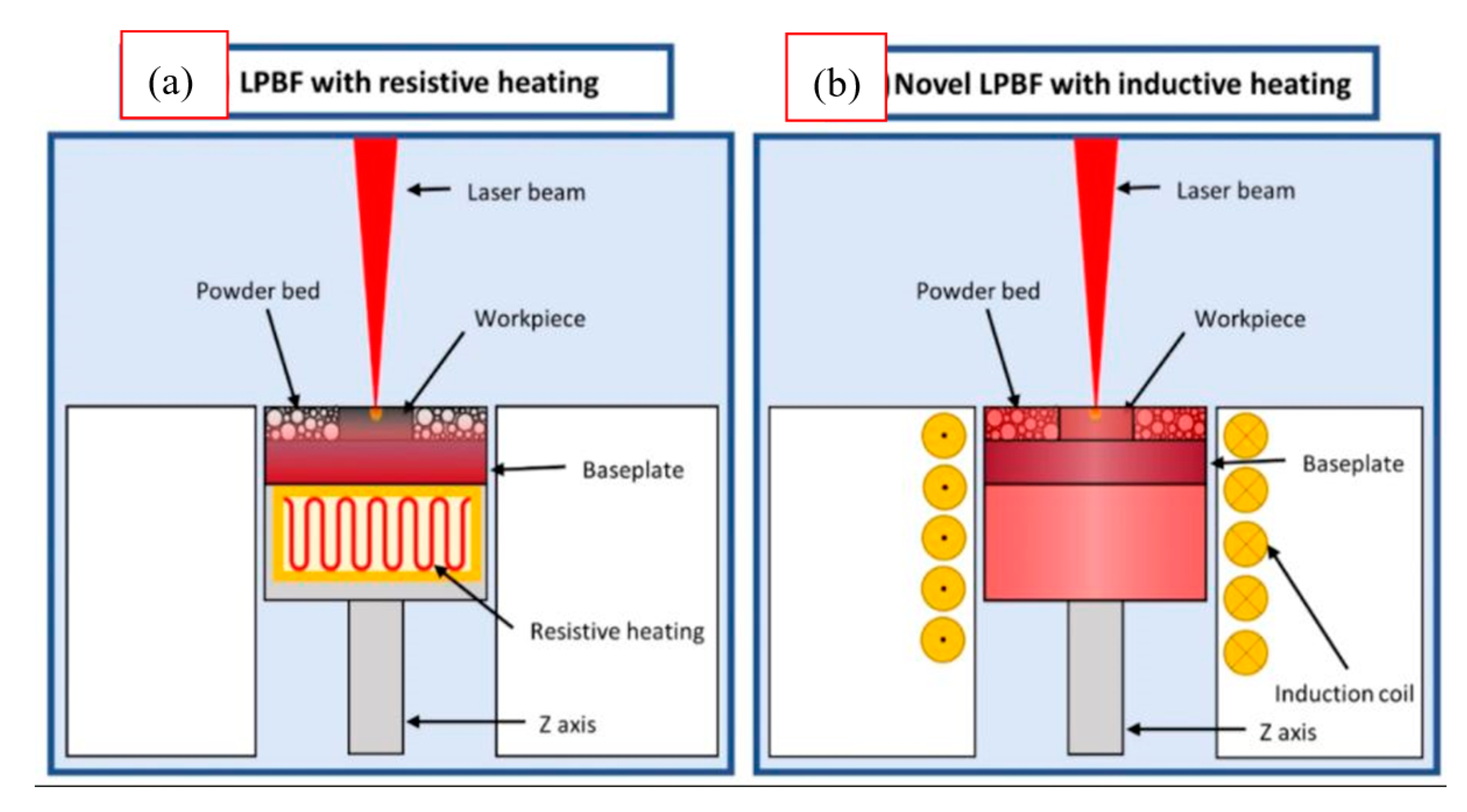
  90. Caprio, L.; Demir, A.G.; Chiari, G.; Previtali, B. Defect-free laser powder bed fusion of Ti–48Al–2Cr–2Nb with a high temperature inductive preheating system. J. Phys. Photonics 2020, 2, 024001. [Google Scholar] [CrossRef]
  91. Biamino, S.; Penna, A.; Ackelid, U.; Sabbadini, S.; Tassa, O.; Fino, P.; Pavese, M.; Gennaro, P.; Badini, C. Electron beam melting of Ti–48Al–2Cr–2Nb alloy: Microstructure and mechanical properties investigation. Intermetallics 2011, 19, 776–781. [Google Scholar] [CrossRef]
  92. Terner, M.; Biamino, S.; Epicoco, P.; Penna, A.; Hedin, O.; Sabbadini, S.; Fino, P.; Pavese, M.; Ackelid, U.; Gennaro, P. Electron beam melting of high niobium containing TiAl alloy: Feasibility investigation. Steel Res. Int. 2012, 83, 943–949. [Google Scholar] [CrossRef]
  93. Wu, X. Review of alloy and process development of TiAl alloys. Intermetallics 2006, 14, 1114–1122. [Google Scholar] [CrossRef]
  94. Dzogbewu, T.C. Additive manufacturing of TiAl-based alloys. Manuf. Rev. 2020, 7, 35. [Google Scholar] [CrossRef]
  95. Gussone, J.; Hagedorn, Y.-C.; Gherekhloo, H.; Kasperovich, G.; Merzouk, T.; Hausmann, J. Microstructure of γ-titanium aluminide processed by selective laser melting at elevated temperatures. Intermetallics 2015, 66, 133–140. [Google Scholar] [CrossRef]
  96. Löber, L.; Schimansky, F.P.; Kühn, U.; Pyczak, F.; Eckert, J. Selective laser melting of a beta-solidifying TNM-B1 titanium aluminide alloy. J. Mater. Process. Technol. 2014, 214, 1852–1860. [Google Scholar] [CrossRef] [Green Version]
  97. Doubenskaia, M.; Domashenkov, A.; Smurov, I.; Petrovskiy, P. Comprehensive analysis of selective laser melting of TiAl powder. In Proceedings of the Lasers Manufacture Conference, München, Germany, 26–29 June 2017. [Google Scholar]
  98. Mogale, N.F.; Matizamhuka, W.R. Spark plasma sintering of titanium aluminides: A progress review on processing, structure-property relations, alloy development and challenges. Metals 2020, 10, 1080. [Google Scholar] [CrossRef]
  99. Clemens, H.; Mayer, S. Design, processing, microstructure, properties, and applications of advanced intermetallic TiAl alloys. Adv. Eng. Mater. 2013, 15, 191–215. [Google Scholar] [CrossRef]
  100. Li, W.; Liu, J.; Wen, S.; Wei, Q.; Yan, C.; Shi, Y. Crystal orientation, crystallographic texture and phase evolution in the Ti–45Al–2Cr–5Nb alloy processed by selective laser melting. Mater. Charact. 2016, 113, 125–133. [Google Scholar] [CrossRef]
  101. Li, W.; Liu, J.; Zhou, Y.; Wen, S.; Wei, Q.; Yan, C.; Shi, Y. Effect of substrate preheating on the texture, phase and nanohardness of a Ti–45Al–2Cr–5Nb alloy processed by selective laser melting. Scr. Mater. 2016, 118, 13–18. [Google Scholar] [CrossRef]
  102. Okamoto, H.; Okamoto, H. Phase Diagrams for Binary Alloys; ASM International: Materials Park, OH, USA, 2000. [Google Scholar]
  103. Li, W.; Liu, J.; Zhou, Y.; Li, S.; Wen, S.; Wei, Q.; Yan, C.; Shi, Y. Effect of laser scanning speed on a Ti-45Al-2Cr-5Nb alloy processed by selective laser melting: Microstructure, phase and mechanical properties. J. Alloy. Compd. 2016, 688, 626–636. [Google Scholar] [CrossRef]
  104. Gussone, J.; Garces, G.; Haubrich, J.; Stark, A.; Hagedorn, Y.-C.; Schell, N.; Requena, G. Microstructure stability of γ-TiAl produced by selective laser melting. Scr. Mater. 2017, 105, 110–113. [Google Scholar] [CrossRef]
  105. Shi, X.; Ma, S.; Liu, C.; Wu, Q. Parameter optimization for Ti-47Al-2Cr-2Nb in selective laser melting based on geometric characteristics of single scan tracks. Opt. Laser Technol. 2017, 90, 71–79. [Google Scholar] [CrossRef]
  106. Shi, X.; Wang, H.; Feng, W.; Zhang, Y.; Ma, S.; Wei, J. The crack and pore formation mechanism of Ti–47Al–2Cr–2Nb alloy fabricated by selective laser melting. Int. J. Refract. Met. Hard Mater. 2020, 91, 105247. [Google Scholar] [CrossRef]
  107. Li, W.; Yang, Y.; Liu, J.; Zhou, Y.; Li, M.; Wen, S.; Wei, Q.; Yan, C.; Shi, Y. Enhanced nanohardness and new insights into texture evolution and phase transformation of TiAl/TiB2 in-situ metal matrix composites prepared via selective laser melting. Acta Mater. 2017, 136, 90–104. [Google Scholar] [CrossRef]
  108. Zhou, Y.; Lin, S.; Hou, Y.; Wang, D.; Zhou, P.; Han, P.; Li, Y.; Yan, M. Layered surface structure of gas-atomized high Nb-containing TiAl powder and its impact on laser energy absorption for selective laser melting. Appl. Surf. Sci. 2018, 441, 210–217. [Google Scholar] [CrossRef]
  109. Praveen, S.; Kim, H.S. High-entropy alloys: Potential candidates for high-temperature applications–An overview. Adv. Eng. Mater. 2018, 20, 1700645. [Google Scholar] [CrossRef]
  110. Chen, Y.; Li, Y.; Cheng, X.; Wu, C.; Cheng, B.; Xu, Z. The microstructure and mechanical properties of refractory high-entropy alloys with high plasticity. Materials 2018, 11, 208. [Google Scholar] [CrossRef] [PubMed] [Green Version]
  111. Ogura, M.; Fukushima, T.; Zeller, R.; Dederichs, P.H. Structure of the high-entropy alloy AlxCrFeCoNi: Fcc versus bcc. J. Alloy. Compd. 2017, 715, 454–459. [Google Scholar] [CrossRef]
  112. Cantor, B.; Chang, I.; Knight, P.; Vincent, A. Microstructural development in equiatomic multicomponent alloys. Mater. Sci. Eng. A 2004, 375, 213–218. [Google Scholar] [CrossRef]
  113. MacKay, R.A.; Gabb, T.P.; Smialek, J.L.; Nathal, M.V. A new approach of designing superalloys for low density. JOM 2010, 62, 48–54. [Google Scholar] [CrossRef] [Green Version]
  114. Yeh, A.; Tsao, T.; Chang, Y.; Chang, K.; Yeh, J.; Chiou, M.; Jian, S.; Kuo, C.; Wang, W.; Murakami, H. Developing new type of high temperature alloys–High entropy superalloys. Int. J. Metall. Mater. Eng. 2015, 1, 4. [Google Scholar]
  115. Yeh, A.-C.; Chang, Y.-J.; Tsai, C.-W.; Wang, Y.-C.; Yeh, J.-W.; Kuo, C.-M. On the solidification and phase stability of a Co-Cr-Fe-Ni-Ti high-entropy alloy. MMTA 2014, 45, 184–190. [Google Scholar] [CrossRef]
  116. Manzoni, A.M.; Singh, S.; Daoud, H.M.; Popp, R.; Völkl, R.; Glatzel, U.; Wanderka, N. On the path to optimizing the Al-Co-Cr-Cu-Fe-Ni-Ti high entropy alloy family for high temperature applications. Entropy 2016, 18, 104. [Google Scholar] [CrossRef] [Green Version]
  117. Tsao, T.K.; Yeh, A.C.; Kuo, C.M.; Murakami, H. On the superior high temperature hardness of precipitation strengthened high entropy Ni-based alloys. Adv. Eng. Mater. 2017, 19, 1600475. [Google Scholar] [CrossRef]
  118. Ranganathan, S. Alloyed pleasures: Multimetallic cocktails. Curr. Sci. 2003, 85, 1404–1406. [Google Scholar]
  119. Miracle, D.; Miller, J.; Senkov, O.; Woodward, C.; Uchic, M.; Tiley, J. Exploration and development of high entropy alloys for structural applications. Entropy 2014, 16, 494–525. [Google Scholar] [CrossRef]
  120. Murty, B.S.; Yeh, J.-W.; Ranganathan, S.; Bhattacharjee, P. High-Entropy Alloys; Elsevier: Amsterdam, The Netherlands, 2019. [Google Scholar]
  121. Guo, J.; Goh, M.; Zhu, Z.; Lee, X.; Nai, M.L.S.; Wei, J. On the machining of selective laser melting CoCrFeMnNi high-entropy alloy. Mater. Des. 2018, 153, 211–220. [Google Scholar] [CrossRef]
  122. Brif, Y.; Thomas, M.; Todd, I. The use of high-entropy alloys in additive manufacturing. Scr. Mater. 2015, 99, 93–96. [Google Scholar] [CrossRef]
  123. Piglione, A.; Dovgyy, B.; Liu, C.; Gourlay, C.M.; Hooper, P.A.; Pham, M.S. Printability and microstructure of the CoCrFeMnNi high-entropy alloy fabricated by laser powder bed fusion. Mater. Lett. 2018, 224, 22–25. [Google Scholar] [CrossRef]
  124. Zhang, C.; Feng, K.; Kokawa, H.; Han, B.; Li, Z. Cracking mechanism and mechanical properties of selective laser melted CoCrFeMnNi high entropy alloy using different scanning strategies. Mater. Sci. Eng. A 2020, 789, 139672. [Google Scholar] [CrossRef]
  125. Zhu, Z.; An, X.; Lu, W.; Li, Z.; Ng, F.; Liao, X.; Ramamurty, U.; Nai, S.; Wei, J. Selective laser melting enabling the hierarchically heterogeneous microstructure and excellent mechanical properties in an interstitial solute strengthened high entropy alloy. Mater. Res. Lett. 2019, 7, 453–459. [Google Scholar] [CrossRef] [Green Version]
  126. Chen, P.; Li, S.; Zhou, Y.; Yan, M.; Attallah, M.M. Fabricating CoCrFeMnNi high entropy alloy via selective laser melting in-situ alloying. J. Mater. Sci. Technol. 2020, 43, 40–43. [Google Scholar] [CrossRef]
  127. Chen, P.; Yang, C.; Li, S.; Attallah, M.M.; Yan, M. In-situ alloyed, oxide-dispersion-strengthened CoCrFeMnNi high entropy alloy fabricated via laser powder bed fusion. Mater. Des. 2020, 194, 108966. [Google Scholar] [CrossRef]
  128. Li, R.; Niu, P.; Yuan, T.; Cao, P.; Chen, C.; Zhou, K. Selective laser melting of an equiatomic CoCrFeMnNi high-entropy alloy: Processability, non-equilibrium microstructure and mechanical property. J. Alloy. Compd. 2018, 746, 125–134. [Google Scholar] [CrossRef]
  129. Lin, D.; Xu, L.; Jing, H.; Han, Y.; Zhao, L.; Minami, F. Effects of annealing on the structure and mechanical properties of FeCoCrNi high-entropy alloy fabricated via selective laser melting. Addit. Manuf. 2020, 32, 101058. [Google Scholar] [CrossRef]
  130. Sun, Z.; Tan, X.P.; Descoins, M.; Mangelinck, D.; Tor, S.B.; Lim, C.S. Revealing hot tearing mechanism for an additively manufactured high-entropy alloy via selective laser melting. Scr. Mater. 2019, 168, 129–133. [Google Scholar] [CrossRef]
  131. Fujieda, T.; Chen, M.; Shiratori, H.; Kuwabara, K.; Yamanaka, K.; Koizumi, Y.; Chiba, A.; Watanabe, S. Mechanical and corrosion properties of CoCrFeNiTi-based high-entropy alloy additive manufactured using selective laser melting. Addit. Manuf. 2019, 25, 412–420. [Google Scholar] [CrossRef]
  132. Park, J.M.; Choe, J.; Park, H.K.; Son, S.; Jung, J.; Kim, T.-S.; Yu, J.-H.; Kim, J.G.; Kim, H.S. Synergetic strengthening of additively manufactured (CoCrFeMnNi)99C1 high-entropy alloy by heterogeneous anisotropic microstructure. Addit. Manuf. 2020, 35, 101333. [Google Scholar]
  133. Park, J.M.; Choe, J.; Kim, J.G.; Bae, J.W.; Moon, J.; Yang, S.; Kim, K.T.; Yu, J.-H.; Kim, H.S. Superior tensile properties of 1% C-CoCrFeMnNi high-entropy alloy additively manufactured by selective laser melting. Mater. Res. Lett. 2020, 8, 1–7. [Google Scholar] [CrossRef] [Green Version]
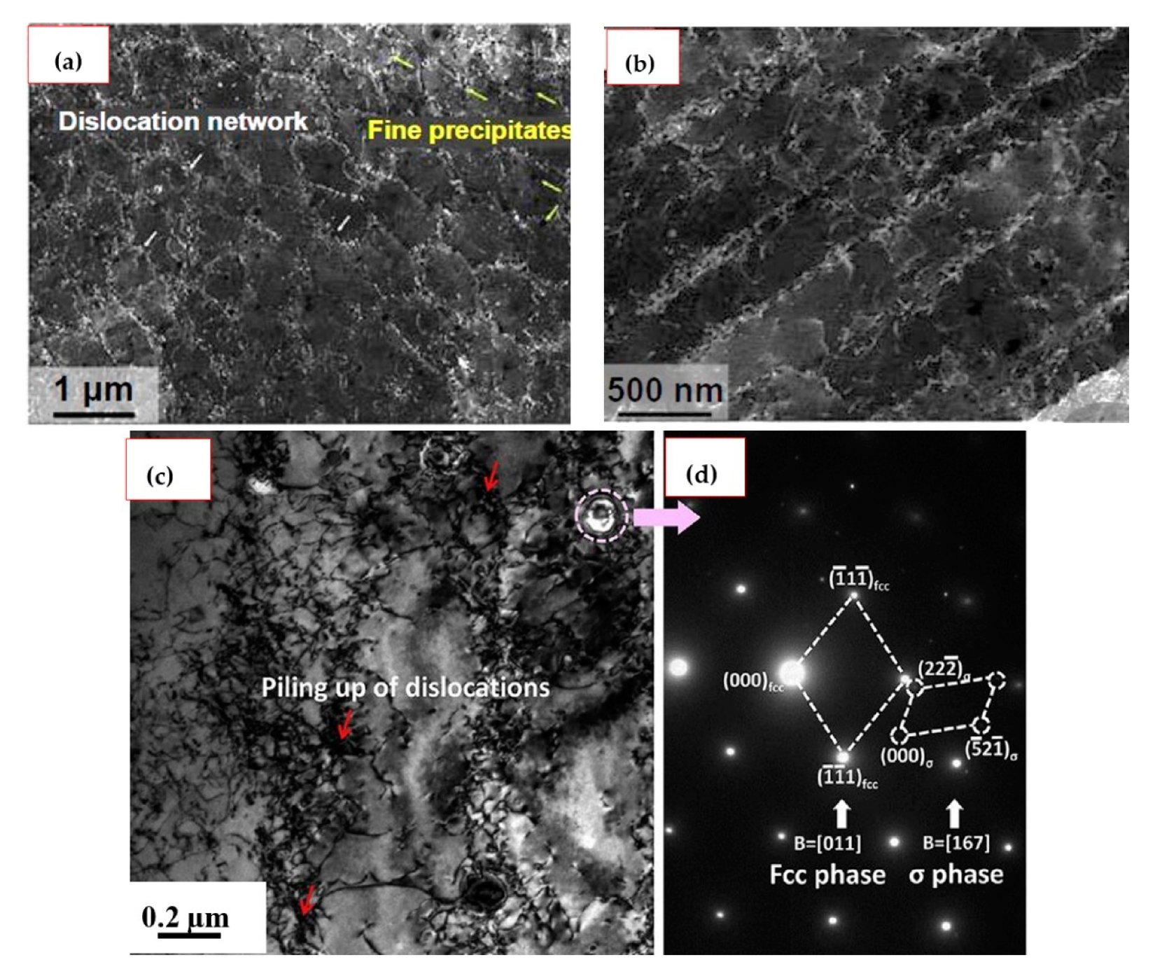
  134. Wu, W.; Zhou, R.; Wei, B.; Ni, S.; Liu, Y.; Song, M. Nanosized precipitates and dislocation networks reinforced C-containing CoCrFeNi high-entropy alloy fabricated by selective laser melting. Mater. Charact. 2018, 144, 605–610. [Google Scholar] [CrossRef]
  135. Zhou, R.; Liu, Y.; Zhou, C.; Li, S.; Wu, W.; Song, M.; Liu, B.; Liang, X.; Liaw, P. Microstructures and mechanical properties of C-containing FeCoCrNi high-entropy alloy fabricated by selective laser melting. Intermetallics 2018, 94, 165–171. [Google Scholar] [CrossRef]
  136. Lin, D.; Xu, L.; Li, X.; Jing, H.; Qin, G.; Pang, H.; Minami, F. A Si-containing FeCoCrNi high-entropy alloy with high strength and ductility synthesized in situ via selective laser melting. Addit. Manuf. 2020, 35, 101340. [Google Scholar] [CrossRef]
  137. Luo, S.; Zhao, C.; Su, Y.; Liu, Q.; Wang, Z. Selective laser melting of dual phase AlCrCuFeNix high entropy alloys: Formability, heterogeneous microstructures and deformation mechanisms. Addit. Manuf. 2020, 31, 100925. [Google Scholar] [CrossRef]
  138. Yao, H.; Tan, Z.; He, D.; Zhou, Z.; Zhou, Z.; Xue, Y.; Cui, L.; Chen, L.; Wang, G.; Yang, Y. High strength and ductility AlCrFeNiV high entropy alloy with hierarchically heterogeneous microstructure prepared by selective laser melting. J. Alloy. Compd. 2020, 813, 152196. [Google Scholar] [CrossRef]
  139. Peyrouzet, F.; Hachet, D.; Soulas, R.; Navone, C.; Godet, S.; Gorsse, S. Selective laser melting of Al0.3CoCrFeNi high-entropy alloy: Printability, microstructure, and mechanical properties. JOM 2019, 71, 3443–3451. [Google Scholar] [CrossRef] [Green Version]
  140. Zhou, P.; Xiao, D.; Wu, Z.; Ou, X. Al0.5FeCoCrNi high entropy alloy prepared by selective laser melting with gas-atomized pre-alloy powders. Mater. Sci. Eng. A 2019, 739, 86–89. [Google Scholar] [CrossRef]
  141. Karlsson, D.; Marshal, A.; Johansson, F.; Schuisky, M.; Sahlberg, M.; Schneider, J.M.; Jansson, U. Elemental segregation in an AlCoCrFeNi high-entropy alloy–A comparison between selective laser melting and induction melting. J. Alloy. Compd. 2019, 784, 195–203. [Google Scholar] [CrossRef]
  142. Niu, P.; Li, R.; Yuan, T.; Zhu, S.; Chen, C.; Wang, M.; Huang, L. Microstructures and properties of an equimolar AlCoCrFeNi high entropy alloy printed by selective laser melting. Intermetallics 2019, 104, 24–32. [Google Scholar] [CrossRef]
  143. Sathiyamoorthi, P.; Kim, H.S. High-entropy alloys with heterogeneous microstructure: Processing and mechanical properties. Prog. Mater. Sci. 2020, 100709, in press. [Google Scholar] [CrossRef]
  144. Zhu, Z.G.; Nguyen, Q.B.; Ng, F.L.; An, X.H.; Liao, X.Z.; Liaw, P.K.; Nai, S.M.L.; Wei, J. Hierarchical microstructure and strengthening mechanisms of a CoCrFeNiMn high entropy alloy additively manufactured by selective laser melting. Scr. Mater. 2018, 154, 20–24. [Google Scholar] [CrossRef]
  145. Beyramali Kivy, M.; Asle Zaeem, M. Generalized stacking fault energies, ductilities, and twinnabilities of CoCrFeNi-based face-centered cubic high entropy alloys. Scr. Mater. 2017, 139, 83–86. [Google Scholar] [CrossRef]
  146. Zhang, S.; Zhang, C.; Du, Z.; Hou, Z.; Lin, P.; Chen, Y. Microstructure and tensile properties of hot fogred high Nb containing TiAl based alloy with initial near lamellar microstructure. Mater. Sci. Eng. A 2015, 642, 16–21. [Google Scholar] [CrossRef]
  147. Jabbar, H.; Monchoux, J.-P.; Houdellier, F.; Dollé, M.; Schimansky, F.-P.; Pyczak, F.; Thomas, M.; Couret, A. Microstructure and mechanical properties of high niobium containing TiAl alloys elaborated by spark plasma sintering. Intermetallics 2010, 18, 2312–2321. [Google Scholar] [CrossRef] [Green Version]
  148. Liu, L.; Ding, Q.; Zhong, Y.; Zou, J.; Wu, J.; Chiu, Y.-L.; Li, J.; Zhang, Z.; Yu, Q.; Shen, Z. Dislocation network in additive manufactured steel breaks strength–ductility trade-off. Mater. Today 2018, 21, 354–361. [Google Scholar] [CrossRef] [Green Version]
  149. Kim, J.; Wakai, A.; Moridi, A. Materials and manufacturing renaissance: Additive manufacturing of high-entropy alloys. J. Mater. Res. 2020, 35, 1963–1983. [Google Scholar] [CrossRef]
  150. Löber, L.; Biamino, S.; Ackelid, U.; Sabbadini, S.; Epicoco, P.; Fino, P.; Eckert, J. Comparison of selective laser and electron beam melted titanium aluminides. In Proceedings of the Conference Paper of 22nd International Symposium “Solid Freeform Fabrication Proceedings”, Austin, TX, USA, 8–10 August 2011; pp. 547–556. [Google Scholar]
  151. Yang, Y.; Wen, S.; Wei, Q.; Li, W.; Liu, J.; Shi, Y. Effect of scan line spacing on texture, phase and nanohardness of TiAl/TiB2 metal matrix composites fabricated by selective laser melting. J. Alloy. Compd. 2017, 728, 803–814. [Google Scholar] [CrossRef]
  152. Kenel, C.; Leinenbach, C. Influence of Nb and Mo on microstructure formation of rapidly solidified ternary Ti–Al- (Nb, Mo) alloys. Intermetallics 2016, 69, 82–89. [Google Scholar] [CrossRef]
  153. Kenel, C.; Leinenbach, C. Influence of cooling rate on microstructure formation during rapid solidification of binary TiAl alloys. J. Alloy. Compd. 2015, 637, 242–247. [Google Scholar] [CrossRef]
Figure 1. The laser powder bed fusion (LPBF) process. The build direction is defined by the z-axis [34].
Metals 11 00058 g001
Figure 2. LPBF process parameters: laser power, scanning speed, hatch spacing, and layer thickness [43].
Metals 11 00058 g002
Figure 3. Four different scanning strategies adopted in the direct laser sintering of tool steels using an Nd:YAG laser machine. The numbers indicate the scanning sequence, while the arrows represent the scanning directions [61].
Metals 11 00058 g003
Figure 4. LPBF scanning strategies: (a) standard, (b) diagonal and (c) perimeter [62].
Metals 11 00058 g004
Figure 5. Schematic representation of the “island” scan strategy. The black arrows represent the scan vectors within each of the “islands” with the distance between these vectors defined as the scan spacing [65].
Metals 11 00058 g005
Figure 6. Schematics of (a) conventional scanning strategy; and the three types of overlapping regimes namely (b) intra-, (c) inter- (d) mixed layer overlapping under the inter-layer stagger scanning strategy [70].
Metals 11 00058 g006
Figure 7. Schematic illustration of the (a) 67°, (b) 90°, (c) 180° scanning strategy. (BD, SD, and TD indicate building direction, scanning direction and transverse direction, respectively). Figures were adapted from [73,74,75] respectively.
Metals 11 00058 g007
Figure 8. Midsection of the binary Ti-Al phase diagram and representative microstructures obtained through heat treatments within the α - and ( α + γ ) -phase field. Note that the left half of the microstructural image represents a light-optical microscope (OM) image, whereas the right half is an SEM image taken in BSE mode, i.e., γ -TiAl appears dark, whereas α 2 -Ti3Al shows a light contrast. Heat treatments: little above the eutectoid temperature ( T e u ) → near gamma (NG) microstructure; between T e u and α -transus temperature T α → duplex (DM) microstructure. The volume fraction of lamellar grains depends on the heat treatment temperature relative to ( T e u ) and T α ; just below T α → nearly lamellar (NL) microstructure. The designation NL γ stands for a NL microstructure exhibiting a defined volume fraction of globular γ-grains, above T α → FL microstructure [99].
Metals 11 00058 g008
Figure 9. Binary phase diagram of TiAl alloys [102].
Metals 11 00058 g009
Figure 10. SEM micrographs of LPBF as-built condition showing (a) a very fine irregular near-lamellar structure ( γ and β / β 0 decorating α 2 / γ colony boundaries) [104], (b,c) near-lamellar β microstructure of a TNM-B1 alloy [96], (d) a fine lath-shaped α 2 -Ti3Al phase in a Ti-48Al-2Mn-5Nb (at.%) alloy [87], (e) microstructure (high magnification) of Ti–45Al–2Cr–5Nb observed from the top view. The characterisation of Ti-45Al-2Cr-5Nb alloy was distinguished into (e) three regions. The local amplification of A, B, C regions were indicated in (fh), respectively [100].
Metals 11 00058 g010
Figure 11. SEM image of microstructure of an LPBF-processed (a) CoCrFeNi HEA [129], (b) Fe49.5Mn30Co10Cr10C0.5 (at.%) HEA (with inset showing the equiaxed cellular structures) [125]; (c) cellular structure in CoCrFeMnNi in greater detail [123], (d,e) bright-field TEM images of the cellular and columnar structures respectively in C-containing CoCrFeNi HEA [134].
Metals 11 00058 g011
Figure 12. Schematic diagram of substructure formation: (a) Initial and (b) final stages of the solidification process [129].
Metals 11 00058 g012
Figure 13. ECC images showing the dislocation networks and fine oxides in LPBF-processed equiatomic CoCrFeMnNi HEA: (a) cellular structure and (b) columnar structure [75]; (c) TEM bright-field showing the high density of dislocation piled up and dislocation network and (d) SAED pattern showing the primary FCC phase and tetragonal σ precipitate phase [128].
Metals 11 00058 g013
Figure 14. (a) LPBF with standard resistive preheating system and (b) novel LPBF with the inductive heating system [90].
Metals 11 00058 g014
Table 1. LPBF process parameters and material properties influencing the processing and densification [41].
LPBF Processing ParametersMaterials Characteristics
Type of commercial equipmentParticle morphology
Laser typeParticle size and distribution
Laser powerChemical composition
Scan speedAbsorptivity (or reflectivity)
Scan radiusMelting temperature
Scan Hatch spacingSpecific heat
Scan vector lengthThermal conductivity
Layer thicknessViscosity
Processing environmentSurface tension
Gas flowEmissivity
Heaters (bed temperature)Component ratio
Scan strategyBoiling point
Table 2. Absorptivity of metallic powders to CO2 and Nd:YAG laser radiation [37,41].
MaterialCO2 Laser
(λ = 10.6 µm)
Nd:YAG Laser
(λ = 1.06 µm)
Cu0.260.59
Fe0.450.64
Sn0.230.66
Ti0.590.77
Pb-0.79
Cu-10Al (wt.%)0.320.63
Co-alloy (1% C; 28% Cr; 4% W)0.250.58
Ni-alloy I (13% Cr; 3% B; 4% Si; 0.6% C)0.640.42
Ni-alloy II (15% Cr; 3.1% Si; 4%; 0.8% C)0.720.51
Fe-3C-3Cr-12 V + 10TiC (wt.%)0.390.65
Fe-0.6C-4Cr-2Mo-1Si + 15TiC (wt.%)0.420.71
Fe-1C-14Cr-10Mn-6Ti + 66TiC (wt.%)0.440.79
Table 3. Composition, phases, processing parameters, relative density, and microstructure for LPBFed TiAl-based alloys.
TiAl-Based Alloy Composition (at.%)Phase CompositionLPBF Process ParametersReported Relative DensityMicrostructureReference
Laser Power (W)Scanning Speed (mm·s−1)Hatch Scan Distance (µm)Layer Thickness (µm)Scan Strategy
Ti-48Al-2Cr-2Nb α 2 + γ 90600906090°93% ± 2%Lamellar [33]
09077% ± 2%
10008084% ± 3%
14008078% ± 4%
Ti-47Al-2Cr-2Nb α 2 + γ 20020-100-98.95%- [105]
0.3cross scanning94.1%Near-lamellar [106]
300.2594.3%
250300.392.5%
400.2593.4%
300400.389.3%
500.2591.0%
Ti-47Al-2Cr-2Nb γ (as built); α 2 + γ (after heat treatment)5050160---mixed (as built); duplex or fully lamellar (after heat treatments) [86]
Ti-44.8Al-6Nb-1.0Mo-0.1B α 2 + γ + β / β 0 8045010030cross-hatching scan strategy with zigzag scan
vectors
mixed [95,104]
Ti-45Al-2Cr-5Nb α 2 + γ + B 2 25050010020long bidirectional scanning
vectors with 90° rotation between consecutive layers
97.18%mixed [100]
300-
350-
20040010030- [101]
50092.25%equiaxed [103]
60091.79%
70091.33%
80090.68%
Ti-45Al-2Cr-5Nb + (0 wt.% TiB2) α 2 + γ + B 2 + T i B 2 3008001003093.44% [107]
Ti-45Al-2Cr-5Nb + (1 wt.% TiB2)92.18%
Ti-45Al-2Cr-5Nb + (2 wt.% TiB2)91.33%
Ti-45Al-2Cr-5Nb + (3 wt.% TiB2)85.16%
Ti-28.9Al-9.68Nb-2.26Mo-0.024B wt.% α 2 + β 1005030075stripe hatching99.0%fine grained nearly lamellar [96]
1751000
Ti-45Al-8Nb-18055012030-98.70%- [108]
Table 4. Composition, lattice structure, processing parameters, relative density, and microstructure for LPBFed HEAs.
HEA CompositionLattice StructureLPBF Process ParametersReported Relative Density (or Max Density Achieved)MicrostructureReference
Laser Power (W)Scanning Speed (mm·s−1)Hatch Scan Distance (µm)Layer Thickness (µm)Scan Strategy
CoCrFeNiMnFCC24020005040-99.2%- [121]
FCC200-12560unidirectional99.29%columnar [123]
FCC2402000504090°99.2%mixed [125]
FCC2402500504090°97.1%mixed
FCC2808006030Chessboard pattern7.89 g·cm−3columnar [126,127]
FCC160120050300°, 67°, 90°-columnar [124]
FCC + tetragonal σ4002000903067°98.2%mixed [128]
CoCrFeNiFCC200740404067°99.71% ± 0.25%mixed [129]
FCC200300-20--- [122]
FCC15027010050chessboard and stripe/bi-directional98.7%columnar [130]
Co1.5CrFeNi1.5Ti0.5Mo0.1SC + FCC16065010040-99.3%columnar [131]
(CoCrFeMnNi)99C1FCC + Mn-rich oxide and sulfide, Cr-rich carbide906008025180° with raster scanning pattern-mixed [132]
902008025-columnar [133]
CoCrFeNiC0.05FCC4008001105067°99%- [134,135]
CoCrFeNiSi1.5FCC197-414067°99.01 ± 0.11mixed [136]
133-974099.85 ± 0.13
AlCoCrCuFeNiFCC + BCC3001600904067°7.08 g·cm−3mixed [73]
AlCrCuFeNix (x = 2.0, 2.5, 2.75,3.0)FCC + BCC (B2) (of nanoscale lamellar or cellular structures)200400802090°>99.7%mixed [137]
AlCrCuFeNiBCC (containing B2 + Cu-rich nano precipitates)300600804090°>99.7%columnar [74]
Al0.5Cr0.9FeNi2.5V0.2FCC + L12140900503067°99.88%mixed [138]
Al0.3CrFeCoNiFCC1601100452567°99.9%columnar [139]
Al0.5CrFeCoNiFCC4001600904067°-mixed [140]
AlCoCrFeNiBCC + B2982000522067°-equiaxed [141]
AlCoCrFeNiBCC + B24001000904067°98.4%mixed [142]
Fe49.5Mn30Co10Cr10C0.5FCC1801000554067°-mixed [125]
Table 5. Composition, mechanical properties, and findings of LPBFed TiAl alloys.
TiAl-Based Alloy Composition
(at.%)
Mechanical Property
Evaluated
Main FindingsReference
Ti- 48Al-2Cr-2NbCompression
  • Young modulus was 50 ± 13 GPa
  • Ultimate compression stress of 612 ± 56 MPa
  • Poor mechanical properties were attributed to the presence of high porosity in alloy
[150]
Ti-44.8Al-6Nb-1.0Mo-0.1BTensile at room and high temperature (850 °C)
  • Tensile strength ca. 200–400 MPa at room temperature
  • High-temperature tensile strength ca. 541–545 MPa
  • Tensile strength at both room and high temperature was in the range of conventional γ-TiAl alloys
[95]
(47- x)Ti- 48Al-2Mn-xNb
(x = 3, 4, 5, 6, 7)
Microhardness, compression, and friction-wear
  • Hardness and coefficient of friction fluctuated with increasing Nb contents
  • Ultimate compression strength and fracture strain ranged from 1295 MPa (22.5%) to 1390 MPa (24.5%)
  • Alloy with 7.0 at.% Nb showed the best combination of mechanical and tribological properties
[87]
Ti-45Al-2Cr-5NbNanohardness
  • Superior nanohardness ranging from 7.57 ± 0.38 GPa–8.74 ± 0.42 GPa compared to 4.8 ± 0.28 GPa of conventional casting processed TiAl alloys
[101]
Ti-45Al-2Cr-5Nb + (xTiB2)
(x = 1, 2, 3 wt.%)
Nanohardness
  • Enhanced hardness ranging from 9.38 ± 0.47 GPa–10.57 ± 0.53 GPa which is higher than that of traditional roll bonding fabricated TiAl alloys reinforced with TiB2
[106]
Ti- 48Al-2Cr-2NbMicrohardness
  • Microhardness ranged between 548 ± 13–559 ± 18 HV0.3
  • Increase in microhardness was attributed to cooling rates and residual stresses
[33]
Ti-28.9Al-9.68Nb-2.26Mo-0.024B wt.%Compression
  • Slightly lower compression performance compared to the cast samples.
  • This was attributed to residual porosity in the samples
[96]
Ti-45Al-2Cr-5Nb + (1 wt.% TiB2)Nanohardness
  • Superior nanohardness compared than conventional roll bonding TiAl/TiB2 metal-matrix composites
[151]
Table 6. Composition, mechanical properties, and findings of LPBFed HEAs.
HEA CompositionReported Relative Density (or Max Density Achieved)Mechanical Properties EvaluatedMain FindingsReference
CoCrFeNiMn99.2%Microhardness
  • Microhardness of 300 HV
  • The high microhardness was attributed to compressive stresses of the LPBF process and from the milling and grinding processes.
[121]
99.2%Tensile
  • Yield strength of 510 ± 10 MPa
  • Ultimate tensile strength of 609 ± 10 MPa
  • Elongation of 34 ± 3%
  • Enhanced strength was to dislocation strengthening in addition to friction stress and grain boundary strengthening in the alloy.
  • Excellent uniform elongation was due to strain hardening capabilities at high stress levels
[144]
-Compression
  • Yield strength of 778.4 MPa (in the scanning direction), 766.4 MPa (transverse direction) and 703.5 MPa (building direction)
  • Orowan strengthening mechanism was the highest contributor in the superior strength of the alloy
[75]
7.89 g.cm−3Microhardness, tensile
  • Microhardness of 261 ± 7 HV
  • Yield strength of 624 ± 4 MPa
  • Ultimate tensile strength of 747 ± 2 MPa
  • Elongation of 12.3 ± 0.2%
  • Orowan strengthening indicates oxides formed play a key role in mechanical properties of the alloy.
  • The tensile ductility of the alloy was lower than the ones prepared by using fully pre-alloyed powders.
[126,127]
98.2%Tensile
  • The formations σ phase and ultrafine grains account for the enhancement of mechanical property of alloy compared with slowly solidified HEA.
  • After HIP, the densification and tensile strength improved from 601 MPa to 649 MPa while the elongation decreased from 35.0% to 18%.
[128]
CoCrFeNi99.71% ± 0.25%Microhardness, tensile and impact toughness
  • Microhardness decreased from 219 HV (no heat treatment) to 138 HV (annealed at 1300 °C)
  • The yield strength decreased gradually, the plasticity increased gradually, and the tensile strength hardly changed with increasing annealing temperature.
  • Impact toughness increased with increasing annealing temperature.
  • Formation of dislocation networks and recrystallisation characterise mechanical properties of the alloy due to annealing.
[129]
98.7%Tensile
  • Yield strength of 556.7 ± 23.6 (chessboard scan) and 572 ± 7.5 MPa (Stripe scan)
  • Ultimate tensile strength of 676.7 ± 20.5 (chessboard scan) and 691.0 ± 15.9 MPa (stripe scan)
  • Elongation of 12.4 ± 2.1% (chessboard scan) and 17.9 ± 0.9% (stripe scan)
  • Hot cracks in built alloy accounted for fracture of alloy.
[130]
Co1.5CrFeNi1.5Ti0.5Mo0.199.3%TensileAs-built
  • Yield strength of 773.0 ± 4.2 MPa
  • Ultimate tensile strength of 1178.0 MPa
  • Elongation of 25.8 ± 0.6%
Solution treated at 1120 °C and water quenched
  • Yield strength of 897.5 ± 65.8 MPa
  • Ultimate tensile strength of 1291.0 ± 29.7 MPa
  • Elongation of 26.7 ± 2.3%
Solution treated at 1120 °C and air-cooled
  • Yield strength of 935.5 ± 9.2 MPa
  • Ultimate tensile strength of 1414.5 ± 0.7 MPa
  • Elongation of 13.7 ± 0.4%
[131]
(CoCrFeMnNi)99C1-Tensile
  • Yield strength of 741 MPa (in the X-direction)
  • Ultimate tensile strength of ~874 MPa (in the X-direction)
  • Differences in tensile properties were attributed to the heterogeneous anisotropic microstructure of the alloy with respect to loading axes and variations in the dislocation mean free path.
[132]
  • Enhancement of yield strength compared with the as-cast
  • The primary strengthening mechanism in the alloy were combinations of dislocation hardening, grain refinement, and precipitation hardening.
[133]
CoCrFeNiC0.0599%Tensile
  • Yield strength of ~638 MPa
  • Ultimate tensile strength of ~795 MPa
  • Elongation of ~13.5%
  • The yield strength of alloy was higher compared to those processed using conventional methods such as casting and rolling
  • Outstanding yield strength of the alloy was attributed to dislocation networks strengthening and nanosized carbides strengthening.
[134,135]
AlCoCrCuFeNi7.08 g.cm−3Microhardness
  • Outstanding microhardness of 710.4 HV compared to the corresponding material manufactured by traditional methods.
[73]
AlCrCuFeNix (x=2.0, 2.5. 2.75,3.0)> 99.7%Tensile
  • AlCrCuFeNi3 HEA showed superior mechanical properties compared to as-cast and cold-rolled plus annealed AlCrCuFeNi HEA systems.
  • AlCrCuFeNi3 HEA was crack-free and exhibited remarkably heterogeneous microstructures including near-equiaxed grains, nanoscale lamellar or cellular dual-phase (FCC+ B2) structures, massive LAGBs and dislocation pile-ups, as well as profuse coherent A2 nano-precipitates embedded in the B2 phase.
[137]
AlCrCuFeNi> 99.7%Compression
  • Ultimate tensile strength of 2052.8 ± 123.6 MPa
  • Elongation of 6.8 ± 1.3%
  • The compressive properties of the alloy were superior to those of cast due to ultrafine grains and nano-scale alternating bright and dark structures.
[74]
Al0.5Cr0.9FeNi2.5V0.299.88%Tensile
  • The yield stress and the ultimate tensile strength of alloy (651.36 MPa, 1057.21 MPa) were superior to those of casted samples (489.63 MPa, 873.09 MPa).
  • Hierarchical structure from nano-scale (L12 nanophase, pre-existence dislocations) to sub-micron scale (sub-grain boundaries and grain boundaries) progressively hindered dislocation motion. In addition, heterogeneous distribution of the dislocation density and subgrains morphology influenced deformation, hence achieving the balance of high strength and ductility.
[138]
Al0.3CrFeCoNi99.9%Tensile
  • Superior tensile strength (yield strength of 730 MPa, an ultimate tensile strength of 896 MPa and elongation of 29%) compared to as-cast or wrought counterparts.
  • Improved tensile properties were attributed to the presence of numerous dislocation densities combined with the effect anisotropy due to the crystallographic texture.
[139]
Al0.5CrFeCoNi-Microhardness, tensile
  • Microhardness of 262 ± 5 HV
  • Improved tensile properties (yield strength of 579 MPa, ultimate tensile strength of 721 MPa and elongation of 22%) compared to cast sample.
[140]
AlCoCrFeNi98.4%Microhardness
  • Higher microhardness (632.8 HV) than samples fabricated by other methods such as casting, laser engineered net shaping (LENS), and EBM
  • Higher microhardness was attributed to the high VED in the much more rapid cooling rate and the formation of more B2 phases.
[142]
Fe49.5Mn30Co10Cr10C0.5-Tensile
  • Enhanced strength-ductility combination relative to those fabricated by conventional processing routes.
  • The high yield strength mainly stemmed from the dislocation strengthening, friction stress and grain boundary strengthening.
[125]
Publisher’s Note: MDPI stays neutral with regard to jurisdictional claims in published maps and institutional affiliations.

