Abstract
The aim of this study was to investigate cracking behavior of AISI 304 stainless steel that had been exposed to a high temperature MgCl2 solution for several years. The microstructure of the cracked area of the reactor was studied by in-depth microstructural characterization. Transgranular stress corrosion cracking only occurred at the cold-formed part of the reactor. It was observed that approximately 10–20% of the austenite matrix was transformed into alpha prime martensite due to cold forming at the lower head of the reactor. The preferential path for crack propagation was found to be strain-induced alpha prime martensite. The present study reveals that strain-induced martensitic transformation in austenitic stainless steel has a negative effect on stress corrosion cracking.
1. Introduction
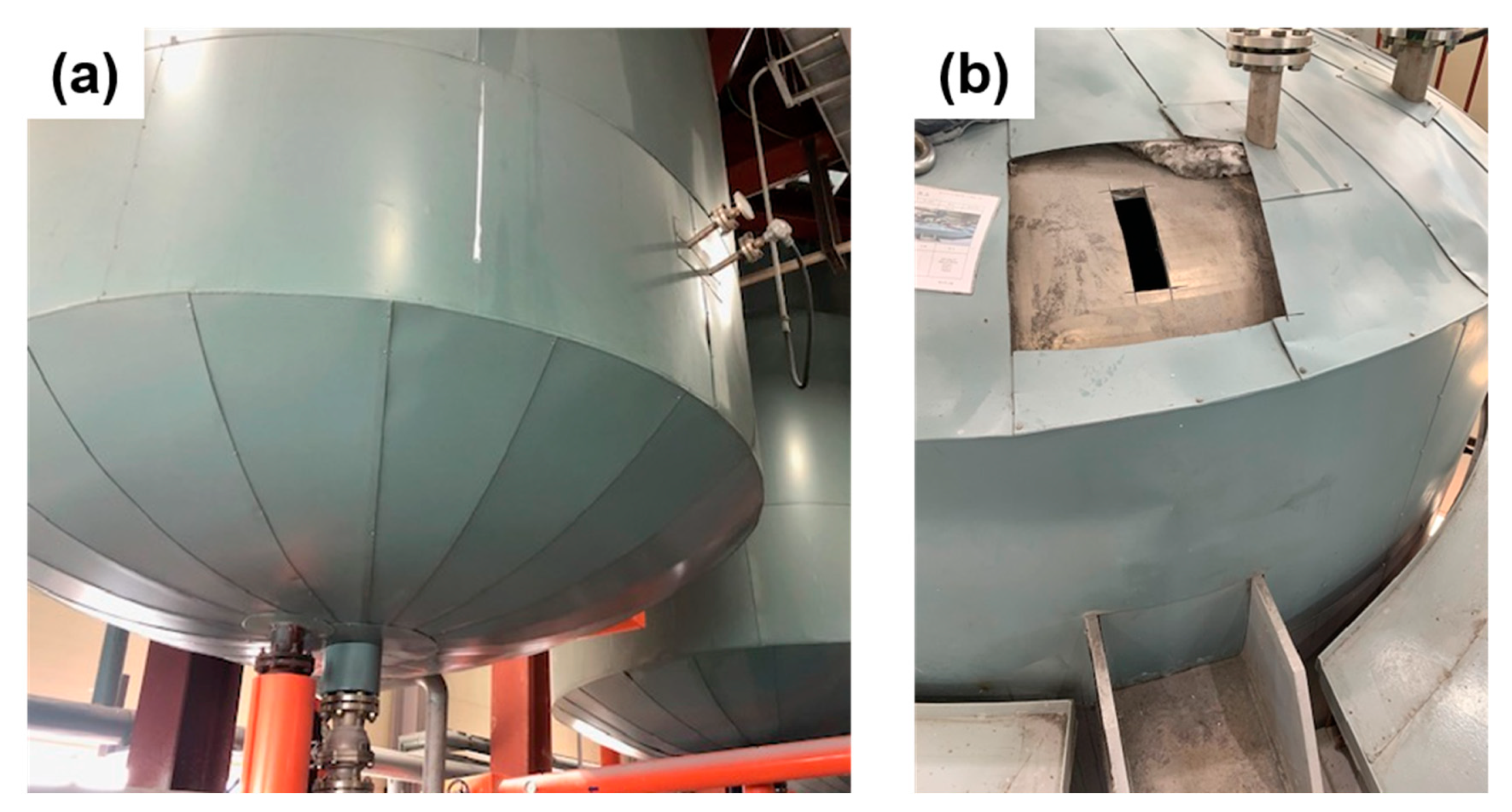
Austenitic stainless steels have been widely used as a reactor material for chemical plants due to their great corrosion resistance and workability along with good weldability. Since the 3XX series of austenitic stainless steels contain a minimum of 11 wt% of Cr content, they have a thin passive oxide film of chromia (Cr2O3) and it allows the alloys to be highly resistant to general corrosion in an aqueous solution. However, austenitic stainless steels such as AISI 304 and 316 are known to suffer from SCC (stress corrosion cracking) [1,2,3,4,5,6,7,8]. SCC is considered to be one of the main damage mechanisms to cause failures of the components in petrochemical industries. These failures have the potential to release hazardous substances or lead to a catastrophic event such as massive fires [9,10,11,12,13]. Research involved in stress corrosion cracking has been reported for decades, still the exact mechanism of stress corrosion cracking is not fully understood since its occurrence and the type of cracks widely vary under various environments. SCC could occur in susceptible alloys under simultaneous exposure to a corrosive environment and sustained stress and the combination of those three factors produce diverse cases of SCC. Accordingly, constant efforts to analyze cases of SCC in the industry field should be made and based on that, we would be able to approach a deep understanding of the SCC mechanism. Sometimes, a practical case provides us with valuable insights for understanding the phenomenon rather than a well-designed laboratory experiment. The present study introduces a case of damage on a AISI 304 reactor for producing a PVC (polyvinyl chloride) stabilizer. An interesting point in this case is that only the bottom part of the reactor suffered from cracking. On the other hand, the column part of the reactor remained crack free. The column part of the pressure vessel reactor was fabricated by plate rolling and welding, and the concave shaped bottom and top part of the pressure vessel reactor were manufactured by the cold forming process. Stress itself is a very important factor for inducing SCC. Depending on how we manipulate stress on the material, it could improve the susceptibility of the material or function in the opposite way. It is known that introducing compressive stress to materials such as shot peening aids in sustaining the occurrence of SCC [14,15,16,17]. In contrast, residual tensile stress from welding is known to promote SCC. However, cold working could have an effect on SCC in both ways. Many studies related to the influence of cold forming or cold work on the SCC of austenitic stainless steel have been reported [18,19,20,21,22,23]. The results of the literature survey showed a contrary tendency depending on the material and strain. For AISI 304 stainless steel, it has been agreed that the resistivity of SCC improves if the applied strain level is above 35% [19]. However, it is reported that the susceptibility of SCC could increase drastically from the initial to certain low level of cold working [18,21]. The present case could be meaningful since both the cold worked part and rolled and annealed part had been exposed to the same corrosive environment and showed cracking at only the cold formed area during service. The present study focused on the microstructure of Cl-SCC on the cold worked regions, especially the preferential site and path of cracking with the aid of microscopy. Figure 1 exhibits a photograph of the actual reactor for producing a PVC (polyvinyl chloride) stabilizer. A total of 14 reactors made of AISI 304 stainless steel operated in the plant. Every reactor has been exposed to the same environment with a pressure of 9 bar, 50~180 °C. To produce a PVC multiple stabilizer, MgCl2, Al(OH)3, NaOH, water, etc. is mixed with agitation in the reactor. The pH level of the mixture compounds in the reactor is known to be a neutral level. During the period of turn around, surface cracks were found in two reactors that had been operated for two years. However, the life time of those two reactors was much shorter than the life expectancy of a reactor, which is 20 years. In addition, other reactors with no cracks have operated for over 10 years in service. To determine the reason for shortening the life time of the reactor and prevent the recurrence of cracking, the following failure analysis was conducted.

Figure 1.
(a) Photographs of polyvinyl chloride (PVC) stabilizer reactors. (b) Top part of the reactor was the cutoff. Even though it is not shown in this image, the bottom part of the reactor cutoff was the same way as the failure analysis.
2. Materials and Methods
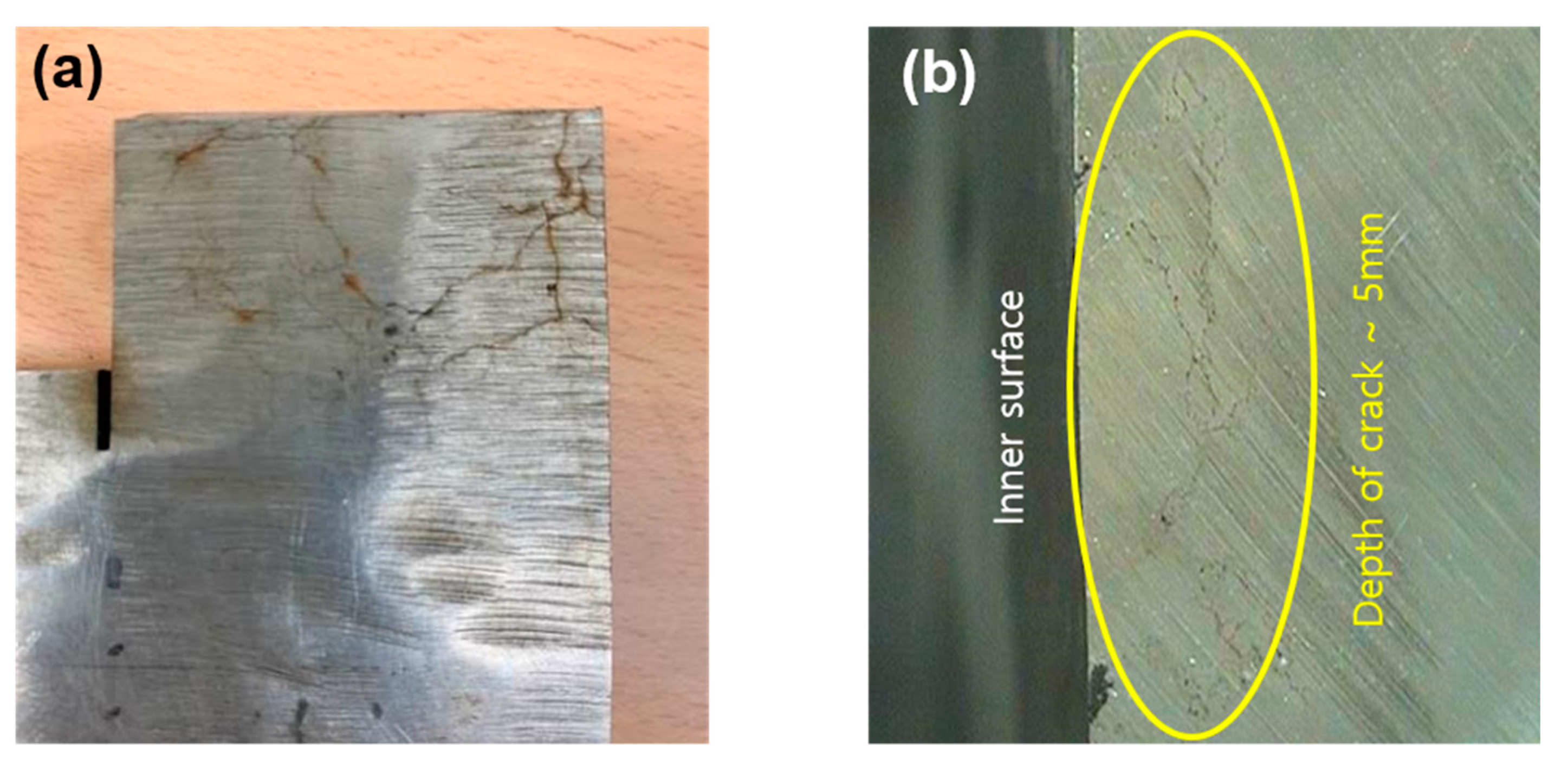
Figure 1 shows the actual reactors in the plant and the top part of the reactor top area was cut off. The bottom part of the reactor was cut off in the same way. Figure 2 shows a sample achieved from the bottom of the reactor. The thickness of the reactor was 20 mm and cracks from inner surface could be observed visually. Depth of propagation was confirmed to be approximately 5 mm, of the total thickness of the reactor.
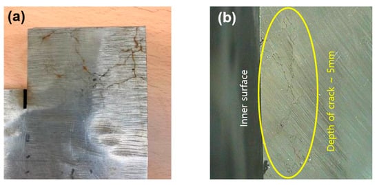
Figure 2.
(a) Photographs of the cutoff sample and (b) photographs of the cross section of the cutoff sample. Depth of the crack from the inner surface was approximately 5 mm, of wall thickness.
Chemical composition analysis was performed by using optical emission spectrometry (AMETEK™, Berwyn, IL, USA, SpectroLAB M12). Table 1 exhibits the average value obtained from five different regions from the piece of reactor wall. The metallographic sample was prepared by the hot mounting method using conductive resin. The mounted sample was polished up to 0.05 µm with colloidal silica and observed by SEM (scanning electron microscopy)-EBSD (electron back scattered diffraction). For optical microscopic analysis, Carpenter etchant was utilized. Hardness measurement was conducted using a Brinell hardness tester (Detroit Testing Company™, Lenexa, KS, USA, DLC 3100).

Table 1.
Compositions of the alloy 304 used in the experiments (in wt%).
SEM EDS (energy dispersive spectroscopy) analysis was performed by using JSM-7900F (JEOL™, Tokyo, Japan) with a 15 kV acceleration voltage. EBSD analysis was measured with Oxford Symmetry (high resolution-speed camera) and data analysis was performed using TSL OIM software. To target the area containing the tip of the micro crack, TEM (transmission electron microscopy) foils with approximately 100 nm thickness were prepared by using FIB (focus ion beam). TEM investigation was performed by using JEM 2100F (JEOL™, Tokyo, Japan) with a 200 kV acceleration voltage.
3. Results and Discussion
3.1. Microstructure of Cold Formed AISI 304 Reactor
Figure 3 shows the optical images obtained from the cross-sectioned sample along the thickness of the reactor. Multiple branched cracks with narrow gaps were observed. Morphologically, cracks were step-wise and straightforward. A distinct feature of the microstructure is that many slip bands were generated in austenite grains, which indicates that the sampling area was deformed under significant stress. A relatively dark area in the optical images represents the existence of highly dense slip bands. Regardless of location along the thickness of the bottom part of the reactor, it showed a similar density of slip bands.
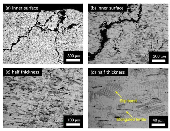
Figure 3.
(a) The microstructure obtained from bottom part of the AISI 304 reactor, which is cold formed. (a) Low magnification of the inner surface region. (b) Higher magnification image of the region in (a) shows the high density of slip bands within grains and the morphology of the crack is step-wise. (c) The microstructure of the half thickness region of the cold formed reactor and (d) enlarged image of (c), which exhibited a high density of slip bands and elongated ferrite.
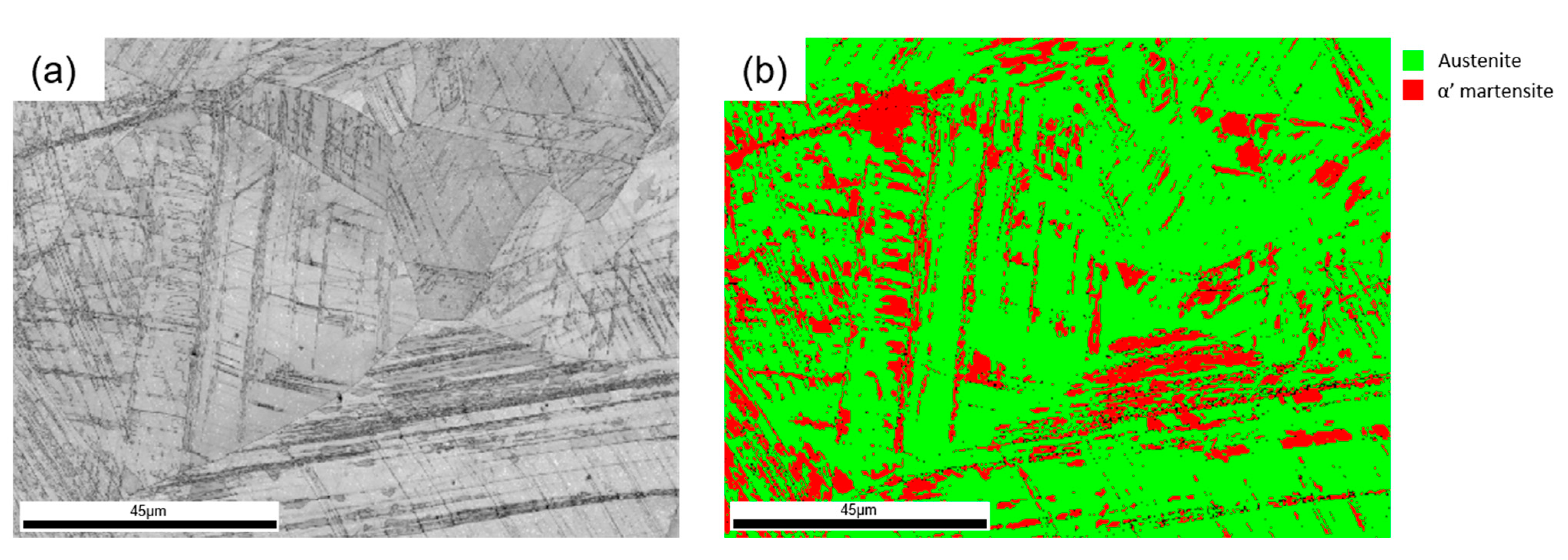
The hardness value of the cold formed reactor was determined to be about 100 HRB, which is 10% higher than that of the maximum value from the material certificate. The cause of the higher hardness was expected to be work hardening due to the cold forming process. In addition, martensitic transformation could contribute to hardening the material. It is well known that the stacking fault energy of AISI 304 stainless steel is relatively low among austenitic stainless steel and lead strain induced or stress assisted martensitic transformation occurs easily for this steel [24]. To measure a fraction of the martensite phase and observe the distribution of martensite, EBSD analysis was conducted. Figure 4 exhibits the results of EBSD analysis obtained from the middle thickness region of the cold formed reactor. Similar to optical microscopic observation, the slip bands with high density were formed. A relatively dark area in the quality image shown in Figure 4a corresponded to the α′ martensite phases obtained in the phase map. Approximately 20% of the α′ martensite phases were formed along the slip bands within the grains. On the other hand, no martensite phase was observed at the grain boundaries.
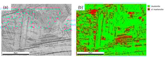
Figure 4.
(a) Image quality map obtained from half thickness region of the cold formed reactor by using electron back scattered diffraction (EBSD) analysis and (b) phase map of the region (a).
3.2. Microstructural Evidence of Cl induced Stress Corrosion Cracking
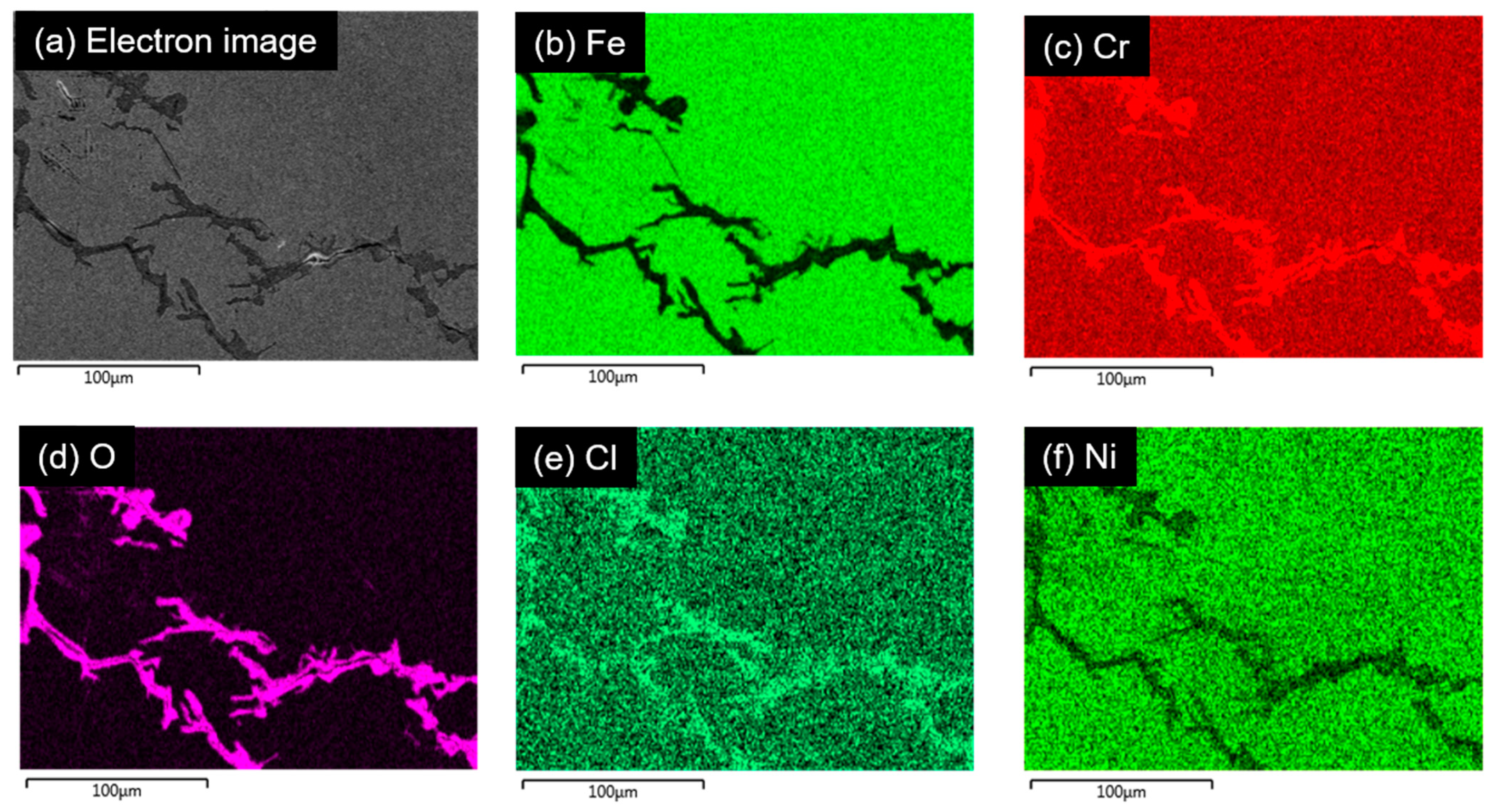
Figure 5 exhibits the results of the EDS mapping on the cracked area. The microstructure of the cracked area confirmed that the cause of the crack was Cl-SCC. Branched type cracks were observed and the oxide films formed in the gap of cracks with Cr, O, and Cl enrichment and Fe and Ni deficiency. It is presumed that the Cr-rich oxide was formed after the bare matrix had been exposed to the crack solution containing Cl ions and metal ions transported from the matrix at the crack wall. In addition, EBSD (electron back scattered diffraction) analysis was performed to reveal the path of crack propagation.
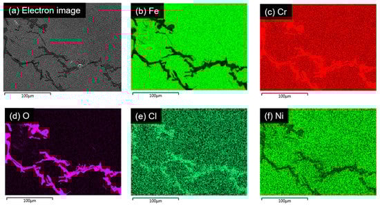
Figure 5.
Elemental distribution maps obtained from the cracked area. From top left to bottom right, secondary electron image (a), elemental distribution maps of (b) Fe, (c) Cr, (d) O, (e) Cl, and (f) Ni. The gap generated by the crack is filled with Cr-rich oxide and the Cl element is also enriched at the oxide region.
Figure 6 shows that the type of crack is transgranular. The image quality map exhibits the main crack and branches outgrow along slip bands or α’ martensite phase. The main crack propagates thorough austenitic grains as shown in the orientation map (Figure 6b). According to the result of the phase map in Figure 6c, the fraction of α′ martensite was approximately 10% in this cracked region. Additionally, there was a clear tendency that α′ martensite phases were nucleated along the slip bands. In details, branched cracks around the main crack seemed to be parallel to the slip bands and it was straightforward within grains. The main crack was also straightforward within grains and changed direction where it crossed the grain boundaries. It is expected that the crack propagates along either the slip bands or α′ martensite phase. As is well known in the fcc crystal system, slip bands formed along {111} of austenite as shown in Figure 6d. Figure 6e shows the result of the kernel average misorientation (KAM) map. KAM provides information on lattice distortion and localized deformation and a high KAM value indicates high density dislocation [25]. In accordance with the KAM map, the local misorientation indicated by the green to red region corresponds to the geometrically necessary dislocations (GND) induced by the martensitic formation. It seems that high density dislocation generated by the phase transformation contributes to the occurrence of SCC. Recently, it has been reported that high local misorientation is one of the possible sites for the initiation of cracking [26,27], which corresponded to the present experimental results.

Figure 6.
(a) Image quality map, (b) orientation map, (c) phase map obtained from the cracked area based on EBSD and (d) enlarged image indicated with red rectangle in (a) shows {111} slip traces denoted by the red line. (e) KAM map exhibits high local strain at the interface between martensite and austenite and crack tends to propagate along that region.
3.3. Preferential Site for Crack Propagation: Martensitic Transformation
Additionally, TEM analysis was conducted to obtain detailed information of the crack propagation. Figure 7 illustrates the microstructure of the tip of the micro crack. To prepare a specimen containing the tip of the micro crack, the area with a branched crack was selected, as shown in Figure 7a. Cr-rich oxide was observed and it seems the crack propagation was hindered by facing a micro twin, which is normal for the crack growth direction. Figure 7f,g shows the electron diffraction pattern obtained from the region denoted by A and M in Figure 7e, respectively. Since the width of the band was smaller than the selected area aperture, the nano beam diffraction mode was utilized with a 1 nm beam size. The region denoted by the yellow arrow and dotted lines in Figure 7e was determined to be an ε martensite phase. It is presumed that the direction of crack propagation changed to the ε martensite phase. Although the crack width narrowed during milling by FIB, altered crack path is clearly shown in Figure 7a as denoted by the yellow arrow. The ε martensite phase is known to be an intermediate phase between austenite and α′ martensite [28] and it is able to form considering that the low SFE (stacking fault energy) of AISI 304 stainless steel and cold forming process possess both strain and stress assisted martensitic transformation. However, it was confirmed that most of the martensite phase was an α′ martensite phase based on the previous result of EBSD analysis. It seems that the region with ε martensite was coincidentally selected for the TEM foil.
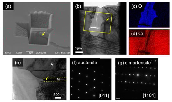
Figure 7.
TEM foil is achieved from the area contains tip of micro crack shown in (a). (b) TEM BF image obtained from area (a). (c,d) EDS map obtained from region indicated with yellow box in (b). It shows Cr rich oxide. (e) Enlarged image of (b) shows that the crack changes direction along specific band. (f,g) Nano beam electron diffraction pattern obtained from region denoted by A and M in (e), respectively.
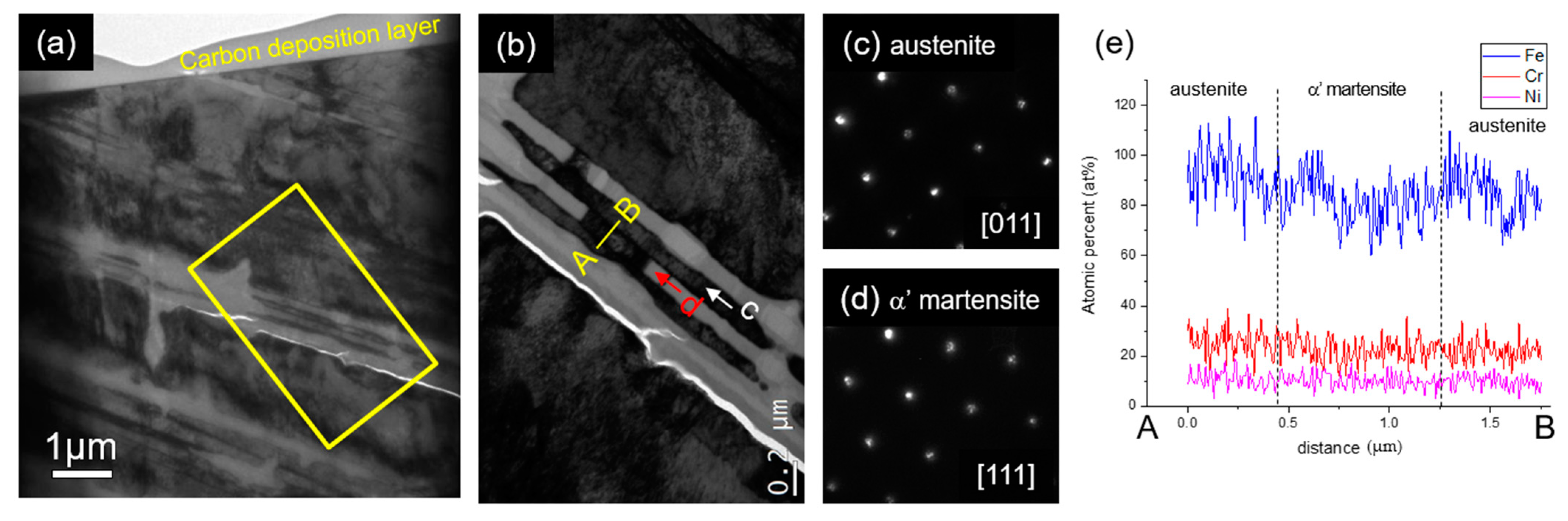
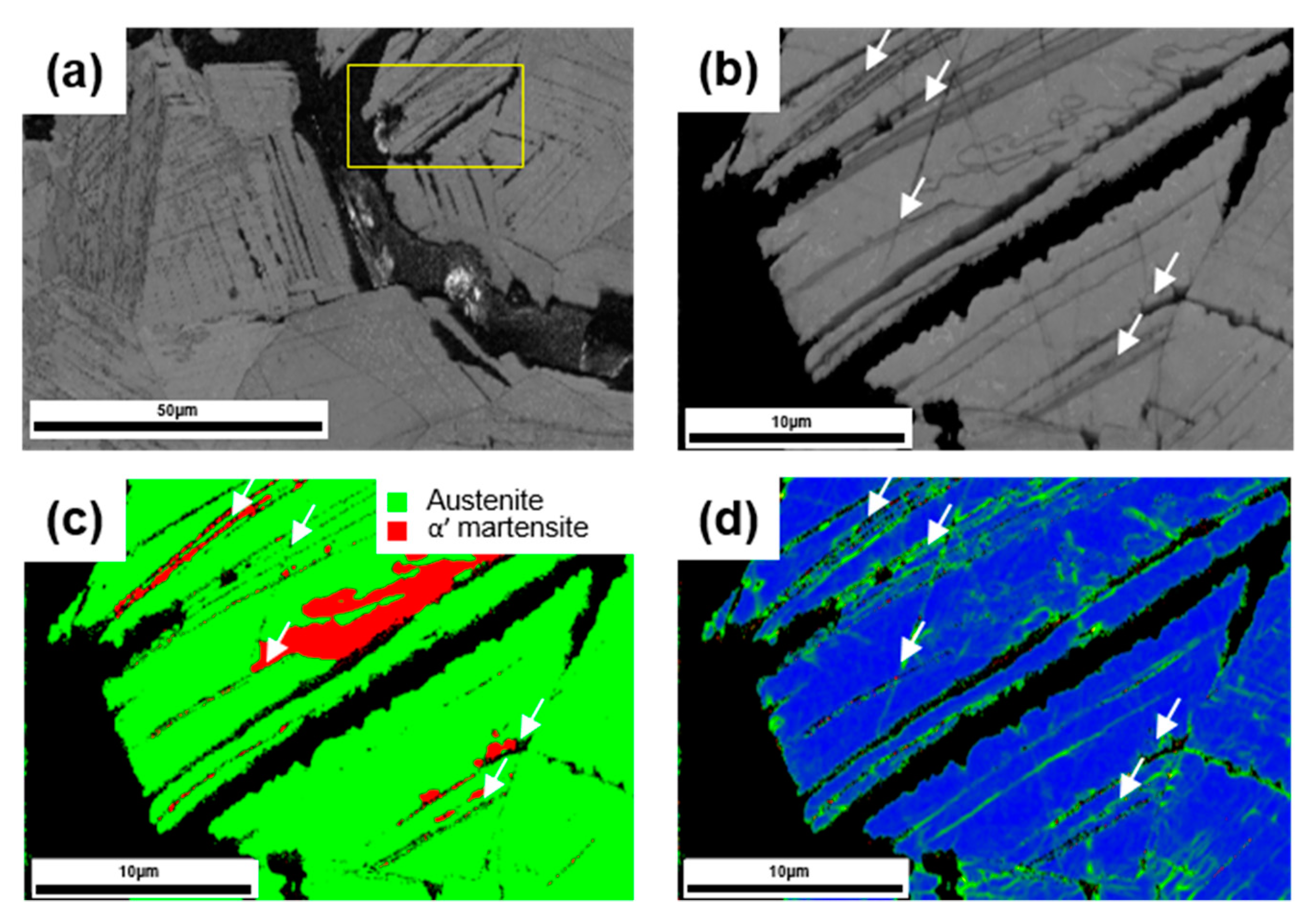
To check how the crack propagated in the area with the α’ martensite phase, an additional TEM sample was prepared, as shown in Figure 8. It can be clearly seen that oxide as a corrosion product formed parallel to the slip bands. Figure 8b illustrates the detailed microstructure of the corroded area. There were some regions not yet dissolved, as denoted with “c” in Figure 8b and it was confirmed as the austenite phase by interpreting the nano beam electron diffraction pattern shown in Figure 8c. Fortunately, we found some residue that had not corroded yet on the corrosion product and is indicated with “d” in Figure 8b. The indexing result from the electron diffraction pattern shown in Figure 8d confirms that it was α′ martensite. Based on the result of detailed microstructure analysis, the main path of crack propagation is confirmed to be α′ martensite. The chemical composition of the austenite and α’ martensite phase were measured along the interface between austenite and α′ martensite, as shown in Figure 8e. There was no distinctive difference in the chemical composition between the two phases. Considering negligible compositional difference, the main driving force of crack propagation is thought to be local strain induced by phase transformation. Figure 9 shows the magnified EBSD analyses of branch cracks in Figure 6a. Dark areas in all maps are considered to be cracks due to no signals of the Kikuchi patterns. Focused branched cracks are indicated as white arrows in Figure 9b–d, which were not fully opened yet, but about to be propagated. Comparing the phase map and KAM, we could reconfirm that the path for crack corresponded to high local strain region where small α’ martensite phases were formed.
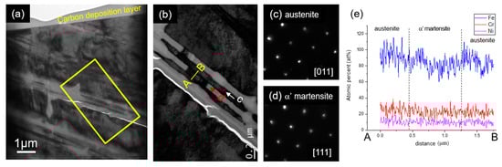
Figure 8.
Low magnification BF TEM image is obtained from the area with micro crack. (b) TEM BF image enlarged from the region indicated by yellow rectangle in (a). (c,d) Electron diffraction pattern obtained from regions denoted by c and d in (b), respectively. (e) Line profile of the chemical composition obtained along the austenite/α’ martensite/austenite indicated with A-B in (b).
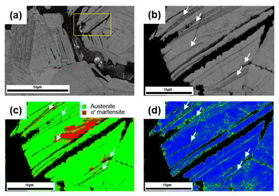
Figure 9.
(a) Image quality map cropped in Figure 6a, (b–d) image quality map and phase map and KAM obtained from yellow rectangle in (a), respectively, and white arrows indicate branched cracks.
4. Conclusions
We investigated the reactor with inner-surface cracks that had been serviced and exposed under a high temperature MgCl2 solution. Based on analyzing the microstructure of the cracked area and detailed microstructure of crack tip, the effect of cold working on the SCC of AISI 304 stainless steel and the propagation path of the crack in the cold formed region was studied. The following conclusions were able to be drawn:
- Microstructure of the cold formed AISI 304 stainless steel reactor was determined by using microscopy. It was revealed that high density slip bands were formed in the grains and along the slip bands, where 10–20% of the austenite phase transformed into α’ martensite phases due to severe cold working.
- Microstructure of the cracked area of the reactor was investigated. Based on the Cr-rich oxide layer with Cl enrichment, it was confirmed that the crack was generated by Cl-SCC. The crack propagated in transgranular mode and was parallel to the slip bands within austenitic grains.
- Microstructure of the crack tip of micro cracks was studied by using TEM analysis. It was revealed that the crack propagated along the interface between α’ martensite and austenite where high local misorientation exists within grains.
- It was revealed that Cl-SCC occurred only at the bottom part of the reactor due to martensitic transformation induced by cold-forming. Since α′ martensite could act as a highway for the propagation of Cl-SCC, strain-induced transformation needs to be suppressed to prevent shortening the life of the PVC reactor.
- Recurrence of Cl-SCC could be prevented by post heat treatment or thermo-forming. The phase fraction of α′ martensite could be reduced by post heat treatment after cold-forming. The reverse transformation from α’ martensite to γ austenite was in the range of 550 ° to 650 °C.
Author Contributions
Conceptualization, I.P.; Analysis, I.P. and E.-Y.K.; Writing—original draft preparation, I.P.; Writing—review and editing, I.P. and W.-J.Y.; Project administration, W.-J.Y. All authors have read and agreed to the published version of the manuscript.
Funding
This work was supported by the Korean Ministry of Science and ICT (Project No. PNK 7120).
Acknowledgments
The authors would like to thank Jong-Pil Kim for providing valuable specimens.
Conflicts of Interest
The authors declare no conflict of interest.
References
- Torchio, S. Stress corrosion cracking of type aisi 304 stainless steel at room temperature; influence of chloride content and acidity. Corros. Sci. 1980, 20, 555–561. [Google Scholar] [CrossRef]
- Speidel, M.O. Stress corrosion cracking of stainless steels in NaCl solutions. Metall. Trans. A 1981, 12, 779–789. [Google Scholar] [CrossRef]
- Maier, I.A.; Manfredi, C.; Galvele, J.R. The stress corrosion cracking of an austenitic stainless steel in HCl + NaCl solutions at room temperature. Corros. Sci. 1985, 25, 15–34. [Google Scholar] [CrossRef]
- Nakayama, T.; Takano, M. Application of a slip dissolution-repassivation model for stress corrosion cracking of AISI 304 stainless steel in a boiling 42% MgCl2 solution. Corrosion 1986, 42, 10–15. [Google Scholar] [CrossRef]
- Nishimura, R.; Kudo, K. Stress corrosion cracking of AISI 304 and AISI 316 austenitic stainless steels in HCl and H2SO4 solutions—Prediction of time-to-failure and criterion for assessment of SCC susceptibility. Corrosion 1989, 45, 308–316. [Google Scholar] [CrossRef]
- Alyousif, O.M.; Nishimura, R. The effect of test temperature on SCC behavior of austenitic stainless steels in boiling saturated magnesium chloride solution. Corros. Sci. 2006, 48, 4283–4293. [Google Scholar] [CrossRef]
- Alyousif, O.M.; Nishimura, R. The stress corrosion cracking behavior of austenitic stainless steels in boiling magnesium chloride solutions. Corros. Sci. 2007, 49, 3040–3051. [Google Scholar] [CrossRef]
- Kain, V. Stress corrosion cracking (SCC) in stainless steels. In Stress Corrosion Cracking; Raja, V.S., Shoji, T., Eds.; Woodhead Publishing: Cambridge, UK, 2011; pp. 199–244. [Google Scholar] [CrossRef]
- Rao, T.S.; Nair, K.V.K. Microbiologically influenced stress corrosion cracking failure of admiralty brass condenser tubes in a nuclear power plant cooled by freshwater. Corros. Sci. 1998, 40, 1821–1836. [Google Scholar] [CrossRef]
- Abedi, S.S.; Abdolmaleki, A.; Adibi, N. Failure analysis of SCC and SRB induced cracking of a transmission oil products pipeline. Eng. Fail. Anal. 2007, 14, 250–261. [Google Scholar] [CrossRef]
- Suresh Kumar, M.; Sujata, M.; Venkataswamy, M.A.; Bhaumik, S.K. Failure analysis of a stainless steel pipeline. Eng. Fail. Anal. 2008, 15, 497–504. [Google Scholar] [CrossRef]
- Sadeghi Meresht, E.; Shahrabi Farahani, T.; Neshati, J. Failure analysis of stress corrosion cracking occurred in a gas transmission steel pipeline. Eng. Fail. Anal. 2011, 18, 963–970. [Google Scholar] [CrossRef]
- Xu, S.; Zhao, Y. Using FEM to determine the thermo-mechanical stress in tube to tube–sheet joint for the SCC failure analysis. Eng. Fail. Anal. 2013, 34, 24–34. [Google Scholar] [CrossRef]
- Ling, X.; Ni, H.F.; Ma, G. Investigation of the influence of shot peening on stress corrosion cracking of stainless steel welded joints. Mater. Sci. Forum 2008, 575–578, 672–677. [Google Scholar] [CrossRef]
- Ling, X.; Ma, G. Effect of ultrasonic impact treatment on the stress corrosion cracking of 304 stainless steel welded joints. J. Press. Vessel Technol. 2009, 131. [Google Scholar] [CrossRef]
- Lu, J.Z.; Luo, K.Y.; Yang, D.K.; Cheng, X.N.; Hu, J.L.; Dai, F.Z.; Qi, H.; Zhang, L.; Zhong, J.S.; Wang, Q.W.; et al. Effects of laser peening on stress corrosion cracking (SCC) of ANSI 304 austenitic stainless steel. Corros. Sci. 2012, 60, 145–152. [Google Scholar] [CrossRef]
- Zhiming, L.; Laimin, S.; Shenjin, Z.; Zhidong, T.; Yazhou, J. Effect of high energy shot peening pressure on the stress corrosion cracking of the weld joint of 304 austenitic stainless steel. Mater. Sci. Eng. A 2015, 637, 170–174. [Google Scholar] [CrossRef]
- Cochran, R.W.; Staehle, R.W. Effects of surface preparation on stress corrosion cracking of type 310 stainless steel in boiling 42% magnesium chloride. Corrosion 1968, 24, 369–378. [Google Scholar] [CrossRef]
- Truman, J.E. The effect of composition and structure on the resistance to stress corrosion cracking of stainless steel. In Effects of Environment on Material Properties in Nuclear Systems; Thomas Telfold: London, UK, 1971. [Google Scholar]
- García, C.; Martín, F.; Tiedra, P.D.; Heredero, J.A.; Aparicio, M.L. Effects of prior cold work and sensitization heat treatment on chloride stress corrosion cracking in type 304 stainless steels. Corros. Sci. 2001, 43, 1519–1539. [Google Scholar] [CrossRef]
- Barbucci, A.; Cerisola, G.; Cabot, P. Effect of cold-working in the passive behavior of 304 stainless steel in sulfate media. J. Electrochem. Soc. 2002, 149. [Google Scholar] [CrossRef]
- Kain, V.; Chandra, K.; Adhe, K.N.; De, P.K. Effect of cold work on low-temperature sensitization behaviour of austenitic stainless steels. J. Nucl. Mater. 2004, 334, 115–132. [Google Scholar] [CrossRef]
- Scatigno, G.G.; Ryan, M.P.; Giuliani, F.; Wenman, M.R. The effect of prior cold work on the chloride stress corrosion cracking of 304L austenitic stainless steel under atmospheric conditions. Mater. Sci. Eng. A 2016, 668, 20–29. [Google Scholar] [CrossRef]
- Lee, W.-S.; Lin, C.-F. Impact properties and microstructure evolution of 304L stainless steel. Mater. Sci. Eng. A 2001, 308, 124–135. [Google Scholar] [CrossRef]
- Calcagnotto, M.; Ponge, D.; Demir, E.; Raabe, D. Orientation gradients and geometrically necessary dislocations in ultrafine grained dual-phase steels studied by 2D and 3D EBSD. Mater. Sci. Eng. A 2010, 527, 2738–2746. [Google Scholar] [CrossRef]
- Saravanan, N.; Karamched, P.S.; Liu, J.; Rainasse, C.; Scenini, F.; Lozano-Perez, S. Using local GND density to study SCC initiation. Ultramicroscopy 2020, 217, 113054. [Google Scholar] [CrossRef]
- Zhang, W.; Wu, H.; Wang, S.; Hu, Y.; Fang, K.; Wang, X. Investigation of stress corrosion cracking initiation in machined 304 austenitic stainless steel in magnesium chloride environment. J. Mater. Eng. Perform. 2020, 29, 191–204. [Google Scholar] [CrossRef]
- Cayron, C.; Barcelo, F.; Carlan, Y.d. The mechanisms of the fcc–bcc martensitic transformation revealed by pole figures. Acta Mater. 2010, 58, 1395–1402. [Google Scholar] [CrossRef]


Publisher’s Note: MDPI stays neutral with regard to jurisdictional claims in published maps and institutional affiliations. |
© 2020 by the authors. Licensee MDPI, Basel, Switzerland. This article is an open access article distributed under the terms and conditions of the Creative Commons Attribution (CC BY) license (http://creativecommons.org/licenses/by/4.0/).