Article

Enhancement of Balance in Strength, Ductility, and Stretch Flangeability by Two-Step Austempering in a 1000 MPa Grade Cold Rolled Bainitic Steel

State Key Laboratory of Rolling and Automation, Northeastern University, Shenyang 110819, China
*
Authors to whom correspondence should be addressed.
Metals 2021, 11(1), 96; https://doi.org/10.3390/met11010096
Submission received: 7 December 2020 / Revised: 30 December 2020 / Accepted: 31 December 2020 / Published: 6 January 2021
(This article belongs to the Section Metal Casting, Forming and Heat Treatment)

Abstract

:
The microstructural evolution and properties for varied austempering routes are investigated in a cold-rolled bainitic steel. Special attention is given to the effect of retained austenite (RA) in terms of its fraction, carbon concentration, and morphology resulting from different austempering routes on mechanical properties and stretch flangeability. Bimodal sized bainitic laths are provided, and the carbon concentration of RA maintains the highest value through the two-step austempering. Total elongation (TEL) is remarkably enhanced for the two-step austempering, deviating from the exponential relationship between tensile strength (TS) and TEL as maintained by the one-step austempering. Considering the two plateaus of the strain-hardening exponent, it is considered that the hierarchical stability of RA is provided by the two-step austempering, leading to the postponed necking point so as to improve the uniform elongation. Two-step austempering could provide more complete bainitic transformation as well as more stable film-like RA, supplying a promising way to improve the combination of strength, ductility, and stretch flangeability.

1. Introduction

The application of high-strength steel is one of the most effective ways to reduce car body weight while ensuring the required safety. The multiphased steels with a combination of varied phases, such as ferrite, martensite/bainite, and retained austenite (RA) are developed to satisfy the demand of structural parts. Among them, bainitic steels are attractive because of their good combination of strength and ductility. It is well accepted that the bainitic lath size, which is determined by the transformation temperature, strongly affects the strength. For instance, Sandvik et al. [1] found that strength can be obviously increased by refining the bainitic lath size through decreasing the austempering temperature. Bhadeshia et al. [2,3] developed an ultra-high strength bainitic steel with an excellent balance of strength and ductility (tensile strength higher than 2000 MPa and total elongation higher than 20%) by refining the bainitic lath to tens of nanometers through a low-temperature austempering treatment. Furthermore, remarkable ductility is provided due to a considerable fraction of RA by means of the transformation of metastable austenite into martensite, i.e., the transformation-induced plasticity (TRIP) effect.
In addition, it is considered that the hardness difference between the soft and hard phase can be avoided in bainitic steels, so that ensures the excellent combination of strength and local formability [4,5,6] through retarding the strain localization. It is reported that a certain fraction of RA with relatively high stability is important for the improvement of the stretch flangeability, because it can suppress the strain-induced transformation in the punched hole-surface layer before hole expansion and consequently improve the localized ductility on hole-expanding through the superior TRIP effect [7]. Therefore, it is crucial to maintain a good balance of strength, ductility, and local formability by optimizing the bainitic lath size as well as the fraction and stability of RA.
The fraction of RA can be increased through increasing the austempering temperature. However, this is at the expense of the strength decreasing [8]. Hase et al. [9] obtained a bimodal size distributed bainitic microstructure through a two-step austempering in which blocks of austenite were refined and the RA was further stabilized, achieving a much higher combination of strength, ductility, and fracture toughness than the one-step counterparts. Xie et al. [10] reported that a two-step austempering could further stabilize the RA, leading to a significant increase in ductility as well as a strength–ductility balance.
In this study, we have studied the effect of austempering treatment in terms of temperature and holding time on the microstructure, mechanical properties, and stretch flangeability. Comparison of the fraction of RA and its stability and properties was made between one-step and two-step austempering treatment. The role of RA on work-hardening behavior, failure behavior during hole expansion, and on a combination of strength, ductility, and stretch flangeability was elucidated.

2. Materials and Methods

The chemical composition of the experimental steel is listed in Table 1. The steel was melted under vacuum in an induction furnace (North Electric Furnace Factory, Jinzhou, China) and cast as ingots. The addition of relatively high Si is expected to suppress the precipitation of cementite during bainite transformation, with an indirect effect on the stabilization of austenite through the carbon enrichment of austenite as a result of the fact that Si has very low solubility in cementite. It should be noted that Si can be partially or completely replaced by Al and/or P considering their similar effect [11,12,13,14]. Nb was added to enhance grain refinement.
Aluminum is well known for its ability to hinder the carbide precipitation similar to silicon; besides, it increases the stability of retained austenite [8]. In addition, the main feature of using aluminum is that it represents much better surface quality compared to silicon.
The ingot was hot forged into blocks with a thickness of 50 mm. After austenitization at 1200 °C for 2 h, the block was hot rolled to plate of thickness ≈4.5 mm via 7 passes and the finish rolling temperature was about 900 °C, which was followed by accelerated cooling to 600 °C with subsequent air cooling to room temperature.
The hot-rolled plates were further cold rolled to 1.2 mm with a total rolling reduction of 73.3%. The dilatometric samples were machined from the cold-rolled plate (4 mm × 10 mm) and were performed on a DIL 805 dilatometer (Bähr, Germany) to investigate the microstructural evolution during austempering. The thermocouples were spot-welded at the center as well as at the end of the sample to monitor the temperature homogeneity. Austenization at 950 °C for 180 s was adopted. The Ms temperature under this condition is 364 °C. In order to investigate the influence of austempering parameters on properties, a continuous annealing experiment was carried out using a CAS300-II continuous annealing simulator (RAL, Shenyang, China). The austempering is carried out at 370 °C and 400 °C for 50–500 s. In addition, a two-step austempering is adopted, where the austempering temperature is 370 °C and 400 °C for the first and second step, respectively. The schematic diagrams of the detailed experimental parameters are shown in Figure 1.
To examine the microstructure, specimens were mechanically polished and etched with 2% nital solution and observed using Zesis Ultra 55 field emission gun scanning electron microscope (FEG-SEM, Carl Zeiss AG, Jena, Germany). For TEM studies, samples were cut into 500 μm thick slices and mechanically ground to a thickness of 50 μm. Disks of 3 mm diameter were punched and electropolished in Struer’s Tenupol twin-jet polisher (Struers, Willich, Germany) using a solution of 93% alcoholic solution and 7% perchloric acid. The foils were observed in FEI TecnaiG2 F20 transmission electron microscope (FEI, OR, USA) at an operating voltage of 200 kV. The electron backscattered diffraction (EBSD) studies were carried out in FEG-SEM for automatic orientation mapping with a 0.07 μm step size. EBSD data were processed by HKL CHANNEL 5 software (Oxford company, Abingdon-on-Thames, UK). Quantitative X-ray diffraction was carried out to determine the volume fraction of RA (Vγ) and its carbon concentration (Cγ). The samples were electropolished using the aforementioned method and were scanned with a Bruker D8 X-ray diffractometer (XRD, Bruker AXS Inc., USA) at a step size of 0.02° and a count time of 1.2 s per step using Co-Kα radiation. The (200) and (220) diffraction peaks of austenite and (200) and (211) diffraction peaks of ferrite were selected to calculate the Vγ [15]. The multiple diffraction peaks were combined to minimize the influence of preferred orientation. The equation aγ = 3.556 + 0.0453Cγ was used to calculate Cγ (wt %) in RA [16], where aγ (Å) is the lattice parameter of austenite.
Tensile tests were carried out using standard rectangular specimens with a gauge length of 30 mm and a crosshead speed of 1 mm/min using a SANS 5105 testing machine (SANS, Shenzhen, China) with a 100 kN load cell. In each condition, three specimens were tested to obtain an average of mechanical properties. A hole expansion experiment was performed in a universal testing machine. A conical punch of 10 mm (d0) diameter and angle of 60° was used for these tests. To better investigated the relationship between mechanical properties and local formability, the hole was processed by using a wire electrical discharge cutting machine (BUAA, Beijing, China) to minimize the accumulated shearing damage as well as the defect such as micro-cracks caused by the conventional punching method. A speed of 3 mm/min with a blank holder force of 50 KN was used in the experiment. The hole expansion rate (HER) was calculated by the equation HER = (d – d0)/d0 × 100%, where d and d0 are the fractured hole diameter and the initial hole diameter, respectively.

3. Results and Discussion

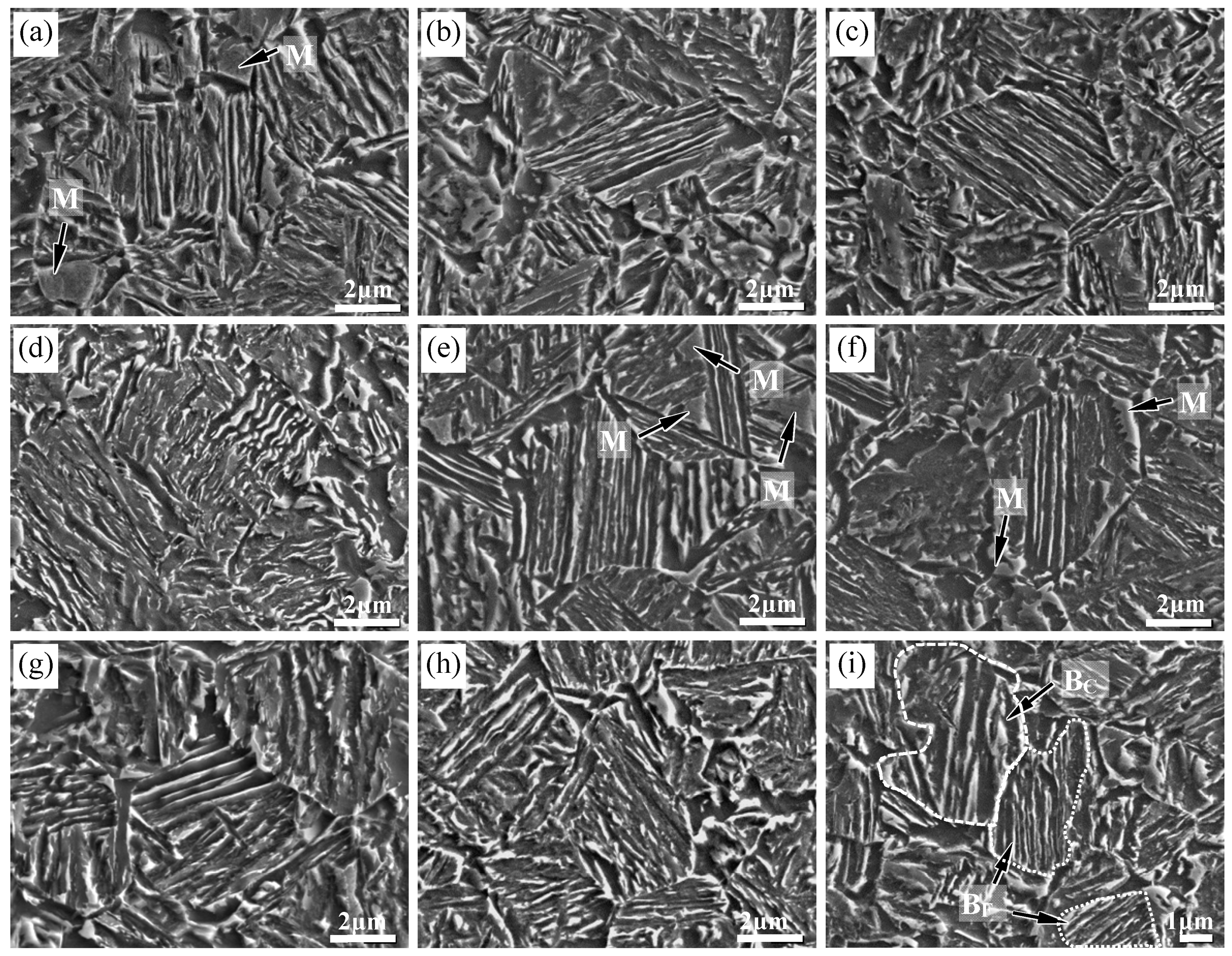
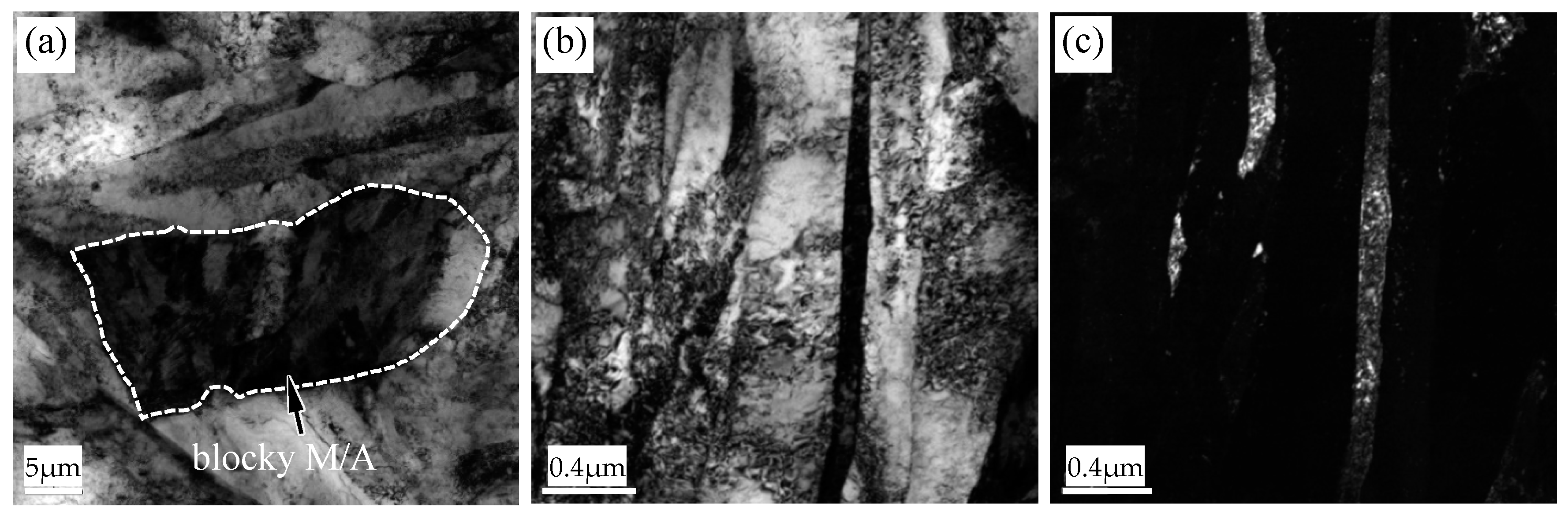
3.1. Microstructural Characterization

Figure 2 shows the SEM micrographs of specimens austempered at 370 °C and 400 °C for 50–500 s. For both austempering temperature, the microstructure mainly displays lath morphology. Blocky martensite islands (marked with white arrows) are observed for the holding time of 50 s (Figure 2a,e), which were formed from untransformed austenite during subsequent cooling after austempering. When the austempering time increases to 180 s, the amount and size of the blocky martensite is obviously decreased but still can be found, especially for 400 °C austempering (shown with white arrows in Figure 2f). The microstructure is similar for 250 s and 500 s austempering, implying that the bainite transformation is completed up to 250 s. In addition, the width of the bainitic lath as well as the interlath film-like retained austenite/martensite (RA/M) seems wider for 400 °C austempering. For the two-step sample (Figure 2i), one can see a refined microstructure with lath morphology, similar with that in Figure 2e. In addition, a coarser lath microstructure with wider RA/M instead of large blocky martensite islands is found, which is considered to result from the bainitic transformation at 400 °C.
Figure 3 shows the image quality map with RA distribution measured by EBSD for 400 °C austempering with a holding time of 50 s and 250 s and two-step austempering. It is found that for the holding time of 50 s, the detected amount of RA is low with blocky morphology (Figure 3a). As the holding time increases to 250 s (Figure 3b), the amount of RA is remarkably increased, and the RA particles tend to display a rod-like shape. For the two-step austempering (Figure 3c), the morphology of RA is alike with that in Figure 3b, but it seems that more thin film-like RA exists in the microstructure.
Figure 4 shows the TEM morphology of blocky martensite and film-like RA for 50 s and 250 s austempering, respectively. In Figure 4a, blocky martensite is presented, in which twinned martensite is found, indicating the high carbon concentration. As is shown in Figure 2a,e the transformation at the holding time of 50 s is not completed. The untransformed austenite may transform to martensite due to its insufficient stabilization, and only a few fractions of austenite would be retained at room temperature. With the completion of transformation at a longer holding time, the RA with a film-like shape mainly lies between bainitic laths and blocks, as shown in Figure 4b.
Figure 5 shows Vγ and Cγ with different austempering parameters. Both Vγ and Cγ are lower for 370 °C than for 400 °C austempering. It is found that Vγ increases rapidly from 50 to 180 s, with the same trend of EBSD measurement (Figure 3a,b), and then it increases slightly and remains stable with the increasing of holding time after 180 s. Cγ also increases sharply from 50 to 180 s, resulting from the proceeding of bainitic transformation. Then, it increases gradually with the increasing of holding time, indicating the continuous carbon partitioning during the austempering. The average Vγ and Cγ for the two-step austempering is 12.2% and 1.39 wt %, respectively. The Cγ is the highest among these specimens.

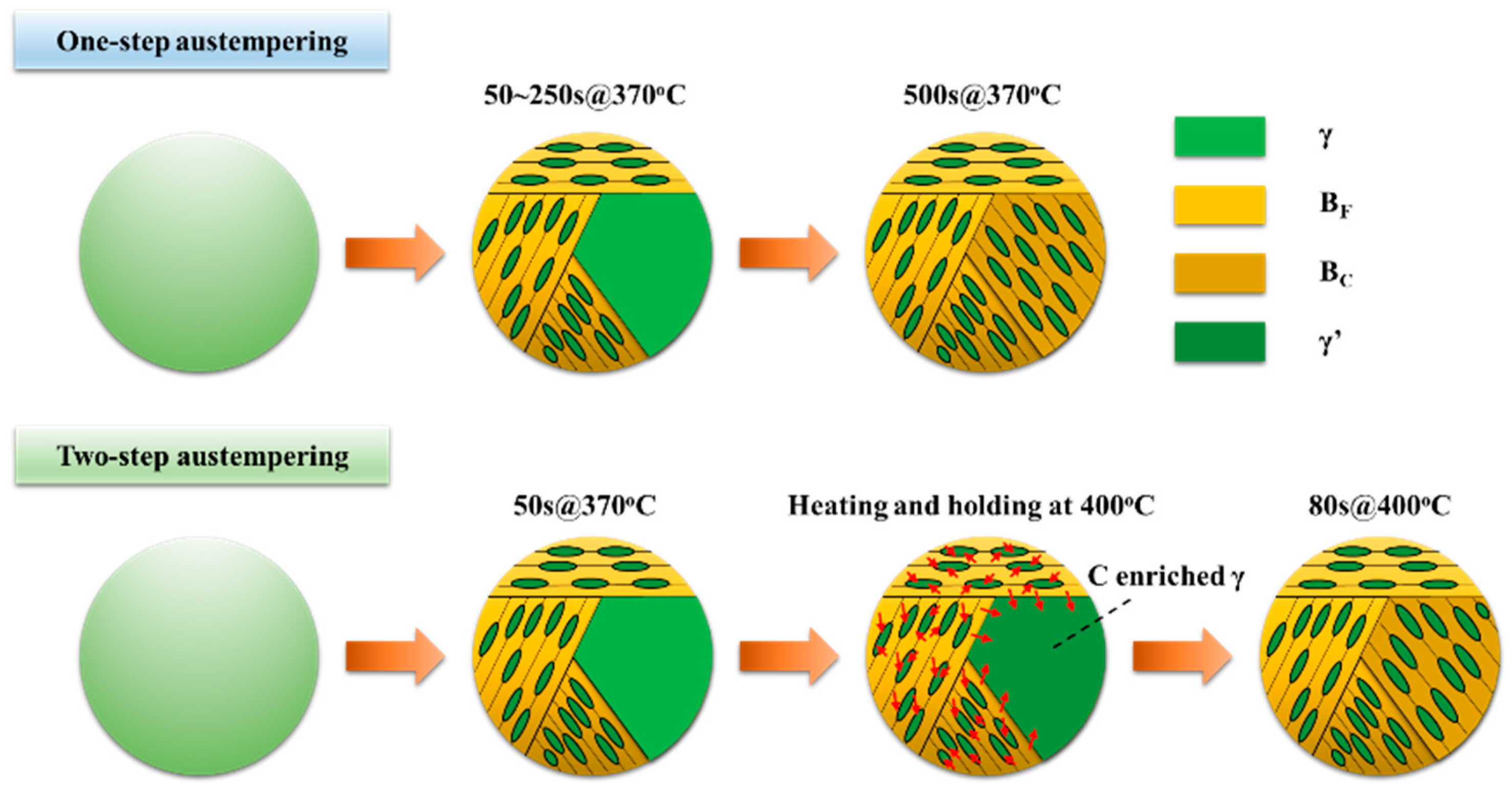
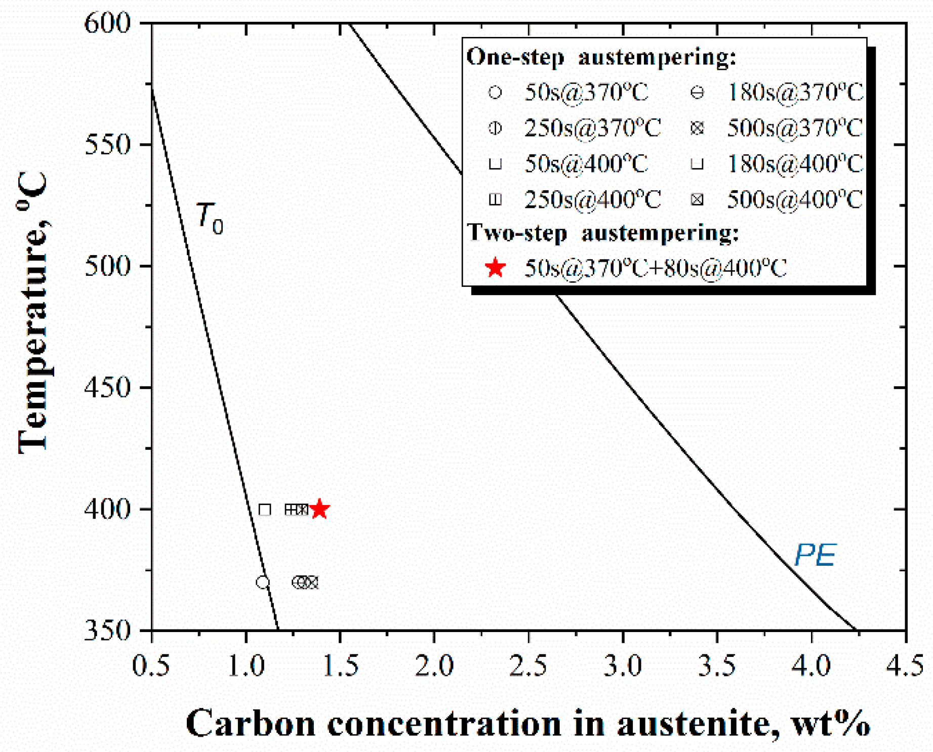
3.2. Analysis of Microstructural Evolution

For the two-step austempering process, the microstructure morphology as well as features (fraction, stability, etc.) of RA are determined by the combination of the two steps. While austempering at a lower temperature, i.e., 370 °C for 50 s (first-step) in this study, finer bainitic laths with higher defect density would be formed. Considering the relatively short holding time, austenite is partially retained at the end of the first-step austempering. In the following austempering at 400 °C (second-step), untransformed austenite further transforms into bainite with a larger lath size, and a higher proportion of austenite may be retained in this case. The schematic diagram of the microstructure evolution is shown in Figure 6. Considering the two-step bainitic transformation as well as the carbon partitioning, it is probable that the two-level stability of RA may be provided through the two-step austempering. It may include the more stable austenite obtained at 370 °C austempering, which is further stabilized by subsequent 400 °C austempering and the less stable austenite formed at 400 °C austempering.
Consequently, three items can be achieved for the microstructural optimization. Firstly, bainite transformation proceeds more completely compared to the one-step 400 °C austempering, replacing blocky M/A constituents with film-like RA. Secondly, the untransformed austenite at the end of the second-step austempering is further enriched in carbon, leading to a higher carbon concentration in the final RA compared to the 370 °C austempering for 50 and 180 s. The above two features contribute to the improvement of ductility and stretch flangeability. Thirdly, a large quantity of fine lath bainite is formed at the first step, maintaining high strength. Therefore, it is indicated that the two-step austempering process provides a good way to balance the strength, ductility, and stretch flangeability.
It is proposed that the bainite transformation ceases once the carbon concentration of austenite reaches T0 line, where the fcc (face-centered cubic) and bcc (body-centered cubic) phase with identical composition have the same free energy [17]. Figure 7 shows the T0 and PE (para-equilibrium) line calculated by Thermo-calc software (2019a version) based on the TCFE 9 database with accompanied with measured Cγ. One can see that the actual Cγ is close to the T0 line for the holding time of 50 s, and it exceeds the T0 line as the austempering time increases. Moreover, Cγ for the two-step austempering is further increased. This is attributed to the fact that carbon partitions from post-transformed bainite to austenite. In particular, carbon enrichment further occurs from lower-temperature bainitic ferrite into neighboring austenite at a higher austempering temperature, because part of the carbon atoms is usually trapped in bainitic laths with high dislocation density [18,19,20]. However, Cγ is still far from the line of PE, which is a local equilibrium for carbon, but there is no diffusion of iron and substitutional elements.

3.3. Mechanical Properties

Figure 8a shows the effects of austempering temperature and holding time on mechanical properties. For both austempering temperature, tensile strength (TS) and yield strength (YS) decrease with the increasing of austempering time, and TS slightly decreases when the holding time is longer than 250 s. Correspondingly, the total elongation (TEL) increases as the austempering time is prolonged. The higher TS as well as the lower TEL at the early stage of austempering is considered to be caused by the blocky martensite. From Figure 8b, one can see that TEL decreases continuously with the increase of TS, maintaining an exponential trend between TEL and TS for the one-step austempering process, as reported in lots of studies in the literature [8,21,22]. However, it is interesting to note that TEL is remarkably enhanced for the two-step austempering, improving the strength–ductility balance in this case.
The following formulas were used to calculate the true stress–true strain data from the engineering data obtained through tensile testing.
ε t r u e = ln ( 1 + e )
σ t r u e = σ e n g ( 1 + e )
where εtrue is true strain, σtrue is true stress, e is engineering strain, and σeng is engineering stress, and the strain hardening exponent n is calculated as:
n = d ( ln σ t r u e ) d ( ln ε t r u e )
Figure 9 shows the strain-hardening exponent versus true strain for three austempering processes. The strain-hardening exponent of three processes decreases quickly at first and then decreases with a slower rate, forming the first plateau. In the following, it decreases quickly again and then increases with a slow rate, forming the second plateau. It seems that the length of the second plateau for 370 °C austempering is shorter compared to the other two processes, which may result from the lower fraction of RA considering that the carbon concentration is close to that for 400 °C austempering.
It is interesting to note that the length of the first plateau for the two-step austempering is obviously longer than its counterparts. It is probably because most RA, on the one hand, are in a film-like shape; and on the other hand, they possess a higher carbon concentration due to adequate partitioning in the second-step austempering, both of which lead to high stability of RA. In this case, the RA could transform more gradually to martensite during straining [23,24], leading to a longer first plateau. Especially, the longer first plateaus contributed by RA allow the necking point to be postponed, improving the uniform elongation. Considering the corresponding relationship between the plateaus and RA, the existence of the two-level stability of RA provided through the two-step austempering is confirmed.

3.4. Stretch Flangeability

Figure 10a shows the HER under varied austempering temperature and time. The HER is generally higher for 400 °C than for 370 °C austempering. With the increasing of holding time, HER increases gradually for 370 °C austempering, but it remains stable for the holding time of 180 to 500 s for 400 °C austempering. The HER value is 54 ± 3% for the two-step austempering. It is reported that there is a strong correlation between HER and TS where HER decreases with the increasing of TS up to approximately 700 MPa, but it is insensitive to the change of TS for TS beyond 700 MPa [25]. Figure 10b shows the experimental data in this study along with data from the literature [18]. One can see that the data in this study bring a deviation from the trend in the strength range from 1000 to 1200 MPa. Similarly, there is also data scattering for dual phase (DP) steel in this figure. The reason is that factors that less directly affect the TS, such as the morphology of martensite [26] and hardness ratio of ferrite and martensite [6,27], also play a significant role in the HER value for DP steel. It is believed that the deviation in the TS-HER relationship for the studied steel results from the optimal combination of bainite matrix and retained austenite.
In our previous study [28], there is a linear relationship between the yield ratio (YR) and HER value, in which ferrite exists in the microstructure. However, YR in this study is similar, ranging from 0.74 to 0.76, so it is ruled out as a possible factor that may correlate with HER. In this respect, one can say that the influence of YR on HER is much more notable for a mixed microstructural constituent than a single microstructural constituent.
The TRIP effect is reported to prevent strain localization, and martensite transformation occurring at low strains tends to decrease the HER [29]. During the hole expansion test, a higher HER would be obtained through a steady and continuous transformation of RA to martensite throughout the test. Thus, the stability of RA plays a key role in stretch flangeability. It is known that stability of RA is determined by both chemical and mechanical stability [30,31,32,33,34]. The carbon concentration in the RA is responsible for its chemical stability [34,35], whereas mechanical stability is determined by other factors such as size [31], morphology [34,35,36], and the surrounding microstructure of RA [30].
Figure 11 shows SEM cross-sectional micrographs nearby the main crack in hole expansion specimens austempered at 400 °C for 50 s and 180 s. In Figure 11a,b, tiny cracks are observed among the fine bainite region with film-like RA/M (some RA may transform to martensite due to the TRIP effect during hole expanding). Crack propagation may be inhibited by TRIP effect of the film-like RA as well as by the tough film-like RA itself, which is in accordance with the research of Sugimoto et al. [4,30]. However, a large quantity of voids appears in the vicinity of blocky martensite (shown with white arrows). It is indicated that the strain incompatibility between the matrix and hard blocky martensite is the dominant cracking mechanism during hole expanding in this case. Strain partitioning to the softer matrix occurs during deformation, potentially inducing more damage to the matrix close to the hard phase, resulting in the nucleation and growth of voids in these regions [37]. Yang et al. [38] also reported that large blocky RA/M boosts the crack nucleation. The blocky martensite originated from two parts. One part is the intrinsic, which is formed during the cooling process after austempering treatment. The other part comes from the large blocky RA through the TRIP effect in the early stage of local forming deformation. This would lower the HER by early failure in the vicinity of blocky martensite through void or crack formation. Thus, tendering more complete bainitic transformation as well as more film-like RA through two-step austempering would help improve the stretch flangeability.

4. Conclusions

In this study, the microstructural evolution of the TRIP-aided bainitic steel under different austempering routes was investigated. The effect of the microstructure (bainite and RA) on the mechanical properties as well as on stretch flangeability was elucidated. The main conclusions from this work are as follows:
(1)
With the increasing of austempering temperature, the width of both bainitic lath and interlath film-like RA/M becomes wider. The bimodal bainitic lath size is provided through the two-step austempering. Both Vγ and Cγ are lower for 370 °C than for 400 °C austempering. The Cγ for the two-step austempering maintains the highest value, which is attributed to the fact that carbon enrichment further occurs from lower-temperature bainitic ferrite into neighbored austenite at higher austempering temperature in the second step of austempering.
(2)
TS and YS decrease with the increasing of austempering time, and TS slightly decreases when the holding time is longer than 250 s. TEL increases as the austempering time is prolonged. The higher TS as well as lower TEL at the early stage of austempering is caused by the blocky martensite. In contrast, TEL is remarkably enhanced for the two-step austempering, deviating from the exponential relationship between TS and TEL as maintained by the one-step austempering.
(3)
In light of the two plateaus of the strain-hardening exponent, it is considered that the two-level stability of RA exists, which is provided by the two-step austempering. The two longer plateaus allow the necking point to be postponed, improving the uniform elongation.
(4)
Strain incompatibility between the matrix and hard blocky martensite is the dominant cracking mechanism during hole expanding. Tendering more complete bainitic transformation as well as more film-like RA would help improve the stretch flangeability. The two-step austempering may be a promising way to ensure a good combination of strength, ductility, and stretch flangeability.

Author Contributions

Conceptualization, S.T. and H.L.; methodology, S.T.; experiment, S.T. and H.L.; formal analysis, S.T. and H.L.; investigation, S.T. and H.L.; writing—original draft preparation, S.T.; writing—review and editing, H.L. supervision, Z.L.; project administration, G.W. All authors have read and agreed to the published version of the manuscript.

Funding

This study was supported by the National Natural Science Foundation of China (Grant Nos. 51774083 and 51774082), the Fundamental Research Funds for the Central Universities (Grant No. N2007011), 111 Project (Grant No. B20029), and National Key Research and Development Program (Grant No. 2017YFB0304402).

Institutional Review Board Statement

Not applicable.

Informed Consent Statement

Not applicable.

Data Availability Statement

The data presented in this study are available on request from the corresponding author.

Conflicts of Interest

The authors declare no conflict of interest.

References

  1. Sandvik, B.P.J.; Nevalainen, H.P. Structure-property relationship in commercial low-alloy bainitic-austenitic steel with high strength, ductility and toughness. Met. Technol. 1981, 15, 213–220. [Google Scholar] [CrossRef]
  2. Caballero, F.G.; Bhadeshia, H.K.D.H. Very strong bainite. Curr. Opin. Solid State Mater. Sci. 2004, 8, 251–257. [Google Scholar] [CrossRef] [Green Version]
  3. Yokota, T.; García Mateo, C.; Bhadeshia, H.K.D.H. Formation of nanostructured steels by phase transformation. Scripta Mater. 2004, 51, 767–770. [Google Scholar] [CrossRef] [Green Version]
  4. Sugimoto, K.; Sakaguchi, J.; Iida, T.; Kashima, T. Stretch-flangeability of a high-strength TRIP type bainitic sheet steel. ISIJ Int. 2000, 40, 920–926. [Google Scholar] [CrossRef]
  5. Hausmann, K.; Krizan, D.; Spiradek-Hahn, K.; Pichler, A.; Werner, E. The influence of Nb on transformation behavior and mechanical properties of TRIP-assisted bainitic-ferritic sheet steels. Mater. Sci. Eng. A 2013, 588, 142–150. [Google Scholar] [CrossRef]
  6. Hasegawa, K.; Kawamura, K.; Urabe, T.; Hosoya, Y. Effects of microstructure on stretch-flange-formability of 980 MPa grade cold-rolled ultra high strength steel sheets. ISIJ Int. 2004, 44, 603–609. [Google Scholar] [CrossRef]
  7. Sugimoto, K.; Iida, T.; Sakaguchi, J.; Kashima, T. Retained austenite characteristics and tensile properties in a TRIP type bainitic sheet steel. ISIJ Int. 2000, 40, 902–908. [Google Scholar] [CrossRef]
  8. Zhao, J.; Lv, B.; Zhang, F.; Yang, Z.; Qian, L.; Chen, C.; Long, X. Effects of austempering temperature on bainitic microstructure and mechanical properties of a high-C high-Si steel. Mater. Sci. Eng. A 2019, 742, 179–189. [Google Scholar] [CrossRef]
  9. Hase, K.; Garcia-Mateo, C.; Bhadeshia, H.K.D.H. Bimodal size-distribution of bainite plates. Mater. Sci. Eng. A 2006, 438–440, 145–148. [Google Scholar] [CrossRef] [Green Version]
  10. Xie, Z.J.; Ren, Y.Q.; Zhou, W.H.; Yang, J.R.; Shang, C.J.; Misra, R.D.K. Stability of retained austenite in multi-phase microstructure during austempering and its effect on the ductility of a low carbon steel. Mater. Sci. Eng. A 2014, 603, 69–75. [Google Scholar] [CrossRef]
  11. Jacques, P.J.; Girault, E.; Mertens, A.; Verlinden, B.; van Humbeeck, J.; Delannay, F. The Developments of cold-rolled TRIP-assisted multiphase steels. Al-alloyed TRIP-assisted multiphase steels. ISIJ Int. 2001, 41, 1068–1074. [Google Scholar] [CrossRef]
  12. De Meyer, M.; Vanderschueren, D.; De Cooman, B.C. The influence of the substitution of Si by Al on the properties of cold rolled C-Mn-Si TRIP steels. ISIJ Int. 1999, 39, 813–822. [Google Scholar] [CrossRef]
  13. Soliman, M.; Weidenfeller, B.; Palkowski, H. Metallurgical phenomena during processing of cold rolled TRIP steel. Steel Res. Int. 2009, 80, 57–65. [Google Scholar]
  14. Barbé, L.; Verbeken, K.; Wettinck, E. Effect of the addition of P on the mechanical properties of low alloyed trip steels. ISIJ Int. 2006, 46, 1251–1257. [Google Scholar] [CrossRef] [Green Version]
  15. Luzginova, N.; Zhao, L.; Sietsma, J. Evolution and thermal stability of retained austenite in SAE 52100 bainitic steel. Mater. Sci. Eng. A 2007, 448, 104–110. [Google Scholar] [CrossRef]
  16. Jimenez-Melero, E.; van Dijk, N.H.; Zhao, L.; Sietsma, J.; Offerman, S.E.; Wright, J.P.; van der Zwaag, S. Characterization of individual retained austenite grains and their stability in low-alloyed TRIP steels. Acta Mater. 2007, 55, 6713–6723. [Google Scholar] [CrossRef]
  17. Bhadeshia, H.K.D.H. Bainite in Steels: Transformation, Microstructure and Properties, 2nd ed.; Institute of Materials: London, UK, 2001; p. 9. [Google Scholar]
  18. Garcia-Mateo, C.; Caballero, F.G.; Bhadeshia, H.K.D.H. Acceleration of low-temperature bainite. ISIJ Int. 2003, 43, 1821–1825. [Google Scholar] [CrossRef] [Green Version]
  19. García-Mateo, C.; Caballero, F.G.; Bhadeshia, H.K.D.H. Mechanical properties of low-temperature bainite. Mater. Sci. Forum 2005, 500–501, 495–502. [Google Scholar]
  20. Peet, M.; Babu, S.S.; Miller, M.K.; Bhadeshia, H.K.D.H. Three-dimensional atom probe analysis of carbon distribution in low-temperature bainite. Scr. Mater. 2004, 50, 1277–1281. [Google Scholar] [CrossRef] [Green Version]
  21. Tian, J.Y.; Xu, G.; Zhou, M.X.; Hu, H.J. Refined bainite microstructure and mechanical properties of a high-strength low-carbon bainitic steel treated by austempering below and above MS. Steel Res. Int. 2018, 89, 1–10. [Google Scholar] [CrossRef]
  22. Lan, H.F.; Du, L.X.; Zhou, N.; Liu, X.H. Effect of austempering route on microstructural characterization of nanobainitic steel. Acta Metall. Sin. (Engl. Lett.) 2014, 27, 19–26. [Google Scholar] [CrossRef]
  23. Zaefferer, S.; Ohlert, J.; Bleck, W. A study of microstructure, transformation mechanisms and correlation between microstructure and mechanical properties of a low alloyed TRIP steel. Acta Mater. 2004, 52, 2765–2778. [Google Scholar] [CrossRef]
  24. Kim, S.; Lee, C.G.; Choi, I.; Lee, S. Effects of heat treatment and alloying elements on the microstructures and mechanical properties of 0.15 wt pct C transformation-induced plasticity-aided cold-rolled steel sheets. Metall. Mater. Trans. A 2001, 32, 505–514. [Google Scholar] [CrossRef] [Green Version]
  25. Sadagopan, S.; Urban, D.; Wong, C.; Huang, M.; Yan, B. Formability Characterization of a New Generation High Strength Steels; TRP0012; Ispat Inland Inc.: Chicago, IL, USA, 2003. [Google Scholar]
  26. Terrazas, O.R.; Findley, K.O.; Van Tyne, C.J. Influence of martensite morphology on sheared-edge formability of dual-phase steels. ISIJ Int. 2017, 57, 937–944. [Google Scholar] [CrossRef] [Green Version]
  27. Karelova, A.; Krempaszky, C.; Werner, E.; Tsipouridis, P.; Hebesberger, T.; Pichler, A. Hole expansion of dual-phase and complex-phase AHS steels–effect of edge conditions. Steel Res. Int. 2009, 80, 71–77. [Google Scholar]
  28. Tang, S.; Lan, H.; Li, J.; Liu, Z.; Wang, G. The role of microstructural constituents on strength–ductility–local formability of a transformation-induced-plasticity-aided bainitic steel. Steel Res. Int. 2020. [Google Scholar] [CrossRef]
  29. Sugimoto, K.; Nakano, K.; Song, S.; Kashima, T. Retained austenite characteristics and stretch-flangeability of high-strength low-alloy TRIP type bainitic sheet steels. ISIJ Int. 2002, 42, 450–455. [Google Scholar] [CrossRef]
  30. Jacques, P.J.; Delannay, F.; Ladrière, J. On the influence of interactions between phases on the mechanical stability of retained austenite in transformation-induced plasticity multiphase steels. Metall. Mater. Trans. A 2001, 32, 2759–2768. [Google Scholar] [CrossRef]
  31. Yang, H.; Bhadeshia, H.K.D.H. Austenite grain size and the martensite-start temperature. Scr. Mater. 2009, 60, 493–495. [Google Scholar] [CrossRef]
  32. Xiong, X.C.; Chen, B.; Huang, M.X.; Wang, J.F.; Wang, L. The effect of morphology on the stability of retained austenite in a quenched and partitioned steel. Scr. Mater. 2013, 68, 321–324. [Google Scholar] [CrossRef]
  33. Chiang, J.; Lawrence, B.; Boyd, J.D.; Pilkey, A.K. Effect of microstructure on retained austenite stability and work hardening of TRIP steels. Mater. Sci. Eng. A 2011, 528, 4516–4521. [Google Scholar] [CrossRef]
  34. Jimenez-Melero, E.; van Dijk, N.H.; Zhao, L.; Sietsma, J.; Wright, J.P.; van der Zwaag, S. In situ synchrotron study on the interplay between martensite formation, texture evolution and load partitioning in low-alloyed TRIP steels. Mater. Sci. Eng. A 2011, 528, 6407–6416. [Google Scholar] [CrossRef]
  35. Jimenez-Melero, E.; van Dijk, N.H.; Zhao, L.; Sietsma, J.; Offerman, S.E.; Wright, J.P.; van der Zwaag, S. Martensitic transformation of individual grains in low-alloyed TRIP steels. Scr. Mater. 2007, 56, 421–424. [Google Scholar] [CrossRef]
  36. Sugimoto, K.; Misu, M.; Kobayashi, M.; Shirasawa, H. Effects of second phase morphology on retained austenite morphology and tensile properties in aTRIP-aided dual-phase steel sheet. ISIJ Int. 1993, 33, 775–782. [Google Scholar] [CrossRef] [Green Version]
  37. Taylor, M.D.; Choi, K.S.; Sun, X.; Matlock, D.K.; Packard, C.E.; Xu, L.; Barlat, F. Correlations between nanoindentation hardness and macroscopic mechanical properties in DP980 steels. Mater. Sci. Eng. A 2014, 597, 431–439. [Google Scholar] [CrossRef]
  38. Yang, D.; Xiong, Z. The dependence of fracture resistance on the size and distribution of blocky retained austenite-martensite constituents. Metall. Mater. Trans. A 2020, 51, 2072–2083. [Google Scholar] [CrossRef]
Figure 1. Schematic diagrams for continuous annealing experiments, (a) one-step, (b) two-step.
Metals 11 00096 g001
Figure 2. Microstructures for different austempering temperature and time. (ah) One-step austempering, (a) 50 s @ 370 °C, (b) 180 s @ 370 °C, (c) 250 s @ 370 °C, (d) 500 s @ 370 °C, (e) 50 s @ 400 °C, (f) 180 s @ 400 °C, (g) 250 s @ 400 °C, (h) 500 s @ 400 °C, (i) two-step austempering 50 s @ 370 °C + 80 s @ 400 °C, M—martensite, BC—Coarser Bainite, BF—Finer Bainite.
Metals 11 00096 g002
Figure 3. Image quality map with RA distribution measured by electron backscattered diffraction (EBSD) under different austempering parameters, (a) one-step 50 s @ 400 °C, (b) one-step 250 s @ 400 °C, (c) two-step 50 s @ 370 °C + 80 s @ 400 °C, where the red color represents the RA.
Metals 11 00096 g003
Figure 4. The TEM morphology of specimens austempered at 400 °C for different times, (a) 50 s, (b) 250 s (bright field of RA), (c) 250 s (dark field of RA).
Metals 11 00096 g004
Figure 5. Volume fraction and carbon concentration of retained austenite (RA).
Metals 11 00096 g005
Figure 6. Schematic diagrams of microstructure evolution with two-step bainite transformation.
Metals 11 00096 g006
Figure 7. Comparison of measured with T0 and PE composition, calculated by Thermo-calc software (2019a version) based on the TCFE 9 database.
Metals 11 00096 g007
Figure 8. Mechanical properties under different austempering temperature and holding time (a) and relationship between TEL and TS (b).
Metals 11 00096 g008
Figure 9. Strain-hardening exponent versus true strain.
Metals 11 00096 g009
Figure 10. (a) Hole expansion rate (HER) under different austempering temperature and time, and (b) HERs versus tensile strength (TS) for varied steel grades [18] with data in this study.
Metals 11 00096 g010
Figure 11. SEM morphology of the cross-sectional area near the main crack after hole expansion, (a) 400 °C austempering for 50 s, (b) 400 °C austempering for 180 s.
Metals 11 00096 g011
Table 1. Chemical composition of experimental steel (wt %).
CSiMnNbPS
0.201.401.700.0450.0200.045
Publisher’s Note: MDPI stays neutral with regard to jurisdictional claims in published maps and institutional affiliations.

