Article

Role of Electrode Rotation on Improvement of Metal Pool Profile in Electroslag Remelting Process

School of Metallurgy, Northeastern University, Shenyang 110819, China
*
Author to whom correspondence should be addressed.
Metals 2021, 11(11), 1675; https://doi.org/10.3390/met11111675
Submission received: 6 September 2021 / Revised: 10 October 2021 / Accepted: 13 October 2021 / Published: 20 October 2021

Abstract

:
A comprehensive transient model is developed to study the effect of electrode rotation on the evolution of metal pool profiles and the solidification quality of ESR ingots. Magnetohydrodynamic flow, heat transfer, solidification, and electrode melting are considered simultaneously in the model. The growth of the ESR ingot is predicted using the dynamic layering method. The numerical results show that the productivity reaches a maximum of 15.97% at the rotating speed of 40 rpm without increasing power. With the increasing rotating speed, the maximum temperature of the melt decreases, and the temperature distribution becomes more uniform. Compared with the static one, the pool profiles are flattened by −1.19%, −8.52%, and 12.44% at the rotating speeds of 20, 40, and 60 rpm, respectively. The metal pool profile was improved remarkably, but only at the higher speed (i.e., 60 rpm). The effect of rotating speed on the metal pool profile depends on the competition between the melting rate and slag temperature. Meanwhile, the local solidification time and the secondary dendrite arm spacing are slightly improved at lower rotating speeds but are significantly worse at higher rotating speeds.

1. Introduction

Electroslag remelting (ESR) is an essential secondary refining process for producing high-quality steels, which are widely used in aerospace, energy, and other vital fields. An alternating current (AC) is passed between the consumable electrode and baseplate, electrically heating the high-resistivity slag to melt the electrode. The molten electrode metal passes through the slag layer drop by drop to be refined, promoting the removal of harmful elements and inclusions [1,2,3,4]. Meanwhile, the bottom-up solidification significantly improves the uniformity and denseness of ingots [5,6].
However, the process suffers from a deep V-shaped metal pool profile, which is prone to severe segregation defects and subsequently poor performance of the ESR ingots [7]. This profile results from the heat accumulation in the ingot center, closely related to the concentrated dripping of metal droplets. It was reported that increasing melting rate, or decreasing filling ratio or slag thickness leads to an increase in pool depth [8,9,10]. In addition, the conventional ESR has the limitation of high energy consumption and low output.
Chumanov et al. [11] innovatively suggested the employment of electrode rotation to solve the above problems. As depicted in Figure 1, unlike the general method, the electrode in this new way not only moves vertically but also rotates at a specific angular speed [12]. The imposed centrifugal force, opposite to the electromagnetic force, results in an outward movement of molten metal and, consequently, the droplet detachment from the periphery of electrode tip. The electrode agitation and dispersed droplets change the flow pattern in the slag layer, strengthening the convective heat exchange between the slag and electrode, and between the slag and mold. On the one hand, the rotation accelerates the electrode melting rate, i.e., increasing productivity. Chumanov et al. [13] concluded that, even without increasing the input power, the productivity using a rotating electrode could be improved by more than 25%. On the other hand, it makes the temperature in the slag pool and metal pool more uniform, and thus prone to a more shallow and flat metal pool profile. Demirci et al. [14] melted different steel grades using an ESR unit with a rotating electrode at RWTH Aachen University. By comparing the heat with a static electrode, they found that the maximum reduction of pool depth was reached by up to 86%, at 50 rpm, for structural steel (ST37) but only 40%, at 20 rpm, for tool steel (H13). Chang et al. [15] designed an ESR unit with a rotating mold, and higher densities and purities of their ESR ingots were achieved by regulating the rotating speed. Using numerical methods, Huang et al. [16] were able to get insight into the complex phenomena involved in the ESR process with a rotating electrode. They pointed out that there is an optimal rotating speed for maximizing productivity.
Unfortunately, the role of electrode rotation in improving metal pool profiles in the ESR process has not been clarified. In this paper, the authors are motivated to develop a transient 3D comprehensive model that considers magnetohydrodynamic flow, heat transfer, solidification, electrode melting, and electrode rotation. The growth of an ESR ingot is predicted using the dynamic layering method. The effect of electrode rotation on the evolution of metal pool profile and the solidification quality is discussed in detail. This study aims to provide a theoretical basis for improving the solidification quality of ESR ingots and the broader application of ESR technology with a rotating electrode.

2. Model Description

2.1. Governing Equations

Details of the present model can be found in reference [4,16], so only a brief description, with the associated modeling considerations, is given here. The conservation equations are solved using the finite volume method (FVM). The 3D-calculated domain includes the molten slag layer, liquid metal pool, and solidified ingot.
  • VOF approach. The volume of fluid (VOF) approach is adopted to solve the redistribution of the metal and slag phases and accurately track the slag/metal interface [17]. The local volume fractions determine the properties such as density and electrical conductivity.
  • Fluid flow. The continuity and Navier–Stokes equations are used to calculate the two-phase flow. The renormalization group (RNG) k-ε model describes the weakly turbulent flow inside the mold [18]. The buoyancy force is considered by Boussinesq approximation [19].
  • Heat transfer and solidification. The conservation equation, in terms of enthalpy, is employed to solve the heat transfer process in the ESR system [20,21]. The mushy zone is treated as a porous medium, where the porosity decreases from one to zero as the metal solidifies.
  • Electromagnetism. For sinusoidal AC, the induced magnetic field can be expressed in complex notation, of which the amplitude is dependent on the position of AC [22]. With Maxwell’s equations and proper boundary conditions, the time-averaged electromagnetic force and Joule heating density could be calculated [23].
  • All the governing equations are given in Table 1.

2.2. Melting Rate Calculation

The electrode melting rate is closely related to heat conduction between the slag and electrode. This heat conduction is estimated by the effective thermal conductivity and local temperature gradient:
q s l a g = k e f f T s l a g T s o l i d u s δ
where T s l a g is the slag temperature underneath the electrode. T s o l i d u s is the solidus temperature of electrode metal. δ represents the thickness of liquid metal film between the slag and solid electrode, typically taking an average of 3 mm [24,25].
Part of the heat flux provided by the slag is used to melt the electrode, i.e., the latent heat. The rest raises the internal temperature of the solid electrode, i.e., sensible heat [26].
q s l a g = q L a t e n t + q S e n s i b l e
q L a t e n t = m ˙ L π r 2
q S e n s i b l e = k m T z | Z = 0 , e
where m ˙ is the electrode melting rate. r denotes the radius of the electrode.
For the sake of calculation, only the axial heat conduction in the solid electrode is considered. The conservation equation in terms of temperature is used to describe this conduction, and the advection term can be calculated by the electrode melting rate:
( ρ c p T ) t t ( ρ c p m ˙ ρ A e ) = z ( k m T z )
An iterative program is compiled to predict the axial temperature distribution in the solid electrode and the electrode melting rate [16]:
(a)
The initial value of the ratio of sensible heat to latent heat is assumed to be 10.
(b)
Combining Equations (15)–(17), m ˙ can be deduced.
(c)
Using Equation (19) and m ˙ from step (b), the temperature profile in the solid electrode can be calculated.
(d)
q S e n s i b l e is updated using Equation (18), and then q L a t e n t is updated using Equations (15) and (16).
(e)
The ratio is updated and used as the initial value for the next iteration.
(f)
Repeat steps (b) through (e) until the ratio changes less than 0.01% in one iteration.

2.3. Evaluation of Solidification Quality

The solidification quality of an ingot is primarily dependent on the local solidification time (LST), which is defined as the residence time of the metal between the liquidus and solidus isotherms [2]. The shorter the LST, the better the solidification quality of ingot. From the perspective of microstructural predictions, LST is more valuable than metal pool profile but cannot be obtained experimentally [27]. In this study, the LST distribution of ESR ingot can be easily obtained by simulating the growth of the ingot with the dynamic mesh method. The time for the metal in any grid to reach the liquidus and solidus temperatures in sequence can be recorded:
L S T = t s o l i d u s t l i q u i d u s
Secondary dendrite arm spacing (SDAS) is an essential indicator of the microscopic segregation of ingots. Reducing the SDAS can effectively suppress the solute segregation of ingot. It can be deduced by [28]:
d 2 = b R n   and   R = T l i q u i d u s T s o l i d u s L S T
where d 2 is the SDAS. R is local cooling rate. b and n are the constants determined by the alloy composition, taken as 710 and 0.39, respectively [28].

3. Process Parameters and Numerical Details

For the ESR modeling, H13 tool steel and 50% wt CaF2-25% wt CaO-25% wt Al2O3 slag were selected. The material properties and process parameters are gathered in Table 2 [19,29,30]. The physical properties of metals, such as viscosities, were calculated by the JMatPro software (Version 7.0, Sente Software Ltd., Guildford, Surrey, UK). Four calculation cases were considered in the present work: (ⅰ) ESR with a static electrode; (ⅱ–ⅳ) ESR with an electrode rotating at 20, 40, and 60 rpm, respectively.
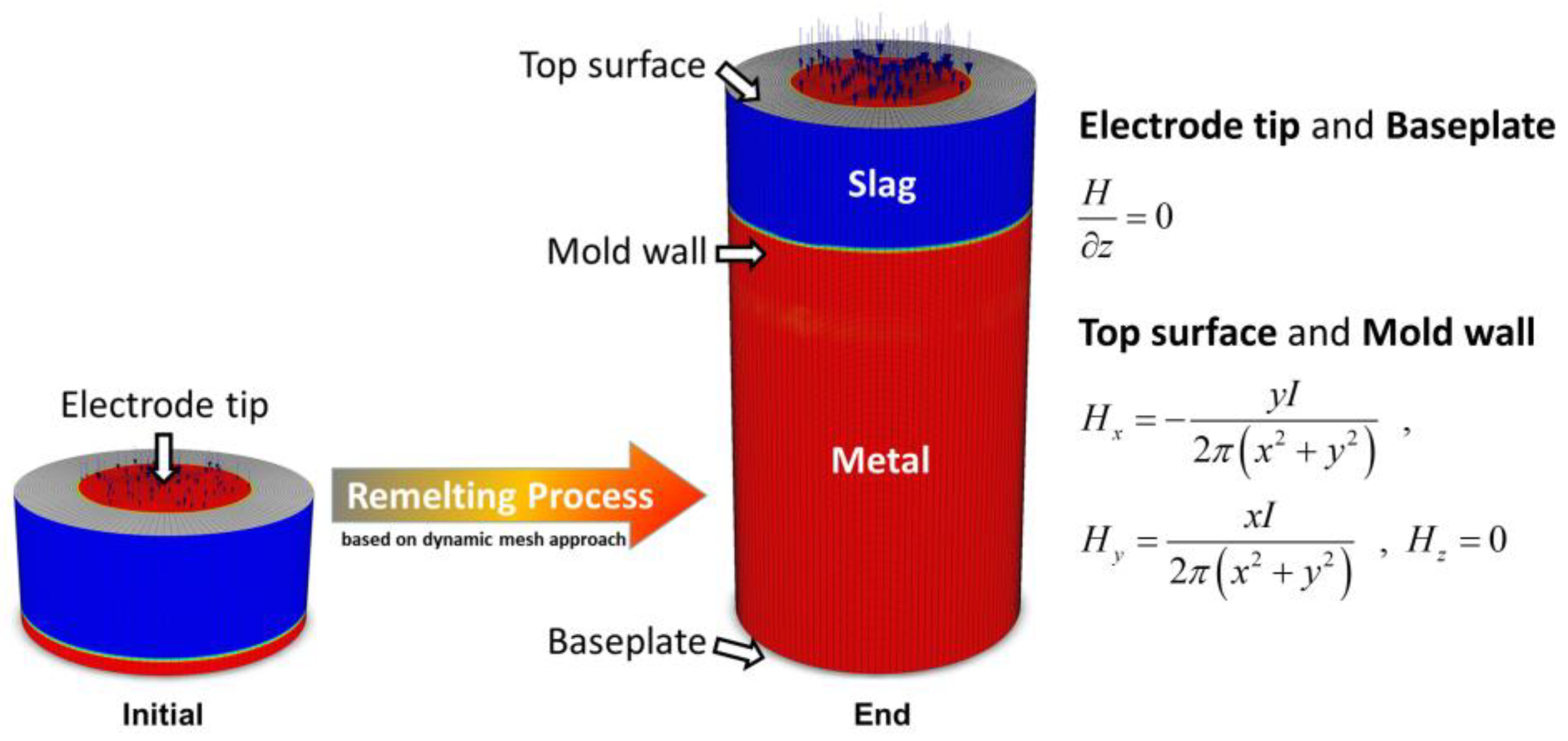
The mesh model with the required magnetic boundary conditions is displayed in Figure 2. The radial current was assumed to be zero at the electrode tip and baseplate, while a radial magnetic flux was imposed at the mold wall and top surface. Consequently, an alternating current is formed between the electrode tip and baseplate. Due to the insulation hypothesis between the mold and melt, no current was allowed to enter the mold [31]. The temperature at the electrode tip was superheated to 30 K over the liquidus of the electrode material. Since there were solidified slag skin and air gaps between the ingot and the mold, the thermal convection with equivalent heat transfer coefficients (400–800 W/m2·K) was applied at the mold wall and baseplate [32]. The rotation of electrode is achieved by imposing an angular velocity on the electrode tip. The top surface was set to be zero shear stress, while no-slip boundary was applied at the mold’s walls and bottom.
The governing equations were discretized by the commercial package ANSYS Fluent (Version 12.0, ANSYS Inc., Canonsburg, PA, USA), and the complicated phenomena were solved simultaneously. The in-house user-defined functions (UDF) were implemented, modeling considerations for electromagnetism, electrode melting rate, LST, and SDAS. The second-order upwind scheme was adopted. The 3D mesh used in the simulation initially consists of 3.09 × 10⁵ computational cells and grew to 1.30 × 10⁶ computational cells by the end. The growth of the ingot was considered by the dynamic layering method. The time step was 0.001 s with a minimum of 20 iterations and an associated convergence criteria (10−6) to ensure numerical accuracy. Therefore, each calculation case ran for 2200–2600 s of CPU time using parallel calculations on a multi-CPU cluster (24 cores, Intel Xeon Gold 5220R @ 2.20 GHz, Shenyang, Liaoning, China). Each transient case required about 20 days of wall-clock time.

4. Results and Discussions

4.1. Model Validation

Experiments using a 200-kg scale ESR furnace (Northeastern University, Liaoyang, Liaoning, China) with a static electrode were conducted under argon protection to validate the integrated model. The identical process parameters and materials were adopted both in the experiment and calculations. The constant power melting regime was employed. The whole ESR experiment, including the arcing and feeding stages, lasted about 2 h.
Due to the sealed reactor, it is difficult to measure the internal data of the high-temperature melts. According to Section 2.2, the electrode melting rate can characterize the combining effect of melt flow and heat transfer on the electrode and, thus, can be used to validate the model’s accuracy. This rate can be real-time estimated by the electrode position using the PLC programming in the experiment. Figure 3 plots the comparison of electrode melting rate between the measured and predicted results. As depicted, the fluctuation of melting rate is inevitable, due to the periodical formation and detachment of droplets. More instabilities in the experiment, such as the variation of electrode immersion depth, caused a much more noticeable fluctuation of the measured rate. The averaged values of the measured and predicted melting rates are 0.0231 and 0.0238 kg/s, respectively. This discrepancy is mainly attributed to uncertainties in the material properties and boundary conditions. The excellent agreement between both results ensures the reliability and accuracy of the model.
The averaged melting rates are 0.0238, 0.0247, 0.0276, and 0.0261 kg/s in the cases rotating at 0, 20, 40, and 60 rpm, respectively. Compared to the static one, the productivities are enhanced by 3.78%, 15.97%, and 9.66% at the rotating speeds of 20, 40, and 60 rpm, respectively. Obviously, the productivity reaches a maximum when the rotating speed is 40 rpm. This trend is influenced by the combination of slag temperature and effective thermal conductivity, which usually vary in opposite patterns [16]. Furthermore, a noticeable reduction in the amplitude of electrode melting rate is observed as the rotating speed increases. It indicates that the rotation of electrode could also improve the stability of ESR process.

4.2. Magnetohydrodynamic Flow

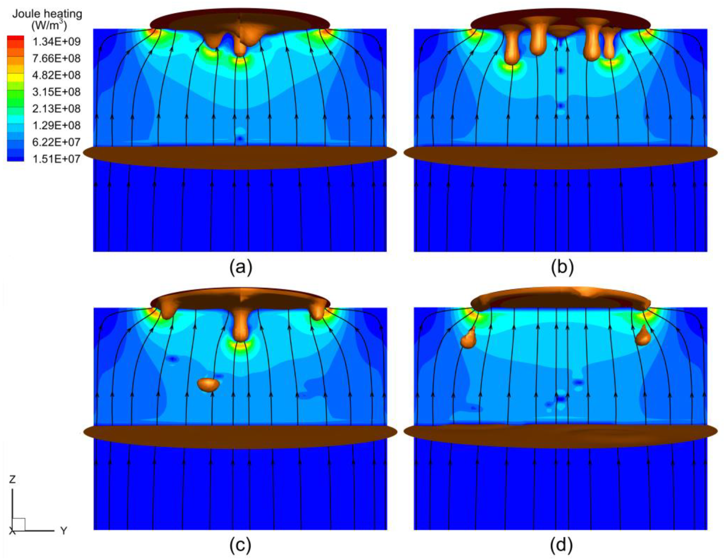
Figure 4 displays the predicted distributions of Joule heating density and current paths in the mold with different rotating speeds. The overwhelming majority of the Joule heating is generated in the slag pool. Due to the very high electrical conductivity difference between the slag and metal, the current tends to flow through the metal droplets. Consequently, higher Joule heating density was located at the slag underneath the periphery of the electrode and droplet tip. As the rotating speed increased, the region of high Joule heating density migrated outward, but the total amount of Joule heating remained almost the same. In the static condition, the Lorentz force, which is perpendicular to the direction of the current and points inward, promotes the inward convergence of molten metal at the electrode tip. However, the Lorentz force was countered by the centrifugal force in the opposite direction under rotation. As the rotating speed increased, the effect of the Lorentz force on the formation and dripping of droplets grew increasingly smaller.
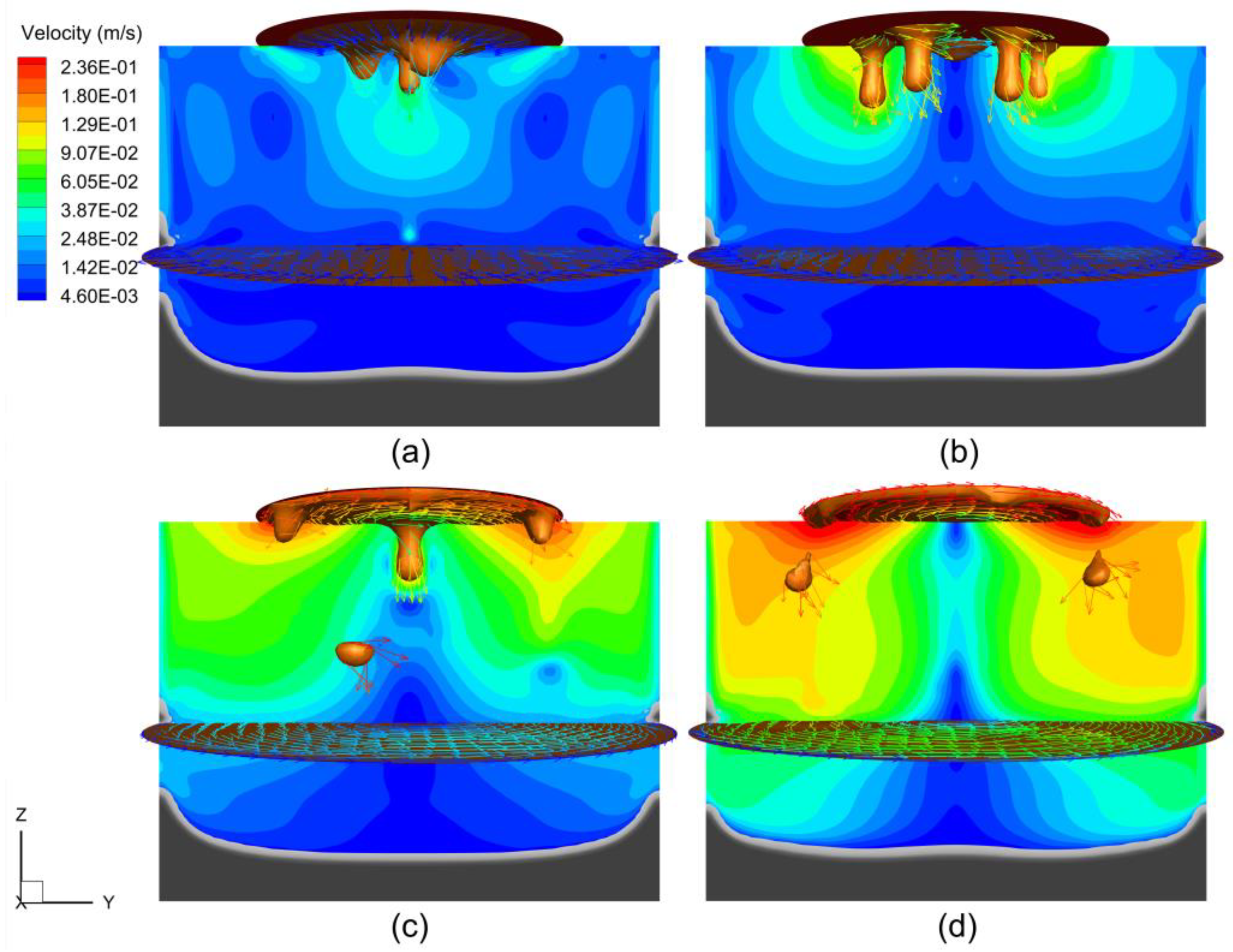
Figure 5 displays the predicted flow fields in the mold with different rotating speeds. In the static condition, the slag flows downward in the center under the action of falling droplets but flows upward at the outer sides. As the electrode rotates, the droplets detach at the periphery of electrode tip rather than at the center, resulting in a vortex direction reversed from that in the static condition. Most significantly, the electrode rotation drives the melt, creating an intense swirling flow in the slag layer and liquid metal pool, which weakens with decreasing altitude. The volume-averaged turbulent kinetic energy increased from 4.77 × 10⁻⁴ m−2·s−2 to 1.68 × 10⁻³ m−2·s−2 with the rise in rotating speed from 0 to 60 rpm, indicating that the rotation of the electrode enforces turbulence and, eventually, enhances heat convection in the melt.

4.3. Evolution of Metal Pool Profile

The predicted temperature distributions in the mold with different rotating speeds are shown in Figure 6. As depicted in Figure 6a, in the static case, the hotter region locates at the outer side of the upper slag layer. Joule heating is the only source for ESR systems. A lot of heat is carried away by the water-cooled mold, and a pronounced temperature gradient can be observed in the slag closest to the mold. Some heat is used to heat and melt the solid electrode, while the droplets carry some to the liquid metal pool. The high-temperature slag layer always covers the metal pool, and thus a liquid region, wherein the solidification has not occurred, is observed at the top of metal pool. The temperature decreased layer by layer from the top to bottom of the solidified ingot. At the beginning of the ESR process, the heat loss is primarily carried out through the baseplate. Thus, a U-shaped metal pool profile is formed. With the growth of the ingot, the cooling intensity of the baseplate becomes much weaker than that of the mold, resulting in a deeper V-shaped metal pool.
As the electrode rotated at 20 rpm, as shown in Figure 6b, the temperature of the lower part of the slag layer increased slightly. When the rotating speed increased to 40 rpm, as depicted in Figure 6c, the temperature distribution in the slag layer became more uniform. The flow structure with a rotating electrode enhances the thermal convection and diffusion from the outer side to the center of slag layer. When the rotating speed increased to 60 rpm, a significant reduction of slag temperature was observed (see Figure 6d). Consequently, the metal pool profile becomes flatter.
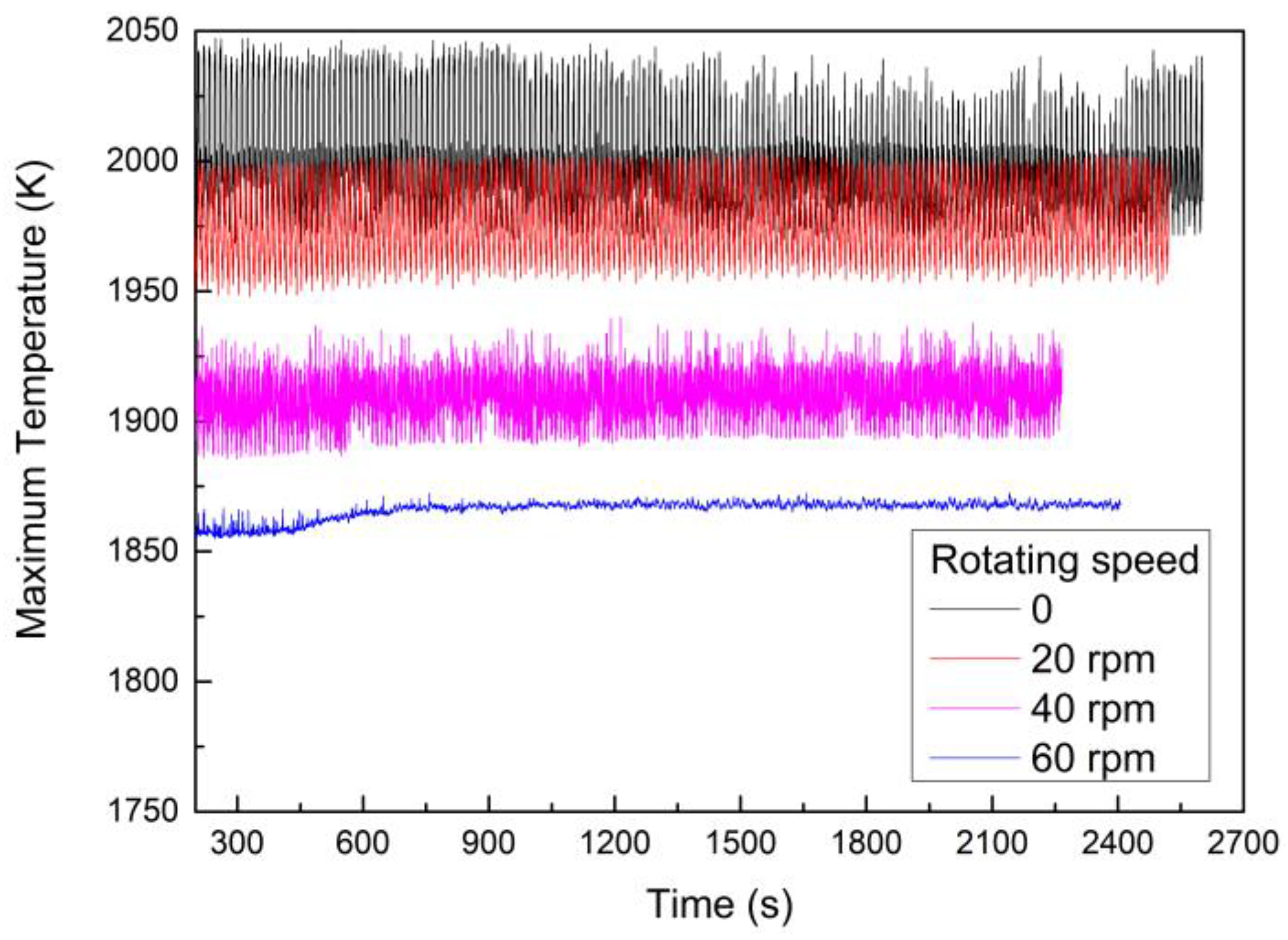
Figure 7 plots the time variation of the maximum temperature of the melt with different rotating speeds. The time-averaged values in the cases rotating at 0, 20, 40, and 60 rpm are 1999.0, 1977.8, 1910.0, and 1866.0 K, respectively. Without increasing the power input, more heat is used to melt the electrode or carried away by the cooling water as the electrode rotates. Thus, the maximum temperature is inversely proportional to the rotating speed of electrode. The standard deviation of maximum temperature decreases from 18.89 to 3.92, with the rotating speed rising from 0 to 60 rpm, meaning the thermal environment in the mold becomes more stable with increasing rotating speed.
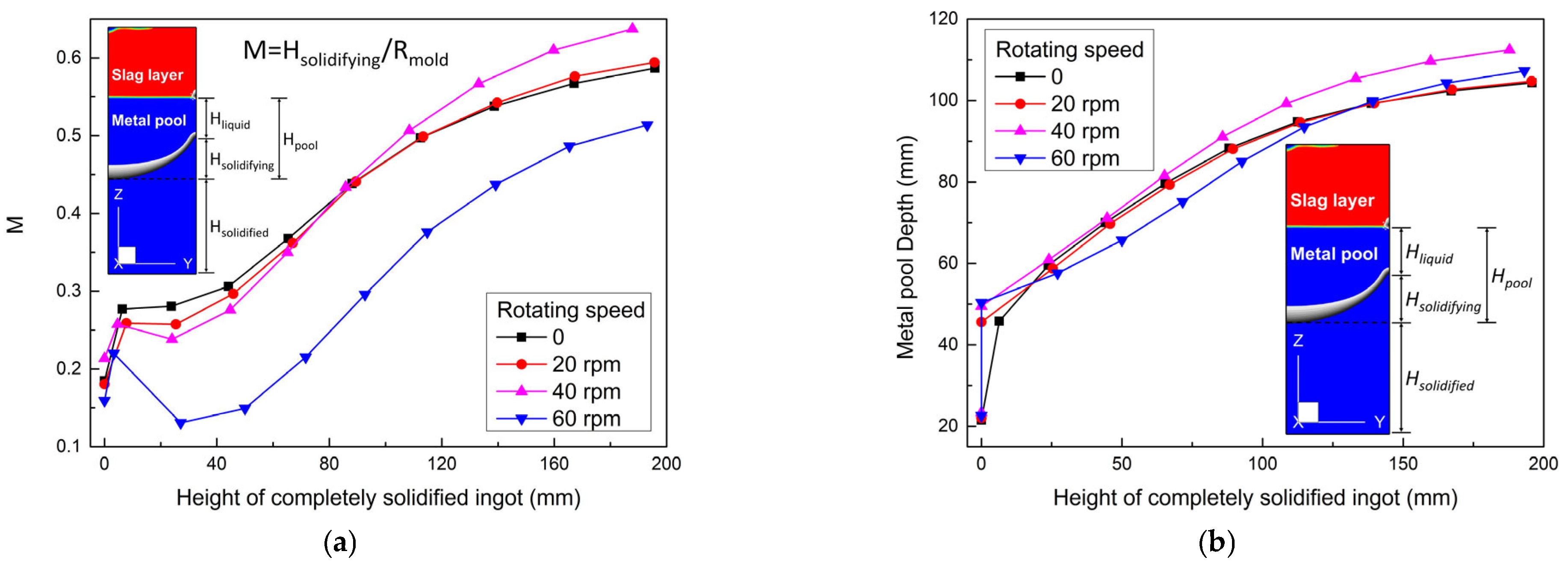
To evaluate the metal pool profile, the dimensionless number ‘M’ is introduced here, which expresses the ratio of the height of metal being solidified to the radius of the mold. As depicted in Figure 8a, the numbers exhibit an increasing trend with the growth of solidified ingot. At the end of the ESR process, the numbers tend to stabilize, which indicates a balanced state being reached between the heating and solidifying rates. In the early stage of the ESR process, the number decreases with the increasing rotating speed, that is, the metal pool profile is improved. However, the numbers eventually increase to 0.587, 0.594, 0.637, and 0.514, with the electrode rotating at 0, 20, 40, and 60 rpm, respectively. Compared with the static counterpart, the pool profiles are flattened by −1.19%, −8.52%, and 12.44% at the rotating speeds of 20, 40, and 60 rpm, respectively. The metal pool profile is improved remarkably only at 60 rpm.
Generally, an increase of slag temperature caused by varying process parameters (e.g., increasing the power input) means a faster melting rate, and consequently a deeper metal pool profile in a typical ESR process [8]. However, lower slag temperature and faster melting rates may co-occur as the rotating speed increases. Therefore, in the cases of an identical applied current, the effect of rotating speed on the metal pool profile depends on the competition between the melting rate and slag temperature. As the electrode rotates at a lower speed (i.e., 20 and 40 rpm), the melting rate plays a dominant role and contributes to a deepened metal pool profile. Especially at the rotating speed of 40 rpm, the melting rate far exceeds the solidifying rate, which leads to a pronounced increase of the metal pool depth (see Figure 8b). As the electrode rotates at a higher speed (i.e., 60 rpm), the slag temperature dominates the competition, and a flatter metal pool profile can be obtained.

4.4. Solidification Quality

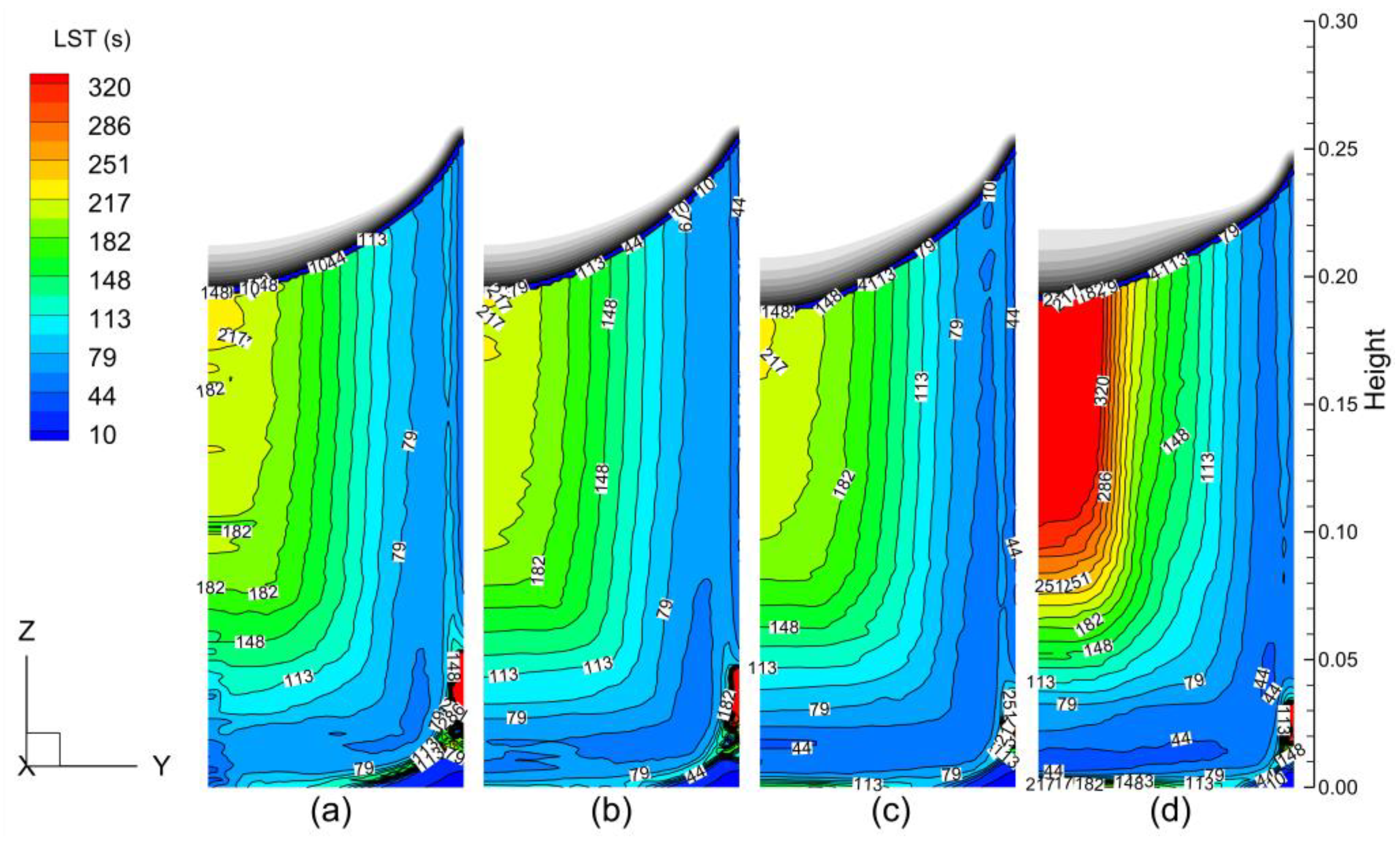
Figure 9 shows the predicted distributions of LST in the solidified ingot with different rotating speeds. As depicted, the LST increases layer by layer from the ingot surface close to the cooling boundary to the center far from the cooling boundary. The maximum LST always locates underneath the bottom of liquid metal pool in the stable remelting stage. With the increasing rotating speed, the LST at the outer side of the solidified ingot decreases. Yet, the LST at the center of ingot increased dramatically when the rotating speed increased to 60 rpm. This can be explained by the variation of the thickness of the mushy zone. The maximum thicknesses were 19.9, 17.4, 20.4, and 26.4 at the rotating speeds of 0, 20, 40, and 60 rpm, respectively. Therefore, it takes a longer time for metal to transition from the liquidus isotherm to the solidus isotherm at the rotating speed of 60 rpm.
As depicted in Figure 10, the SDAS in the solidified ingot exhibits a similar distribution with the LST due to the positive correlation between them (see Equation (21)). The maximum SDAS in the ingot center are 200.3, 198.8, 199.8, and 256.1 at the rotating speeds of 0, 20, 40, and 60 rpm, respectively. Compared to the static one, the SDAS is slightly improved at lower rotating speeds (i.e., 20 and 40 rpm) but is significantly worse at a higher rotating speed (i.e., 60 rpm). Figure 11 plots the predicted radial distribution of SDAS at different horizontal sections. It can be deduced that, in the cases of an identical applied current, the electrode rotation plays a positive role in improving the solidification quality of the outer side of ESR ingot. Still, the excessive rotating speed deteriorates the solidification quality of the center of ESR ingot. Therefore, the authors suggest that the increase of rotating speed should be accompanied by a reduction of power input to ensure a faster melting rate, a significant decrease in slag temperature, and, consequently, a quicker solidifying rate and a smaller SDAS.

5. Conclusions

A comprehensive transient model was developed to study the effect of electrode rotation on the evolution of metal pool profiles and the solidification quality of ESR ingots. The growth of an ESR ingot is predicted using the dynamic layering method.
  • The averaged melting rates were predicted as 0.0238, 0.0247, 0.0276, and 0.0261 kg/s in the cases of rotation at 0, 20, 40, and 60 rpm, respectively. Productivity reached a maximum of 15.97% at the rotating speed of 40 rpm, without increasing power.
  • As the electrode rotated, the droplets detached at the periphery of the electrode tip rather than at the center, resulting in a flow structure reversed from that in the static case. The electrode rotation drove the melt, creating a strong swirling flow in the slag layer and liquid metal pool, which weakened with decreasing altitude.
  • With rotating speeds ranging from 0 to 60 rpm, the maximum temperature of the melt decreased from 1999.0 to 1866.0 K. Meanwhile, the temperature distribution in the slag layer became more uniform, and the thermal environment more stable.
  • The metal pool profile was improved with increasing rotating speed in the early stage. At the end stage, compared with the static case, the pool profiles were flattened by −1.19%, −8.52%, and 12.44% at the rotating speeds of 20, 40, and 60 rpm, respectively. Only at a higher speed was the metal pool profile is improved, and remarkably. The effect of rotating speed on the metal pool profile depends on the competition between the melting rate and slag temperature.
  • The LST and SDAS increased layer by layer from the surface to the center of ESR ingot. Compared to the static case, the SDAS was slightly improved at lower rotating speeds (i.e., 20 and 40 rpm) but was significantly worse at a higher rotating speed (i.e., 60 rpm).
The authors believe that the increase of rotating speed accompanied by a reduction of power input is an effective way to simultaneously improve metal pool profiles and reduce LST and SDAS.

Author Contributions

Conceptualization, methodology, software, writing—original draft preparation, X.H.; writing—review and editing, supervision, Z.L. and B.L.; validation, data curation, Y.D. and F.W. All authors have read and agreed to the published version of the manuscript.

Funding

This research was funded by the National Natural Science Foundation of China (grant number 52104324 and 52171031) and Fundamental Research Funds for the Central Universities (No. N2025020).

Institutional Review Board Statement

Not applicable.

Informed Consent Statement

Not applicable.

Data Availability Statement

Not applicable.

Conflicts of Interest

The authors declare no conflict of interest.

References

  1. Kharicha, A.; Karimi-Sibaki, E.; Wu, M.; Ludwig, A.; Bohacek, J. Review on modeling and simulation of electroslag remelting. Steel Res. Int. 2018, 89, 1700100. [Google Scholar] [CrossRef]
  2. Hernandez-Morales, B.; Mitchell, A. Review of mathematical models of fluid flow, heat transfer, and mass transfer in electroslag remelting process. Ironmak. Steelmak. 1999, 26, 423–438. [Google Scholar] [CrossRef]
  3. Huang, X.C.; Li, B.K.; Liu, Z.Q. Three-dimensional mathematical model of oxygen transport behavior in electroslag remelting process. Metall. Mater. Trans. B 2018, 49, 709–722. [Google Scholar] [CrossRef]
  4. Huang, X.C.; Li, B.K.; Liu, Z.Q.; Li, X.L.; Sun, M.J. Numerical investigation and experimental validation of motion and distribution of nonmetallic inclusions in argon protection electroslag remelting process. Metals 2018, 8, 392. [Google Scholar] [CrossRef] [Green Version]
  5. Li, B.K.; Wang, Q.; Wang, F.; Chen, M.Q. A coupled cellular automaton-finite-element mathematical model for the multiscale phenomena of electroslag remelting H13 die steel ingot. JOM 2014, 66, 1153–1165. [Google Scholar] [CrossRef]
  6. Fezi, K.; Yanke, J.; Krane, M.J.M. Macrosegregation during electroslag remelting of alloy 625. Metall. Mater. Trans. B 2015, 46, 766–779. [Google Scholar] [CrossRef]
  7. Wang, Q.; Wang, F.; Li, B.K.; Tsukihashi, F. A three-dimensional comprehensive model for prediction of macrosegregation in electroslag remelting ingot. ISIJ Int. 2015, 55, 1010–1016. [Google Scholar] [CrossRef] [Green Version]
  8. Viswanathan, S.; Melgaard, D.K.; Patel, A.D.; Evans, D.G. Effect of processing parameters on temperature profiles, fluid flow, and pool shape in the ESR process. In Proceedings of the Liquid Metal Processing and Casting, Santa Fe, NM, USA, 18–21 September 2005. [Google Scholar]
  9. Patel, A.D.; Gierula, M.; Tallman, D.J. Bounds on model parameters for computational analysis of the ESR process. In Proceedings of the Liquid Metal Processing and Casting, Santa Fe, NM, USA, 20–23 September 2009. [Google Scholar]
  10. Wang, Q.; Yan, H.G.; Ren, N.; Li, B.K. Effect of slag thickness on macrosegregation and transition zone width of electroslag remelting dual alloy ingot. JOM 2016, 68, 397–400. [Google Scholar] [CrossRef]
  11. Chumanov, I.V.; Chumanov, V.I. Technology for electroslag remelting with rotating of the consumable electrode. Metallurgist 2001, 45, 125–128. [Google Scholar] [CrossRef]
  12. Schwenk, M.; Friedrich, B. Enhancing the electroslag remelting process: Development and implementation of a rotating electrode set-up. In Proceedings of the Liquid Metal Processing and Casting, Philadelphia, PA, USA, 10–13 September 2017. [Google Scholar]
  13. Chumanov, V.I.; Chumanov, I.V. Increasing the efficiency of the electroslag process and improving the metal quality by rotating a consumable electrode: Part 1. Russ. Metal. 2010, 6, 499–504. [Google Scholar] [CrossRef]
  14. Demirci, C.; Mellinghoff, B.; Schlüter, J.; Wissen, C.; Schwenk, M.; Friedrich, B. Results of the new generation ESR (electroslag remelting) unit with rotating electrode, designed by SMS Mevac GmBH. In Proceedings of the Liquid Metal Processing and Casting, Birmingham, UK, 8–11 September 2019. [Google Scholar]
  15. Deng, N.Y.; Shi, X.F.; Chen, J.S.; Chang, K.H.; Yu, W.C.; Wang, J.J.; Chang, L.Z. Numerical simulation of mold rotation and its effect on carbides in HSS ESR ingot. Chin. J. Eng. 2020, 42, 516–526. [Google Scholar]
  16. Huang, X.C.; Li, B.K.; Liu, Z.Q.; Li, M.Z.; Qi, F.S. Modeling of fluid flow, heat transfer and inclusion removal in electroslag remelting process with a rotating electrode. Int. J. Heat Mass Tran. 2020, 163, 120473. [Google Scholar] [CrossRef]
  17. Hirt, C.W.; Nichols, B.D. Volume of fluid (VOF) method for the dynamics of free boundaries. J. Comput. Phys. 1981, 39, 201–225. [Google Scholar] [CrossRef]
  18. Wang, Q.; He, Z.; Li, G.Q.; Li, B.K.; Zhu, C.Y.; Chen, P.J. Numerical investigation of desulfurization behavior in electroslag remelting process. Int. J. Heat Mass Tran. 2017, 104, 943–951. [Google Scholar] [CrossRef]
  19. Jardy, A.; Ablitzer, D.; Wadier, J.F. Magnetohydrodynamic and thermal behavior of electroslag remelting slags. Metall. Trans. B 1991, 22, 111–120. [Google Scholar] [CrossRef]
  20. Liu, Z.Q.; Niu, R.; Wu, Y.D.; Li, B.K.; Gan, Y.; Wu, M.H. Physical and numerical simulation of mixed columnar-equiaxed solidification during cold strip feeding in continuous casting. Int. J. Heat Mass Tran. 2021, 173, 121237. [Google Scholar] [CrossRef]
  21. Li, X.L.; Li, B.K.; Liu, Z.Q.; Niu, R.; Huang, X.C. Large eddy simulation of electromagnetic three-phase flow in a round bloom considering solidified shell. Steel Res. Int. 2019, 89, 1800133. [Google Scholar] [CrossRef]
  22. Kharicha, A.; Schützenhöfer, W.; Ludwig, A.; Tanzer, R.; Wu, M. On the importance of electric currents flowing directly into the mould during an ESR process. Steel Res. Int. 2008, 79, 632–636. [Google Scholar] [CrossRef]
  23. Karimi-Sibaki, E.; Kharicha, A.; Bohacek, J.; Wu, M.; Ludwig, A. A dynamic mesh-based approach to model melting and shape of an ESR electrode. Metall. Mater. Trans. B 2015, 46, 2049–2061. [Google Scholar] [CrossRef]
  24. Yanke, J.; Krane, M.J.M. A parametric study of slag skin formation in electroslag remelting. In Proceedings of the Liquid Metal Processing and Casting, Austin, TX, USA, 22–25 September 2013. [Google Scholar]
  25. Kharicha, A.; Ludwig, A.; Wu, M. 3D simulation of the melting during an electro-slag remelting process. In Proceedings of the TMS 2011 Annual meeting & Exhibition, San Diego, CA, USA, 27 February–3 March 2011. [Google Scholar]
  26. Yanke, J.; Fezi, K.; Trice, R.W.; Krane, M.J.M. Simulation of slag-skin formation in electroslag remelting using a volume of fluid method. Numer. Heat Trans. A Appl. 2015, 67, 268–292. [Google Scholar] [CrossRef]
  27. Ballantyne, A.S.; Kennedy, R.J.; Mitchell, A. The influence of melting rate on structure in VAR and ESR ingots. In Proceedings of the 5th International Conference on Vacuum Metallurgy and Electroslag Remelting Processes, Munich, Germany, 11–15 October 1976. [Google Scholar]
  28. Flemings, M.C. Solidification Processing; McGraw-Hill Book Co.: New York, NY, USA, 1974; p. 148. [Google Scholar]
  29. Choudhary, M.; Szekely, J. The effect of temperature dependent electrical conductivity on flow and temperature fields in slags in ESR systems. Metall. Trans. B 1981, 12, 418–421. [Google Scholar] [CrossRef]
  30. Liu, Y.; Zhang, Z.; Li, G.Q.; Wu, Y.; Xu, D.M.; Li, B.K. Investigation of fluoride vaporization from CaF2-CaO-Al2O3 slag for vacuum electroslag remelting. Vacuum 2018, 158, 6–13. [Google Scholar] [CrossRef]
  31. Weber, V.; Jardy, A.; Dussoubs, B.; Ablitzer, D.; Ryberon, S.; Schmitt, V.; Hans, S.; Poisson, H. A comprehensive model of the electroslag remelting process: Description and validation. Metall. Mater. Trans. B 2009, 40, 271–280. [Google Scholar] [CrossRef]
  32. Dilawari, A.H.; Szekely, J. Heat transfer and fluid flow phenomena in electroslag refining. Metall. Trans. B 1978, 9, 77–87. [Google Scholar] [CrossRef]
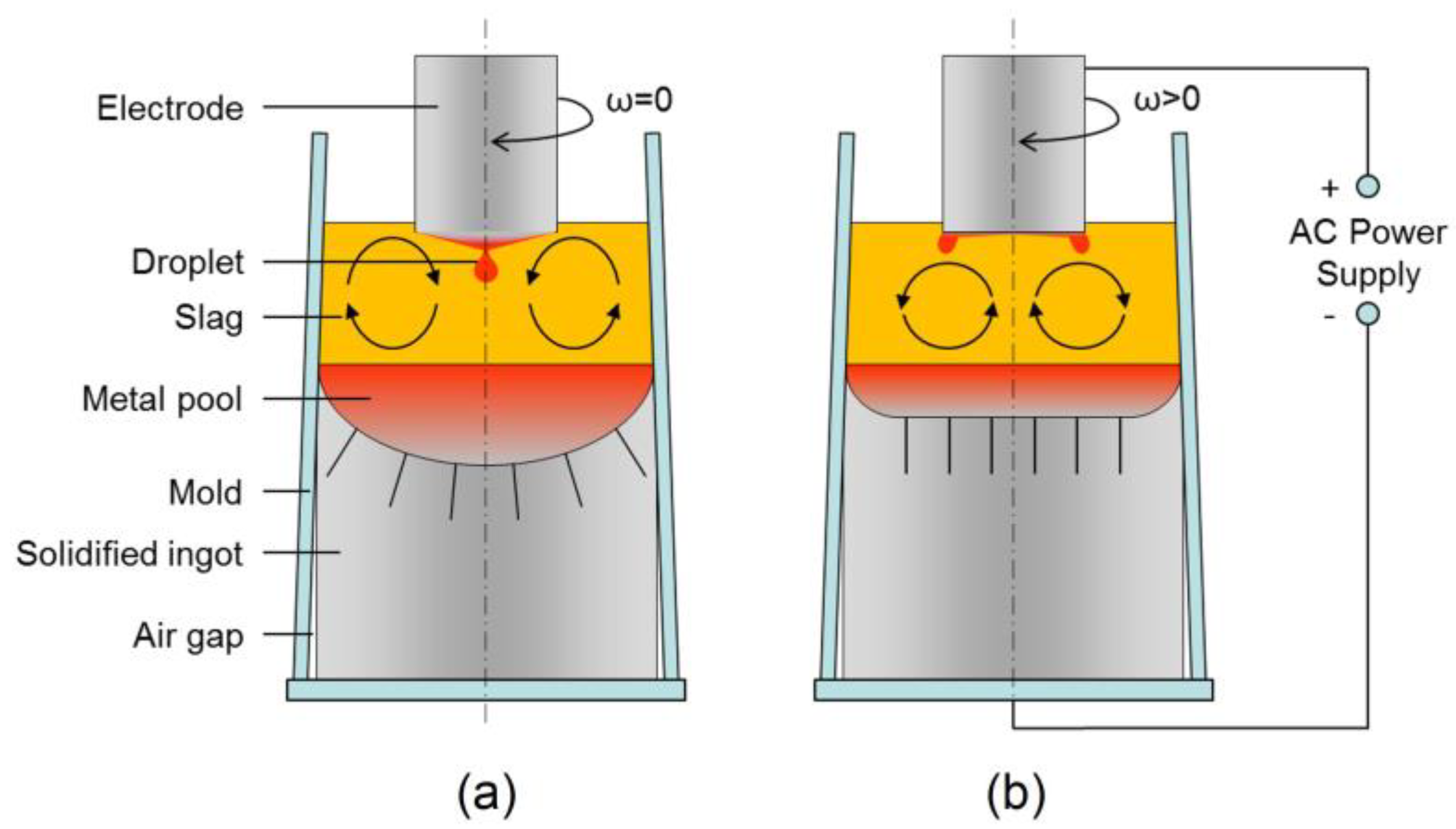
Figure 1. Process schematics of general ESR (a) and ESR with a rotating electrode (b) [16].
Metals 11 01675 g001
Figure 2. Mesh model with required magnetic boundary conditions.
Metals 11 01675 g002
Figure 3. Comparison of electrode melting rates between the experimental and calculated results.
Metals 11 01675 g003
Figure 4. Predicted distributions of Joule heating density and current paths in the mold with the electrode rotating at different speeds: (a) 0; (b) 20 rpm; (c) 40 rpm; (d) 60 rpm. The current mesh height is 150 mm.
Metals 11 01675 g004
Figure 5. Predicted flow fields in the mold with the electrode rotating at different speeds: (a) 0; (b) 20 rpm; (c) 40 rpm; (d) 60 rpm. The current mesh height is 150 mm.
Metals 11 01675 g005
Figure 6. Predicted temperature distributions in the mold with the electrode rotating at different speeds: (a) 0; (b) 20 rpm; (c) 40 rpm; (d) 60 rpm.
Metals 11 01675 g006
Figure 7. Time variation of maximum temperature of the melt with the electrode rotating at different speeds.
Metals 11 01675 g007
Figure 8. Evolution of metal pool profile with the electrode rotating at different speeds: (a) M; (b) metal pool depth.
Metals 11 01675 g008
Figure 9. Predicted distributions of LST in the solidified ingot with the electrode rotating at different speeds: (a) 0; (b) 20 rpm; (c) 40 rpm; (d) 60 rpm.
Metals 11 01675 g009
Figure 10. Predicted distributions of SDAS in the solidified ingot with the electrode rotating at different speeds: (a) 0; (b) 20 rpm; (c) 40 rpm; (d) 60 rpm.
Metals 11 01675 g010
Figure 11. Predicted radial distribution of SDAS at different horizontal sections: (a) Z = 0.18 m; (b) Z = 0.05 m.
Metals 11 01675 g011
Table 1. Governing equations in this model [16].
Governing EquationsSymbols
(1) VOF approach
α t + ( v α ) = 0 (1)
ϕ ¯ = ϕ m α m + ϕ s ( 1 α m ) (2)
magnetic flux density ( B )
specific heat ( c p )
primary dendrite arm spacing ( d 1 )
buoyancy force ( F b )
Lorentz force ( F e )
surface tension ( F s t )
damping force ( F d a m p )
liquid fraction ( f l )
gravitational acceleration ( g )
magnetic field intensity ( H )
complex amplitude ( H )
enthalpy ( H )
sensible enthalpy ( h )
current density ( J )
effective thermal conductivity ( k e f f )
latent heat of fusion ( L )
normal vector ( n )
pressure ( p )
Joule heating ( Q J )
temperature ( T )
reference temperature( T r e f )
time ( t )
velocity ( v )
volume fraction ( α )
thermal expansion coefficient ( β )
property ( ϕ )
electrical conductivity ( σ )
density ( ρ )
magnetic diffusivity ( η )
effective viscosity ( μ e f f )
turbulent viscosity ( μ t )
surface tension coefficient ( σ i j )
curvature ( κ )
(2) fluid flow
ρ t + ( ρ v ) = 0 (3)
( ρ v ) t + ( ρ v v ) = p + μ e f f 2 v + F e + F b + F s t + F d a m p (4)
F e = J × B (5)
F b = ρ g β ( T T r e f ) (6)
F s t = σ i j 2 ρ κ α ρ i + ρ j n (7)
F d a m p = ( 1 f l ) f l 3 180 μ d 1 2 v (8)
(3) heat transfer and solidification
t ( ρ H ) + ( v ρ H ) = ( k e f f T ) + Q J (9)
H = h + f l L (10)
h = h r e f + T r e f T c p d T (11)
Q J = J J σ (12)
(4) electromagnetic field
H = H e j w t   with   j 2 = 1 (13)
H t = η 2 H (14)
Table 2. Physical properties and process parameters.
Physical PropertiesMetalSlag
density, kg·m−378502600
viscosity, Pa·s0.00441–6.3840.0175–0.0768
specific heat, J·kg−1·K−17521255
thermal conductivity, W·m−1·K−130.5210.5
electric conductivity, Ω−1·m−17.14 × 10⁵ ln σ = 6769 / T + 8.818
liquidus/solidus temperature, K1730/1636-
latent heat of fusion, kJ·kg−1270-
thermal expansion coefficient, K−12 × 10−41 × 10−4
Process parametersValue
electrode radius, mm60
mold radius, mm100
slag weight, kg6.5
current, kA3.2
frequency, Hz50
rotating speed of electrode, rpm0/20/40/60
Publisher’s Note: MDPI stays neutral with regard to jurisdictional claims in published maps and institutional affiliations.