Abstract
A TNM alloy ingot was fabricated with powder hot isostatic pressing (P-HIP) and short-time exposure treatment conducted at 750–1050 °C for 2–5 h. The tensile mechanical properties were investigated at room temperature and 800 °C. The results revealed that a fully lamellar microstructure of P-HIPed TNM alloy with only 0.3 vol.% β0 phase could be obtained by hot isostatic pressing at 1260 °C, under the pressure of 170 MPa, held for 4 h. When the exposure temperature was below 850 °C, the α2 lamellae were transformed into nano-scaled (α2 + γ) lamellae (i.e., the α2→α2 + γ transformation). With increases in the exposure temperature, the β0 phase began to precipitate within the α2 lamellae (α2→β0 transformation) at 950 °C. The α2→γ and the α2→β0 transformation both happened at 950–1050 °C, and the higher exposure temperature accelerated the diffusion of Mo and facilitated the α2→β0 transformation. The yield strength and elongation at RT and 800 °C were both improved after short-time high-temperature exposure treatment. The uniform distribution and nano-scaled interfacial β0 phase provided precipitation strengthening and were not harmful to the elongation.
1. Introduction
The TNM alloys, nominal chemical composition Ti-(42–45)Al-(3–5)Nb-(0.1–2)Mo-(0.1–0.2)B (in at.% percent), are considered to be attractive options for producing light high-temperature structural materials due to their low density, high modulus of elasticity, high creep resistance and oxidation resistance at elevated temperatures [1,2]. At room temperature (RT), the alloys mainly consist of three ordered structural phases, i.e., α2 phase (D019 structure), γ phase (L10 structure), and β0 phase (B2 structure) [3]. Furthermore, the fully lamellar microstructure with a balance of mechanical properties is more suitable for high-temperature structures [4,5]. Tailoring a fully lamellar microstructure and good thermal stability of the microstructure at elevated temperatures are significant concerns to extend the service temperature of TNM alloys for aero-engine applications.
The fabrication of TNM alloy ingots by vacuum arc remelting (VAR) is treated as a cost-effective process. However, the large differences in melting points and densities of the constituting elements lead to chemical heterogeneities and cast defects inherited from solidification [6,7]. Furthermore, the disordered β phase with ductile properties in the TNM alloy is attributed to thermal formability [8]. A large amount of blocky ordered β0 phase is retained at RT and located at the colony boundaries or triple junctions. It is not only difficult to obtain a fully lamellar microstructure but also results in a deterioration of the tensile mechanical properties [9,10]. Many approaches have been applied to eliminate the ordered β0 phase to achieve a fully lamellar structure through different processes. The volume fraction of the β0 phase in cast/HIP TNM alloy effectively decreases from 14% to 3% through multi-step heat treatment [11]. Additionally, the volume fraction of the β0 phase in a forged TNM alloy could be further reduced to approximately 2% if treated at 1270 °C for 1 h, followed by an oil quench. The non-equilibrium microstructure conditions followed by a stabilizing temperature resulted in cellular reaction; the blocky β0 was re-precipitated at the colony boundary and caused the deterioration of the fully lamellar structure as well as a reduction in tensile strength [12]. Powder metallurgy is a very attractive processing route for TiAl structure components since a high degree of chemical homogeneity can be achieved while avoiding segregation [13]. TNM ingots with near-γ grain microstructures have been fabricated by the P-HIP method. A near-lamellar microstructure was obtained by heat treatment, and the volume fraction of the β0 phase was reduced from 14% to 3% [14]. It provides the possibility for HIP fabrication to tailor different microstructure types, and there are few reports on TNM alloys fabricated by this method. Consequently, it is necessary to investigate the influence of P-HIP parameters on the microstructure.
Thermal stability refers to the maintenance of sufficient microstructure stability to retain adequate strength during high-temperature exposure or thermo-mechanical coupling conditions [15]. Microstructural instability of TiAl alloys after long-term exposure at high temperatures restricts their application. These alloys present microstructural degradation, such as lamellar structure degradation, globular γ precipitation, and phase transformations such as α2→β0, (α2 + γ) lamellae→β0 + γ [16,17,18]. According to the reports by Huang et al. [19,20,21], TiAl alloys with added β stabilizer elements (such as Nb, Hf, and W, etc.) were indicated to have good thermal stability during long-term exposure treatment. This approach could restrict the parallel decomposition of α2 lamellae into ultrafine γ lamellae. However, the volume fraction of the β0 phase after exposure treatment increased to over 7% and the ω phase precipitated within the β0 phase. These led to deterioration of the ductility and fatigue properties [22]. Kastenhuber M. et al. [23] found that the microstructure of an as-forged TNM alloy treated at 900–1150 °C for 3–30 h presented a varying degree of discontinuous precipitation (DP) at colony boundaries, i.e., (α2 + γ) lamellae→β0 + γ. With increases in temperature and time, the degradation of the lamellar structure became worse. The characteristics of microstructural instability at the initial stage under high temperatures are still unclear. Therefore, it is worth investigating microstructural instability at the initial stage after high-temperature exposure treatments, and its influence on tensile performance.
In this study, TNM ingots were fabricated via the P-HIP method. Microstructure stability was analyzed at high temperatures for short-time exposure treatment. The microstructure characteristics were systematically investigated. Furthermore, the tensile properties were examined at room temperature and 800 °C.
2. Materials and Methods
The pre-alloy TNM powder was fabricated using the plasma rotation electron powder (PREP) method, and the average particle size was 90.802 μm as measured with a Mastersizer 2000 Instrument (Malvern Panalytical Ltd., Malvern, UK). The powder was sealed in a pure titanium can with dimensions of 40 mm diameter and 280 mm height, and then hot isostatically pressed at 1260 °C under a pressure of 170 MPa and held for 4 h. The actual chemical compositions of the P-HIPed TNM ingots are displayed in Table 1. For evaluating the stability of the microstructure, cylindrical samples with a diameter of 10 mm and a height of 10 mm were cut from the ingot and used for different heat treatments, i.e., isothermal holding at 750–1050 °C for 2–5 h followed by furnace cooling. The heat-treated cylindrical samples cut along the central axis were used for microstructure characterization after standard metallographic polishing procedures. The microstructures were characterized using back-scattered electron (BSE) mode on a FEI Helios G4 CX scanning electron microscope (SEM) (Thermo Fisher Scientific Inc., Waltham, MA, USA). Statistical data were extracted from 5–10 SEM images using Image-Pro Plus software (Media Cybernetics Inc., Las Vegas, CA, USA). High-angle annular dark-field (HAADF-STEM) and energy-dispersed X-ray spectroscopy (EDX) results were obtained using an FEI Talos F200X transmission electron microscope (TEM) (Thermo Fisher Scientific Inc., Waltham, MA, USA) operated at 200 kV. EDX results are presented as arithmetic mean values from five locations. Thin foils for TEM observation were prepared by twin-jet electron polishing using a solution of 500 mL electrolyte (5% perchloric, 35% butanol, 65% methanol) at −35 °C and 30 V. Tensile test samples with a diameter of 5 mm and a gauge length of 25 mm were cut along the length of the ingot. The tensile tests were conducted on an Instron universal test machine (Instron Inc., Norwood, MA, USA) at temperatures of 25 °C and 800 °C under a crosshead speed of 0.15 mm/min. The mechanical properties were obtained as arithmetic mean values from two tensile test sample measurements.

Table 1.
The chemical composition of the P-HIPed TNM ingot (at. %).
3. Results and Discussion
3.1. The Initial Microstructure
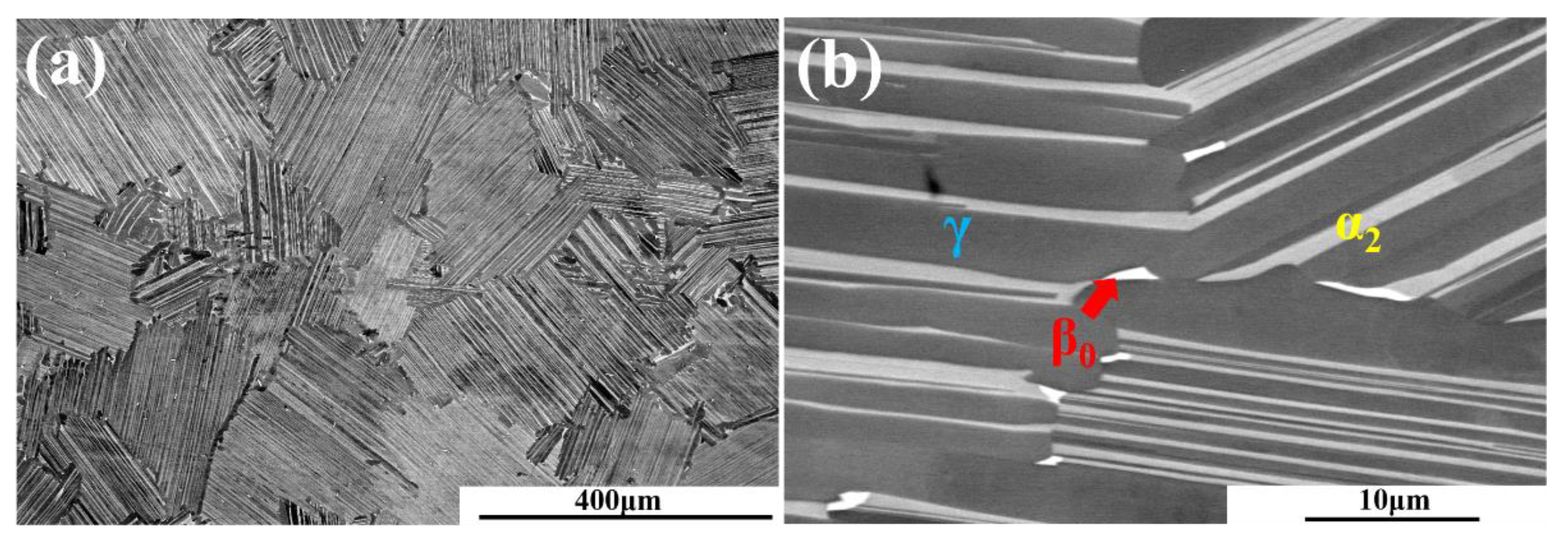
Figure 1 shows the BSE micrographs of the P-HIPed TNM alloy at different magnifications. It can be observed from Figure 1a that the microstructure exhibited a fully lamellar (α2 + γ) structure with an average colony size of about 153 ± 21 μm. Since the HIP temperature was close to the resolved Tγ (T = 1260 °C), the α phase grew without obstacles of β or γ phases. A high-magnification micrograph is shown in Figure 1b, from which can be observed that only a very small amount of β0 particles were located at the colony boundaries. The volume fractions of γ, α2, and β0 phase were 72.1 ± 1.7%, 27.6 ± 1.4%, and 0.3 ± 0.1%, respectively. It should be mentioned that the current microstructure was very different from reported as-cast microstructures of TNM alloys where the (α2 ± γ) lamellar colonies are surrounded by obvious β0 phase and globular γ-grains. The volume fraction of β0 phase in these casted TNM alloys is about 3–5 vol.% [11,24]. The significant reduction in the β0 phase in the microstructure of the P-HIPed TNM alloy can be considered to result from the following four aspects. (Ⅰ) As the Pre-alloy TNM powder was fabricated by the PREP method with a cooling rate of approximately 105–106 K/s [25], there was almost no segregation comparable to that produced by ingot metallurgy in Pre-alloy TNM powders. (Ⅱ) Since the closed packed structures of α2 and γ were higher than that of the β phase, the unstable β phase tended to transform α2 or γ phase under higher compression stress at high temperatures [26]. During the HIP process, the α→γ phase transformation path was dominant, and the β phase therefore transformed into γ or α2 phase [27]. (Ⅲ) The HIP process was conducted at 1260 °C, where the volume fraction of the β/β0 phase was at a minimum, which is equivalent to a heat treatment to reduce the β phase [11]. (Ⅳ) The higher oxygen content can be credited with stabilizing the lamellar microstructure and transferring the phase transformation path from α→γ to α→α2 + γ [28]. Consequently, a fully lamellar TNM alloy microstructure with a lower percentage of β0 phase could be obtained by the P-HIP method.

Figure 1.
SEM-BSE micrographs of the microstructure of the P-HIPed TNM alloy. (a) Low-magnification micrograph showing the fully lamellar microstructure; (b) high-magnification micrograph showing the β0 particles distributed at colony boundaries.
3.2. Microstructure Characteristics after Exposure Treatment
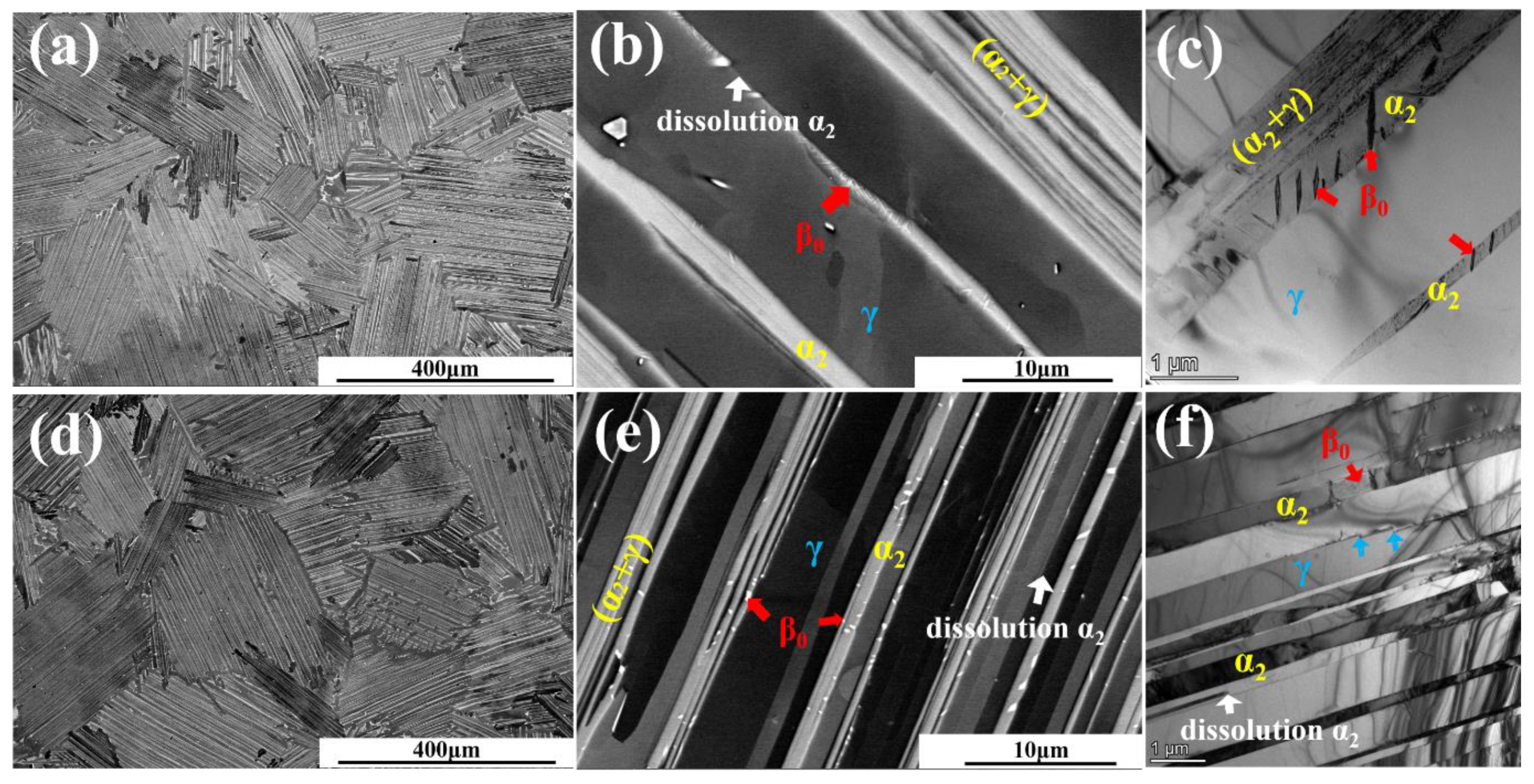
Figure 2 shows the microstructure morphology after exposure treatment at 750–850 °C for 5 h. According to the low-magnification SEM-BSE micrographs displayed in Figure 2a,d,g, the microstructures still exhibited fully lamellar (α2 + γ) structures and the average colony sizes were 154 ± 18 μm, 155 ± 25 μm, and 158 ± 27 μm, respectively. No significant differences from the P-HIPed microstructure were observed. To check if subtle structural changes existed, high-magnification SEM-BSE micrographs and TEM bright-filed images of the hot-exposed microstructures are presented in Figure 2b,c,e,f,h,i. It can be clearly seen that the lamellae remained long and straight without being disturbed by precipitates, and that small numbers of β0 particles were still located at colony boundaries. A noticeable feature is that bunches of nano-scaled (α2 + γ) lamellae in Figure 2 began to appear when the exposure temperature was 750 °C and increased in number with increases in the exposure temperature. These bunches of nano-scaled (α2 + γ) lamellae resulted from the dissolution of the coarse α2 lamellae, i.e., α2→α2 + γ, leading to thickening of the γ lamellae, as seen in Figure 2f,i.
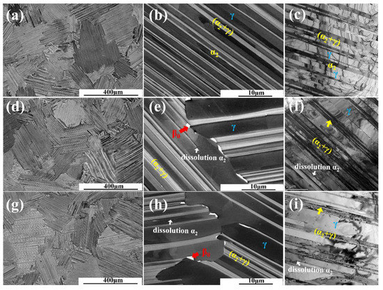
Figure 2.
Microstructures of P-HIPed TNM alloys after different exposure treatments: (a–c) 750 °C/5 h/FC; (d–f) 800 °C/5 h/FC; (g–i) 850 °C/5 h/FC.
Figure 3 shows the characterization of the microstructures after exposure treatment at 950 °C and 1050 °C for 2 h. It can be seen that the exposed microstructures in mesoscale still exhibited fully lamellar (α2 + γ) structures (Figure 3a,d) showing no significant difference from the P-HIPed microstructure. The high-magnification SEM-BSE micrographs and TEM micrographs focusing on α2/γ lamellar structures are displayed in Figure 3b,d–f respectively. It can be observed that besides the finer nano-scaled (α2 + γ) lamellae which appeared in microstructures exposed at 750–850 °C (Figure 2), some nano-scaled β0 phase could be observed in the α2 lamellae (Figure 3b,d–f). This means that both the dissolution of the coarse α2 lamellae into (α2 + γ) lamellae and the phase transformation of α2→β0 could also be progressed when exposed at 950–1050 °C. Furthermore, the β0 phase at the lamellar interface increased in both size and proportion (Figure 4e,f) with the increase in the exposure temperature from 950 °C to 1050 °C.
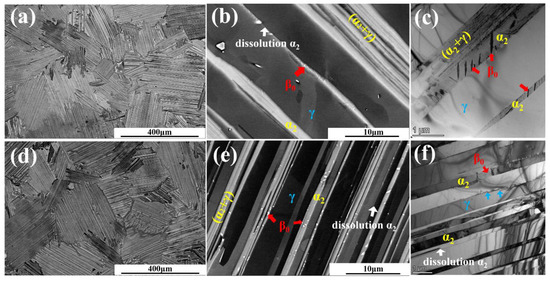
Figure 3.
Microstructures of P-HIPed TNM alloys after different exposure treatments. (a–c) 950 °C/2 h/FC; (d–f) 1050 °C/2 h/FC.
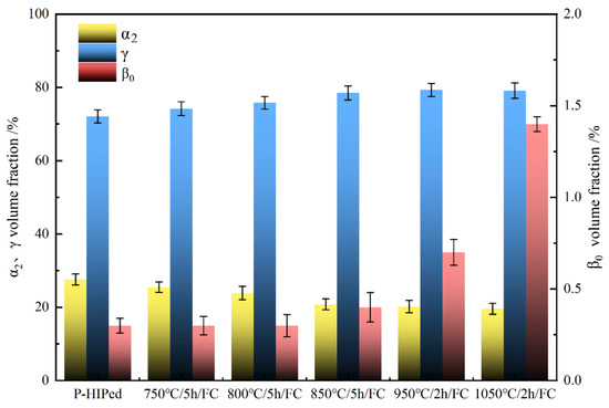
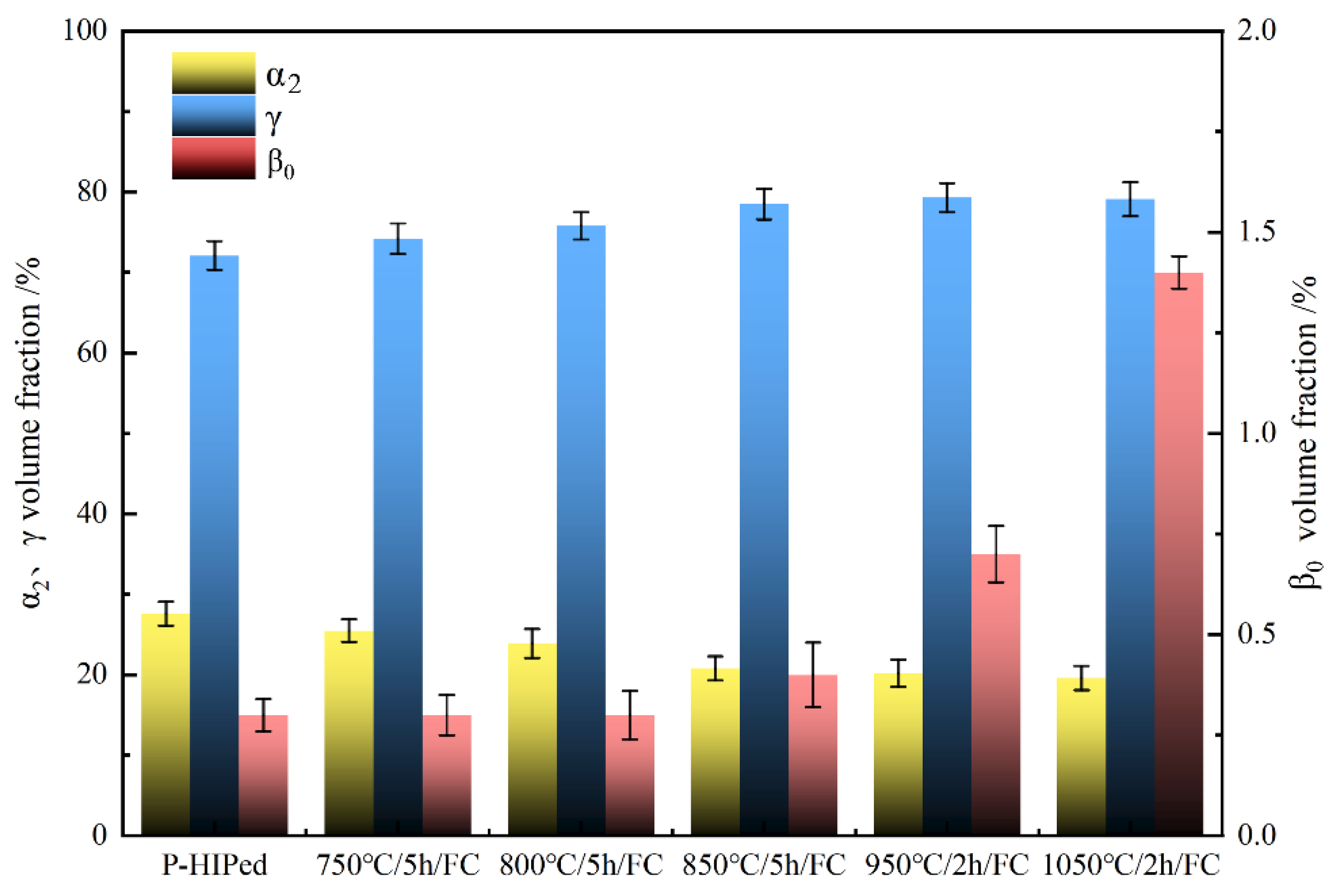
Figure 4.
The volume fractions of phases after different exposure treatments.
Figure 4 shows the phase proportion of TNM alloys after different treatments, in which the volume fraction of α2 and γ phases is relative to the left axis, and the volume fraction of β0 phase is relative to the right axis. The volume fractions of the γ, α2, and β0 phases were 72.1%, 27.6%, and 0.3% in the P-HIPed TNM sample, respectively. With increases in the exposure temperature, the volume fraction of the γ phase slightly increased while that of the α2 phase decreased. When the exposure temperature was below 850 °C, the phase transformation was dominated by α2→α2 + γ, and the proportion of β0 phase increased only to 0.5%. Correspondingly, the volume fractions of the γ and β0 phases were 79.3% and 0.7% in the sample exposed at 950 °C, and 79.1% and 1.4% in the sample exposed at 1050 °C. The α2→α2 + γ and the α2→β0 transformations both happened.
The β0 phase precipitated within the α2 lamellae in the P-HIPed TNM alloy after exposure at 1050 °C for 2 h is further represented within the STEM-HADDF image in Figure 5a. It can be observed that β0 precipitates nucleated at the α2/γ lamellar interfaces and grew into the α2 lamellae, as noted by the red arrows in Figure 5a. As the α2 lamellae had a higher solubility for Mo than the γ lamellae [29], based on the chemical composition of different phases listed in Table 2, the strong β-stabilizer Mo was expelled to the γ/α2 interfaces during the process of the dissolution of α2→γ, which promoted the nucleation of β0 phase at these interfaces [29,30]. The corresponding SAED pattern is displayed in Figure 5b. It is no wonder that the α2, γ, and β0 phases obeyed the orientation relationships <110>γ//<1120>α2//<111>β0 and {1–11}γ//{0001}α2//{1–10}β0. To figure out the interface feature in detail, the HRTEM image of the area marked with red circle in Figure 5a is displayed in Figure 5c. The atomic arrangements of different domains were marked as different phases and confirmed by their respective FFT images. It can be noticed that the segment of the β0/γ interface was decorated with some micro-ledges, but the segment of the α2/γ interface was relatively straight, as shown by the yellow dashed line in Figure 5c. It is well known that micro-ledges are the typical features of α2→γ transformation [30]. These kinds of ‘step-terrace’ configured interface micro-ledges can serve as heterogeneous nuclei for the β0 phase; thus, the β0/γ interface will replace the original α2/γ interface and exhibit the ‘step-terrace’ feature. Once the β0 phase is formed and occupies the micro-ledges, α2→γ transformation, characterized as the ledge-controlled mechanism, cannot be progressed. Furthermore, the segment of the straight α2/γ interface without micro-ledges can neither be the nucleus for the β0 phase nor trigger the α2→γ transformation.
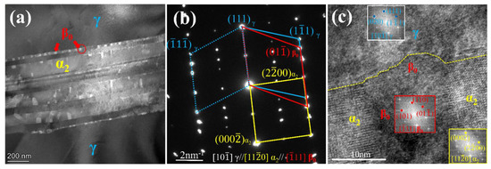
Figure 5.
(a) STEM-HADDF image showing α2 lamellae with β0 particles precipitated in a P-HIPed TNM alloy after 1050 °C/2 h/FC; (b) the SAED pattern; (c) HRTEM image of α2/β0/γ interface marked with the red circle in (a) and the corresponding FFT images.
Table 2.
TEM-EDX results showing the chemical composition of the β0, α2, and γ phases of TNM alloy after 1050 °C/2 h/FC (at.%).
Based on the above analysis, when the exposure treatment was 750–850 °C for 5 h, only the decomposition of α2→γ happened in the P-HIPed TNM alloy, especially the transformation of coarse α2 lamellae into (α2 + γ) lamellae. However, when exposed at 950 °C for 2 h, the decomposition of α2→β0 could be observed clearly. Comparing to the thermal stability of other TiAl alloys [15,19,20], microstructural changes after long-term exposure treatments were characterized mainly by three types of phase transformation, i.e., α2→β0, α2→γ, and α2 + γ→β0. However, past studies could not observe the initial stages of microstructure degradation because of long-time exposure treatments. The phase transformation was also strongly dependent on the temperature. Consequently, this work indicates the decomposition behavior of the α2 lamellae, i.e., the α2→α2 + γ transformation prevailed at a 750–850 °C exposure temperature, while the α2→β0 transformation was overwhelming at a 1050 °C exposure temperature. This mainly resulted from the sluggish diffusion of the β stabilized elements. The higher the exposure temperature, the faster the diffusion rate and longer diffusion distance of the β stabilized elements, promoting the formation of the β0 phase. An increase in the amount of β0 phase prohibited the α2→γ transformation, and thus the α2→β0 transformation appeared to be in the lead.
3.3. Tensile Properties after Exposure Treatments
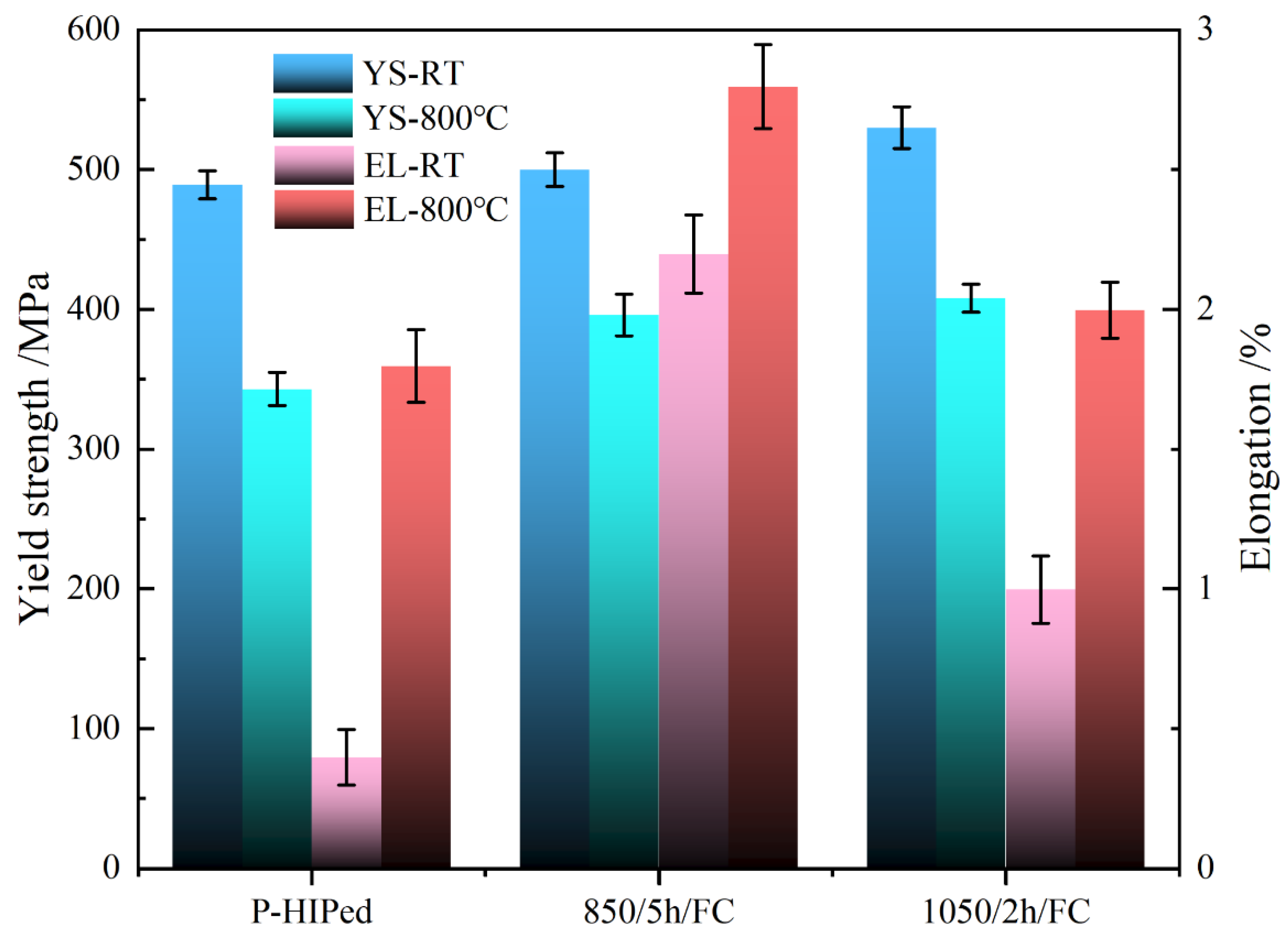
P-HIPed TNM alloys in their initial state and after thermal exposure treatments at 850 °C for 5 h and 1050 °C for 2 h, representing typical microstructures, were selected for tensile tests. For the TNM alloy treated below 850 °C, the microstructure characteristics presented some differences, mainly related to the prevalence of the α2→α2 + γ transformation. The fully lamellar microstructure characteristics after 1050 °C/2 h/FC presented microstructure instability, i.e., the α2→α2 + γ and α2→β0 transformations. The tensile properties at room temperature (RT) and 800 °C are shown in Figure 6. The yield strength (YS) and elongation of the P-HIPed TNM alloy at RT and 800 °C were 489 MPa, <1%, and 343 MPa, 1.8%, respectively. After being exposed at 850 °C for 5 h, both the strength and ductility were improved. The yield strength and ductility were 500 MPa, 2.2% at RT, and 396 MPa, 2.8% at 800 °C. The alloy exposed at 1050 °C for 2 h exhibited obvious enhanced strength (530 MPa at RT, and 408 MPa at 800 °C) and comparable ductility (1.0% at RT and 2.0% at 800 °C) to the P-HIPed state.
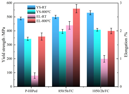
Figure 6.
Tensile properties at RT and 800 °C of P-HIPed TNM alloys with different conditions.
The microstructure near the main crack after tensile testing at 800 °C is shown in Figure 7. It presented a typical brittle fracture, and the crack propagation path was inter-lamellar and trans-lamellar. Since the α2 and γ lamellae have different mechanical properties, the γ phase is softer than the α2 phase [31]. This makes it more likely to cause plastic incompatibility at the colony and interface boundaries [32]. Some secondary cracks were observed at the colony boundary, which propagated mainly along the colony boundary in Figure 7a,b. Due to the α2 and γ strength incompatibility, the stress concentration occurred with the dislocation pile up at the interface of α2/γ [33]. The crack also tended to nucleate within the colony when the value of local stress exceeded the bonding strength of the interface and propagated along with the interface with the plastic increasing [34]. Compared to the untreated P-HIPed TNM alloy, coarse α2 lamellae transformed into fine (α2 + γ) lamellae after the 850 °C/5 h/FC exposure treatment. With the average lamellar spacing decreasing, the high number of interfaces effectively hindered the dislocation movement [35,36]. A secondary crack was also observed inside the colony, and some cracks propagated through the interfacial β0 phases (Figure 7d) as the brittle β0 phase comprising 1.4% percent of the alloy was nano-sized and distributed uniformly at the α2/γ interfaces. Previous research has reported that the interfacial β0 precipitates could effectively block the dislocation motion and twin propagation to improve the creep resistance [37]. The propagation path of the cracks became more tortuous in presentation, which would require more energy to overcome [38]. Therefore, the yield strength was improved. It can be concluded that the nano-scaled interfacial β0 phases provided precipitation strengthening and may be responsible for the strength.
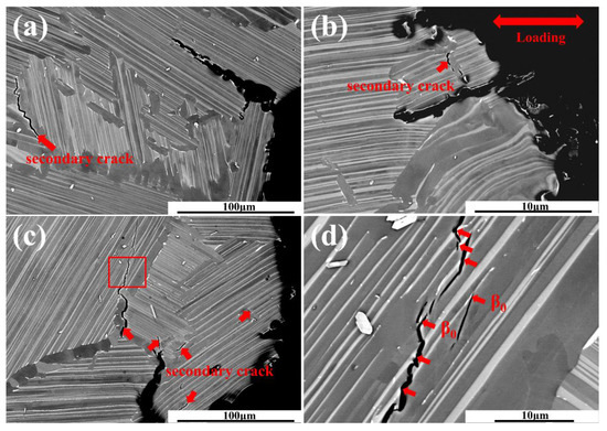
Figure 7.
BSE-SEM micrographs present the near main crack after the 800 °C tensile test. (a) untreated P-HIPed TNM; (b) exposed at 850 °C/5h/FC; (c,d)exposed at 1050 °C/2 h/FC.
4. Conclusions
A fully lamellar microstructure of a TNM alloy was obtained through fabrication by powder hot isostatic pressing at 1260 °C, under a pressure of 170 MPa for 4 h, in which the resulting volume fraction of the β0 phase was only 0.3 ± 0.1%.
When the exposure temperature was below 850 °C, the initial stage of lamellar degeneration was mainly dominated by the α2→α2 + γ transformation. When the exposure temperature was over 950 °C, the α2→α2 + γ and α2→β0 transformations both happened and the β0 phase tended to precipitate within the α2 lamellae.
The tensile properties at RT and 800 °C were improved after short-time high-temperature exposure, i.e., the YS increased from 489 MPa to 530 MPa at RT, and from 343 MPa to 408 MPa at 800 °C. The uniform distribution and nano-scaled interfacial β0 phase provided precipitation strengthening and were not harmful to the elongation.
Author Contributions
Conceptualization, Y.W. and H.K.; Methodology, Y.W. and Z.Y.; Investigation, Y.W. and Y.Y.; Writing—original draft preparation, Y.W.; Writing—review and editing, H.K. and F.Q.; Supervision, H.K., X.X. and J.L. All authors have read and agreed to the published version of the manuscript.
Funding
Research Foundation of the State Key Laboratory of Solidification Processing (NWPU), China under Grant No. 2020-TZ-03 for financial support.
Institutional Review Board Statement
Not applicable.
Informed Consent Statement
Not applicable.
Data Availability Statement
All the data generated during this study are included in this article.
Conflicts of Interest
We declare that we have no financial and personal relationships with other people or organizations that can inappropriately influence our word. There is no professional or other personal interest of any nature or kind in any product, service, or company that could be construed as influencing the position presented in or the review of the manuscript entitled.
References
- Mayer, S.; Erdely, P.; Fischer, F.D.; Holec, D.; Kastenhuber, M.; Klein, T.; Clemens, H. Intermetallic β-Solidifying γ-TiAl Based Alloys–From Fundamental Research to Application. Adv. Eng. Mater. 2017, 19, 1600735. [Google Scholar] [CrossRef]
- Tang, B.; Zhu, B.; Bi, W.; Liu, Y.; Li, J. Effect of Microstructure on the High-Cycle Fatigue Behavior of Ti(43-44)Al4Nb1Mo (TNM) Alloys. Metals 2019, 9, 1043. [Google Scholar] [CrossRef] [Green Version]
- Moritz, J.; Teschke, M.; Marquardt, A.; Stepien, L.; López, E.; Brückner, F.; Barrientos, M.M.; Walther, F.; Leyens, C. Electron Beam Powder Bed Fusion of γ-Titanium Aluminide: Effect of Processing Parameters on Part Density, Surface Characteristics, and Aluminum Content. Metals 2021, 11, 1093. [Google Scholar] [CrossRef]
- Cao, G.X.; Fu, L.F.; Lin, J.G.; Zhang, Y.G.; Chen, C.Q. The relationships of microstructure and properties of a fully lamellar TiAl alloy. Intermetallics 2000, 8, 647–653. [Google Scholar] [CrossRef]
- Wang, J.G.; Hsiung, L.M.; Nieh, T.G. Microstructural instability in a crept fully lamellar TiAl alloy. Intermetallics 1999, 7, 757–763. [Google Scholar] [CrossRef]
- Hu, D.; Wu, X.; Loretto, M.H. Advances in optimisation of mechanical properties in cast TiAl alloys. Intermetallics 2005, 13, 914–919. [Google Scholar] [CrossRef]
- Xu, X.; Lin, J.; Xiang, C.; Liang, Y. Element Distribution and Its Induced Peritectic Reaction during Solidification of Ti-Al-Nb Alloys. Metals 2021, 11, 1386. [Google Scholar] [CrossRef]
- Xiang, L.; Tang, B.; Xue, X.; Kou, H.; Li, J. Microstructural characteristics and dynamic recrystallization behavior of β-γ TiAl based alloy during high temperature deformation. Intermetallics 2018, 97, 52–57. [Google Scholar] [CrossRef]
- Dahar, M.S.; Tamirisakandala, S.A.; Lewandowski, J.J. Evolution of fatigue crack growth and fracture behavior in gamma titanium aluminide Ti-43.5Al-4Nb-1Mo-0.1B (TNM) forgings. Int. J. Fatigue 2018, 111, 54–69. [Google Scholar] [CrossRef]
- Cheng, L.; Li, J.S.; Xue, X.Y.; Tang, B.; Kou, H.C.; Perroud, O.; Bouzy, E. Effect of beta/B2 phase on cavitation behavior during superplastic deformation of TiAl alloys. J. Alloy Compd. 2017, 693, 749–759. [Google Scholar] [CrossRef]
- Schwaighofer, E.; Clemens, H.; Mayer, S.; Lindemann, J.; Klose, J.; Smarsly, W.; Guther, V. Microstructural design and mechanical properties of a cast and heat-treated intermetallic multi-phase gamma-TiAl based alloy. Intermetallics 2014, 44, 128–140. [Google Scholar] [CrossRef]
- Bolz, S.; Oehring, M.; Lindemann, J.; Pyczak, F.; Paul, J.; Stark, A.; Lippmann, T.; Schrüfer, S.; Roth-Fagaraseanu, D.; Schreyer, A.; et al. Microstructure and mechanical properties of a forged β-solidifying γ TiAl alloy in different heat treatment conditions. Intermetallics 2015, 58, 71–83. [Google Scholar] [CrossRef] [Green Version]
- Yan, M.; Yang, F.; Lu, B.; Chen, C.; Sui, Y.; Guo, Z. Microstructure and Mechanical Properties of High Relative Density γ-TiAl Alloy Using Irregular Pre-Alloyed Powder. Metals 2021, 11, 635. [Google Scholar] [CrossRef]
- Schloffer, M.; Iqbal, F.; Gabrisch, H.; Schwaighofer, E.; Schimansky, F.P.; Mayer, S.; Stark, A.; Lippmann, T.; Goken, M.; Pyczak, F.; et al. Microstructure development and hardness of a powder metallurgical multi phase gamma-TiAl based alloy. Intermetallics 2012, 22, 231–240. [Google Scholar] [CrossRef] [Green Version]
- Huang, Z.W.; Zhu, D.G. Thermal stability of Ti-44Al-8Nb-1B alloy. Intermetallics 2008, 16, 156–167. [Google Scholar] [CrossRef]
- Kim, H.Y.; Maruyama, K. Stability of lamellar microstructure of hard orientated PST crystal of TiAl alloy. Acta Mater. 2003, 51, 2191–2204. [Google Scholar] [CrossRef]
- Sharma, G.; Ramanujan, R.V.; Tiwari, G.P. Instability mechanisms in lamellar microstructures. Acta Mater. 2000, 48, 875–889. [Google Scholar] [CrossRef]
- Tian, S.; Lv, X.; Yu, H.; Wang, Q.; Jiao, Z.; Sun, H. Creep behavior and deformation feature of TiAl–Nb alloy with various states at high temperature. Mater. Sci. Eng. A 2016, 651, 490–498. [Google Scholar] [CrossRef]
- Huang, Z.W. Thermal stability of Ti-44Al-4Nb-4Hf-0.2Si-1B alloy. Intermetallics 2013, 37, 11–21. [Google Scholar] [CrossRef]
- Huang, Z.W.; Voice, W.E.; Bowen, P. Thermal stability of Ti–46Al–5Nb–1W alloy. Mater. Sci. Eng. A 2002, 329–331, 435–445. [Google Scholar] [CrossRef]
- Bystrzanowski, S.; Bartels, A.; Clemens, H.; Gerling, R.; Schimansky, F.P.; Dehm, G.; Kestler, H. Creep behaviour and related high temperature microstructural stability of Ti-46Al-9Nb sheet material. Intermetallics 2005, 13, 515–524. [Google Scholar] [CrossRef]
- Huang, Z.W. Ordered ω phases in a 4Zr–4Nb-containing TiAl-based alloy. Acta Mater. 2008, 56, 1689–1700. [Google Scholar] [CrossRef]
- Kastenhuber, M.; Rashkova, B.; Clemens, H.; Mayer, S. Effect of microstructural instability on the creep resistance of an advanced intermetallic gamma-TiAl based alloy. Intermetallics 2017, 80, 1–9. [Google Scholar] [CrossRef]
- Clemens, H.; Wallgram, W.; Kremmer, S.; Guther, V.; Otto, A.; Bartels, A. Design of novel beta-solidifying TiAl alloys with adjustable beta/B2-phase fraction and excellent hot-workability. Adv. Eng. Mater. 2008, 10, 707–713. [Google Scholar] [CrossRef]
- Gerling, R.; Clemens, H.; Schimansky, F.P. Power metallurgical processing of intermetallic gamma titanium aluminides. Adv. Eng. Mater. 2004, 6, 23–38. [Google Scholar] [CrossRef]
- Zhang, D.; Dehm, G.; Clemens, H. Effect of heat-treatments and hot-isostatic pressing on phase transformation and microstructure in a beta/B2 containing gamma-TiAl based alloy. Scr. Mater. 2000, 42, 1065–1070. [Google Scholar] [CrossRef]
- Kastenhuber, M.; Klein, T.; Rashkova, B.; Weissensteiner, I.; Clemens, H.; Mayer, S. Phase transformations in a beta-solidifying gamma-TiAl based alloy during rapid solidification. Intermetallics 2017, 91, 100–109. [Google Scholar] [CrossRef]
- Lamirand, M.; Bonnentien, J.L.; Ferriere, G.; Guerin, S.; Chevalier, J.P. Effects of interstitial oxygen on microstructure and mechanical properties of Ti-48Al-2Cr-2Nb with fully lamellar and duplex microstructures. Met. Mater. Trans. A 2006, 37a, 2369–2378. [Google Scholar] [CrossRef]
- Kainuma, R.; Fujita, Y.; Mitsui, H.; Ohnuma, I.; Ishida, K. Phase equilibria among α (hcp), β (bcc) and γ (L10) phases in Ti–Al base ternary alloys. Intermetallics 2000, 8, 855–867. [Google Scholar] [CrossRef]
- Denquin, A.; Naka, S. Phase transformation mechanisms involved in two-phase TiAl-based alloys—II. Discontinuous coarsening and massive-type transformation. Acta Mater. 1996, 44, 353–365. [Google Scholar] [CrossRef]
- Song, L.; Xu, X.J.; You, L.; Liang, Y.F.; Wang, Y.L.; Lin, J.P. Ordered alpha(2) to omega(o) phase transformations in high Nb-containing TiAl alloys. Acta Mater. 2015, 91, 330–339. [Google Scholar] [CrossRef]
- Chan, K.S.; Kim, Y.W. Relationships of Slip Morphology, Microcracking, and Fracture-Resistance in a Lamellar Tial-Alloy. Met. Mater. Trans. A 1994, 25, 1217–1228. [Google Scholar] [CrossRef]
- Schloffer, M.; Rashkova, B.; Schoberl, T.; Schwaighofer, E.; Zhang, Z.L.; Clemens, H.; Mayer, S. Evolution of the omega(o) phase in a beta-stabilized multi-phase TiAl alloy and its effect on hardness. Acta Mater. 2014, 64, 241–252. [Google Scholar] [CrossRef]
- Zhang, S.; Tian, S.; Lv, X.; Yu, H.; Tian, N.; Jiao, Z.; Zhao, G.; Li, D. Deformation and damage behaviors of as-cast TiAl-Nb alloy during creep. Prog. Nat. Sci. Mater. Int. 2018, 28, 618–625. [Google Scholar] [CrossRef]
- Schillinger, W.; Clemens, H.; Dehm, G.; Bartels, A. Microstructural stability and creep behavior of a lamellar gamma-TiAl based alloy with extremely fine lamellar spacing. Intermetallics 2002, 10, 459–466. [Google Scholar] [CrossRef]
- Zhu, H.; Seo, D.Y.; Maruyama, K.; Au, P. Effect of lamellar spacing on microstructural instability and creep behavior of a lamellar TiAl alloy. Scr. Mater. 2006, 54, 1979–1984. [Google Scholar] [CrossRef]
- Zhu, H.; Seo, D.; Maruyama, K.; Au, P. Strengthening of a fully lamellar TiAl+W alloy by dynamic precipitation of β phase during long-term creep. Scr. Mater. 2006, 54, 425–430. [Google Scholar] [CrossRef]
- Zhang, S.; Cui, N.; Sun, W.; Li, Q. Microstructural Characterization and Crack Propagation Behavior of a Novel β-Solidifying TiAl Alloy. Metals 2021, 11, 1231. [Google Scholar] [CrossRef]


Publisher’s Note: MDPI stays neutral with regard to jurisdictional claims in published maps and institutional affiliations. |
© 2021 by the authors. Licensee MDPI, Basel, Switzerland. This article is an open access article distributed under the terms and conditions of the Creative Commons Attribution (CC BY) license (https://creativecommons.org/licenses/by/4.0/).