Abstract
High speed tool steels are materials that exhibit superior mechanical properties (e.g., high hardness). They should also be resistant to thermal exposure to maintain high hardness during the machining process. In this paper, a C-free tool steel formed of Fe matrix and a Mo6Co7 intermetallic phase was studied. This steel was compared to the well-known Vanadis 60 steel containing Fe matrix and carbides. Microstructures were investigated by scanning (SEM) and transmission (TEM) electron microscopy, and the mechanical properties and thermal stability of both materials were compared. It was proven that the strengthening in the Vanadis 60 steel was mainly caused by the carbides, while the C-free steel was strengthened by the Mo6Co7 phase. The hardness values of both materials were comparable in the utilization state (approx. 950 HV). The hardness of Vanadis 60 steel decreased after several minutes of annealing at 650 °C under the value that enables material utilization. The hardness value of the steel strengthened by the intermetallics also decreased but significantly slower. Based on these results, the main finding of this study is that the C-free steel exhibited much better thermal stability and may be utilized at higher temperatures for longer periods of time than Vanadis 60.
1. Introduction
High-speed tool steels are materials used in cutting tools for the machining of other materials. Due to this function, there are high demands on their mechanical properties. To obtain these properties, the steels are also processed either by conventional ingot metallurgy or modern materials by powder metallurgy [1]. The tool steels are delivered in a soft state when they can be shaped by machining. After achieving the desired shape, the materials are heat treated to obtain maximum hardness and wear resistance [1].
The traditional high speed tool steels contain a high amount of carbon and other alloying elements with different functions: Cr is responsible for the formation of different types of carbides depending on the exact processing temperature [2,3,4,5]. These phases dissolve during austenitization in the sequence M23C6, M7C3, M6C, MC [6], or according to [7] in the sequence M7C3, M23C6, MC, M2C, and/or M6C. These Cr and C containing phases are responsible for the great hardenability of high speed steels [8] caused by the formation of secondary carbides after the heat treatment. Mo and W lower the solidus temperature and together with Fe form the M6C carbides [9]. It has been described that when these carbides are formed, they dissolve in a limited extent during the heat treatment [2]. V addition reduces the grain size of the matrix and also leads to the formation of the MC type of carbide that improves abrasion resistance due to its hardness [2]. Co does not form any carbides in the matrix. Its addition shifts the solidus temperature up and so increases the effect of the heat treatment, which allows Co containing tool steel to have an extremely high hardness (67–70 HRC). Addition of Co also increases the thermal stability of the steel [2]. These were the reasons for the selection of Vanadis 60 steel for this study. As it contains an increased amount of Co, it is dedicated for cold work tools, where the highest possible wear resistance, and at the same time, the highest possible compressive strength is required [10].
The high-end tool steel Vanadis 60 was compared with the carbon-free highly alloyed tool steel (hereafter referred to as the PM+ steel in this study). This is a carbon-free steel reinforced by intermetallics. The first article about this type of C-free tool material had been published in 1932 by Köstner and Tonn [11] and the materials were found to be very promising due to their high hardness and thermal stability during operation. The increase in hardness connected with intermetallic precipitation was studied in numerous works [12,13,14,15,16]. Additional works proved that the microstructure of a precipitation hardenable alloy is formed by spinodal decomposition of austenite [17,18]. In the coarse-grained materials, the areas rich in Mo are quite brittle. This problem can be solved by involvement of powder metallurgy (PM) to the production [19]. As an example, the PM steel (Fe-25 wt. %Co–25 wt. % Mo) was extremely hard (71 HRC) and its hardness did not decrease under 60 HRC during exposure at 700 °C [19]. Numerous works have been devoted to the description of precipitation mechanisms [20,21,22,23], which included the formation of various precipitates with the composition of (Fe, Co)7Mo6 [24].
The aim of this work was to compare the microstructure evolution and thermal stability of the common Vanadis 60 tool steel and uncommon C-free highly alloyed PM+ tool steel.
2. Materials and Methods
Two types of high speed tool steel were compared in this article: one was Vanadis 60 and the other was carbon-free steel PM+ (sometimes also labelled as MC90 [25]). Chemical compositions of both steels are given in Table 1.

Table 1.
Chemical composition of the studied steel given in wt. %.
Although the chemical compositions of both materials were quite different, they were processed in the similar way. In the first step, the materials were produced by powder metallurgy including the melt atomization forming the rapidly solidified powders. The following step was hot isostatic pressing of powders to produce bulk semiproducts. After the bulk material preparation, the steels were annealed with the aim to obtain a soft state suitable for machining of the material. The steels were annealed at temperatures of 850–900 °C for 3 h and subsequently furnace cooled to 700 °C with the cooling rate of 10 K/h. Subsequent cooling to room temperature was performed in an air atmosphere. The material subjected to this process was called in the “soft state” in this paper. When the desired size and shape of samples were obtained (for bending tests, a rod with diameter of 10 mm and length of 220 mm; for other test cylinders with diameter of 20 mm and high of 10 mm), the materials were heat treated with the aim to reach the maximum hardness. The heat treatment consisted of (1) austenitization; (2) quenching; and (3) tempering. For the Vanadis 60 steel, the austenitization process consisted of these heating steps: (1) heating up to 650 °C with a dwell time of 20 min; (2) heating up to 830 °C with a dwell time 20 min; and (3) heating up to 1180 °C (austenitization temperature) with a dwell time of 2 min. Austenitization was followed by gas-quenching to the temperature of 540 °C and subsequent air-quenching to room temperature. The third step, tempering, was conducted at 540 °C for 1 h followed by air cooling. The tempering was repeated three times.
For the PM+ steel, the austenitization was performed at a temperature of 1190 °C with the dwell time of 30 min. This was followed by oil quenching with subsequent tempering at 509 °C for 3 h. The materials subjected to this heat treatment were labelled in the “heat treated (HT) state”.
Microstructures of the steels were observed using scanning electron microscope (SEM) TESCAN VEGA 3 LMU (TESCAN, Brno, Czech Republic, accelerating voltage of 20 kV) equipped with an energy dispersive spectrometer (EDS, dwell time for point analysis of 60 ms of life time, and 10 ms for EDS mapping) by Oxford Instruments. The samples were prepared by grinding and polishing followed by etching in a Nital 5 agent (5 vol. % of HNO3 solution in ethanol) for 3 s. Detailed observation was performed by means of transmission electron microscope (TEM) Jeol 2200 FS equipped with an energy dispersive spectrometer (EDS, dwell time for point analysis of 60 ms of life time, and 10 ms for EDS mapping, spot size of 1 nm) made by Oxford Instruments and utilizing the in-column energy filter. The EFTEM (energy filtered TEM) images were obtained by means of the three windows method with a 20 eV energy slit using a TVIPS camera (TVIPS, Munich, Germany) with software EM menu (for carbon, the three windows were at 250, 270 and 294 eV, and for iron, the three windows were 675, 695, and 718 eV). The TEM samples were prepared by ion polishing using Gatan PIPs equipment (energy of beam of 5 keV, dual rotation). Software ImageJ 1.43 was used for image analysis of the micrographs. For each average value, at least 100 actual values were measured. The experimental errors were estimated as the standard deviations.
Phase composition was measured by X-ray diffraction (XRD) using a Bruker ASX D8 spectrometer with Co anode with a PIXcel1D detector, 10 mm mask, voltage of 35 kV, current of 35 mA, 0.016 mm Fe beta-filter, step of 0.0394°, and measuring time per step of 355 s.
Mechanical properties were characterized by means of Vickers hardness (HV30) and by the three point bending test. For the bending test, the rod shaped samples had a diameter of 10 mm and a length of 220 mm. The distance between bending points was 160 mm and the deformation speed was 5 mm/min. These measurements were performed using the universal testing device LabTest 5.250SP1-VM.
The wear resistance testing was performed using a TRIBOtester made by TRIBOtechnik in the linear reciprocation ball-on-disc regime. The ball had a diameter of 6 mm and was made from Al2O3. As a disc, the studied materials were used with a normal load N of 5 N, sliding speed of 10 mm s−1, and sliding length of 20,000 mm with excentre of 5 mm.
The thermal stability of materials was tested by their annealing in the range of 600–800 °C and measuring of the Vickers hardness on the initial sample and samples annealed for selected periods (each 1 h for temperature of 600, 650, and 700 °C and each 10 min for temperature of 800 °C). The setup for hardness measurement was a standard one with a load of 30 kg and was performed using VEB Werkstoffprüfmaschinen Leipzig equipment. The temperatures of annealing were chosen according to the assumed operation conditions: the temperatures of 600 and 650 °C should simulate non optimal cooling during the utilization of tools manufactured from the studied materials. However, they should not affect either the Vanadis 60 or MP+ steel. The temperature of 700 °C was too high for the majority of high-speed tool steels, however, it may still be acceptable for PM+ steel. The temperature of 800 °C simulates the failure of a cooling system.
3. Results and Discussion
3.1. Microstructure
Figure 1 compares an overview of the microstructures of the Vanadis 60 steel in the soft state and in the HT state. The contents of carbides determined by image analysis were 26.1 area % in the soft state and decreased to 14.9 area % in the HT state.
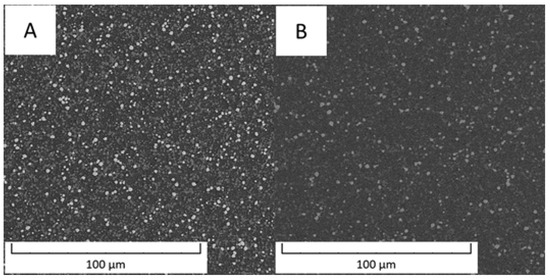
Figure 1.
Microstructure of Vanadis 60 steel (A) in the soft state and (B) in the HT state (SEM-BSE).
Detailed micrographs, presented in Figure 2, show that in the Vanadis 60 steel, there were two types of carbides with different chemical compositions (labelled by red and blue arrow in Figure 2). The size of these particles was too small to exactly measure their composition by EDS in SEM. In the soft state (Figure 2A), it was also observed that there were two sized groups of the carbides—large ones labelled by red and blue arrows and small ones labelled by green arrows. The average sizes of the observed particles are given in Table 2.
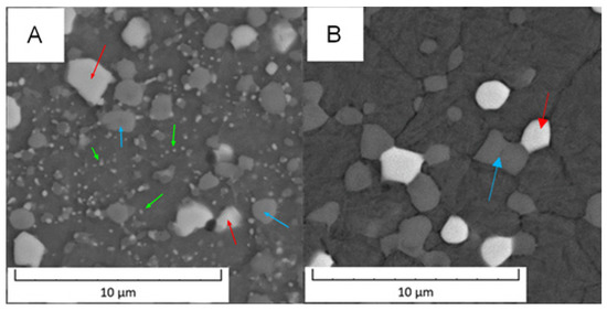
Figure 2.
Detailed microstructure of the Vanadis 60 steel (A) in the soft state and (B) in the HT state (SEM-BSE).
Table 2.
Size of the carbide particles in Vanadis 60 steel.
Based on the micrographs in Figure 2 and the results given in Table 2, the small carbides dissolved during the heat treatment and the large carbides remained unaffected.
The EDS mapping in the TEM was performed to distinguish those two types of carbides and the results are given in Figure 3 and Figure 4. In both states, the matrix was composed of Fe and Co, the large bright carbides contained Mo and W, and the large dark carbides contained mainly V and Mo, W, and Cr. The elemental distribution (mainly of Cr) in the soft state indicated that the small carbides were formed predominantly by Cr-based carbides (corresponding to the bright carbides observed in SEM-BSE and TEM-HAADF). The discrepancy with thee observation in Figure 2A might be caused by limitations of the SEM observation (bright appearance of some particles was caused not by chemical contrast, but by edge contrast for conveniently oriented particles).
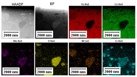
Figure 3.
TEM-EDS maps of the Vanadis 60 steel in the soft state.
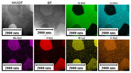
Figure 4.
TEM-EDS maps of the Vanadis 60 steel in the HT state.
The elemental distribution of the Vanadis 60 steel in the HT state shown in Figure 4 confirmed the dissolution of small Cr-rich particles into the matrix.
The average composition of both types of large carbides is given in Table 3. The content of C was not quantified because of the limitation of the EDS method.
Table 3.
Average composition of carbide particles in Vanadis 60 steel in the application state determined by TEM-EDS, given in wt. %.
The phase composition of Vanadis 60 steel was determined by XRD and the results are shown in Figure 5. It was confirmed that two types of carbides were present in the material. The carbides that appeared dark in the SEM-BSE (back scattered electrons) micrographs due to their high V content were assigned to the MC type and the powder diffraction card used in the XRD for their identification was 01-073-0476. The bright carbides were M6C type (pdf card 01-089-7205). The M23C6 type was also detected in a small amount and the 01-089-2724 pdf card was used for XRD identification. Presence of the expected M7C3 carbide was not detected. It is slightly surprising as it is referred to as being present in similar material [26,27]. On the other hand, it was already observed that the M7C3 carbide was not present in the material while the M23C6 carbide was detected [28,29]. The type of formed carbides is strongly dependent on conditions of heat treatment. No change in the composition was observed between the soft state (black curve, SS) and the HT state (red curve, AS), which is in agreement with SEM observations in Figure 1 and Figure 2, because the small particles are not detectable by XRD.
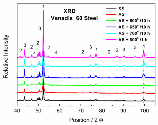
Figure 5.
XRD patterns of Vanadis 60 steel, SS—soft state, AS—HT state, 1—Fe matrix, 2—M6C, 3—MC, 4—M23C6.
TEM observation was conducted to particularly compare the matrix in the soft and the HT state. In the soft state, the small particles of carbides (labelled by red arrows) were found in the matrix, as shown in Figure 6. Such particles were not visible in the HT state (Figure 7), but on the other hand, in the matrix, there was twinned martensite (labelled by green arrows) present as a residue of the heat treatment [30].
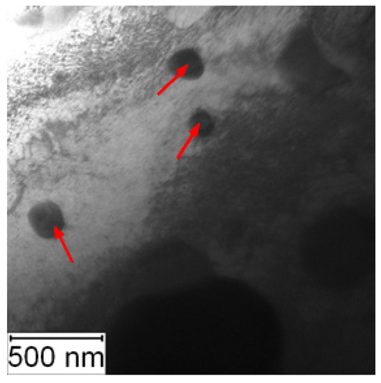
Figure 6.
TEM micrograph of Vanadis 60 in the soft state (red arrows—carbides).
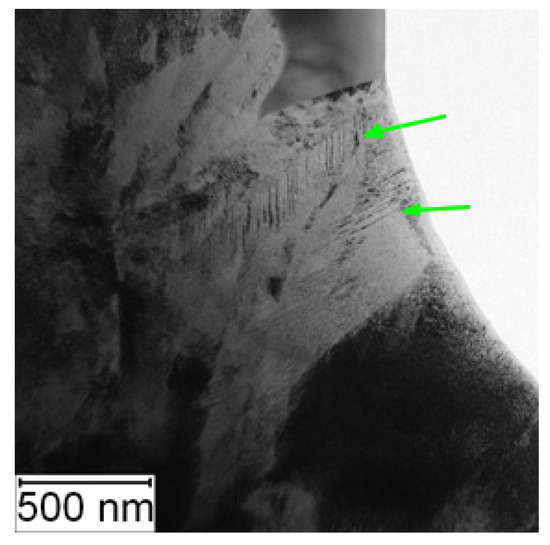
Figure 7.
TEM micrograph of Vanadis 60 in the HT state (green arrows—twinned martensite).
To verify the presence of nanosized carbides in the matrix in the HT state, the EDS mapping was not sufficient due to spatial resolution of EDS (the spot size was 1 nm). Because of this reason, EFTEM imaging was performed to obtain better resolution (full resolution of the camera, 4K). In Figure 8A, the microstructure of Vanadis 60 steel in the HT state is shown. Figure 8B shows the EFTEM image of the same area with the energy shift of 284 eV corresponding to the K edge of carbon. The bright area in the left upper corner (labelled by the blue arrow) is a large carbide particle. The dark line (labelled by the red arrow) is a depleted zone and in the middle of the micrograph, there is the matrix with small carbon containing particles appearing bright (labelled by green arrows). These particles can be considered as secondary M23C6 carbides with the role of strengthening precipitates [2].
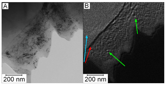
Figure 8.
Micrograph of Vanadis 60 steel in the HT state: (A) TEM and (B) EFTEM with an energy shift of 284 eV (carbon, K edge).
The other material described in this paper is a carbon-free steel PM+ that is reported to be strengthened by rhombohedral intermetallic phase Mo6Co7, labelled also as the µ phase [20]. The microstructure of PM+ steel is shown in Figure 9. The area fraction of intermetallic particles was 24.7% in the soft state (Figure 9A) and only 5.1% in the HT state (Figure 9B).
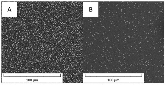
Figure 9.
Microstructure of the PM+ steel (A) in the soft state and (B) in the HT state (SEM-BSE).
Detailed observation of the PM+ steel is shown in Figure 10. In the soft state (Figure 10A), binodal distribution of particle sizes was observed. The large particles had a size of 2.2 ± 0.5 µm and irregular or ragged shape. The small particles had a size of 0.7 ± 0.3 µm. The microstructure of PM+ steel in the HT state (Figure 10B) contained only particles with a size of 1.4 ± 0.5 µm and their shape was almost spheroidized with elongation along the grain boundaries.
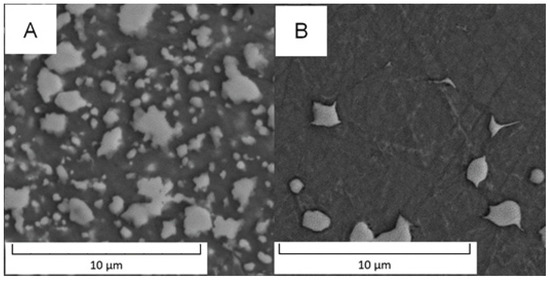
Figure 10.
Detailed microstructure of PM+ steel (A) in the soft state and (B) in the HT state (SEM-BSE).
The distribution of elements measured by TEM-EDS is shown in Figure 11. The particles (both small and large ones) contained Co, Mo, and Si, while the matrix was formed by Fe and Co.
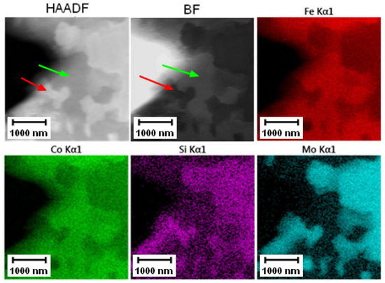
Figure 11.
TEM-EDS maps of the PM+ steel in the soft state, green arrow—matrix, red arrow—Mo6Co7 phase.
The results of TEM-EDS given in Figure 12 mapping the PM+ steel in the HT state proved the observations of the SEM in Figure 10B. The small particles dissolved in the matrix and the large particles had a spherodized roundish shape with elongation in the direction of the grain boundaries.
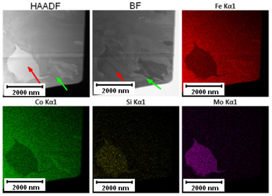
Figure 12.
TEM-EDS maps of the PM+ steel in the HT state, green arrow—matrix, red arrow—Mo6Co7 phase.
The average composition of the matrix and particles is given in Table 4. The theoretical composition of the Mo6Co7 phase was 58 wt. % of Mo and 42 wt. % of Co. Increased content of Mo was observed in the particles, but the content of Co in them was lower than the nominal composition shown in Table 1. This explanation might be the partial substitution of Co by Fe. The other reason that would also explain the lower content of Mo in particles is overlapping of the particles with the matrix.
Table 4.
Average composition of matrix and intermetallic particles in PM+ steel in the application state determined by TEM-EDS, given in wt. %.
According to the results of the XRD, the particles were indeed formed by the Mo6Co7 phase, where part of Co was substituted by Fe. In the case of PM+ steel, the diffraction pattern of the material in the soft state (black curve in Figure 13) exhibited a significantly higher amount of the Mo6Co7 phase than the material in the HT state (red curve in Figure 13). This is in agreement with the SEM observations in Figure 9 and Figure 10 where a decreased amount of intermetallic particles was observed due to their dissolution.
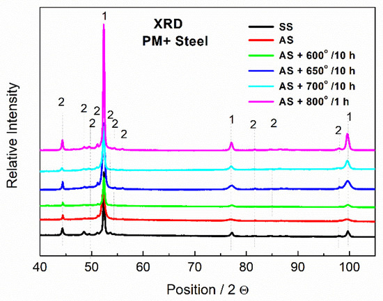
Figure 13.
XRD patterns of MP+ steel, SS—soft state, AS—HT state, 1—Fe matrix, 2—Mo6Co7.
Increased amount of intermetallic phase precipitates in the matrix was also observed by the TEM, as shown in Figure 14 and Figure 15.
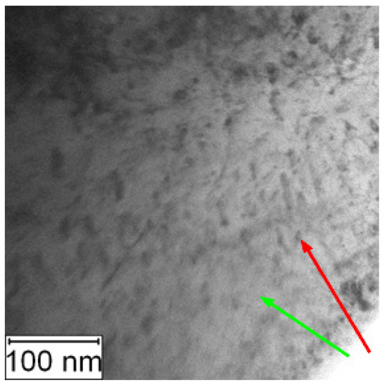
Figure 14.
TEM micrograph of PM+ in the soft state, green arrow—matrix, red arrow—Mo6Co7 precipitate.
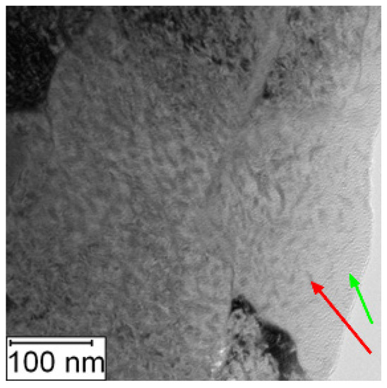
Figure 15.
TEM micrograph of PM+ in the HT state, green arrow—matrix, red arrow—Mo6Co7 precipitate.
To prove that the observed features were nanosized particles of the Mo6Co7 phase, EFTEM imaging was performed. In Figure 16A, the microstructure of PM+ steel in the HT state is shown. Figure 16B shows the EFTEM image of the same area with the energy shift of 708 eV corresponding to the L3 edge of Fe. Areas with a size about 5–10 nm depleted in Fe appeared as dark places in Figure 16B. These results correspond to the 3DAP measurements presented in [23].
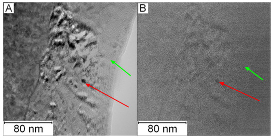
Figure 16.
Micrograph of PM+ steel in the HT state: (A) TEM and (B) EFTEM with an energy shift of 708 eV (iron, L3 edge), green arrow—matrix, red arrow—Mo6Co7 precipitate.
3.2. Mechanical Properties
The bending test was chosen for the description of mechanical properties as it combines tensile and compression stress and because of this, it is close to the real stresses in material during its utilization. Typical bending curves of the materials are shown in Figure 17. Both materials in the soft state exhibited similar mechanical behavior consisting from the elastic region and plastic region. The flexural strength of Vanadis 60 steel reached values of 1993 ± 19 MPa and the value of PM+ steel was 2346 ± 17 MPa.
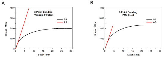
Figure 17.
Three point bending curves of (A) Vanadis 60 steel and (B) PM+ steel in the soft state (SS) and in the HT state (AS).
Both materials in the HT state exhibited the change in mechanical properties toward brittle behavior compared to the soft state. In the case of Vanadis 60 steel, the heat treatment led to significant increase in flexural strength (3922 ± 58 MPa). Precipitation of secondary M23C6 carbides is supposed to be responsible for this change. The flexural strength of PM+ steel in the HT state (2162 ± 98 MPa) did not increase compared to the soft state, but the mechanism of deformation was different due to the shape of the bending curve. This change in mechanical properties was already observed for the materials with similar compositions as the PM+ steel [19], although the heat treatment process that the material underwent was slightly different (e.g., quenching into oil bath). The explanation for the change in deformation mechanism is the precipitation of the Mo6Co7 intermetallic phase. The strength of material in the soft state is derived mainly from solid solution strengthening, while in the HT state, the main strengthening factor is precipitates. These two mechanisms are contradictory.
The fracture surfaces of Vanadis 60 steel are shown in Figure 18. Although the behavior of the material in the soft state and in the HT state was different, the fracture surfaces looked similar and only a limited plastic deformation was observed in the soft state. The main difference was that in the HT state, some of the M23C6 carbides were cracked (labelled by red arrow in Figure 18D) and some carbide particles were ribbed out (labelled by blue arrow in Figure 18D).
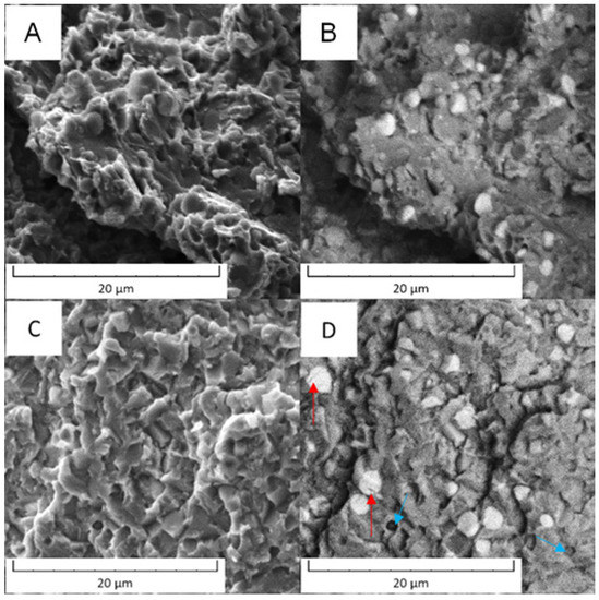
Figure 18.
Fracture surface of the Vanadis 60 steel: (A) in the soft state (SEM-SE), (B) in the soft state (SEM-BSE), (C) in the HT state (SEM-SE), (D) in the HT state (SEM-BSE).
In the case of PM+ steel, the morphology was cleavage type. The fracture surfaces did not exhibit signs of plastic deformation and the cracks were located in the matrix in both states of material, as documented in Figure 19. The intermetallic particles (labelled by red arrows) may have stopped the progress of the cracks or were circumvented by the cracks.
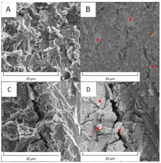
Figure 19.
Fracture surface of the PM+ steel: (A) in the soft state (SEM-SE), (B) in the soft state (SEM-BSE), (C) in the HT state (SEM-SE), (D) in the HT state (SEM-BSE).
3.3. Thermal Stability
To prove the thermal stability, both steels were annealed at 600, 650, 700, and 800 °C for different periods of time and hardness was measured. Results are plotted in Figure 20. At all temperatures, the thermal stability of PM+ steel was significantly better because the hardness values after annealing decreased much more slowly than in the case of Vanadis 60 steel. The minimum hardness for utilization of high speed tool steels is about 64 HRC [31], which approximately corresponds to 850 HV30 [32]. As illustrated in Figure 20A, both steels may be exposed to the temperature of 600 °C for a few hours without losing their functionality. In addition, the PM+ steel may survive even at temperatures of 650 and 700 °C (Figure 20B,C) for several minutes. In contrast, the Vanadis 60 steel lost its hardness quickly at these temperatures. Exposure at 800 °C (Figure 20D) is harmful for both studied materials.
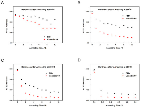
Figure 20.
Dependence of hardness HV30 on annealing time at (A) 600 °C, (B) 650 °C, (C) 700 °C, (D) 800 °C.
Wear resistance was measured on the steels in the HT state and after annealing at 600 and 650 °C and the results are given in Table 5.
Table 5.
Wear rate of Vanadis 60 and PM+ steels in the HT state and after annealing.
The values in Table 5 imply that the Vanadis 60 steel had surprisingly higher wear resistance than the PM+ steel and its values do not depend on temperature. This discrepancy can be explained when wear tracks are observed, as shown in Figure 21. The wear tracks of Vanadis 60 contain a high amount of oxide particles (appearing dark in Figure 21), not allowing for an accurate estimation of the wear rates.
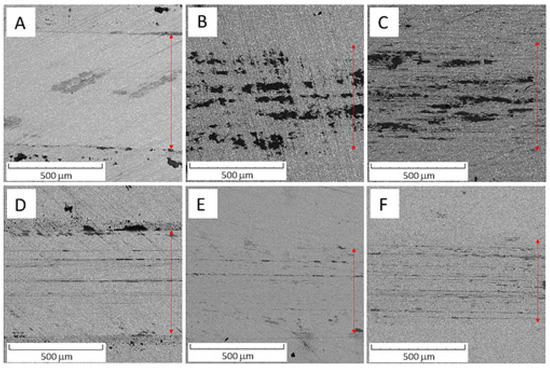
Figure 21.
SEM-BSE micrograph of (A) Vanadis 60 steel in the HT state, (B) Vanadis 60 steel in the HT state after annealing at 600 °C/10 h, (C) Vanadis 60 steel in the HT state after annealing at 650 °C/10 h, (D) PM+ steel in the HT state, (E) PM+ steel in the HT state after annealing at 600 °C/10 h, (F) PM+ steel in the HT state after annealing at 650 °C/10 h.
The microstructure evolution after annealing of Vanadis 60 steel is illustrated in Figure 22. The microstructure after annealing at 600 °C for 10 h (Figure 22C) did not exhibit any change compared to the microstructure in the HT state (Figure 22B), although the hardness of this material had already decreased. In the microstructures of materials annealed at 650 °C and 700 °C for 10 h and at 800 °C for 1 h, small carbide particles (Figure 22D,E) were evident. Compared to the microstructure of the soft state (Figure 22A), these secondary carbides were finer and more frequent.
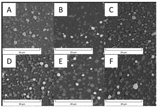
Figure 22.
SEM micrograph of Vanadis 60 steel (A) in the soft state, (B) in the HT state, (C) in the HT state after annealing at 600 °C/10 h, (D) in the HT state after annealing at 650 °C/10 h, (E) in the HT state after annealing at 700 °C/10 h, (F) in the HT state after annealing at 800 °C/1 h.
The detailed observation of Vanadis 60 steel after annealing at 800 °C for 1 h, as shown in Figure 23, revealed the presence of carbide particles of different sizes (about hundreds nm, dark areas) located in the matrix and some at the grain boundaries.
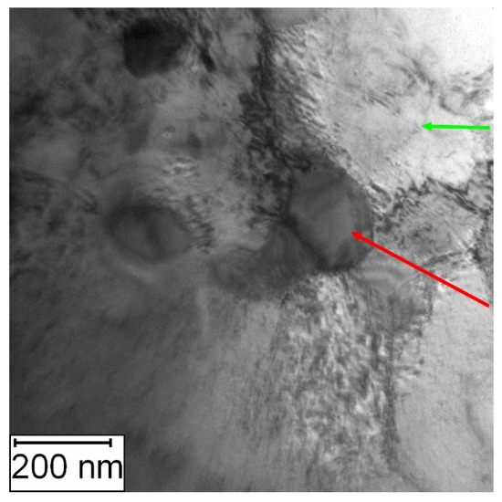
Figure 23.
TEM micrograph of the Vanadis 60 steel in the HT state after annealing at 800 °C/1 h, green arrow—matrix, red arrow—M23C6 carbide.
The elemental distribution visualized by TEM-EDS mapping (Figure 24) confirmed the previous results. The small carbide particles were, according to their composition and XRD pattern in Figure 5, mainly formed by the M6C and M23C6 phases. The material almost returned to its equilibrium state during annealing, which is close to the soft state discussed previously. The hardness of Vanadis 60 steel in the soft state is 35 HRC [33], corresponding to 340 HV30 [32]. The hardness value of the material after annealing at 800 °C/1 h presented in this paper was approximately 450 HV30 (see Figure 20), which approached the soft state.
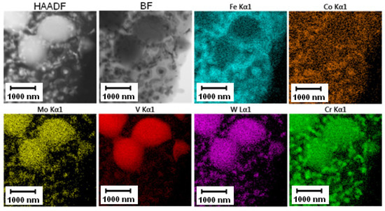
Figure 24.
TEM-EDS maps of the Vanadis 60 steel after annealing at 800 °C for 1 h.
The evolution of the microstructure of PM+ steel with annealing temperature is shown in Figure 25. The samples after annealing at 600 and 650 °C for 10 h (Figure 25C,D) did not exhibit any changes in the microstructure compared to the material in the HT state (Figure 25B). After annealing at 700 °C for 10 h, small intermetallic particles emerged in the material—some of them randomly, but a part of them were interconnected in small chains marked by red ellipses in Figure 25E. This observation is in contradiction with [19], where the stability of this type of material at 700 °C was claimed. The amount of fine secondary intermetallic particles observed in PM+ steel after annealing at 800 °C/1 h was high, as visible in Figure 25F. Unlike the Vanadis 60 steel, the microstructure of PM+ steel did not return to its initial (soft) state (Figure 25A). The large intermetallic particles almost preserved their regular shape, and the small particles were significantly finer (Figure 25A,F).
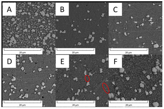
Figure 25.
SEM micrograph of PM+ steel (A) in the soft state, (B) in the HT state, (C) in the HT state after annealing at 600 °C/10 h, (D) in the HT state after annealing at 650 °C/10 h, (E) in the HT state after annealing at 700 °C/10 h, red ellipses—chains of carbides, (F) in the HT state after annealing at 800 °C/1 h.
The TEM micrographs in Figure 26 and Figure 27 present the microstructure of PM+ steel after annealing at 800 °C for 1 h. The occurrence of fine intermetallic particles is obvious in Figure 26. The coarsening of the precipitates is shown in Figure 27. The finest precipitates in this case were about 50 nm, while in the application state (Figure 16), they were less than 10 nm.
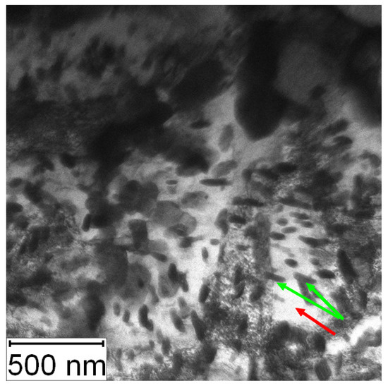
Figure 26.
TEM micrograph of the PM+ steel in the HT state after annealing at 800 °C/1 h, green arrow—matrix, red arrow—Mo6Co7 precipitates.
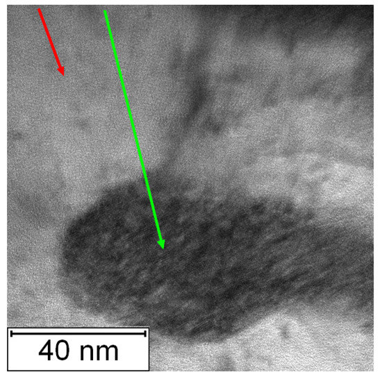
Figure 27.
Detailed TEM micrograph of the PM+ steel in the HT state after annealing at 800 °C/1 h, green arrow—matrix, red arrow—Mo6Co7 precipitate.
The TEM-EDS mapping of annealed PM+ steel, given in Figure 28, confirmed the previously shown results. The fine intermetallic particles were large enough to be distinguishable by EDS analysis, but their size and shape did not achieve the situation in the soft state as in the case of Vanadis 60 steel.
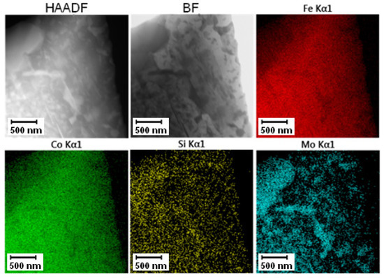
Figure 28.
TEM-EDS maps of the PM+ steel after annealing at 800 °C for 1 h.
The difference in high temperature behavior between the two studied materials may lie in the different diffusion coefficients of individual elements in the iron matrix. It has already been proven that the precipitation of the Mo6Co7 phase is driven by the diffusion of Mo in the Fe matrix [19]. The diffusion rate of Mo in the Fe matrix was even lower than the Fe self-diffusion [34], while the diffusion coefficient of C in the Fe matrix (driving force for carbide precipitation) was significantly higher [35].
4. Conclusions
Two high speed steels were compared in this paper. Both materials had very fine microstructure originating from their processing by powder metallurgy. The Vanadis 60 steel was formed by the Fe matrix and three types of carbides—MC phase formed predominantly by C, V, Wo, and Mo; M6C phase containing C, W, Mo, and Fe; and the secondary M23C6 phase formed during heat treatment. The microstructural changes during heat treatment (from the soft state to the HT state) and during subsequent annealing were connected mainly with the M23C6 phase. The PM+ steel was composed by the Fe matrix and intermetallic Mo6Co7 phase that is dissolving and precipitating according to the heat treatment of the material.
Both steels exhibited plastic deformation in the soft state with the flexural strength of approximately 2000 MPs. In the HT state, both steels exhibited brittle behavior, but the values of flexural strength differed—the value for the PM+ steel was comparable with the soft state, but the value for Vanadis 60 almost doubled. These results prove that the strengthening function of carbide particles is more efficient that the one of intermetallics.
On the other hand, measurement of hardness after annealing proved that the strengthening effect of intermetallic particles of the Mo6Co7 phase retained higher temperatures and for a longer time. As a result, significantly higher thermal stability was observed for the PM+ steel.
The obtained results show that neither of the studied materials can be replaced by the other. The more traditional Vanadis 60 steel exhibited excellent properties during low temperature utilization while the PM+ steel was more suitable for elevated temperatures.
Author Contributions
A.M. writing—original draft preparation, investigation (SEM); D.V. writing—review and editing; V.P. investigation (metallography); J.K. investigation (bending tests); J.Š. investigation (hardness measurements); Z.K. investigation (TEM sample preparation); P.N. investigation (tribology). All authors have read and agreed to the published version of the manuscript.
Funding
The authors acknowledge the assistance provided by the Research Infrastructure NanoEnviCz, supported by the Ministry of Education, Youth and Sports of the Czech Republic under Project No. LM2018124. This work was supported from the grant of Specific univerzity research—Grant No. A1_FCHT_2021_010.
Institutional Review Board Statement
Not applicable.
Informed Consent Statement
Not applicable.
Data Availability Statement
Not applicable.
Conflicts of Interest
The authors declare no conflict of interest.
References
- Roberts, G.; Krauss, G.; Kenedy, R. Chapter 14—High speed steel. In Tool Steels, 5th ed.; ASM International: Metals Park, OH, USA, 1998; pp. 251–290. [Google Scholar]
- Højerslev, C. Tool Steels; Forskningscenter Risoe: Roskilde, Denmark, 2001; ISBN 87-550-2833-0. [Google Scholar] [CrossRef]
- Liu, B.; Qin, T.; Xu, W.; Jia, C.; Wu, Q.; Chen, M.; Liu, Z. Effect of Tempering Conditions on Secondary Hardening of Carbides and Retained Austenite in Spray-Formed M42 High-Speed Steel. Materials 2019, 12, 3714. [Google Scholar] [CrossRef]
- Guo, J.; Liao, B.; Liu, L.; Gao, Y.; Ren, J.; Yang, Q. Composition Optimization and Experimental Characterization of a Novel Steel Based on CALPHAD. J. Mater. Eng. Perform. 2015, 24, 2099–2107. [Google Scholar] [CrossRef][Green Version]
- Godec, M.; Balantič, D.A.S. Coarsening behaviour of M23C6 carbides in creep-resistant steel exposed to high temperatures. Sci. Rep. 2016, 6, 29734. [Google Scholar] [CrossRef] [PubMed]
- Nurbanasari, M.; Tsakiropoulos, P.; Palmiere, E. A Study of Carbide Precipitation in a H21 Tool Steel. ISIJ Int. 2014, 54, 1667–1676. [Google Scholar] [CrossRef]
- Brandis, H.; Haberling, E.; Weigand, H.H. Metallkundliche Betrachtung der Carbide in Schnellarbeitsstaehlen; Thyssen Edelstahl Technische Berichte 7. Band; Pascal and Francis Bibliographic Databases: Krefeld, Germany, 1981; Volume 2, pp. 115–122. Available online: http://pascal-francis.inist.fr/vibad/index.php?action=getRecordDetail&idt=PASCAL8300188909 (accessed on 4 September 2021).
- Roberts, G.A.; Cary, R.A. Tool Steels, 4th ed.; ASM: Metals Park, OH, USA, 1980; p. 749. [Google Scholar]
- Chaus, A.S.; Dománková, M. Unknown high-speed steel. Mater. Lett. 2021, 292, 129653. [Google Scholar] [CrossRef]
- VANADIS 60—SuperClean Co-legierter Hochleistungs—PM—Schnellarbeitsstahl, Uddeholm Materials List. Available online: https://www.uddeholm.com/app/uploads/sites/49/2018/11/vanadis-60-eng_p_1904-e10.pdf (accessed on 4 September 2021).
- Köster, W. Mechanische und magnetische Ausscheidungshärtung der Eisen-Kobalt-Wolfram- und Eisen-Kobalt-Molybdän-Legierungen. Archiv Eisenhüttenwesen 1932, 6, 17–23. [Google Scholar] [CrossRef]
- Geller, Y.A.; Zhdanova, F.I.; Imshennik, K.P.; Malinkina, E.I.; Kras’Ko, G.I. Cast precipitation-hardening alloys with high hardness and strength. Tool Steels 1968, 8, 18–22. [Google Scholar] [CrossRef]
- Geller, Y.A.; Kremnev, L.S.; Linnik, V.A. Fe-Ni-Co-Mo Maraging tool steels. Tool Steels Alloy. 1976, 5, 11–14. [Google Scholar] [CrossRef]
- Sha, W.; Leitner, H.; Guo, Z.; Xu, W. Phase transformations in maraging steels. Phase Transform. Steels 2012, 2, 332–362. [Google Scholar]
- Edneral, A.F.; Zhukov, O.P.; Perkas, M.D. Maraging Steels with a stranght over 200 kg/mm2. Met. Sci. Heat Treat. 1971, 4, 9–14. [Google Scholar]
- Edneral, A.F.; Zhukov, O.P.; Perkas, M.D. Effect of Cobalt on Aging of Martensite and Ferrite in Fe-Co-W and Fe-Co-Mo Alloys. Maraging Steels 1974, 10, 24–28. [Google Scholar] [CrossRef]
- Doi, M.; Tanabe, H.; Miyazaki, T. Deveolopment of ultra high strength steels based on spinodal decomposition. J. Mater. Sci. 1987, 22, 1328–1334. [Google Scholar] [CrossRef]
- Miyazaki, T.; Takagishi, S.; Mori, H.; Kozakai, T. The phase decomposition of iron-molybdenum binary alloys by spinodal mechanism. Acta Metall. 1980, 28, 1143–1153. [Google Scholar] [CrossRef]
- Danninger, H.; Rouzbahani, F.; Harold, C.; Ponemayr, H.; Daxelmuller, M.; Simancik, F.; Izdinsky, K. Heat treatment and properties of precipitation hardened carbon-free PM tool steels. Powder Metall. Prog. 2005, 5, 92–103. [Google Scholar]
- Leitner, H.; Schober, M.; Clemens, H.; Caliskanoglu, D.; Danoix, F. Precipitation behaviour of an Fe–Co–Mo-alloy during non-isothermal ageing. Int. J. Mat. Res. 2008, 99, 367–374. [Google Scholar] [CrossRef]
- Eidenberger, E.; Stergar, E.; Leitner, H.; Scheu, C.; Staron, P.; Clemens, H. Precipitates in a Fe-Co-Mo Alloy Characterized by Complementary Methods. Berg Huettenmaenn Mon. 2008, 153, 247–252. [Google Scholar] [CrossRef]
- Eidenberger, E.; Stergar, E.; Leitner, H.; Staron, P.; Spitaler, J.; Ambrosch-Draxl, C.; Clemens, H. Combined use of small-angle neutron scattering and atom probe tomography for the analysis of precipitates in a Fe-15 m% Co-25 m%Mo alloy. Appl. Phys. A 2009, 97, 331–340. [Google Scholar] [CrossRef]
- Eidenberger, E.; Schober, M.; Schmoelzer, T.; Stergar, E.; Staron, P.; Leitner, H.; Clemens, H. Analysis of the multistage phase separation reaction in Fe—25 at% Co—9 at%Mo. Phys. Status Solidi A 2010, 207, 2238–2246. [Google Scholar] [CrossRef]
- Raynor, G.V.; Rivlin, V.G. 15: Critical evaluation of ternary alloys of iron and molybdenum with cobalt, chromium, manganese, and nickel. Int. Met. Rev. 1984, 29, 329–376. [Google Scholar] [CrossRef]
- Radhakrishnan, K.; Prabhu, B.N.; Bharath, R. Suitability of MC90 Intermet material for optimal design of carbon-free broach tool. Mater. Today Proc. 2020, 21, 787–792. [Google Scholar] [CrossRef]
- Bılek, P.; Sobotová, J.; Jurci, P. Evaluation of the microstructural changes in Cr-V ledeburitic tool steel depending on the austenitization temperature. Mater. Technol. 2011, 45, 489. [Google Scholar]
- Baykara, T.; Bedir, H.F. Effects of Heat Treatment on the Mechanical Properties of the Vanadis 4 Extra and Vanadis 10 Tool Steels. J. Mater. Sci. Eng. 2017, 6, 2. [Google Scholar] [CrossRef]
- Jurči, P. Hodnocení struktury plasmově nitrovaných P/M ledeburitických ocelí. In Proceedings of the METAL 2001, Ostrava, Czech Republic, 15–17 May 2001. [Google Scholar]
- Markoli, B.; Spaić, S. Effect of tempering on the microstructure and hardness of ledeburitic chromium steel X155CrVMo12.1. Int. J. Mater. Res. 2007, 98, 150–154. [Google Scholar] [CrossRef]
- Carbides in Vanadis PM Steel. Available online: http://www.steeldata.info/carbides/demo/data/738.html (accessed on 4 September 2021).
- Tool Steels—Tungsten High-Speed Steels. Available online: https://www.azom.com/article.aspx?ArticleID=6136 (accessed on 4 September 2021).
- Conversion Chart of Vickers Hardness (HV) to Rockwell C (HRC). Available online: http://www.taylorspecialsteels.co.uk/pages/main/conchart.htm (accessed on 4 September 2021).
- Šerák, J.; Pečinka, V.; Vojtěch, D. Microstructure of advanced tool steels produced by powder metallurgy. Manuf. Technol. 2018, 18, 821–827. [Google Scholar] [CrossRef]
- Nitta, H.; Yamamoto, T.; Kanno, R.; Takasawa, K.; Iida, T.; Yamazaki, Y.; Ogu, S.; Iijima, Y. Diffusion of molybdenum inα-iron. Acta Mater. 2002, 50, 4117–4125. [Google Scholar] [CrossRef]
- Thibaux, P.; Métenier, A.; Xhoffer, C. Carbon Diffusion Measurement in Austenite in the Temperature Range 500 °C to 900 °C. Metall. Mater. Trans. A 2007, 38A, 1169–1176. [Google Scholar] [CrossRef]


Publisher’s Note: MDPI stays neutral with regard to jurisdictional claims in published maps and institutional affiliations. |
© 2021 by the authors. Licensee MDPI, Basel, Switzerland. This article is an open access article distributed under the terms and conditions of the Creative Commons Attribution (CC BY) license (https://creativecommons.org/licenses/by/4.0/).