Article

Interface Strengthening of α-Mg/C14–Mg2Ca Eutectic Alloy

1
Department of Materials Science & Engineering, Tokyo Institute of Technology, Nagatsuta-cho 4259-J2-61, Yokohama 226-8502, Japan
2
East Japan Works, JFE Steel Corporation, Ohgishima 1-1, Kawasaki 210-0868, Japan
*
Author to whom correspondence should be addressed.
Metals 2021, 11(12), 1913; https://doi.org/10.3390/met11121913
Submission received: 28 September 2021 / Revised: 9 November 2021 / Accepted: 18 November 2021 / Published: 26 November 2021
(This article belongs to the Special Issue Creep Behavior of Metals and Alloys)

Abstract

:
This study investigates the effect of the α/C14 interface on the creep strength of α-Mg/C14–Mg2Ca eutectic alloy at 473 K under a stress of 40 MPa. The α/C14 interface is composed of terraces and steps, with terraces parallel to the (1101)α pyramidal plane of the α-Mg lamellae and to the (1120)C14 columnar plane of the C14–Mg2Ca lamellae. The creep curves of the alloy exhibit three stages: a normal transient creep stage, a minimum creep rate stage, and an accelerating stage. The minimum creep rate is proportional to the lamellar spacing, indicating that the α/C14 lamellar interface plays a creep-strengthening role. In the high-resolution transmission electron microscopy image captured of the specimen after the creep test, <a> dislocations can be mainly seen within the soft α-Mg lamellae, and they are randomly distributed at the α/C14 interface. In contrast, dislocations are rarely introduced in the hard C14–Mg2Ca lamellae. It is deduced that the α/C14 interface presents a barrier to dislocation gliding within the α-Mg lamellae and does not help rearrange the dislocations.

1. Introduction

Magnesium alloys are gaining interest as lightweight structural materials in the aerospace and automotive industries to achieve high fuel efficiency and reduce the emission of carbon dioxide [1]. The development of heat-resistant magnesium alloys is a major requirement for the widespread use of these alloys and achieving weight reduction in the transport equipment [2,3]. Pure magnesium has low strength at elevated temperatures [4,5], and the solubility of the secondary elements in magnesium is restricted [6]. The intermetallic phases with high thermal stability, which are available as covering phases [7,8] and/or precipitation phases [9,10], are essential for enhancing the high-temperature strength of heat-resistant magnesium alloys [11,12].
Another approach for enhancing the high-temperature strength by utilizing intermetallic phases is to control the microstructure so that the intermetallic phase and matrix are layered via eutectic/eutectoid reactions [13,14,15,16]. A Mg–Al–Ca ternary system, which typically exhibits excellent non-flammability, is a promising alloy system for developing cost-effective heat-resistant magnesium alloys [17,18,19,20,21,22]. When Mg–Al–Ca ternary alloys are melted and cast in the Mg-rich composition region, three kinds of eutectic reactions can take place during solidification: first, L → α-Mg + A12–Mg17Al12; second, L → α-Mg + C36–(Mg,Al)2Ca; and third, L → α-Mg + C14–Mg2Ca [23]. Only the third reaction occurs in the compositions with [Ca]/[Al] > 1.5, and the resulting α/C14 lamellar structure is extremely fine compared with the α/A12 and α/C36 eutectic structures obtained by the first and second reactions [24,25].
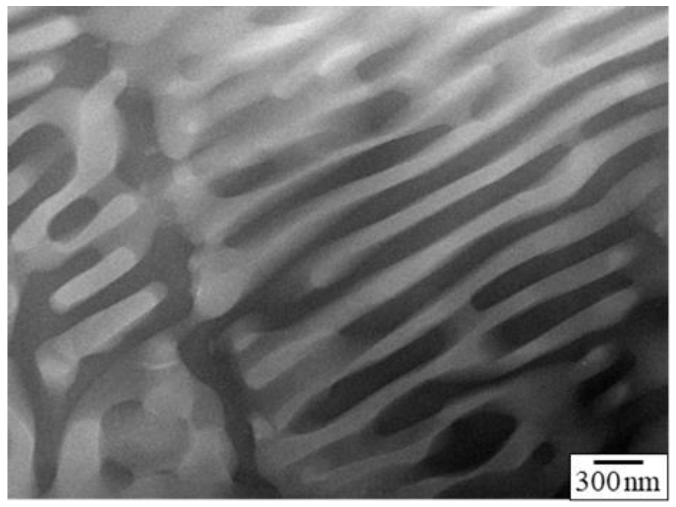
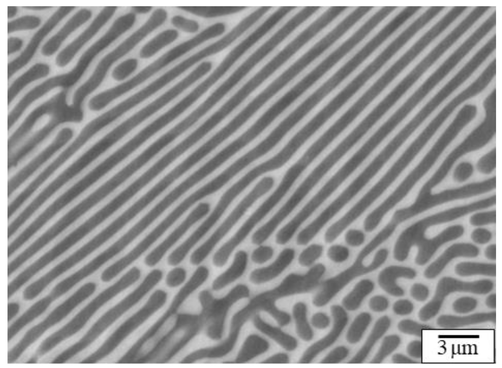
When a Mg–Ca hypoeutectic alloy is melted and then cast into a steel mold, the α/C14 lamellar structure with a spacing of less than 1 μm is obtained, as shown in Figure 1, where each bright α-Mg plate is surrounded by a continuous dark C14–Mg2Ca phase. In a previous work, the temperature region where the α/C14 lamellar structure is stable in morphology was investigated [26]. It was shown that the α/C14 lamellar structure has a stable morphology at temperatures less than 573 K, whereas it becomes gradually coarse in the temperature range above 573 K. A quantitative relationship was identified between the lamellar spacing (λ) and aging time (t): λ2λ02 = kT·t, where λ0 is the α/C14 lamellar spacing for the as-cast specimen and kT is a constant depending on the aging temperature.
The mechanical strength of metallic materials with a lamellar microstructure increases with decreasing λ at ambient temperature [26,27,28,29,30]. In contrast, the effect of λ on the creep strength has not been clarified for magnesium alloys. The objectives of this study were to elucidate the following three points by using a Mg–Ca alloy with a α/C14 fine lamellar microstructure: first, to clarify the orientation relationship between α-Mg and C14–Mg2Ca lamellae through a detailed HRTEM observation; second, to quantitatively clarify the interrelation between creep strength and λ, where λ was controlled by aging at 673 K; and third, to clarify the role of the lamellar interface on dislocation gliding, through the observation of dislocation substructure of the creep specimens.

2. Experimental Section

A binary alloy of composition Mg–13.8 mass% Ca was cast at Mitsui Mining & Smelting Co. (Ageo, Japan), using easily available starting materials of the highest purity. The calcium content was reduced by 2.4 mass% from the eutectic composition to avoid precipitation of the brittle primary C14–Mg2Ca phase. A sample (block dimensions 100 mm × 160 mm × 20 mm) was gravity-cast by the permanent mold casting method under an argon atmosphere at 1053 K. The casting was ejected from the mold and cooled in ambient air until it could be handled. The as-cast specimen revealed that the microstructure was sufficiently homogeneous, and characterized by a mixed microstructure of primary α-Mg phase and α-Mg/C14–Mg2Ca eutectic lamellae. From the binary phase diagram of the Mg–Ca system [6], the weight ratios of the primary α-Mg phase and α/C14 lamellar were estimated as 16% and 84%, according to the lever rule. As the alloy consisted mostly of the α/C14 lamellar structure, this alloy is hereafter referred to as the α-Mg/C14–Mg2Ca eutectic alloy; the microstructure was observed exclusively in the α/C14 lamellar region.
Flat specimens (with gage dimensions of 6 mm × 3 mm × 28 mm) for creep tests were prepared from the casting [31,32]. The creep specimens were subjected to aging treatment at 673 K for 1.1 × 10⁴ to 3.6 × 10⁵ s (i.e., 3–100 h) to control λ [26]. Creep tests were performed in tension on a constant-load creep machine at 473 K, under a stress of 40 MPa. The applied stress of 40 MPa was below half of the 0.2% proof stress for the alloy at 473 K. The tensile displacement was measured using extensometers attached to ridges at both ends of the gauge portion, and the displacement of the extensometer heads was continuously recorded as a function of time using linear variable differential transformers.
The microstructures of the as-cast and crept samples were studied using field-emission scanning electron microscopy (FE-SEM), transmission electron microscopy (TEM), and high-resolution transmission electron microscopy (HRTEM). The specimens mounted in the resin for the FE-SEM observation were polished mechanically with emery paper and alumina slurry, and then etched in a solution of 2 vol% HNO3 and 98 vol% ethyl alcohol for 2 s. For the TEM and HRTEM observations, thin foils were cut from the sample and machined to discs 3 mm in diameter. After mechanical grinding down to approximately 90 μm, the discs were further thinned by dimple-grinding and ion-milling to perforate the center portion of the discs. The perforated discs were examined using TEM (JEOL JEM-2010) and HRTEM (FEI Titan3 G2 60-300), operating at 200 kV and 300 kV, respectively.

3. Results and Discussion

3.1. Initial Microstructure

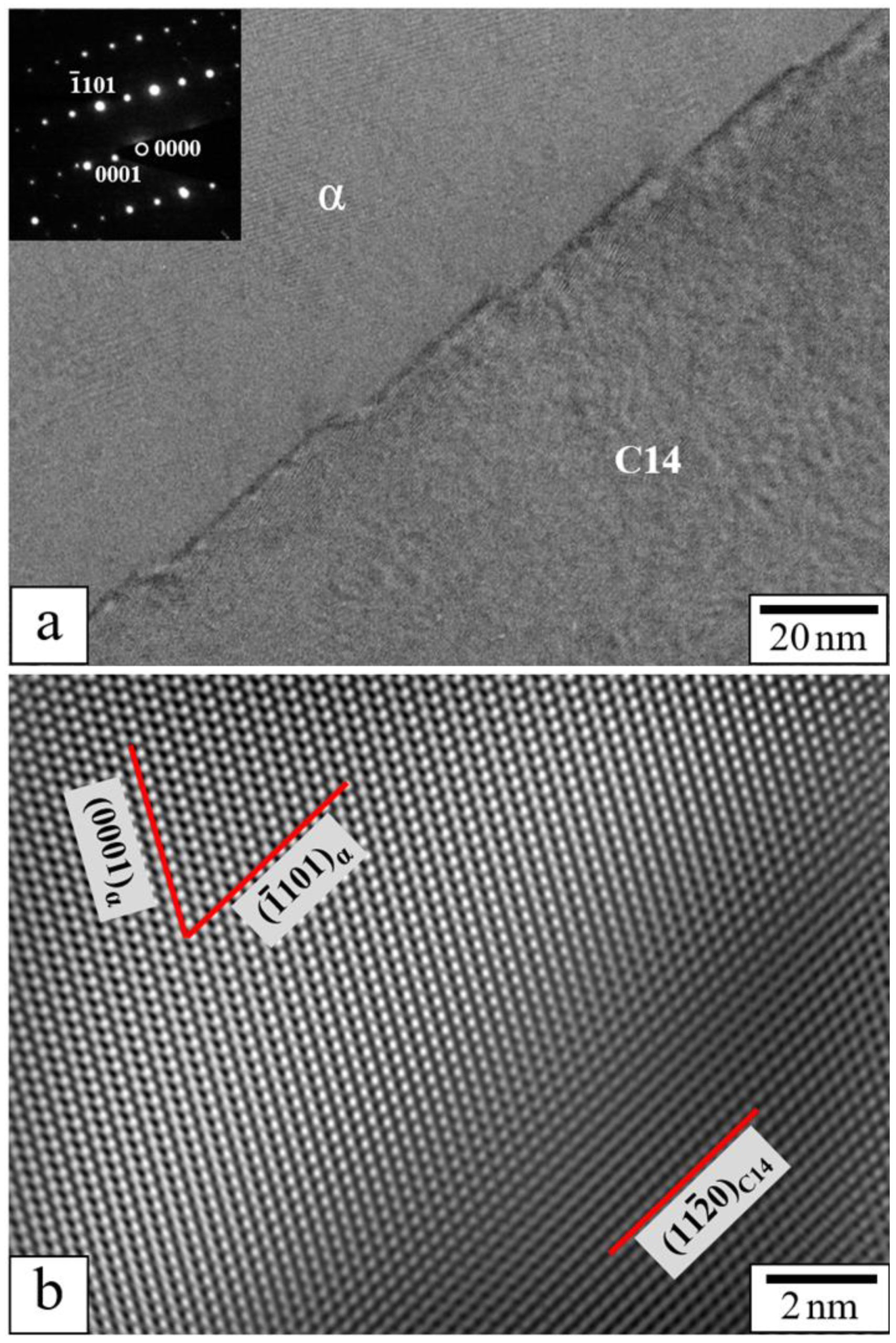
Figure 2 shows a STEM HAADF image of the α/C14 lamellar region in the as-cast α-Mg/C14–Mg2Ca eutectic alloy, where the dark phase is α-Mg and the bright phase is C14–Mg2Ca. The C14–Mg2Ca phase has a plate-like dendritic morphology, and the distance between the centers of the C14 lamellae is approximately 250 nm. The magnified view of the α/C14 interface, which was shown in the previous paper [26], is reproduced in Figure 3. Figure 3a shows a magnified HRTEM image of the region, in which the α/C14 interface is viewed edge-on, along with the selected-area diffraction pattern of the α-Mg lamellae. At high magnification, terraces approximately 30 nm in length and steps approximately 3 nm in height can be seen to alternate along the interface, even if the interface appears smooth at low magnification. Figure 3b shows the STEM HAADF image of a terrace along the α/C14 lamellar interface. The terrace is parallel to the (1101)α pyramidal plane of the α-Mg lamellae and to the (1120)C14 columnar plane of the C14–Mg2Ca lamellae. In addition, the interface appears to be coherent, and the (0001)α basal plane in the α-Mg lamellae is oriented toward the α/C14 interface.

3.2. Creep Properties

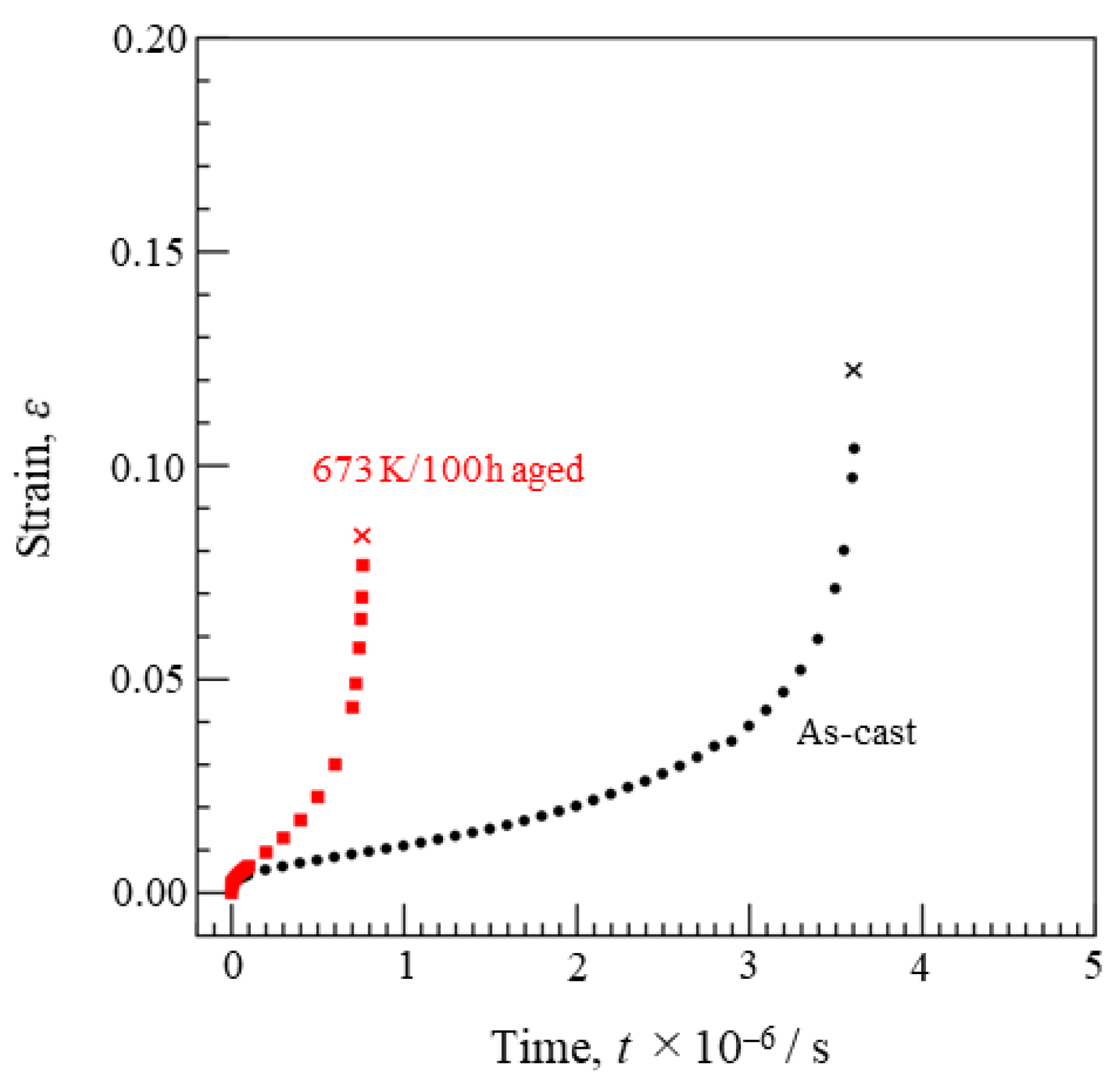
Figure 4 shows the creep curve of the α-Mg/C14–Mg2Ca eutectic alloy aged at 673 K for 100 h, along with the data for the as-cast specimen. Notably, the λ value of the as-cast specimen is 0.9 μm, while that of the specimen aged at 673 K for 100 h is 5.3 μm. After the stress is applied, a normal transient creep is detected in both specimens. Subsequently, there is a gradual increase in the creep rate in the accelerating region, leading to creep rupture. The rupture elongation values of the as-cast specimen and aged specimen (673 K/100 h) are 12.2% and 8.3%, respectively.
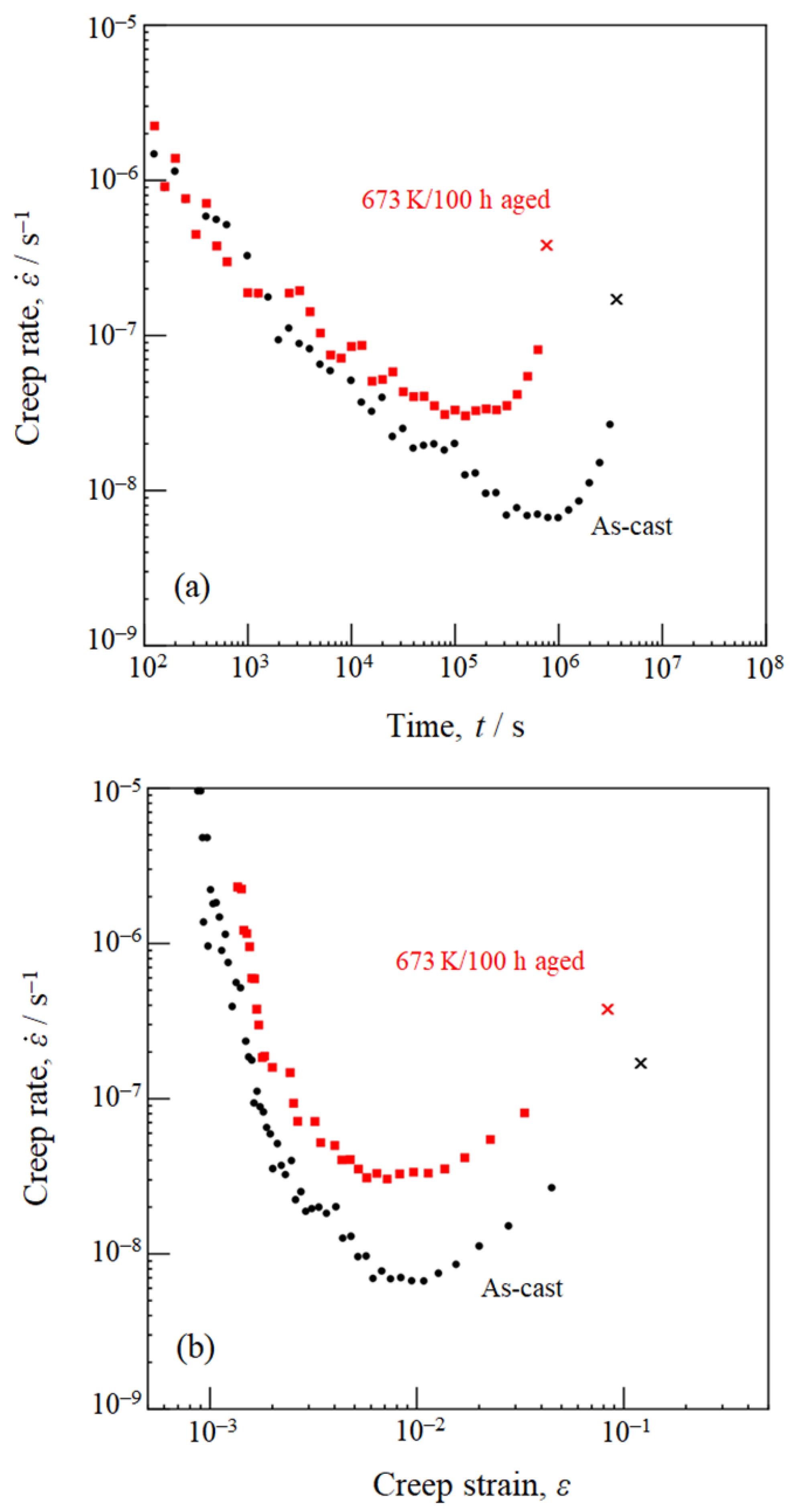
By differentiating the creep strain with respect to time, the creep rate is obtained. Figure 5 shows the creep rate–time curves (Figure 5a) and creep rate–strain curves (Figure 5b) in double logarithmic coordinates. In Figure 5a, the creep rate–time curve of each specimen shows a downward curvature from stress application until creep rupture; a well-defined steady state creep region is hardly evident. For the as-cast specimen, the creep rate decreases by more than two orders of magnitude in the transient region, and the minimum creep rate is observed at a creep time of 8.0 × 10⁵ s; subsequently, creep rupture occurs at 3.6 × 10⁶ s. The creep rate–time curve of the aged specimen (673 K/100 h) is similar to that of the as-cast specimen; the minimum creep rate is higher, and the decrease in the creep rate during the transient stage becomes less significant. Figure 5b shows that the minimum creep rate is identified at a strain of approximately 1% in both specimens. The creep rate–time curves and creep rate–strain curves illustrate the validity of the ϕ-model, even for the α-Mg/C14–Mg2Ca eutectic alloy with a fairly complex microstructure [33].
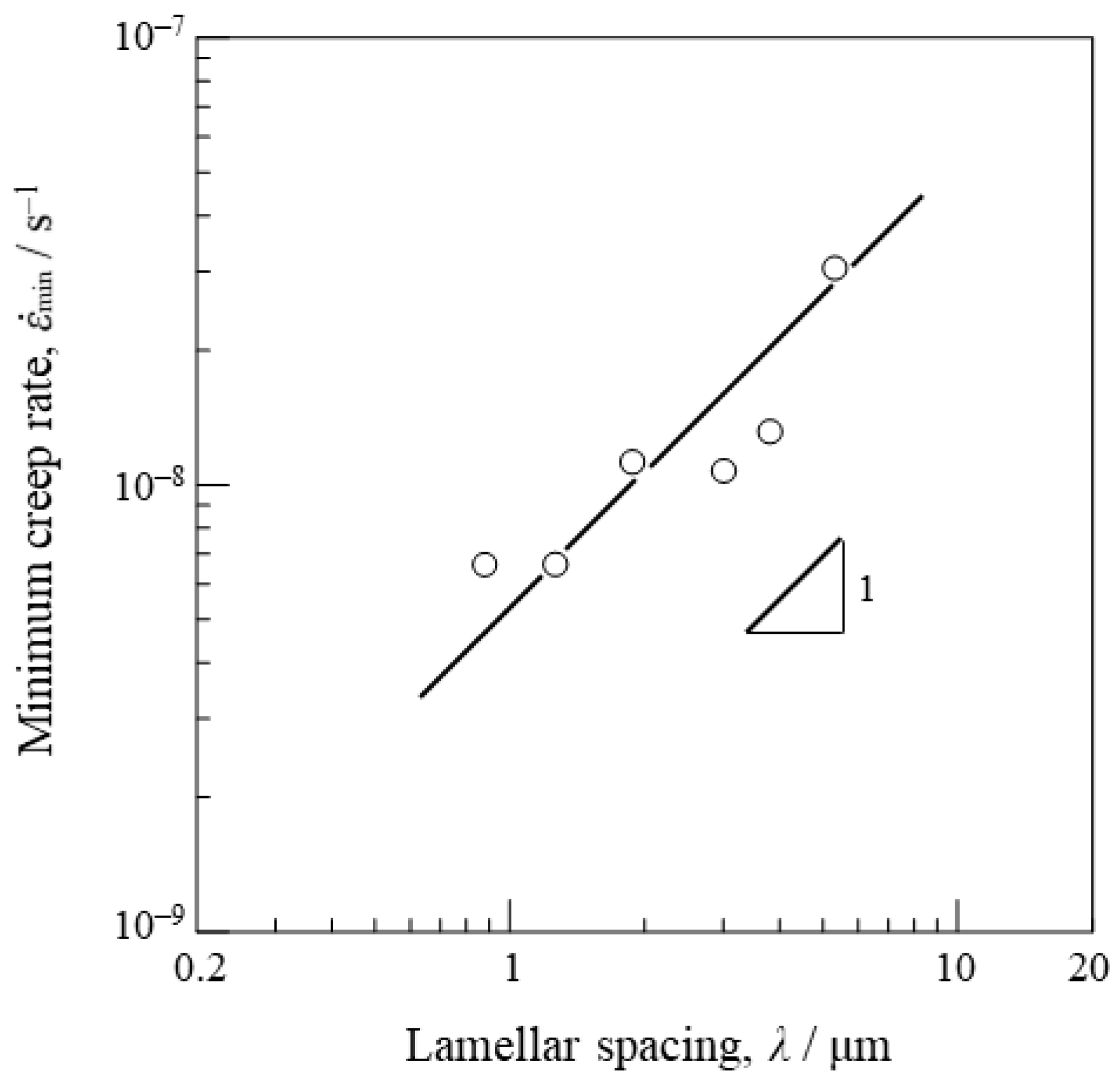
Table 1 presents a summary of the minimum creep rate ( ε ˙ min), rupture life (trup), rupture elongation (εrup), and λ of the α-Mg/C14–Mg2Ca eutectic alloys. In Figure 6, the ε ˙ min of the α-Mg/C14–Mg2Ca eutectic alloy, creep-tested at 473 K under a stress of 40 MPa, is plotted as a function of λ. In Figure 6, ε ˙ min continuously increases with increasing λ, and all six data are located on the line with a slope of unity. Since ε ˙ min decreases continuously with decreasing λ, it is deduced that the α-Mg/C14–Mg2Ca interface improves the creep strength; that is to say, the α-Mg/C14–Mg2Ca interface acts as a creep strengthener. The interface introduction into the microstructure, by employing the eutectic reaction, can be an effective way of improving the creep strength of Mg alloys. It has been suggested that the interface enhances the yield strength at room temperature for metallic multilayers [34]. In this paper, the effectiveness of interface to enhance high-temperature creep strength was experimentally demonstrated for Mg alloys.
The microstructure parameters, such as the colony size (d) and λ, in addition to the creep testing temperature (T) and applied stress (σ), should be included in the phenomenological creep equation for the α-Mg/C14–Mg2Ca eutectic alloy [35,36]. The ε ˙ min of this alloy is expressed as a function of σ, T, d, and λ, as shown in Equation (1):
ε ˙ min   =   A   ( σ / G ) n   ( b / d ) m   ( λ / b ) p   exp   ( Q c / RT ) .
where A is the material constant; G is the shear modulus; b is the length of the Burgers vector in the α-Mg lamellae; R is the gas constant; Qc is the activation energy for creep; and n, m, and p are constants. The slope of the ε ˙ minλ curve in Figure 6 corresponds to p in Equation (1), and the results in Figure 6 suggest p = 1 for the α-Mg/C14–Mg2Ca eutectic alloy. Rupture life (trup) and rupture strain (εrup) are plotted against λ in Figure 7a,b, respectively. Figure 7a shows that trup remains unchanged at approximately 4.0 × 10⁶ s when λ < 3.0 μm, while trup abruptly decreases with increasing λ when λ > 3.0 μm, and the trup value becomes 7.6 × 10⁵ s at λ = 5.3 μm. In Figure 7b, εrup is maximum at 20.6% when λ = 1.9 μm, and decreases when λ is changed from the value of 1.9 μm. A plastic deformation occurs even in the α-Mg/C14–Mg2Ca eutectic alloy, with a fine lamellar microstructure at 473 K.

3.3. Dislocation Analysis

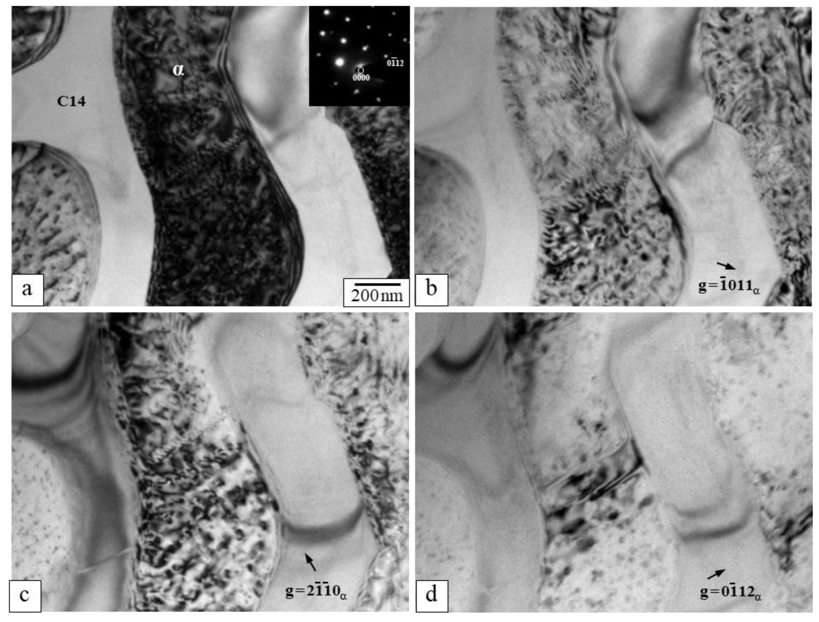
The dislocation substructure of the as-cast α-Mg/C14–Mg2Ca eutectic alloy that underwent creep at 473 K under a stress of 40 MPa was investigated to clarify the role of the α/C14 interface in dislocation-gliding during creep. Figure 8 shows the SEM BEI of the creep-ruptured specimen, where the dark phase is α-Mg and the bright phase is C14–Mg2Ca. The fine lamellar structure is maintained, and the α/C14 interface remains smooth even after the high-temperature creep exposure at 473 K for 1006 h. Figure 9a shows the HRTEM image of the creep-ruptured specimen taken with B = [0111]α for the α-Mg lamellae. Many dislocations are distributed within the α-Mg lamellae, while dislocations are hardly detected within the C14–Mg2Ca lamellae.
The g·b values with an incident beam direction B = [0111]α are calculated for reciprocal lattice vectors g = 1011α, 2110α and 0112α, as listed in Table 2, to identify whether perfect <a>, <a+c>, and <c> dislocations are visible in the hcp structure with the Burgers vector (b). Under the two-beam condition g = 1011α, <a> dislocations with b = 1/3[1120] and b = 1/3[2110], 4/6 of <a+c> dislocations, and <c> dislocations are visible, while <a> dislocations with b = 1/3[1210] and 2/6 of <a+c> dislocations are invisible. In the case of g = 2110α, <a> dislocations and <a+c> dislocations are visible, while <c> dislocations are invisible. Further, <a> dislocations with b = 1/3[1120] and b = 1/3[1210], <a+c> dislocations, and <c> dislocations are visible, whereas <a> dislocations with b = 1/3[2110] are invisible when g = 0112α.
Figure 9b–d shows the HRTEM images of the same field as shown in Figure 9a, captured under the two-beam diffraction condition with g = 1011α (Figure 9b), g = 2110α (Figure 9c), and g = 0112α (Figure 9d), respectively. It is noted that Figure 9a,d, which is shown in the previous paper [37], is reproduced. The visible dislocations within the α-Mg lamellae under the multiple-beam diffraction condition shown in Figure 9a are almost detected in Figure 9b,c, while they are scarcely observed under the two-beam diffraction condition g = 0112α (Figure 9d). This result indicates that most dislocations in the α-Mg lamellae during creep for the α-Mg/C14–Mg2Ca eutectic alloy are <a> dislocations with an identical Burgers vector of b = 1/3[2110].
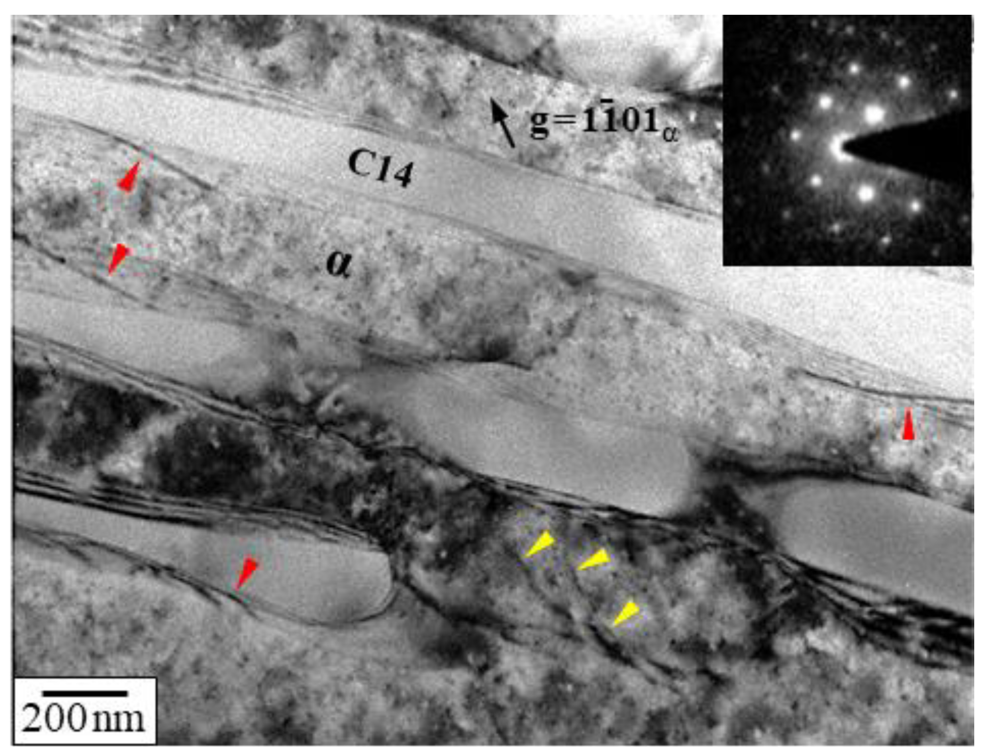
Figure 10 shows the TEM BFI of the creep-ruptured specimen, in which the region with a low density of dislocations is chosen for the observation. Dislocations are detected at the α/C14 interface, as indicated by red arrowheads, and they are not arranged in any specific manner but isolated or randomly distributed. In addition, dislocations are emitted from the end of the C14 lamellae into α-Mg lamellae, as indicated by yellow arrowheads. From the results, it is inferred that the α/C14 interface is a barrier to the gliding of <a> dislocations during creep, and limits the dislocations within the α-Mg lamellae. It is noted that the transfer of plasticity across the Mg/Mg2Ca interface has been explored in detail at room temperature for a dual-phase magnesium alloy [38]. The dislocation movements during creep deformation for the α-Mg/C14–Mg2Ca eutectic alloy are summarized as follows: (i) dislocations, most of which are <a> type, are introduced within the α-Mg lamellae; (ii) the <a> dislocations glide on the (0001)α basal plane in the α-Mg lamellae and meet the α/C14 interface; (iii) the dislocations move on the α/C14 interface by climbing to the end of the C14–Mg2Ca lamellae; (iv) the dislocations are emitted into the α-Mg lamellae due to the stress concentration driven by the following dislocations at the α/C14 interface.
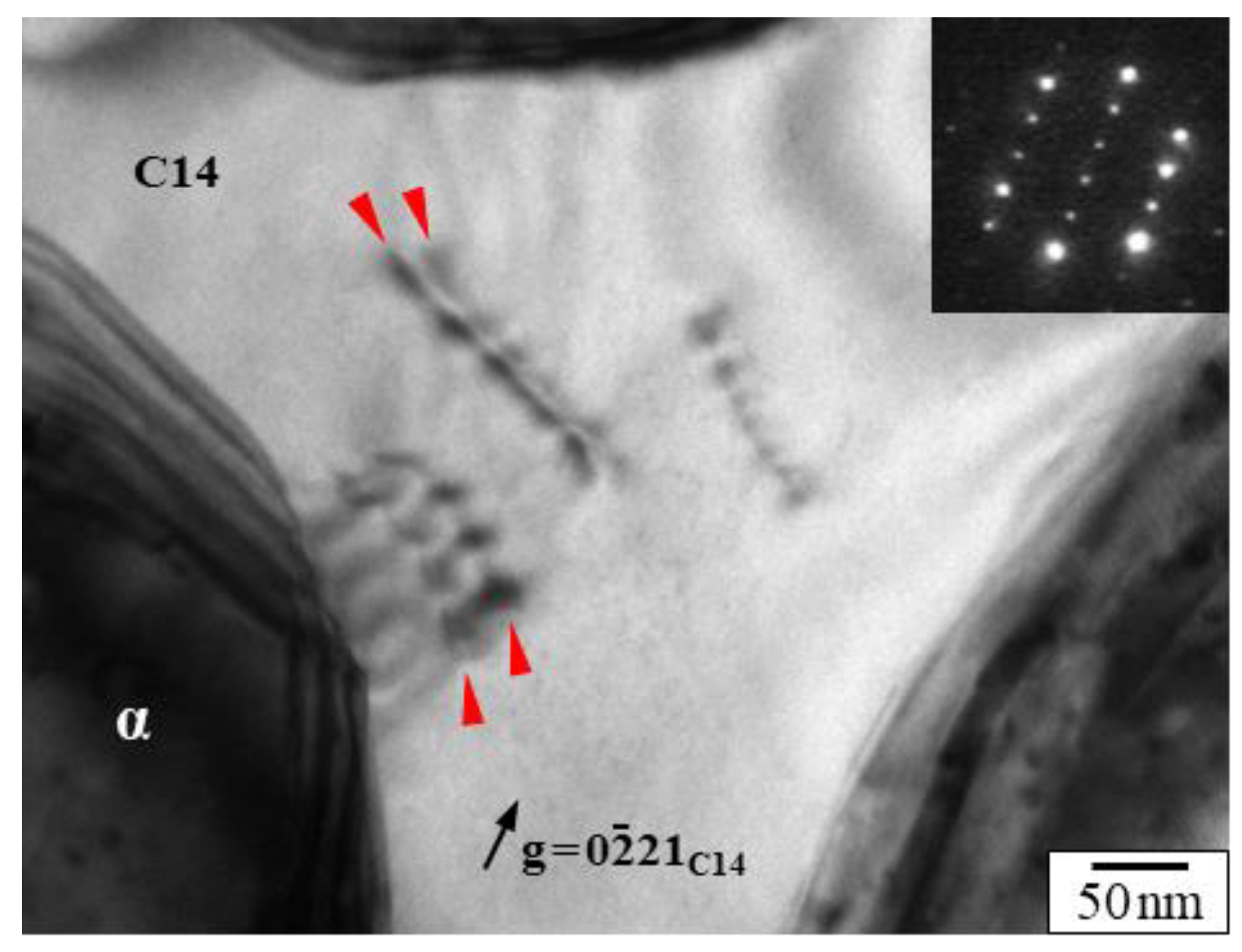
Figure 11 shows the TEM BFI of the creep-interrupted specimen, taken with B = [1216]C14 and g = 0221C14. Some dislocations are observed at the junction of the C14–Mg2Ca lamellae, though this is a rare event. Notably, the dissociation of the dislocations can be clearly seen, as indicated by red arrowheads, and the width between the divorced dislocations ranges from 10 to 20 nm. The dissociation reaction from a perfect dislocation to two partial dislocations in the C14–Mg2Ca lamellae is considered as scheme (2) [39].
1 / 3 [ 11 2 - 0 ] = 1 / 3 [ 10 1 - 0 ] + SF ( 0001 ) + 1 / 3 [ 01 1 - 0 ]
Evidently, plastic deformation occurs even in the hard C14–Mg2Ca lamellar during creep for the α-Mg/C14–Mg2Ca eutectic alloy.
In conclusion, the α/C14 interface enhances the creep strength for the α-Mg/C14–Mg2Ca eutectic alloy. The interface introduction into the microstructure by employing the eutectic reaction can be an effective way of improving the high-temperature creep strength. The interface strengthening is applicable to eutectic alloys based on refractory metals to develop advanced high-temperature materials beyond superalloys. In the future, the applicability of interface strengthening to intermetallic–intermetallic eutectic alloys, not only to metallic–intermetallic eutectic alloys, should be clarified.

4. Conclusions

A α-Mg/C14–Mg2Ca eutectic alloy with a nearly full lamellar structure, whose lamellar spacing was controlled by aging treatment at 673 K, was subjected to creep-testing at 473 K under a stress of 40 MPa to evaluate the effect of the α/C14 interface on creep strength. In addition, the dislocation substructure of the crept specimen was investigated using TEM and HRTEM. The following results were obtained:
  • The α/C14 interface is composed of terraces and steps, with terraces parallel to the (1101)α pyramidal plane of the α-Mg lamellae and to the (1120)C14 columnar plane of the C14–Mg2Ca lamellae.
  • The alloy shows three stages of creep: a normal transient creep stage, a minimum creep rate stage, and an accelerating stage. A well-defined steady state is barely evident. Since the minimum creep rate decreases continuously with decreasing lamellar spacing, the α-Mg/C14–Mg2Ca interface is considered to enhance the creep strength; that is to say, the α-Mg/C14–Mg2Ca interface acts as a creep-strengthener.
  • Dislocations are mainly introduced within the soft α-Mg lamellae during creep, and most of them are <a> dislocations with identical Burgers vectors. The dislocations are not arranged, but randomly distributed at the α/C14 interface. Dislocations are rarely introduced in the hard C14–Mg2Ca lamellae, and the dissociation reaction from a perfect dislocation to two partial dislocations is detected in the C14–Mg2Ca lamellae.

Author Contributions

Conceptualization, Y.T.; investigation, S.A. and K.O.; writing—original draft preparation, S.A. and K.O.; writing—review and editing, S.A. and Y.T.; supervision, Y.T.; funding acquisition, Y.T. All authors have read and agreed to the published version of the manuscript.

Funding

This research was supported by a Grant-in-Aid for Scientific Research C (19K05054) of JSPS, Japan. Y.T. greatly appreciates the support of the Light Metal Educational Foundation, Japan.

Data Availability Statement

Data presented in this article are available upon request from the corresponding author.

Acknowledgments

The authors would like to thank Susumu Onaka and Yoshisato Kimura of Tokyo Institute of Technology, and Kenji Ohkubo and Ryo Ota of Hokkaido University for their kind assistance with the microstructure observation using electron microscopy. A part of this work was conducted at Hokkaido University, supported by the Nanotechnology Platform Program of the Ministry of Education, Culture, Sports, Science and Technology (MEXT), Japan.

Conflicts of Interest

The authors declare no conflict of interest.

References

  1. Agnew, S.R.; Nie, J.F. Preface to the viewpoint set on: The current state of magnesium alloy science and technology. Scr. Mater. 2010, 63, 671–673. [Google Scholar] [CrossRef]
  2. Luo, A.A. Recent magnesium alloy development for elevated temperature applications. Int. Mater. Rev. 2004, 49, 13–30. [Google Scholar] [CrossRef]
  3. Zhu, S.M.; Mordike, B.L.; Nie, J.F. Creep properties of a Mg–Al–Ca alloy produced by different casting technologies. Mater. Sci. Eng. A 2008, 483–484, 583–586. [Google Scholar] [CrossRef]
  4. Vagarali, S.S.; Langdon, T.G. Deformation mechanisms in h.c.p. metals at elevated temperatures—I. Creep behavior of magnesium. Acta Metall. 1981, 29, 1969–1982. [Google Scholar] [CrossRef]
  5. Shi, L.; Northwood, D.O. Strain-hardening and recovery during the creep of pure polycrystalline magnesium. Acta Metall. Mater. 1994, 42, 871–877. [Google Scholar] [CrossRef]
  6. Massalski, T.B. Binary Alloy Phase Diagrams, 2nd ed.; ASM International: Materials Park, OH, USA, 1990. [Google Scholar]
  7. Luo, A.A.; Balogh, M.P.; Powell, B.R. Creep and microstructure of magnesium–aluminum–calcium based alloys. Metall. Mater. Trans. A 2002, 33, 567–574. [Google Scholar] [CrossRef]
  8. Terada, Y.; Ishimatsu, N.; Sato, T. Creep parameters in a die-cast Mg–Al–Ca alloy. Mater. Trans. 2007, 48, 2329–2335. [Google Scholar] [CrossRef] [Green Version]
  9. Suzuki, A.; Saddock, N.D.; TerBush, J.R.; Powell, B.R.; Jones, J.W.; Pollock, T.M. Precipitation strengthening of a Mg–Al–Ca-based AXJ530 die-cast alloy. Metall. Mater. Trans. A 2008, 39, 696–702. [Google Scholar] [CrossRef]
  10. Nie, J.-F. Precipitation and hardening in magnesium alloys. Metall. Mater. Trans. A 2012, 43, 3891–3939. [Google Scholar] [CrossRef] [Green Version]
  11. Hort, N.; Huang, Y.; Kainer, K.U. Intermetallics in magnesium alloys. Adv. Eng. Mater. 2006, 8, 235–240. [Google Scholar] [CrossRef]
  12. Pollock, T.M. Weight loss with magnesium alloys. Science 2010, 328, 986–987. [Google Scholar] [CrossRef]
  13. Misra, A.; Gibala, R. Plasticity in multiphase intermetallics. Intermetallics 2000, 8, 1025–1034. [Google Scholar] [CrossRef]
  14. Milenkovic, S.; Palm, M. Microstructure and mechanical properties of directionally solidified Fe–Al–Nb eutectic. Intermetallics 2008, 16, 1212–1218. [Google Scholar] [CrossRef]
  15. Perepezko, J.H. The hotter the engine, the better. Science 2009, 326, 1068–1069. [Google Scholar] [CrossRef]
  16. Takata, N.; Okano, T.; Suzuki, A.; Kobashi, M. Microstructure of intermetallic-reinforced Al-based alloy composites fabricated using eutectic reactions in Al–Mg–Zn ternary system. Intermetallics 2018, 95, 48–58. [Google Scholar] [CrossRef]
  17. Suzuki, A.; Saddock, N.D.; Jones, J.W.; Pollock, T.M. Phase equilibria in the Mg–Al–Ca ternary system at 773 and 673 K. Metall. Mater. Trans. A 2006, 37, 975–983. [Google Scholar] [CrossRef]
  18. Luo, A.A.; Powell, B.R.; Sachdev, A.K. Computational phase equilibria and experimental investigation of magnesium–aluminum–calcium alloys. Intermetallics 2012, 24, 22–29. [Google Scholar] [CrossRef]
  19. Terada, Y.; Itoh, D.; Sato, T. Dislocation analysis of die-cast Mg–Al–Ca alloy after creep deformation. Mater. Sci. Eng. A 2009, 523, 214–219. [Google Scholar] [CrossRef]
  20. Terada, Y.; Murata, Y.; Sato, T. Life assessment of die-cast Mg–5Al–1.7Ca alloys under creep service conditions. Mater. Sci. Eng. A 2014, 613, 136–140. [Google Scholar] [CrossRef]
  21. Kashiwase, S.; Unekawa, M.; Hisazawa, H.; Terada, Y. Three-dimensional morphology of C15–Al2Ca precipitates in a Mg–Al–Ca alloy. Mater. Trans. 2019, 60, 2048–2052. [Google Scholar] [CrossRef]
  22. Kashiwase, S.; Unekawa, M.; Hisazawa, H.; Terada, Y. C15–Al2Ca precipitation in a Mg–Al–Ca alloy. Mater. Trans. 2020, 61, 375–380. [Google Scholar] [CrossRef]
  23. Suzuki, A.; Saddock, N.D.; Jones, N.D.; Pollock, T.M. Solidification paths and eutectic intermetallic phases in Mg–Al–Ca ternary alloys. Acta Mater. 2005, 53, 2823–2834. [Google Scholar] [CrossRef]
  24. Xu, S.W.; Oh-ishi, K.; Kamado, S.; Takahashi, H.; Homma, T. Effects of different cooling rates during two casting processes on the microstructures and mechanical properties of extruded Mg–Al–Ca–Mn alloy. Mater. Sci. Eng. A 2012, 542, 71–78. [Google Scholar] [CrossRef]
  25. Zubair, M.; Sandlöbes, S.; Wollenweber, M.A.; Kusche, C.F.; Hildebrandt, W.; Broeckmann, C.; Korte-Kerzel, S. On the role of Laves phases on the mechanical properties of Mg–Al–Ca alloys. Mater. Sci. Eng. A 2019, 756, 272–283. [Google Scholar] [CrossRef]
  26. Abe, S.; Oishi, K.; Terada, Y. Lamellar structure stability of a two-phase α-Mg/C14–Mg2Ca alloy. Mater. Trans. 2021, 62, 544–550. [Google Scholar] [CrossRef]
  27. Ray, K.K.; Mondal, D. The effect of interlamellar spacing on strength of pearlite in annealed eutectoid and hypoeutectoid plain carbon steels. Acta Metall. Mater. 1991, 39, 2201–2208. [Google Scholar] [CrossRef]
  28. Maziasz, P.J.; Liu, C.T. Development of ultrafine lamellar structures in two-phase γ-TiAl alloys. Metall. Mater. Trans. A 1998, 29, 105–117. [Google Scholar] [CrossRef]
  29. Baker, I.; Meng, F. Lamellar coarsening in Fe28Ni18Mn33Al21 and its influence on room temperature tensile behavior. Acta Mater. 2015, 95, 124–131. [Google Scholar] [CrossRef] [Green Version]
  30. Lei, Q.; Ramakrishnan, B.P.; Wang, S.; Wang, Y.; Mazumder, J.; Misra, A. Structural refinement and nanomechanical response of laser remelted Al–Al2Cu lamellar eutectic. Mater. Sci. Eng. A 2017, 706, 115–125. [Google Scholar] [CrossRef]
  31. Ishimatsu, N.; Terada, Y.; Sato, T.; Ohori, K. Creep characteristics of a diecast AM50 magnesium alloy. Metall. Mater. Trans. A 2006, 37, 243–248. [Google Scholar] [CrossRef]
  32. Terada, Y.; Enokida, T.; Sato, T. Effect of prior deformation on creep behavior of a die-cast Mg–Al–Ca alloy. Mater. Trans. 2009, 50, 2351–2354. [Google Scholar] [CrossRef]
  33. Sandström, R. Basic model for primary and secondary creep in copper. Acta Mater. 2012, 60, 314–322. [Google Scholar] [CrossRef]
  34. Li, Y.P.; Zhang, G.P.; Wang, W.; Tan, J.; Zhu, S.J. On interface strengthening ability in metallic multilayers. Scr. Mater. 2007, 57, 117–120. [Google Scholar] [CrossRef]
  35. Cadek, J. Creep in Metallic Materials; Elsevier: Amsterdam, The Netherlands, 1988. [Google Scholar]
  36. Kassner, M.E.; Perez-Prado, M.T. Fundamentals of Creep in Metals and Alloys; Elsevier: Amsterdam, The Netherlands, 2004. [Google Scholar]
  37. Oishi, K.; Araki, S.; Terada, Y. Effect of lamellar spacing on creep strength of α-Mg/C14–Mg2Ca eutectic alloy. Mater. Trans. 2021, 62, 1414–1419. [Google Scholar] [CrossRef]
  38. Guénolé, J.; Zubair, M.; Roy, S.; Xie, Z.; Lipińska-Chwałek, M.; Sandlöbes-Haut, S.; Korte-Kerzel, S. Exploring the transfer of plasticity across Laves phase interfaces in a dual phase magnesium alloy. Mater. Des. 2021, 202, 109572. [Google Scholar] [CrossRef]
  39. Zehnder, C.; Czerwinski, K.; Molodov, K.D.; Sandlöbes-Haut, S.; Gibson, J.S.K.-L.; Korte-Kerzel, S. Plastic deformation of single crystalline C14 Mg2Ca Laves phase at room temperature. Mater. Sci. Eng. A 2019, 759, 754–761. [Google Scholar] [CrossRef]
Figure 1. SEM SEI of α/C14 lamellar structure for the as-cast α-Mg/C14–Mg2Ca eutectic alloy. In the lamellar microstructure, each α-Mg plate (bright contrast) is surrounded by a continuous C14–Mg2Ca phase (dark contrast).
Metals 11 01913 g001
Figure 2. STEM HAADF image of α/C14 lamellar structure for the as-cast α-Mg/C14–Mg2Ca eutectic alloy. The dark phase is α-Mg, while the bright phase is C14–Mg2Ca.
Metals 11 01913 g002
Figure 3. HRTEM image of the α/C14 interface, taken with B = [1120]α, for the as-cast α-Mg/C14–Mg2Ca eutectic alloy (a), in which terraces and steps alternate along the interface. STEM HAADF image of a terrace is shown in (b). Reproduced with permission from [26].
Metals 11 01913 g003
Figure 4. Strain vs. time at 473 K under a stress of 40 MPa for the α-Mg/C14–Mg2Ca eutectic alloy aged at 673 K for 100 h, together with that for the as-cast specimen.
Metals 11 01913 g004
Figure 5. Creep rate vs. time (a) and creep rate vs. strain (b) in a log–log diagram at 473 K under a stress of 40 MPa for the α-Mg/C14–Mg2Ca eutectic alloy aged at 673 K for 100 h, together with that for the as-cast specimen.
Metals 11 01913 g005
Figure 6. Plots of minimum creep rate vs. lamellar spacing for the α-Mg/C14–Mg2Ca eutectic alloy, where the creep tests were carried out at 473 K under a stress of 40 MPa.
Metals 11 01913 g006
Figure 7. Plots of rupture life vs. lamellar spacing (a) and rupture elongation vs. lamellar spacing (b) for the α-Mg/C14–Mg2Ca eutectic alloy, where the creep tests were carried out at 473 K under a stress of 40 MPa.
Metals 11 01913 g007
Figure 8. SEM BEI of the as-cast α-Mg/C14–Mg2Ca eutectic alloy creep-ruptured at 473 K under a stress of 40 MPa. The dark phase is α-Mg, while the bright phase is C14–Mg2Ca.
Metals 11 01913 g008
Figure 9. HRTEM images, taken with B = [0111]α, of the as-cast α-Mg/C14–Mg2Ca eutectic alloy creep-ruptured at 473 K under a stress of 40 MPa, under multiple (a) and two-beam diffraction conditions (bd). Reproduced with permission from [37].
Metals 11 01913 g009
Figure 10. TEM BFI, taken with B = [1213]α and g = 1101α, of the as-cast α-Mg/C14–Mg2Ca eutectic alloy creep-ruptured at 473 K under a stress of 40 MPa. The dislocations placed on the α/C14 interface are indicated by red arrowheads, while those positioned within the α-Mg lamellae are indicated by yellow arrowheads.
Metals 11 01913 g010
Figure 11. TEM BFI, taken with B = [1216]C14 and g = 0221C14, of the as-cast α-Mg/C14–Mg2Ca eutectic alloy creep-ruptured at 473 K under a stress of 40 MPa. Partial dislocations with a width of 10–20 nm indicated by red arrowheads are detected in the C14–Mg2Ca phase.
Metals 11 01913 g011
Table 1. Summary of minimum creep rate ( ε ˙ min), rupture life (trup), and rupture strain (εrup) for the α-Mg/C14–Mg2Ca eutectic alloys, together with the lamellar spacing (λ). The creep tests were conducted at 473 K under a stress of 40 MPa.
Specimenλ (μm) ε ˙ min   ( s 1 ) trup (s)εrup (%)
As-cast0.96.6 × 10–93.6 × 10⁶ (1006 h)12.2
673 K/3 h aged1.36.6 × 10–94.6 × 10⁶ (1283 h)18.0
673 K/10 h aged1.91.1 × 10–83.4 × 10⁶ (947 h)20.6
673 K/30 h aged3.01.1 × 10–83.8 × 10⁶ (1042 h)17.3
673 K/50 h aged3.41.3 × 10–82.5 × 10⁶ (692 h)8.5
673 K/100 h aged5.33.0 × 10–87.6 × 10⁵ (212 h)8.3
Table 2. The g·b invisibility criterion for perfect dislocations in the hexagonal close-packed crystals close to the [0111] zone axis.
Modebg = 101121100112
<a>1/3 [1120]−11−1
1/3 [1210]011
1/3 [2110]1−20
<a+c>1/3 [1123]011
1/3 [1213]113
1/3 [2113]2−22
1/3 [1123]−21−3
1/3 [1213]−11−1
1/3 [2113]0−2−2
<c>[0001]102
Publisher’s Note: MDPI stays neutral with regard to jurisdictional claims in published maps and institutional affiliations.