Article

Design against Fatigue of Super Duplex Stainless Steel Structures Fabricated by Wire Arc Additive Manufacturing Process

School of Mechanical Engineering, The University of Adelaide, Adelaide, SA 5005, Australia
*
Author to whom correspondence should be addressed.
Metals 2021, 11(12), 1965; https://doi.org/10.3390/met11121965
Submission received: 31 October 2021 / Revised: 27 November 2021 / Accepted: 30 November 2021 / Published: 7 December 2021

Abstract

:
Additive manufacturing (AM) is increasingly used to make complex components for a wide spectrum of applications in engineering, medicine and dentistry. Wire arc additive manufacturing (WAAM), as one of AM processes, utilises electric arc and metal wire to fabricate fully dense and heavy metal parts at relatively low costs and high-energy efficiencies. WAAM was successfully applied in the production of several welding-based metal structures. Recently, there was a growing interest in WAAM processing of super duplex stainless steels (SDSS) due to their high strength and excellent corrosion resistance, which make them the prime choice for load-bearing structures in marine applications. Although a number of studies investigated the microstructural and mechanical properties of WAAM-processed SDSS components, little is known regarding their fatigue performance, which is critical in engineering design. This study reports on the outcomes of fatigue tests and fracture surface fractography of WAAM-processed SDSS. The results obtained indicate a significant anisotropy of fatigue properties and fatigue crack initiations resulting from internal defects rather than surface flaws. Based on these experimental results, we suggest an effective design methodology to improve the fatigue life of the WAAM-fabricated SDSS components. We also indicate that post-manufacturing surface treatments should not be underlined for the enhanced fatigue resistance of WAAM-processed SDSS structures.

1. Introduction

Additive manufacturing (AM) is an increasingly popular fabrication method for the layer-by-layer manufacturing of components, using an energy source to melt wire or powder feedstock [1]. The development of AM processes for metal materials has surged over the last two decades because of their numerous advantages over subtractive manufacturing processes, including casting, forging and machining [2]. In particular, AM can drastically reduce material wastage, optimise the material properties, and decrease lead production times to suit component applications [3].
While powder-based AM processes are commonly used for relatively small parts and structures, medium- to large-scale components require different approaches. In recent years, wire arc additive manufacturing (WAAM) emerged as a low-cost alternative to powder-based AM, specifically for the fabrication of medium- to large-scale structures. There are some key advantages for wire-based AM, which include a greater flexibility and control over the fabrication, as well as an easy automotisation of the manufacturing process [4]. Figure 1 shows standard WAAM process equipment, including a robotic arm and positioner table.
There are three main energy sources that can be normally used to deposit wire, which include electron and laser beams, and a plasma arc. The usages of both beams in AM can be more expensive and make the AM processes more complex than plasma arc processing. In particular, wire-arc-based AM is advantageous over beam-based processes, due to its lower capital cost of hardware. Furthermore, gas metal arc (GMA), based WAAM, is a less complicated and more robust process, requiring less maintenance and no expensive tooling, and thus it is our study focus for this paper [4,5].
Driven by cost advantages with significantly reduced lead times, industries such as the aerospace sector, intensely researched and investigated WAAM; specifically, aluminium grade 2319 and titanium alloy grades 5 and 23, more commonly known as Titanium 6V 4Al. Other sectors followed suit, in particular the maritime, petrochemical, desalination, paper, nuclear energy, and oil and gas industries, focusing on high-strength and corrosion-resistant alloys including stainless and duplex steels and nickel alloys [5].
Industry standards and guidelines for AM-related structural design were developed, including WAAM standards for better process and quality control. Particularly, AWS, BSI, ISO and ASTM [6,7,8,9] developed and published specific WAAM guidelines, including acceptable criteria for the sizes and distributions of manufacturing defects, which represent one of the technical challenges associated with welded and AM structures [10]. However, extensive research is yet to be conducted to understand the fatigue properties and effects of WAAM process parameters on these properties. Although there was some dominance of research on the microstructural characterisation and WAAM process modelling, minimum efforts were devoted to the investigation of the fatigue and crack growth behaviour of WAAM-processed materials [11,12,13].
For WAAM-processed materials, fatigue studies predominantly focused on aerospace-grade titanium alloys [14]. Several recent studies also investigated the fatigue properties of steel components. For example, Dirisu et al. [15] studied the effect of cold rolled and machined surface finish on fatigue resistance of ER70 carbon steel parts fabricated by WAAM. The study showed a very slight increase in the fatigue life of machined WAAM specimens in comparison with as-deposited untreated ones. As-deposited rolled specimens yielded a higher ultimate strength, but significantly lower fatigue limits. Further, Duraisamy et al. [16] confirmed the microstructural and mechanical anisotropy of WAAM-fabricated SS347 stainless steels, and concluded that the reduction in internal manufacturing defects could increase the fatigue strength, which is similar to welded structures.
Due to their increasing use in the oil and gas sectors, pulp and paper mills and chemical processing plants, and super duplex stainless steels (SDSS) became the focus of the current investigation. Owing to their ferritic–austenitic microstructures, SDSS possess a higher mechanical strength than standard austenitic steels and a superior corrosion resistance. The materials were originally developed to resist corrosion in seawater; therefore, they are particularly suitable for marine applications [17]. SDSS are two-phase austenitic–ferritic alloys with principal alloying elements of chromium, nickel and molybdenum. Their mechanical properties are often enhanced through nitrogen alloying [18]. Several studies of the fatigue properties of conventionally made duplex steels were performed, concentrating on low cycle fatigue and fatigue crack propagation [19,20]. In the wide interval of fatigue lives, the fatigue life of SDSS with elevated nitrogen content was only reported by Akdut [21]. However, little is known regarding the fatigue properties of SDSS fabricated by WAAM. In particular there is little research focusing on obtaining fatigue limits; the latter represent essential information needed for design against fatigue failures. Stützer et al. [22] reviewed stainless steels including SDSS fabricated by WAAM. They concluded that the fatigue properties of these materials could be very different compared to conventional fabrication methods (casting, forging and machining), and significant work must be conducted to characterise their fatigue resistance. Therefore, this paper aims to investigate the fatigue resistance of WAAM-produced SDSS, its defect morphology, and the features of failure initiations. Our results rationalise some technical solutions to increase the fatigue life of fabricated components.

2. Materials and Methods

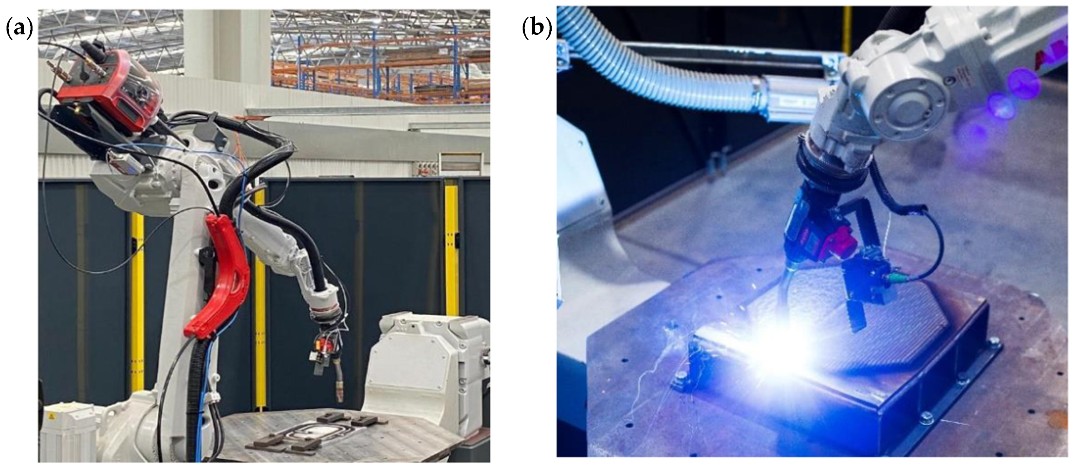
2.1. WAAM Processing

Two ER2594 SDSS test walls with dimensions of 450 mm × 230 mm × 23 mm (Figure 2) were manufactured in WAAM process. The chemical composition of the material is provided in Table 1. Layers were deposited using a standard cold metal transfer (CMT) welding process at 4.8 kg/h, during which the droplet transfer was made in the short circuit mode. The path planning for repeated bead layering was achieved using an integrated ABB robotic system with software WAMSoft® (version 3, Adelaide, Australia), which controlled the accuracy and consistency of welding parameters, the placement of beads and the dwell time between layers. Fronius TransPuls Synergic 500 CMT was used as the welding equipment power source.
Multi-pass bead deposits were made on one side of a super duplex 2507 substrate, which was retrained with clamps, using a 1.2 mm diameter super duplex wire feedstock ER2594 SDSS. A layering strategy, which was 3 beads wide and had a slight oscillation, was employed. Welding was conducted with the torch perpendicular to the work and with an alternating starting point sequence from each end of the test wall length to mitigate any unevenness on the completed height. An argon shielding gas with 20 L/min flow rate was used and measured at the torch nozzle. Two test walls were printed with an optimised dwell time based on a set inter-pass temperature, both with CMT-WAAM process parameters outlined in Table 2. Heat input and cooling rates were chosen from optimised parameter values created from best practice and bead on plate trials, this also determined the dwell time between layers, which was set at 150 °C until the proceeding bead was to be deposited.
Samples were polished and etched in preparation for metallographic examination using standard procedures. A Fischer ferrite scope was used to determine the percentages of ferrite and austenite in the deposited material across the entire height of the test walls. Five reading spots were made across the height of the test walls.
Twenty-five specimens from the two walls (Figure 2) were cut and machined to obtain 13 longitudinally deposited and 12 transversely deposited specimens with the dimensions (Figure 3), which comply with the ASTM E8/E8M-16a standard for tensile testing [23]. All specimens were polished prior to the mechanical testing. A minimum of at least 2 specimens underwent the same load conditions across all specimens in order to find the fatigue limit values and gain consistent data.

2.2. Mechanical Testing

Tensile testing of the longitudinal and transverse specimens was conducted first to evaluate the monotonic stress–strain behaviour at slow strain rates, as well as to evaluate standard mechanical properties using a computer-controlled Instron machine equipped with a 250 kN load cell. After that, fatigue tests were conducted by applying cyclic loading in a sinusoidal manner with a frequency of 10 Hz and a stress ratio of R = 0.1 using the Instron machine. All tests were performed under the strain control conditions at room temperature. After fatigue tests, fracture surfaces were examined using a Leica microscope to assess fracture surfaces and identify defect geometries, failure modes, and fatigue crack initiation sites.

3. Results and Discussion

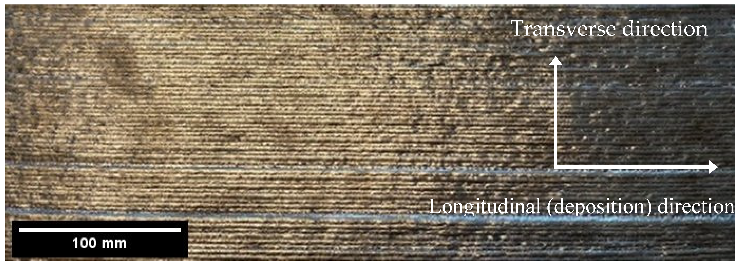
3.1. Microstructure Examination

A phase balance of 50% of both α ferrite and γ austenite is normally expected for an SDSS plate and milled sections. Wire-feedstock-consumable grade ER2594 is normally expected to achieve 40% of α ferrite and 60% of γ austenite for welded joints. Therefore, it should be expected that WAAM deposited ER2594 SDSS has the similar phase balance as welded joints. The phase balance across the WAAM-produced SDSS was consistent with previous literature [13,17,18] and the expected average values of 43% of α ferrite and 57% γ austenite across the entire height of the test walls.

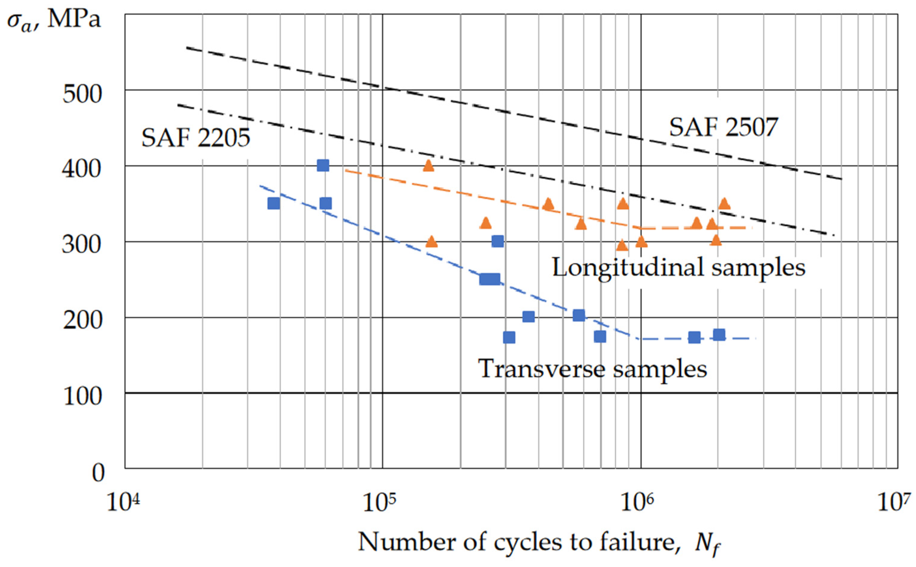
3.2. Mechanical Testing
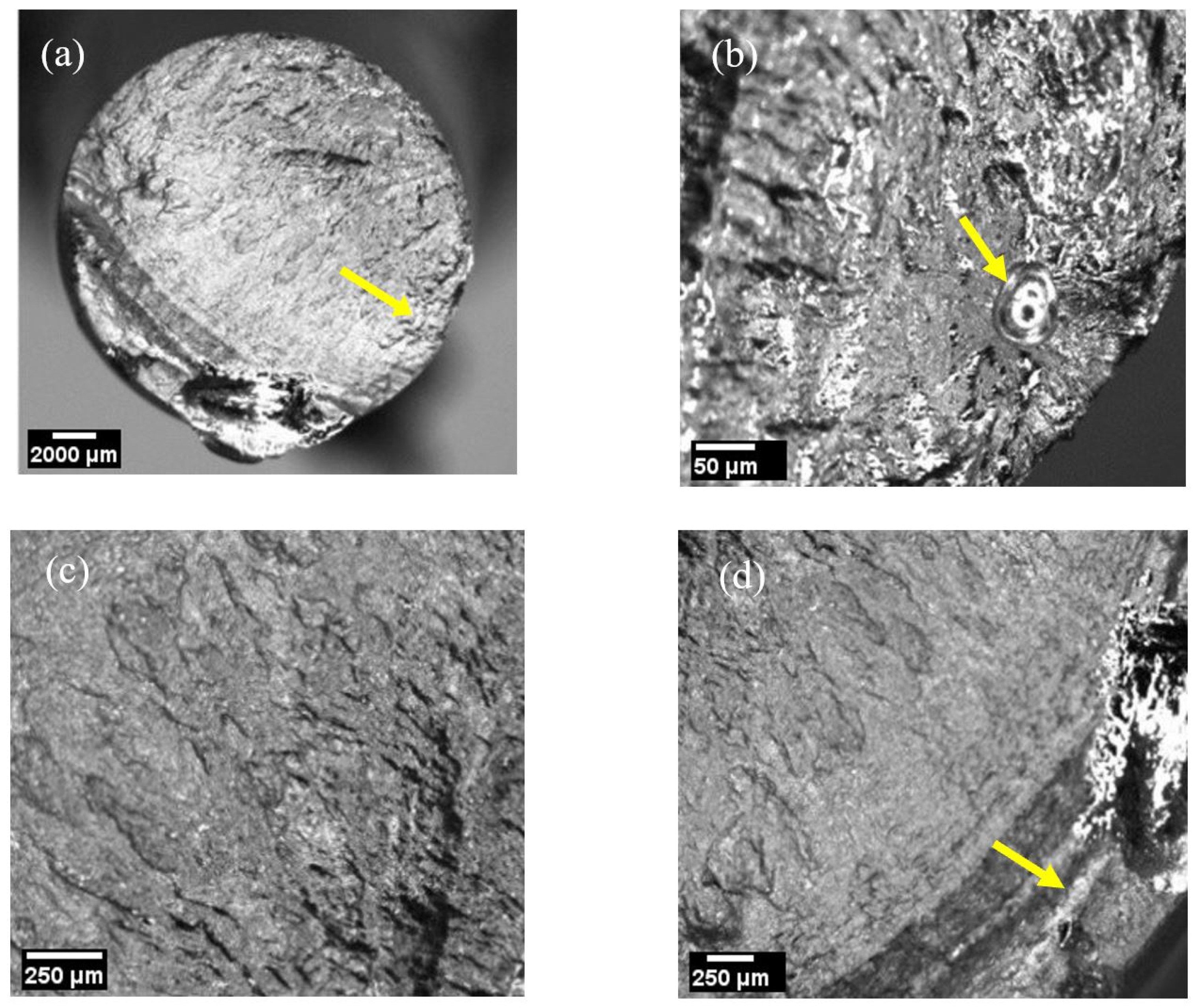
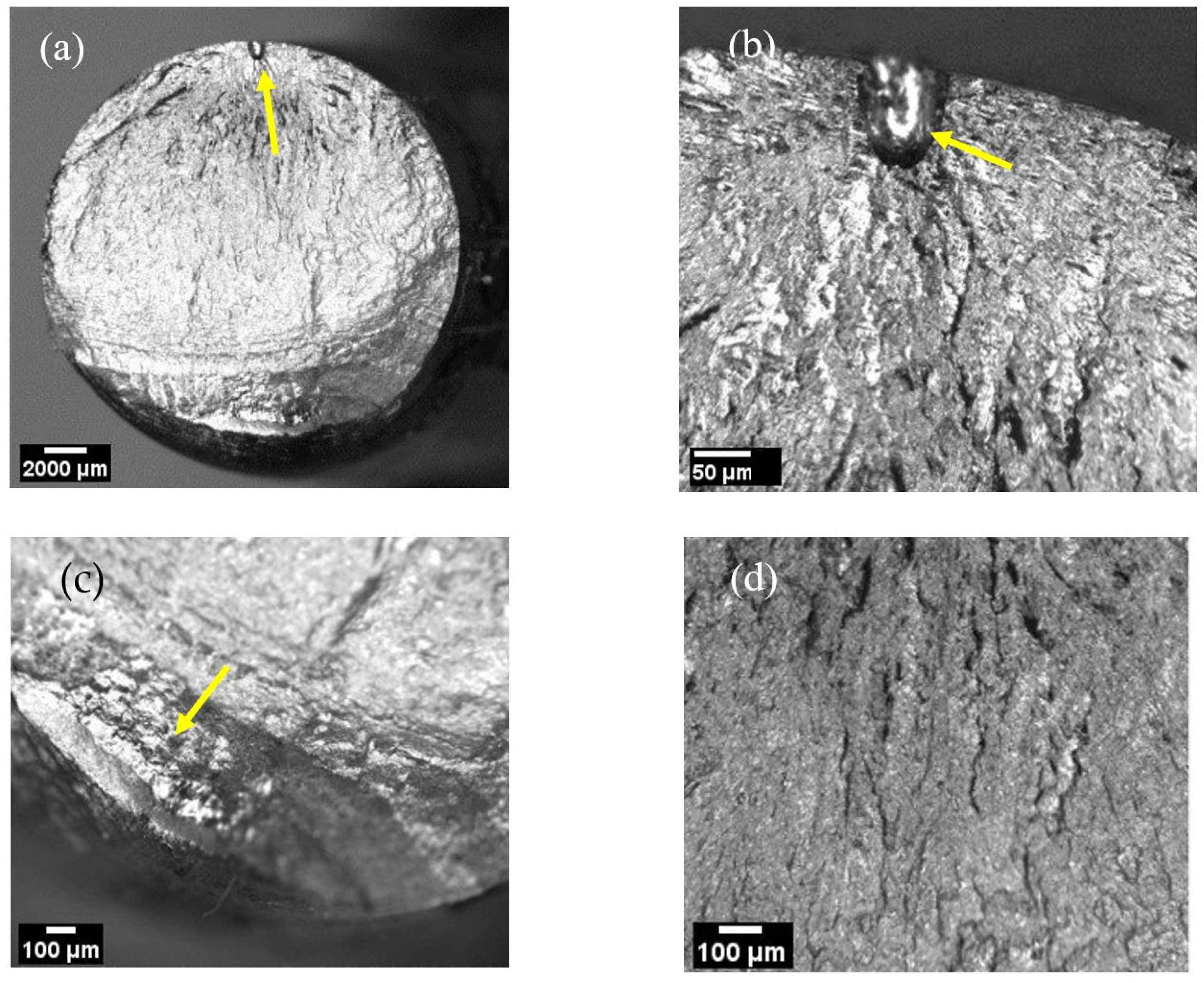
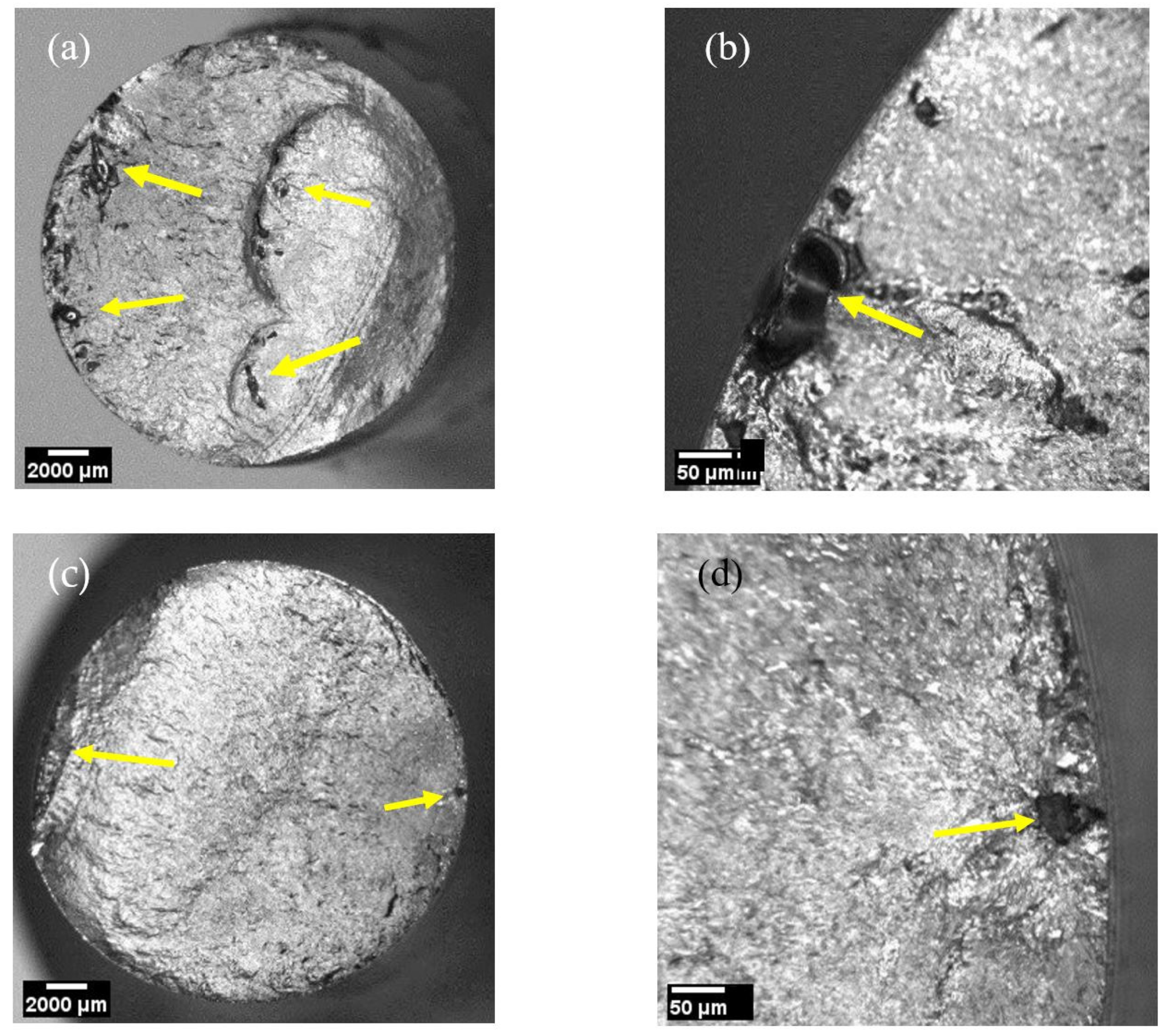
Standard tensile testing of the fabricated specimens showed a predominantly ductile fracture. The YS values were in the range of 642–725 MPa, with the UTS being 840–925 MPa. This critical elongation confirmed the ductile mechanism of failure and ranged between 21% and 32% within the as-deposited material. These values are in good agreement with the mechanical properties of SDSS found in the previous literature [23].
The summary of the conducted fatigue tests is presented in Figure 4 together with fatigue data for two SDSS, SAF 2205 and SAF2507 base materials [19]. In contrast to the monotonic loading data, fatigue results showed a strong anisotropic behaviour between longitudinal (along the deposition direction) and transverse (perpendicular to deposition) directions, see Figure 2. For example, the fatigue limit (at 106 cycles) for longitudinal specimens is almost twice that of transverse specimens. This could be attributed to the interlayer fusion zone and the presence of secondary austenite due to the reheating between bead layers, as shown in previous research [24,25,26], however this was not investigated in this study and will be the subject of future work. The fatigue limit range from 300 MPa to 325 MPa (~46% and 50% of YS, respectively) was achieved for the longitudinal direction with 2 × 10⁶ cycles completed. Internal defects and phase balance were potentially attributed to limiting the maximum stress for some specimens. For instance, specimen 26L3 (Figure 5) exhibited 2.12 × 10⁶ cycles at maximum stress of 350 MPa, yet had a notable internal pore defect of ~0.35 mm in diameter. Specimens 26L4 (Figure 6 ahead) and 26L6 showed notable pores of approximately <350 μm, achieving only 25 × 104 and 44 × 104 at 325 MPa and 350 MPa, respectively.
Alternatively, the transverse test specimens resulted in much lower fatigue limit stress values. Maximum stress amplitude values commenced at 400 MPa in the fatigue tests; however, the stress amplitude decreased rapidly and resulted in some confidence that the fatigue limit was around 175 MPa (in transverse direction). Specimens 26T5 and 26T6 in Figure 7 showed the number of cycles of 1.62 × 10⁶ and 2.02 × 10⁶, respectively. While the latter specimen did not fail after 2.02 × 10⁶ cycles, 26T6 (Figure 7), exhibited minor gas pores of >0.1 mm failure had initiated. Both 26T1 and 26T4 failed due to large scattered internal defects at ~2.5 × 10⁵; however, the maximum stresses applied were 300 MPa and 250 MPa, respectively, indicating that the size of these defects influenced early failure. Although the defect sizes do not show a consistent relationship to any number of cycles to failure, the results indicate evidence of large, imbedded defects of >500 μm, which must be avoided; therefore, volumetric non-destructive testing is required to detect these types of flaws. The results show that the smaller dimensioned flaws seen in 26L3 can be tolerated. This specimen failed at 2.12 × 10⁶ and exhibited a <0.05 mm sized defect.
The observations made during the fractography indicated multiple internal and external defects, particularly as shown in Figure 5, Figure 6 and Figure 7, which were identified as gas pores, wormholes and cluster pores, typically seen in gas metal arc (GMA) welding processes [11]. Interestingly, crack initiations not only occurred due to external gas pores, but were also initiated from the specimen internal defects, as shown in Figure 5a,d, Figure 6a,b and Figure 7a–d. This indicates the significance of crack initiation sites caused by imbedded defects, which are prone to GMA–WAAM processes.

3.3. Fractography

Fractography analysis was carried out on six specimens from 25 fatigue specimens (numbered from 26L1 to 26L6 and 27L1 to 27L7 to represent longitudinal direction, and 26T1 to 26T6 and 27T1 to 27T6 to represent transverse direction) to identify ductile, brittle features, as well as defects, propagation, and failure mode crack initiation sites. Both sides of the broken test specimens were investigated with optical microscopy.
Fractography surfaces revealed several areas of internal and external defects typically seen for the gas metal arc (GMA) welding process. These defects, identified predominantly as gas pores, were crack initiation sites that led to the failure of the specimens, highlighting the significance that volumetric defects have on the fatigue life.
Of the test specimens that were analysed, all showed varying internal defects, as described above. Additionally, there was no evidence of fusion defects commonly induced by WAAM-CMT processes, although this is somewhat mitigated with the oscillation procedure that was implemented. Figure 5 shows the failure surfaces of a fatigue specimen, which displays a typical ductile failure mode and multiple internal pores as defects. The crack initiation is shown in Figure 5a from an imbedded gas pore, which then led to the ultimate failure of the specimen at 25 × 10−4 cycles. The average pore size was approximately 350 μm with a maximum pore size of approximately 750 μm. Similar defect features and fracture morphology were evident in specimens 26L4, 27T4 and 27T6, as shown in Figure 6 and Figure 7, which was indicative of a large portion of specimens tested.
It must be noted that no external surface defects were observed upon visual inspection after the machining of test specimens. However, during the examination of fractography surfaces, external and surface flaws were present, and thus radiographic testing for detecting internal flaws, as well as dye penetrant inspection for external flaws, may be needed for future fatigue specimens.
The tensile properties of the longitudinal and transverse specimens fabricated by WAAM were found to be relatively close to each other (i.e., isotropic) and these basic properties were also within the range of the corresponding values reported for other manufacturing methods (e.g., casting and forging). However, the mechanical testing in the High-Cycle Fatigue (HCF) regime demonstrates a strong anisotropy in fatigue resistance for different directions. For instance, the fatigue limits for longitudinal (along the deposition direction) and transverse (perpendicular to the deposition direction) specimens were found to be significantly different. The fatigue limit at 106 cycles for longitudinal samples is almost twice that of transverse specimens. Both fatigue limit values were generally much lower than those reported for other manufacturing methods (see Figure 4). This large difference in the fatigue resistance, along with isotropic behaviour under monotonic loading can likely be attributed to: (1) the interlayer fusion zone and the presence of secondary austenite due to the reheating between bead layers as discussed above; as well as (2) manufacturing defects, which were described above and identified as gas pores, wormholes and cluster pores. These defects create strong stress concentrations leading to initiations of fatigue cracks and premature fatigue failures, as shown in Figure 5, Figure 6 and Figure 7. It is also hypothesised that the shape and arrangement of these defects in a WAAM-fabricated structure is such that the stress concentrations in the transverse direction are higher than those in the longitudinal direction, and form the basis of future research with the aim of reducing defects and improving transverse conditions. This hypothesis is yet to be confirmed with micro-CT examinations, which will be completed in the future. Almost no difference was found in the fatigue resistance (number of cycles to failure) of specimens with fatigue cracks initiated from specimen surfaces and internal defects.

4. Conclusions

The current experimental findings have important implications for design against the fatigue of structures fabricated by WAAM. These findings suggest simple rules, which can be utilised to improve fatigue life. The strong anisotropy in the fatigue properties dictates the preferable use of specific directions for deposition of layers. It is clear that the deposition direction along the maximum (or first) principal stress is beneficial for the fatigue resistance and generally improves the fatigue life of structures. The effect is stronger for structures working under a bi-axial stress state with a large difference in principal stresses; for example, for components subjected to pure shear. Therefore, the standard FE analysis, which is often integrated into design procedures, can provide not only the information regarding stress/strain distributions but can also guide the manufacturing and optimisation of the fatigue resistance of engineering components working under cyclic loading conditions.
The observed internal fatigue crack initiations for many tested fatigue specimens indicate that post-manufacturing surface treatments may not be a very effective way to improve the fatigue resistance of SDSS components fabricated by WAAM. In this respect, the focus on improvements must be directed towards the selection of WAAM processing parameters, such as deposition rates, bead placement, wire diameters and interpass temperatures. By an appropriate selection of these parameters, it is possible to improve the quality of fabricated components and avoid large manufacturing defects or, at least, reduce their sizes and increase densities. In other words, surface treatments, such as post process machining or polishing, can be effective when the dominant failure mechanisms are largely associated with surface defects and/or a high level of residual stresses near the surfaces.

Author Contributions

Conceptualization, all authors; Investigation, testing, results, interpretation of results and writing of original draft, A.S.; Interpretation of data, all authors A.S., A.K. and L.Y.; Writing—review and editing, all authors A.S., A.K. and L.Y. All authors have read and agreed to the published version of the manuscript.

Funding

This research was funded by AML3D Ltd, Adelaide, Australia and the ECMS Research Themes Seed Funding Scheme 2021, The University of Adelaide, Australia.

Data Availability Statement

Further additional data may be obtained by request to the corresponding author.

Acknowledgments

AML3D Limited is acknowledged for fabricating the test specimens and supporting this research. The authors would like to acknowledge Srikara Prabhakar Rao, Ujwal Seelam Badrinath and Yash Nayankumar Joshi for their help and time associated with the fatigue testing. They also thank the support of the ECMS Research Themes Seed Funding Scheme 2021 from the Faculty of Engineering, Computer and Mathematical Sciences, The University of Adelaide.

Conflicts of Interest

The authors declare no conflict of interest.

References

  1. Murr, L.E. Global trends in the development of complex, personalized, biomedical, surgical implant devices using 3D printing/additive manufacturing: A review. Med. Devices Sens. 2020, 3, e10126. [Google Scholar] [CrossRef]
  2. Murr, L.; Johnson, W.L. 3D metal droplet printing development and advanced materials additive manufacturing. J. Mater. Res. Technol. 2017, 6, 77–89. [Google Scholar] [CrossRef]
  3. Wu, Q.; Mukherjee, T.; De, A.; DebRoy, T. Residual stresses in wire-arc additive manufacturing—Hierarchy of influential variables. Addit. Manuf. 2020, 35, 101355. [Google Scholar] [CrossRef]
  4. Williams, S.W.; Martina, F.; Addison, A.C.; Ding, J.; Pardal, G.; Colegrove, P. Wire+ arc additive manufacturing. Mater. Sci. Technol. 2016, 32, 641–647. [Google Scholar] [CrossRef] [Green Version]
  5. Rodrigues, T.A.; Duarte, V.; Miranda, R.M.; Santos, T.G.; Oliveira, J.P. Current Status and Perspectives on Wire and Arc Additive Manufacturing (WAAM). Materials 2019, 12, 1121. [Google Scholar] [CrossRef] [PubMed] [Green Version]
  6. AWS D20.1D20.1 2019 Specification for Fabrication of Metal Components using additive manufacturing.
  7. PAS6010 Additive Manufacturing—Wire for directed energy deposition (DED) processes in additive manufacturing—Specification.
  8. ASTM F3187-16—Standard Guide for Direct Energy Deposition of Metals.
  9. ISO-ASTM 52900-15—Additive Manufacturing.
  10. Wu, B.; Pan, Z.; Ding, D.; Cuiuri, D.; Li, H.; Xu, J.; Norrish, J. A review of the wire arc additive manufacturing of metals: Properties, defects and quality improvement. J. Manuf. Process. 2018, 35, 127–139. [Google Scholar] [CrossRef]
  11. Xiong, J.; Li, Y.; Li, R.; Yin, Z. Influences of process parameters on sur-face roughness of multi-layer single-pass thin-walled parts in GMAW-based additive manufacturing. J. Mater. Process. Technol. 2018, 252, 128–136. [Google Scholar] [CrossRef]
  12. Wächter, M.; Leicher, M.; Hupka, M.; Leistner, C.; Masendorf, L.; Treutler, K.; Kamper, S.; Esderts, A.; Wesling, V.; Hartmann, S. Monotonic and Fatigue Properties of Steel Material Manufactured by Wire Arc Additive Manufacturing. Appl. Sci. 2020, 10, 5238. [Google Scholar] [CrossRef]
  13. Nikam, P.P.; Arun, D.; Ramkumar, K.D.; Sivashanmugam, N. Microstructure characterization and tensile properties of CMT-based wire plus arc additive manufactured ER2594. Mater. Charact. 2020, 169, 110671. [Google Scholar] [CrossRef]
  14. Zhang, J.; Wang, X.; Paddea, S.; Zhang, X. Fatigue crack propagation behaviour in wire+arc additive manufactured Ti-6Al-4V: Effects of microstructure and residual stress. Mater. Des. 2016, 90, 551–561. [Google Scholar] [CrossRef]
  15. Dirisu, P.; Ganguly, S.; Mehmanparast, A.; Martina, F.; Williams, S. Analysis of fracture toughness properties of wire + arc additive manufactured high strength low alloy structural steel components. Mater. Sci. Eng. A 2019, 765. [Google Scholar] [CrossRef]
  16. Duraisamy, R.; Kumar, S.M.; Kannan, A.R.; Shanmugam, N.S.; Sankaranarayanasamy, K. Fatigue Behavior of Austenitic Stainless Steel 347 Fabricated via Wire Arc Additive Manufacturing. J. Mater. Eng. Perform. 2021, 30, 6844–6850. [Google Scholar] [CrossRef]
  17. Karlsson, L. Welding of duplex stainless steels—A review of current recommendations. Weld. World 2012, 56, 65–76. [Google Scholar] [CrossRef]
  18. Kannan, A.R.; Shanmugam, N.S.; Rajkumar, V.; Vishnukumar, M. Insight into the microstructural features and corrosion properties of wire arc additive manufactured super duplex stainless steel (ER2594). Mater. Lett. 2020, 270, 127680. [Google Scholar] [CrossRef]
  19. Polak, J. Cyclic Plastic Response and Fatigue Life of Duplex and SuperDuplex Stainless Steels. Kov. Mater. 2005, 43, 280–289. [Google Scholar]
  20. Björk, T.; Mettänen, H.; Ahola, A.; Lindgren, M.; Terva, J. Fatigue strength assessment of duplex and super-duplex stainless steels by 4R method. Weld. World 2018, 62, 1285–1300. [Google Scholar] [CrossRef]
  21. Akdut, N. Phase morphology and fatigue lives of nitrogen alloyed duplex stainless steels. Int. J. Fatigue 1999, 21, 97–103. [Google Scholar] [CrossRef]
  22. Stützer, J.; Totzauer, T.; Wittig, B.; Zinke, M.; Jüttner, S. GMAW Cold Wire Technology for Adjusting the Ferrite–Austenite Ratio of Wire and Arc Additive Manufactured Duplex Stainless Steel Components. Metals 2019, 9, 564. [Google Scholar] [CrossRef] [Green Version]
  23. ASTM. E8/E8M-16A Standard Test Methods for Tension Testing of Metallic Materials; ASTM: West Conshohocken, PA, USA, 2016. [Google Scholar]
  24. Lervåg, M.; Sørensen, C.; Robertstad, A.; Brønstad, B.M.; Nyhus, B.; Eriksson, M.; Aune, R.; Ren, X.; Akselsen, O.M.; Bunaziv, I. Additive Manufacturing with Superduplex Stainless Steel Wire by CMT Process. Metals 2020, 10, 272. [Google Scholar] [CrossRef] [Green Version]
  25. Mateo, A.; Llanes, L.; Akdut, N.; Stolarz, J.; Anglada, M. Anisotropy effects on the fatigue behaviour of rolled duplex stainless steels. Int. J. Fatigue 2003, 25, 481–488. [Google Scholar] [CrossRef]
  26. Jebaraj, A.V.; Kumar, L.A.; Deepak, C. Investigations on Anisotropy Behavior of Duplex Stainless Steel AISI 2205 for Optimum Weld Properties. Procedia Eng. 2017, 173, 883–890. [Google Scholar] [CrossRef]
Figure 1. (a) Typical WAAM equipment, including a robotic arm and a positioner table, and (b) WAAM bead layering in process (published with permission of AML3D Ltd.).
Metals 11 01965 g001
Figure 2. A ER2594 SDSS test wall fabricated by WAAM.
Metals 11 01965 g002
Figure 3. Test specimen dimensions.
Metals 11 01965 g003
Figure 4. Stress amplitudes, σ a vs. the number of cycles to failure, N f and comparison with the fatigue data for SAF 2205 and SAF2507 [19].
Metals 11 01965 g004
Figure 5. Macro of the fracture surfaces of specimen 26L3 at magnifications of (a) 0.8×; (b) 4 ×, indicating a gas pore; (c) 2.5×; and (d) 1.6×, showing fibrous fracture morphology and with (d) showing crack initiation.
Metals 11 01965 g005
Figure 6. Fracture faces of 26L4 showing gas pore defect at magnifications of (a) 0.8×, (b) 4×, (c) 2×, and (d) 2.5×, showing crack initiation site and fibrous fracture morphology.
Metals 11 01965 g006
Figure 7. Fracture faces of transverse specimens of 26T4 and 27T6, both showing external gas pores defects at magnifications of (a) 0.8× and (b) 4×, with (c) 0.8× indication crack initiation site and an external gas pore which is magnified in (d) 4×.
Metals 11 01965 g007
Table 1. Chemical composition of the ER2594 wire (wt.%).
CMnWSiCrNiMoNCuFe
0.0140.57<0.010.3225.369.223.990.250.08Balance
Table 2. WAAM Deposition Parameters.
ParametersValues
Contact tip to work distance (CTWD)15.0 mm
Wire diameter1.2 mm
Shielding gas80% Ar + 20% CO2
Flow rate20 L/min
Inter-pass temperature150 °C
Wire-feed speed (WFS)9.0 m/min
Travel speed (TS)0.6 m/min
WFS/TS15
Layer height (LH)2.5 mm
Publisher’s Note: MDPI stays neutral with regard to jurisdictional claims in published maps and institutional affiliations.

