Article

Fundamental Research on Fluorine-Free Ladle Furnace Slag for Axle Steel of Electric Multiple Unit Vehicles

1
Key Laboratory for Ecological Metallurgy of Multimetallic Mineral (Ministry of Education), Northeastern University, Shenyang 110819, China
2
School of Metallurgy, Northeastern University, Shenyang 110819, China
3
Jiangyin Xingcheng Special Steel Works Co., Ltd., Wuxi 214400, China
4
Technology Center, Shanxi Taigang, Stainless Steel Co., Ltd., Taiyuan 030003, China
5
Process and Systems Engineering Laboratory, Åbo Akademi University, 20500 Turku, Finland
*
Author to whom correspondence should be addressed.
Metals 2021, 11(12), 1973; https://doi.org/10.3390/met11121973
Submission received: 24 October 2021 / Revised: 29 November 2021 / Accepted: 6 December 2021 / Published: 8 December 2021
(This article belongs to the Special Issue Advances in Slag Metallurgy)

Abstract

:
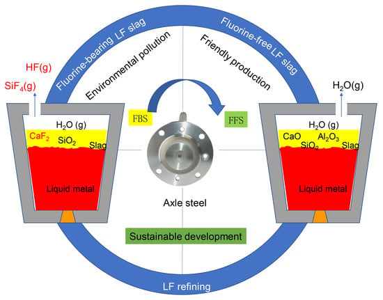
Fluorine-bearing refining slag (FBS) is used to produce axle steel for electric multiple unit vehicles. To avoid environmental pollution caused by fluorine, a fluorine-free ladle furnace slag (FFS) was designed based on an industrial FBS. The effects of main components on the physical and metallurgical properties of slag were investigated via theoretical analysis and laboratory tests. The composition range of components of the designed FFS are w(CaO) = 40–55 wt.%, w(SiO2) = 2–6 wt.%, w(Al2O3) = 30–40 wt.%, w(MgO) = 6–8 wt.%, and w(CaO)/w(Al2O3) = 1.25–1.50. Industrial-scale test results indicate that the FFS has similar deoxidation and desulfurization capabilities to industrial FBS.

Graphical Abstract

1. Introduction

China has the world’s largest high-speed rail network. Axle steel is a special steel used to manufacture the axles of electric multiple unit (EMU) vehicles, which guarantees safe transportation. The oxygen content and level of inclusions are of vital importance to the properties of axle steel, and therefore refining plays a significant role in the melting process [1]. It was shown that an appropriate refining slag plays a significant role in improving the quality of steel products [2,3]. Some components of the refining slag were found to affect the slag viscosity and melting characteristics [4,5]. Therefore, the refining slag composition must be strictly controlled within limits to meet the melting requirements.
In China, the adopted production of axle steel is generally the electric arc furnace (EAF) → ladle furnace (LF) → vacuum degassing or Ruhrstahl-Heraeus process (VD or RH) → continuous casting (CC) route. The LF slag of axle steel is mainly designed based on a high-basicity CaO-Al2O3 slag system [6], and the mass ratio of CaO to Al2O3 is usually in the range w(CaO)/w(Al2O3) = 1.0–2.0 [7]. In addition, calcium fluoride is widely used as fluxes to satisfy the slag high-temperature physicochemical properties during the LF process. Studies have shown that the introduction of CaF2 to the CaO-A12O3-SiO2-MgO system lowers the melting point and viscosity, thus improving the fluidity of the slag [8,9,10,11,12]. Recently, the mechanisms by which slag components affect the behavior of the slag melt have been studied by molecular dynamics and Raman spectroscopy [13,14]. Zhang and co-workers proposed that CaF2 can depolymerize the network structure of the melt in the CaO-Al2O3-CaF2 system and studied means of improving the fluidity of the slag based on molecular dynamics simulations [14].
However, calcium fluoride will react with SiO2 to generate the low melting point SiF2 that tends to evaporate in the atmosphere during the melting process [15]. Zhao et al. investigated the volatilization characteristics of three kinds of typical fluorine-containing slag systems for steelmaking process, being the remelting electroslag, the continuous casting mold flux, and the traditional refining slag [16]. Results show that the CaF2-CaO refining slag system generates mounts of SiF4, and the volatility can be reduced by adding a small amount of SiO2. Using thermodynamic calculation, Mao and co-workers proposed that the volatiles are NaF, KF, SiF4, AlF3, NaAlF4, and HF during the continuous casting process [17]. Apparently, industrial releases from the steelmaking process are contributing to increased levels of fluoride in the environment. Therefore, it is urgent to develop environment-friendly fluorine-free refining slag for the refining process.
At present, extensive research has attempted to design fluorine-free mold flux, since more than 95% of the crude steel has been produced through the process of continuous casting technology [18]. The substitutes for fluorides in mold flux are primarily focused on TiO2, B2O3, and Na2O [19,20,21]. Although many industrial trials in fluorine-free mold flux were carried out and some claimed to successfully replace the conventional fluorine-bearing mold flux, while the majority of study is only limited to crack-insensitive steels [18]. Very few studies about fluorine-free refining slag have been conducted for the axle steel, which is a special railway axle steel. Therefore, the development of fluorine-free refining slag is of great significance to the sustainable and cleaner production of axle steel smelting.
The fluidity characteristic of slag, which contains the melting temperature and viscosity, is an important physicochemical property that determines the stability and productivity in steelmaking [22]. The choice of the initial composition of synthetic slag could have important implications for the secondary refining process [23]. Results showed that viscosity decreased with increasing MgO content (1–8 wt.%) and the mass ratio of CaO/Al2O3 (0.7~0.9) in the CaO-Al2O3-MgO slag system [24]. Moreover, the melting temperature increases first and then decreases with the increase of CaO/Al2O3 from 1.17 to 1.52 in the CaO-Al2O3-10 wt.% SiO2-based slags [22]. Therefore, a better understand the relationship between the properties of refining slag and components and the design of a fluorine-free LF slag (FFS) for cleaner production of EMU axle steel is the motivation for carrying out this work [25,26].
To achieve the goal of sustainable development, development at the expense of the environment can no longer be allowed. A fluorine-bearing LF slag (FBS) from a steel company in China was studied and redesigned in this work. The production route of the axle steel is EAF → LF → VD → CC. The effects of MgO, SiO2 and w(CaO)/w(Al2O3) of refining slag on the physical and metallurgical properties were theoretically and experimentally investigated. Furthermore, an FFS was designed and used in industrial-scale tests to verify its performance.

2. Research Methods

2.1. Theoretical Analysis

To explore the effects of MgO content (5–10 wt.%), SiO2 content (2–14 wt.%), and w(CaO)/w(Al2O3) on the basic physical and metallurgical properties of the CaO-Al2O3-SiO2-MgO-CaF2 system, several multicomponent phase diagrams, isothermal cross-section diagrams, liquid phase area diagrams, and iso-activity diagrams were studied with the help of FactSage 8.0 software (Thermfact/CRCT, Montreal, Canada and GTT-Technologies, Aachen, Germany). The thermodynamic data of the liquid phase and pure solid phase in the slag were selected from the FactPS and FToxid databases, respectively.

2.2. Laboratory Tests

An FFS system was proposed and studied based on theoretical analysis. Moreover, the chemical composition of the FFS was further optimized based on the results of an investigation of the viscosity and melting point of the experimental slags. The chemical compositions of the experimental slags are listed in Table 1, corresponding to different SiO2 contents (No. 1, 2, and 3) and w(CaO)/w(Al2O3) ratios (No. 2, 4, and 5). In addition, the sample of FBS (No. 6) used by the axle steel plant (Stainless steel Co., Ltd., Taiyuan, China) was also tested under the same conditions, with the purpose of comparing the properties of the FFS and FBS slags.
High-grade pure calcium oxide (CaO), magnesium oxide (MgO), silica (SiO2), aluminum oxide (Al2O3), and calcium fluoride (CaF2) were employed to prepare experimental slags. CaO was calcinated at 1273 K in air atmosphere for 10 h to remove H2O and CO2. After that, the chemical reagents were uniformly mixed for the laboratory tests.
The rotating cylinder method was used to test the viscosity of the experimental slags. About 140 g of the pre-melted slag sample was put into a graphite crucible (φ 40 mm × 80 mm) lined with Mo sheet and heated to 1823 K under Ar atmosphere, which was kept for 30 min for a complete melting. A Mo spindle (φ 10 mm × 25 mm) was placed in the center of the graphite crucible and slowly lowered into the molten slag to a level 10 mm from the crucible bottom. The spindle was rotated with a speed of 200 rpm during the continuous viscosity measurement period. To ensure that the measured value is close to the equilibrium viscosity, the cooling rate of the rotating viscometer furnace (RTW-16, China) was set as 3 K·min−1. The test was stopped when the viscosity of the slag was 2 Pa·s, and the viscosity and temperature were recorded continuously at intervals of 0.1 K.
The quenched slag sample obtained after the viscosity measurement was dried and crushed as a specimen for the following melting-point test. The melting property of the slag was studied by a standard method [27]. The melting point, considered to be the hemisphere point temperature, was measured by melting point and melting rate detectors. A small cylindrical 3 mm high specimen, with a diameter of 3 mm, was used for each test. The sample was placed on an alumina plate on the sample-holder, which was heated at a rate of 10 K·min−1. The changes in the shape of the samples during heating were observed with a microscope. The temperature at which the sample showed a shrinkage of 50% was considered as the melting temperature. Each experiment was repeated three times and the average value of the results was taken and reported.

2.3. Industrial Scale Tests

Three sets of industrial scale tests were carried out to evaluate the smelting effects of the designed FFS. Table 2 lists the chemical compositions of the slag for the industrial scale tests. The chemical composition of No. #1 is within the optimized range obtained by the laboratory study, while #2 is not but has the same w(CaO)/w(Al2O3) ratio as FBS (No. #3). The final (No. #3) is a slag from the axle steel plant, which has a similar chemical composition as No. 6 studied in the laboratory tests.
The industrial scale tests of axle steel were carried out in a steel plant in China. The production route is 80 t EAF → LF → VD → CC. Table 3 shows the composition requirement of axle steel. The endpoint carbon and phosphorus contents of EAF were controlled on average 0.20 wt.% and 0.002 wt.%, respectively, for three industrial tests. For industry test No. #3, the refining slag (400 kg), fluorite (100 kg), and lime (400 kg) were added for slagging when tapping. Aluminum shot (250 kg), silicon-manganese alloy (500 kg), micro carbon ferrochrome (VCr3, 1100 kg), and ferromolybdenum (250 kg) were used for deoxidation and alloying. The tapping weight per furnace of 8.2 t. in the earlier stage of LF refining, the deoxidization process of feeding aluminum wire was applied according to the deoxidation condition. Lime and fluorite were added to make reductive slag during the LF refining. After deoxidation and slagging, silicon-manganese alloy, manganese, ferromolybdenum, and ferrovanadium were added to adjust the composition of molten steel according to the target composition of axle steel. Additionally, the industry tests of No. #1 and #2 have the same LF refining conditions, except that fluorite was not added.
The smelting results of the designed FFS was evaluated by measuring the total oxygen and sulfur content in the steel samples. Steel was sampled from two positions, including early LF and after LF. Cylindrical samples (Φ 4 mm × 5 mm) were machined from the steel sample after LF and used to analyze the total oxygen and sulfur content. The contents of sulfur in the steel sample were determined by the infrared carbon and sulfur detector (CS-2300, America). The total oxygen content was measured by oxygen and nitrogen analyzer (ON736, America). Furthermore, the cylindrical samples were embedded in epoxy resin, polished by SiC paper, and diamond suspensions for further analysis. The inclusions in the steel were analyzed by scanning electron microscopy (Phenom ProX, China) with energy-dispersive X-ray spectroscopy (SEM-EDS).

3. Results and Discussion

3.1. Theoretical Analysis

3.1.1. MgO

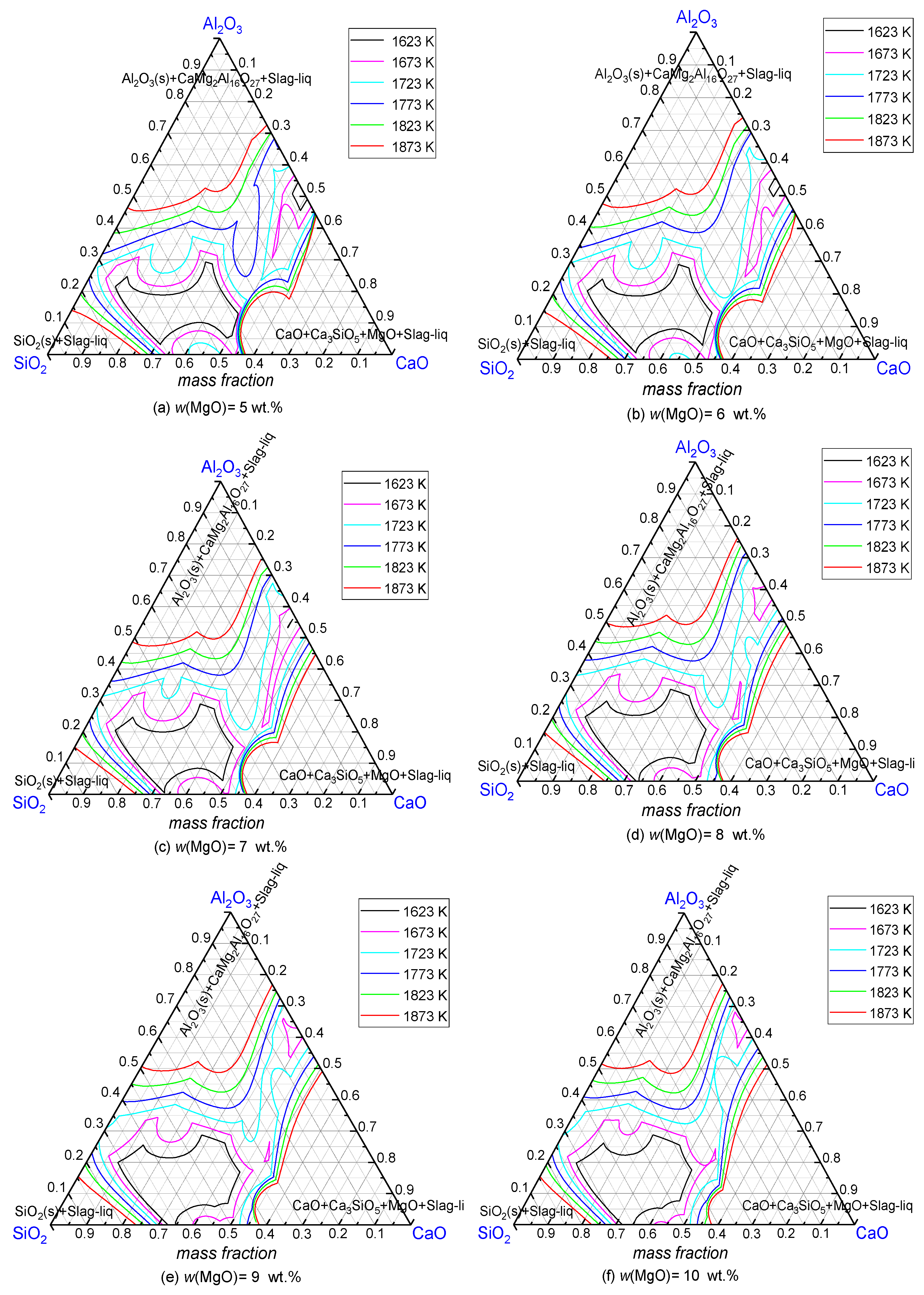
Figure 1 shows isothermal cross-section diagrams of CaO-Al2O3-SiO2-xMgO (x = 5–10 wt.%) at 1873 K. It can be seen that MgO phase can exist in the slag when its MgO content is 6–10 wt.%. Moreover, the stable existence area of MgO expands with the increase in the MgO content, showing the same trend as reported the literature [28,29]. Magnesia-carbon (MgO-C) refractories are widely used in the ladle slag line. Therefore, the MgO content in the studied system should be controlled in the range of 6–10 wt.%, aiming to reduce the damage of the refining slag to the furnace lining during the refining process [30]. Furthermore, the influence of the MgO content on the meltability of the slag should be considered [31,32]. The effects of MgO content of the CaO-Al2O3-SiO2-MgO system on the liquid phase area at different temperatures is shown in Figure 2. The liquid phase area of slag expands at 1873 K when the MgO content increases from 5 wt.% to 7 wt.%. This result indicated that the increase of MgO content (5–7 wt.%) improves the fluidity of slag. Likewise, Kim and co-workers [33] found that the addition of MgO decreased the viscosity of CaO-SiO2-20% Al2O3-MgO slag system. The main reason for this is a modification of the slag network structure with the addition of MgO. By contrast, the liquid phase area shrinks as the MgO content increases at 1873 K, if the content is in the range of 7–10 wt.%. The reason for this may be that a large amount of MgO precipitates in the slag and forms a high-melting-point spinel phase, resulting in an increase in the melting point of the slag [34]. Therefore, the MgO content in FFS is suggested to be controlled between 6 wt.% and 8 wt.%, which could protect the furnace lining and give the molten phase a workable melting performance.

3.1.2. SiO2

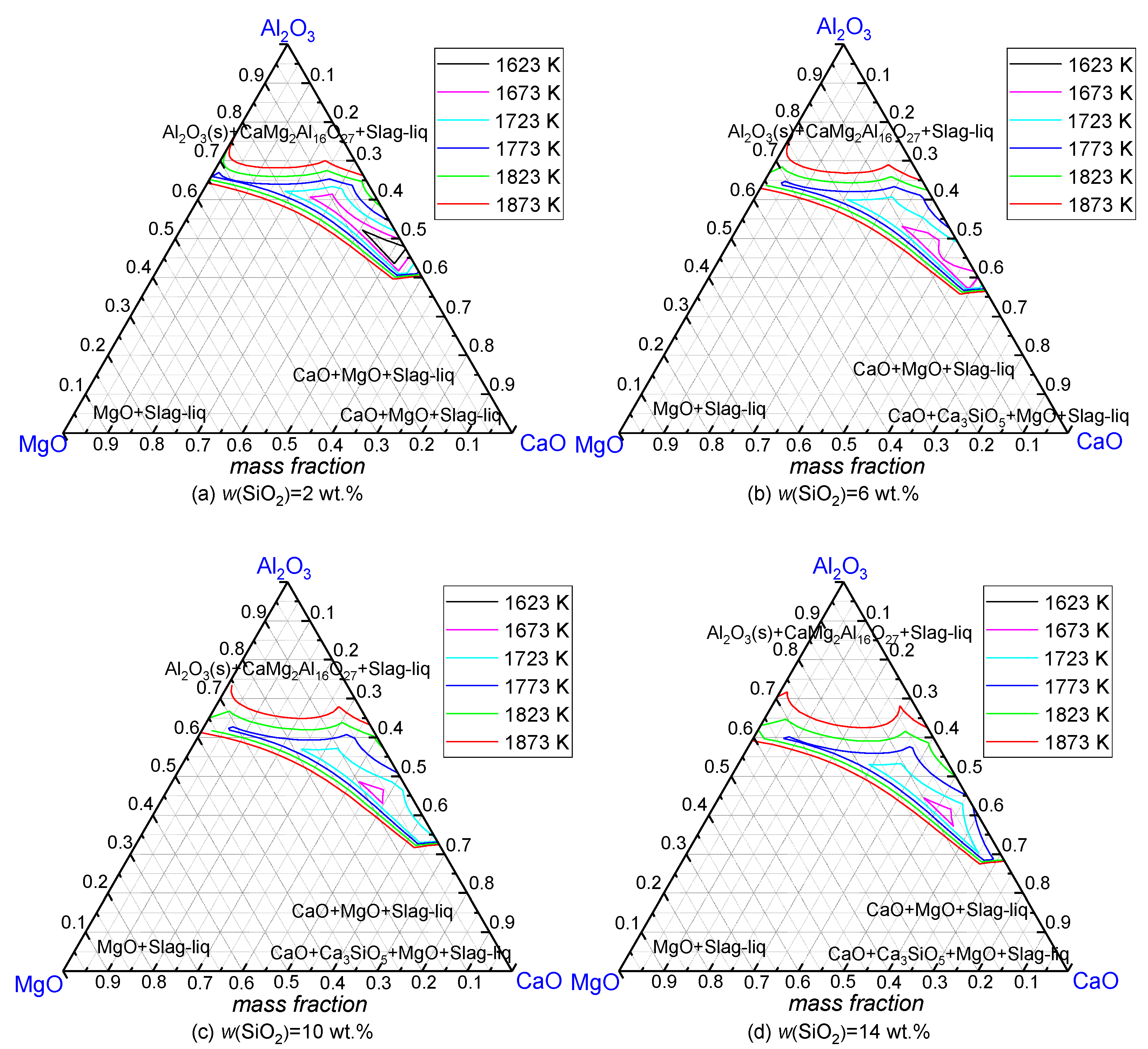
To investigate the effects of SiO2 content on the melting property of the FFS, liquid-phase area diagrams of the CaO-Al2O3-MgO-xSiO2 system with different SiO2 content (2–14 wt.%) are shown in Figure 3. It can be observed that the liquid phase area expands with SiO2 in the studied range at 1873 K. Therefore, it is beneficial to appropriately increase the SiO2 content of the slag to improve the melting performance of the slag.
However, it has been reported the SiO2 component in the refining slag affects the deoxidation reaction of the dissolved aluminum in the melt. As shown in Equation (1).
3 ( SiO 2 ) + 4 [ Al ] = 2 ( Al 2 O 3 ) + 3 [ Si ]
The SiO2 in the slag can oxidize the dissolved elemental aluminum in molten steel, subsequently results in lowering the deoxidization degree of the melt. Therefore, the activity of SiO2 in the slag should be reduced. Figure 4 shows iso-activities diagram of SiO2 in the CaO-Al2O3-SiO2-10 wt.% MgO system at 1873 K. The data was selected from the Slag Atlas [28] (black solid lines) and the FactSage 8.0 software database (red solid lines), respectively. There is a difference between the activity of SiO2 calculated by the two databases. It can be seen in Figure 4 that the activity of SiO2 is low when its content in the slag is less than 10 wt.%, which could prevent the oxidation of dissolved aluminum in the melt. Since some SiO2 could be brought from the raw materials and tapping of the EAF, the content of SiO2 of FFS is suggested to be controlled within the range of 2–10 wt.%.

3.1.3. Mass Ratio of w(CaO)/w(Al2O3)

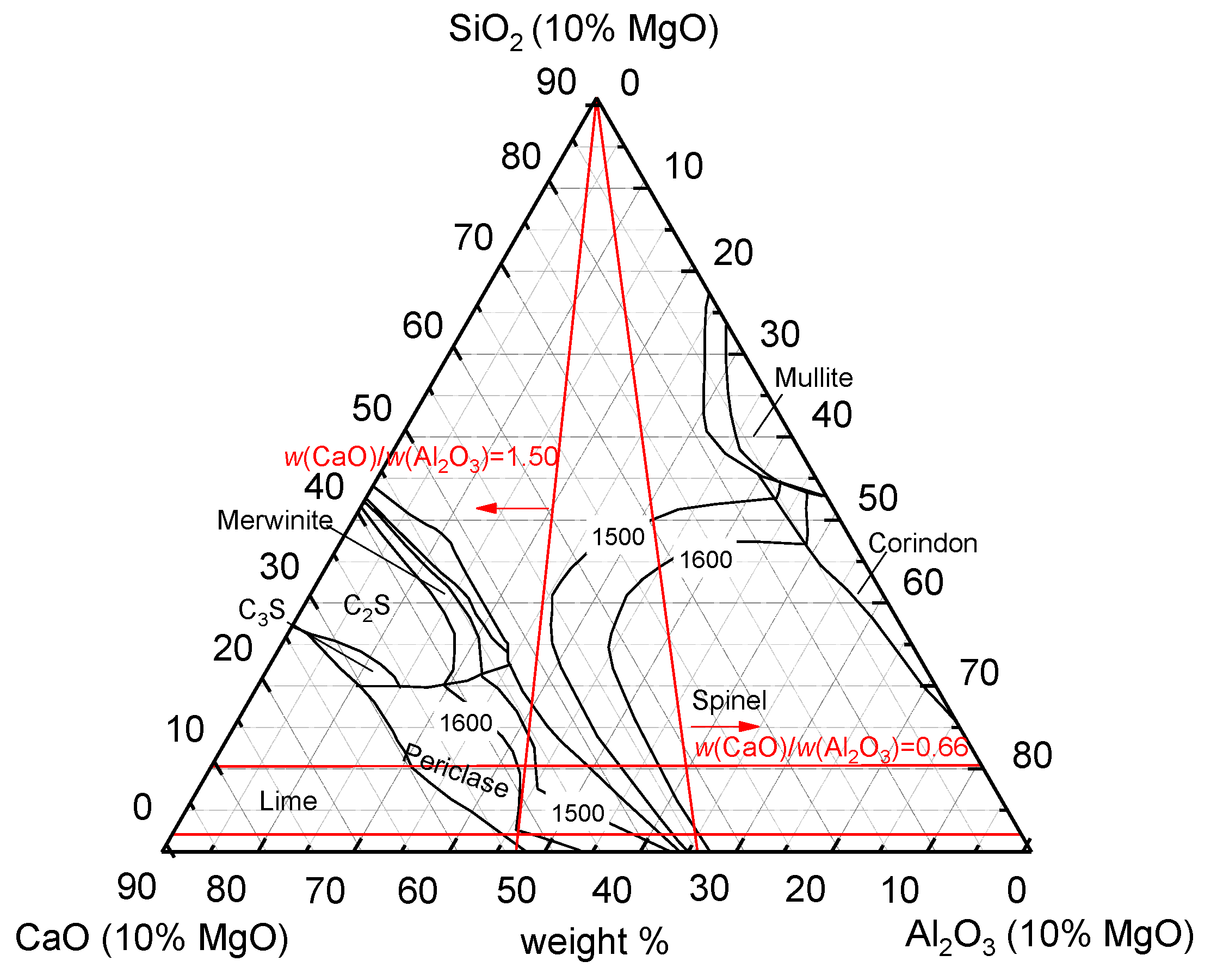
It is known from the binary phase diagram of CaO-Al2O3 and earlier experiences that the two components can react under LF conditions and form low-melting-point compounds, such as 12CaO·7Al2O3, affecting the metallurgical and melting properties of the slag. Figure 5 shows the pseudo ternary phase diagram of CaO-Al2O3-SiO2-10 wt.% MgO, which shows that when the SiO2 content is 2–10 wt.%, the liquid phase area at 1873 K is within the w(CaO)/w(Al2O3) range of 0.66–1.50. In the LF process, the refining slag absorbs the Al2O3 inclusions in the melt, causing a decrease in w(CaO)/w(Al2O3), and the absorption capacity of the slag has a stronger relationship with the Al2O3 and CaO activities in the molten phase. Therefore, the iso-activity curves of Al2O3 and CaO were plotted to find a means to further optimize the wt. ratio w(CaO)/w(Al2O3).
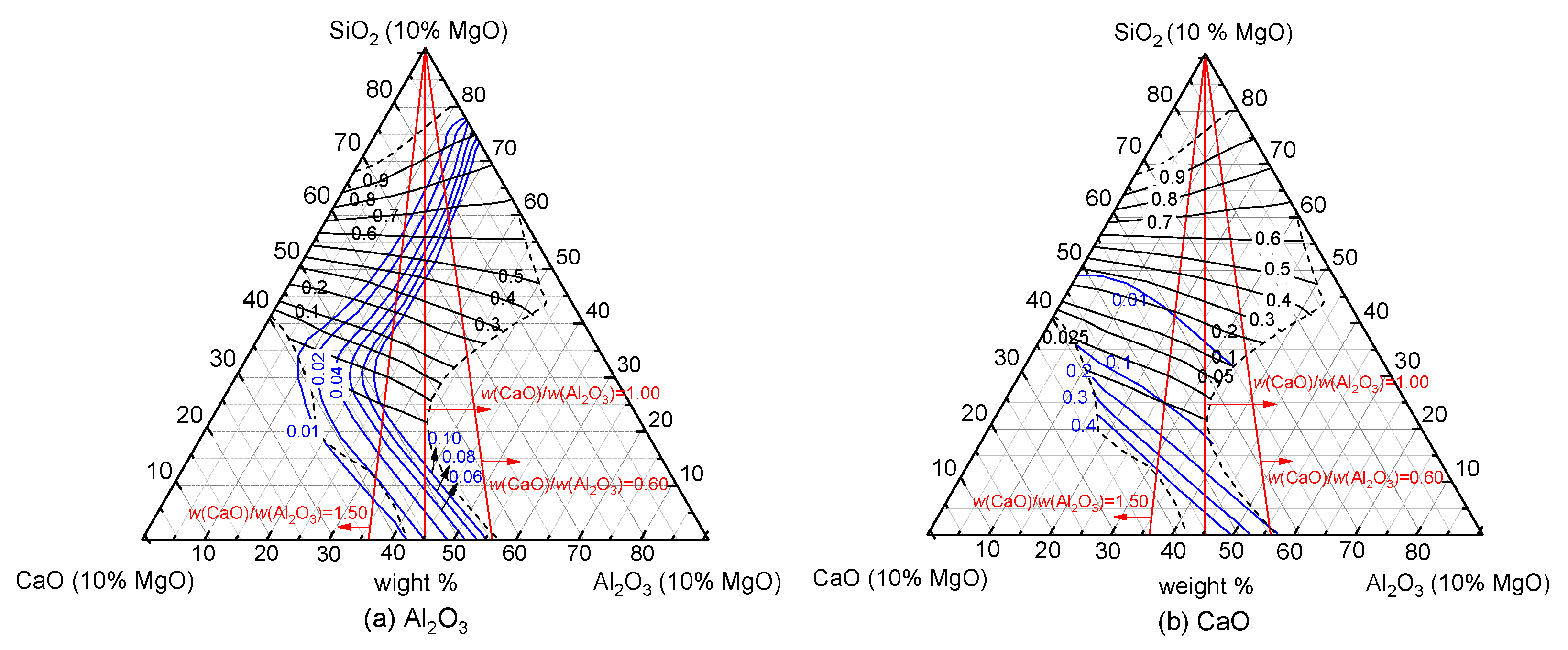
Figure 6a,b show the iso-activity diagrams of Al2O3 and CaO in the CaO-Al2O3-SiO2-10 wt.% MgO system, respectively, using data selected from the Slag Atlas (black solid line) and the FactSage 8.0 software database (blue solid line). The diagrams show that when the content of SiO2 in the slag is constant, the activity of Al2O3 in the melt decreases, and the activity of CaO increases with the w(CaO)/w(Al2O3) ratio [35]. Therefore, a high w(CaO)/w(Al2O3) ratio in a workable range is beneficial for the absorption of Al2O3 inclusions.

3.2. Laboratory Tests

Based on the discussion above, the preferable theoretical ranges for the chemical composition of the FFS for axle steel is proposed as w(CaO) = 40–55 wt.%, w(SiO2) = 2–10 wt.%, w(Al2O3) = 30–50 wt.%, w(MgO) = 6–8 wt.%, and w(CaO)/w(Al2O3) = 1.00–1.50. To further optimize the chemical composition of the FFS, the viscosity and melting point were determined. The chemical compositions studied are listed in Table 1.

3.2.1. SiO2

Viscosity-temperature curves of the samples are shown in Figure 7. All samples are seen to present a similar trend, where the viscosity of the slag slowly increases when the temperature decreases, but is above the break temperature. When the temperature decreases beyond the break temperature, the viscosity increases strongly.
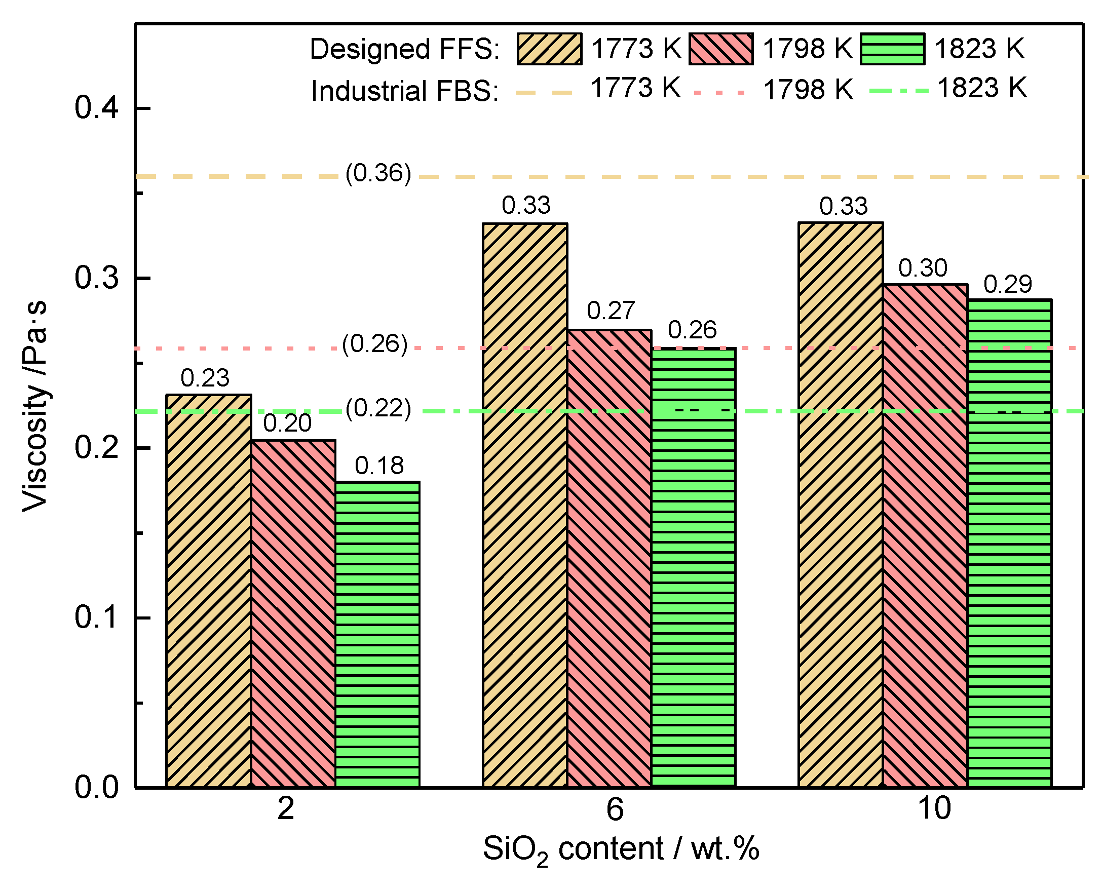
Figure 8 shows the viscosity-temperature bar graph of the experimental slags with different SiO2 contents. The viscosity of the samples increases as the SiO2 content increases from 2 wt.% to 10 wt.% at a constant temperature, which indicates that the increase in SiO2 content becomes rate-limiting for the mass transfer at the slag-melt interface region. The reason for this phenomenon is that SiO2 increases the tendency to network formation and the degree of polymerization of the refining slag [36,37]. Furthermore, comparing the viscosity values of the designed FFS and industrial FBS at the same temperature, it is seen that when the SiO2 content is 2 wt.%, the viscosity is less than that of the industrial FBS, and increases with the SiO2 content. As the SiO2 content reaches 6 wt.%, the viscosities of FFS and FBS show similar values. A higher SiO2 content, e.g., 10 wt.%, may seriously affect the fluidity of the slag.
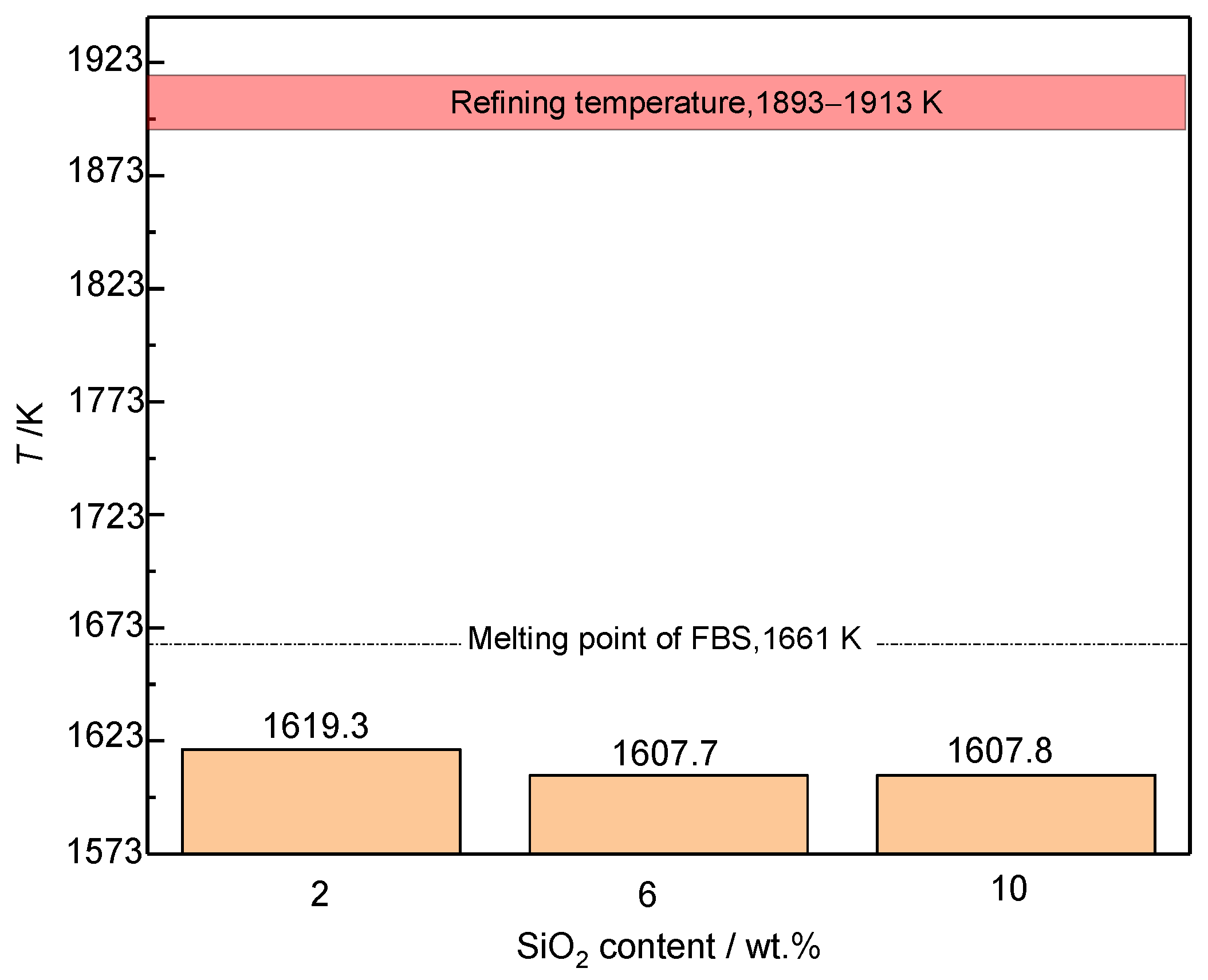
Figure 9 shows the melting point of slags of various contents of SiO2 (2–10 wt.%). When the SiO2 content increases from 2 wt.% to 10 wt.%, melting point of slag decreases slightly (from 1619 K to 1608 K), implying that the SiO2 has little effect on the melting point of the slag. The melting point of the designed FFS was lower than for the industrial FBS and much lower than the refining temperature (1893–1913 K). Based on these results, one may conclude that the preferable SiO2 content of FFS is 2–6 wt.%.

3.2.2. Mass Ratio w(CaO)/w(Al2O3)

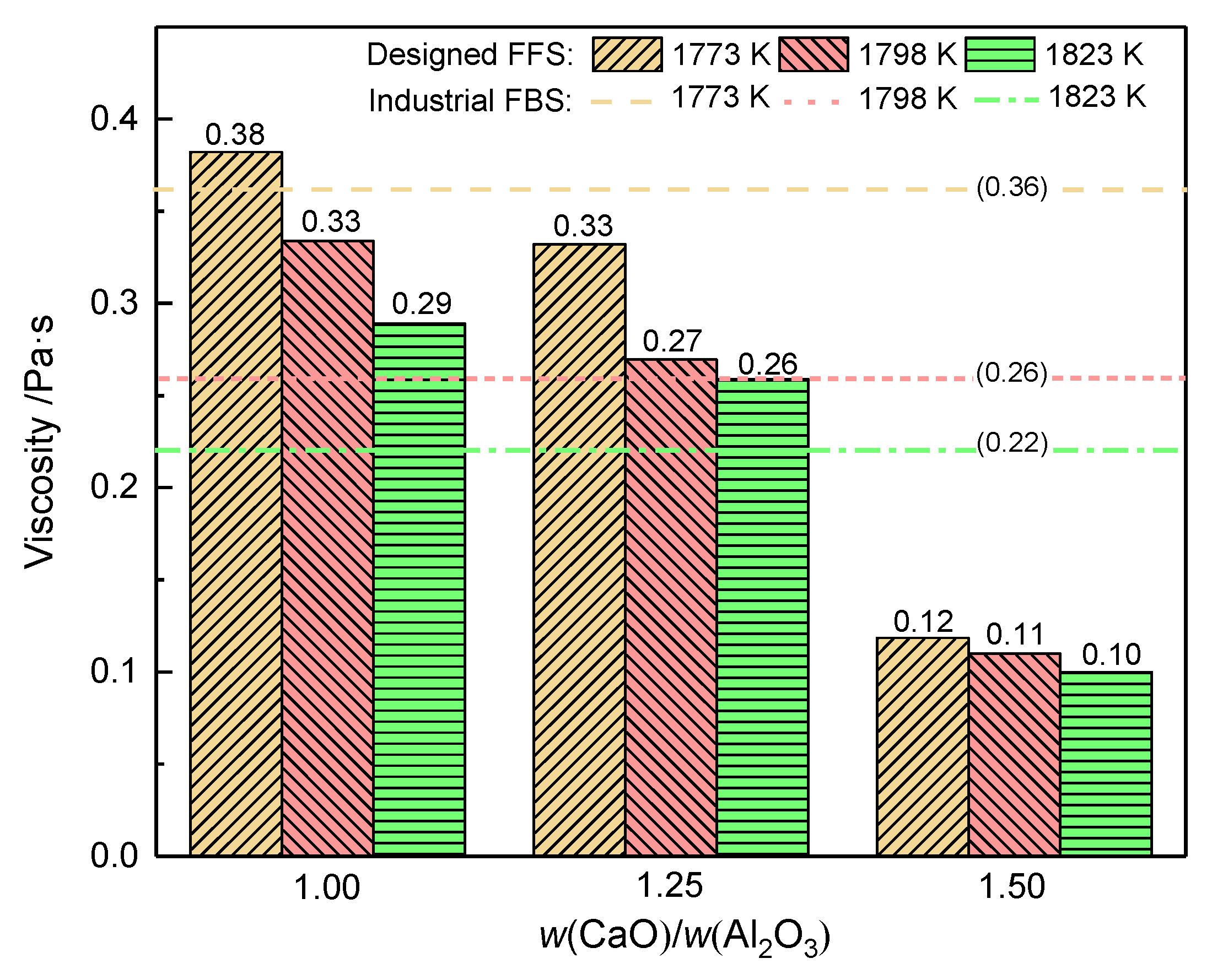
The viscosity of experimental slags with various ratios of w(CaO)/w(Al2O3) was summarized in Figure 10. As shown in Figure 10, the viscosity shows an increased trend with the decrease of temperature when the ratio of w(CaO)/w(Al2O3) is constant. Results also indicated that the viscosity decreased with the ratio of w(CaO)/w(Al2O3) of slag at the constant temperature. When this ratio increased from 1.00 to 1.50, the viscosity decreased from 0.29 Pa·s to 0.10 Pa·s. The explanation of this phenomenon is attributed to that more free oxygen was introduced into the molten slag with increasing w(CaO)/w(Al2O3) [38]. It has been reported that the (AlO4)5− tetrahedron is a main network former, and free oxygen can disrupt the network structure of molten slag by cutting off the bridging oxygen bond, and thereby decreases the slag viscosity [7]. In addition, it can be found that the viscosity of FFS was less than or proximately equal to the industrial FBS when the ratio of w(CaO)/w(Al2O3) was 1.25 or 1.50 and gave the opposite result when the ratio was 1.00 in the same temperature conditions.
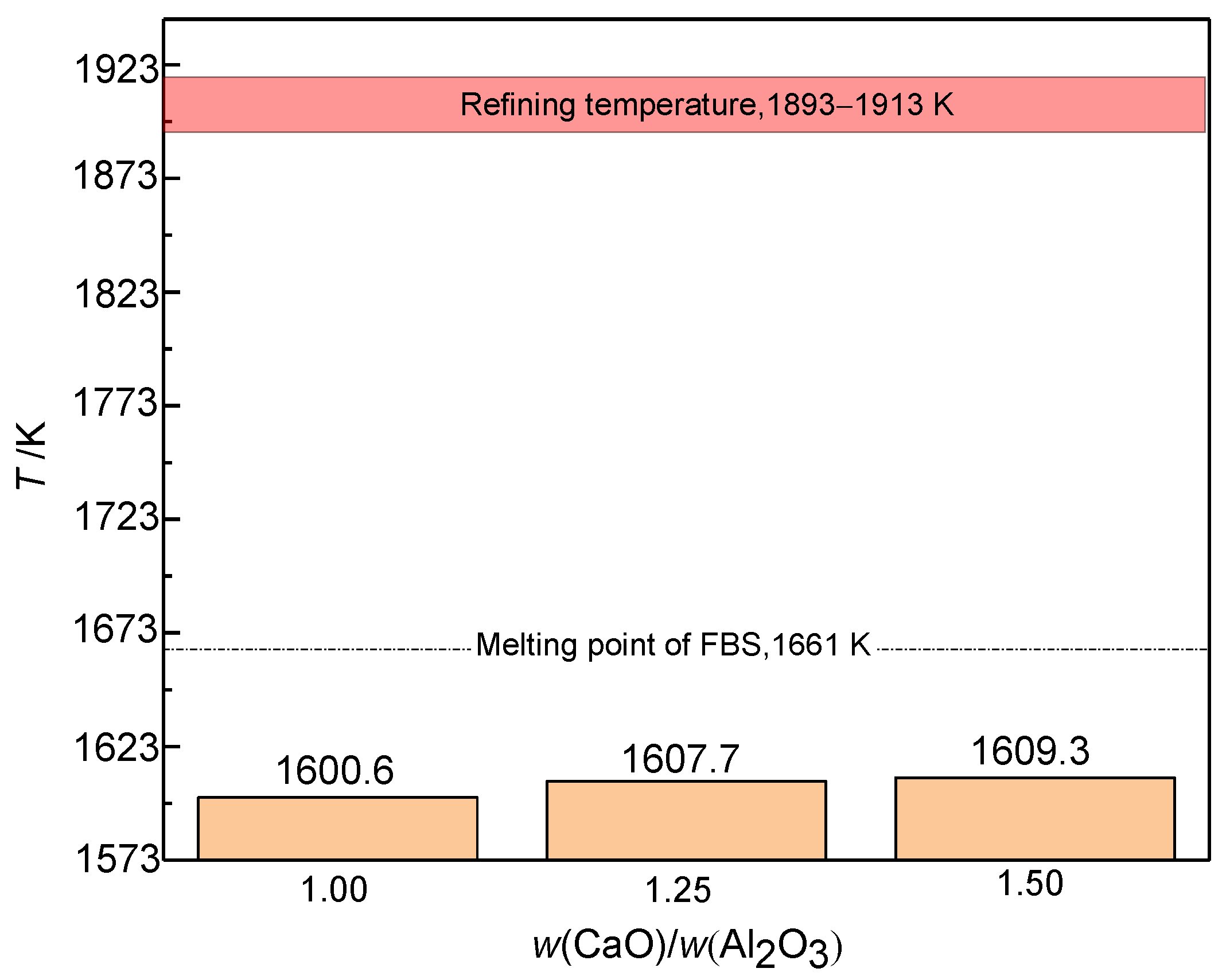
Figure 11 shows the melting point of slags with various ratios of w(CaO)/w(Al2O3). It can be observed that when the ratios of w(CaO)/w(Al2O3) of slag increases from 1.25 to 1.50, the melting point increases less than 2 K. Moreover, the melting point of FFS was much lower than that of industrial FBS and the actual refining temperature (1893–1913 K). It can be speculated that the melting property of the designed FFS in the LF process may be better than the currently used FBS. Therefore, the w(CaO)/w(Al2O3) in FFS was further optimized to 1.25–1.50.
According to the laboratory results, the optimal composition range of components of FFS is w(CaO) = 40–55 wt.%, w(SiO2) = 2–6 wt.%, w(Al2O3) = 30–40 wt.%, w(MgO) = 6–8 wt.%, and w(CaO)/w(Al2O3) = 1.25–1.50.

3.3. Industrial Scale Tests

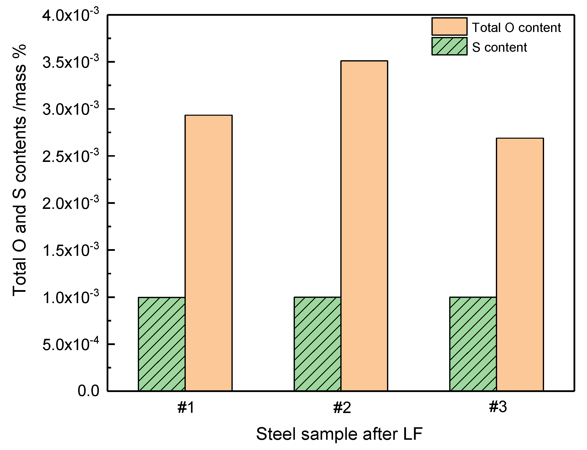
Steel samples were obtained using three kinds of slag. The three types of slags are the chemical composition of slag that is within (No. #1) and not (No. #2) in the optimized range and fluorine-containing slag (No. #3) obtained from axle steel plant (Stainless Steel Co., Ltd., Taiyuan, China), respectively. The compositions of slags correspond to Table 2. The total oxygen and sulphur contents in different steel samples after the LF process are shown in Figure 12. It can be concluded that the FFS (#1 and #2) have a similar desulphurizing capacity as FBS (#3). According to the product standard of the plant, the S content of axle steel should not be higher than 0.001 wt.%. Thus, the desulphurizing capacities of all three refining slags meet the requirement. Furthermore, the total O content in the steel sample controlled by optimized FFS (#1) was slightly higher than FBS (#3), while for steel sample #2 was much higher than for #1 and #3. The main reason for this is that the CaO content and w(CaO)/w(Al2O3) of #2 slag are higher than for #1, which may negatively affect the melting performance and fluidity [39]. Therefore, the results show that optimized FFS can replace FBS, which reduces the risk of environmental pollution while ensuring the smelting performance.
Morphology and chemical composition of inclusions in the steel samples before and after the implementation of the LF process were investigated by SEM-EDS, and the results are shown in Figure 13 and Table 4. The shape of the inclusions in the original LF is, in Figure 13a,b, seen to be angular. The EDS results indicate that the inclusions were mainly Al2O3 as a result of melt deoxidation by Al, and a small amount of magnesium aluminum spinel. The Al2O3 inclusions were generally <3 μm, while the size of magnesium aluminum spinel inclusions was generally 2–6 μm. The inclusions in the steel samples after the LF process changed to MgO-Al2O3 and CaO-MgO-Al2O3 system phases (cf. Figure 13c,d), which were formed by chemical reactions between MgO, CaO, and Al2O3 during the refining process [40,41]. In addition, inclusions will decrease the steel quality from multiple aspects. The most evident factor that affects fatigue property is the inclusion size. The average size of inclusions in the steel sample is ~2–6 μm, which is much lower than the size observed near the fatigue crack initiation site (12.5–33.2 μm) [42].

4. Conclusions

To avoid the use of CaF2 in LF slag in the production of axle steel in the future, a fluorine-free refining slag (FFS) was designed through theoretical analysis and laboratory test. The effects of MgO, SiO2, and w(CaO)/w(Al2O3) on the physical and metallurgical properties of the slag were also studied. Based on the theoretical analysis, it is beneficial to protect the furnace lining and prevent the aluminum dissolved in the melt from oxidizing on the condition of w(SiO2) = 2–10 wt.% and w(MgO) = 6–8 wt.%, respectively. By integrating theoretical analysis and laboratory test, the results showed that for designing an appropriate slag, the range of components of FFS should be w(CaO) = 40–55 wt.%, w(SiO2) = 2–6 wt.%, w(Al2O3) = 30–40 wt.%, w(MgO) = 6–8 wt.%, and w(CaO)/w(Al2O3) = 1.25–1.50. Industrial scale test results demonstrated that the designed FFS has similar deoxidation and desulfurization capabilities as industrial fluorine-bearing refining slag (FBS) and that it therefore meets the requirements for treating axel steel. Use of the designed FFS could protect the environment from fluorine pollution in the LF process of axle steel making.

Author Contributions

Conceptualization and methodology, Q.Z. and L.S.; investigation, L.G., resources, J.Z. and Z.W.; writing—original draft preparation, X.M.; writing—review and editing, R.Z., H.S. and Q.Z. All authors have read and agreed to the published version of the manuscript.

Funding

This research was funded by the National Natural Science Foundation of China grant number 52074078, the National Key Research and Development Program of China grant number 2017YFB0304603, the Liaoning Provincial Natural Science Foundation of China grant number 2019–MS–127, and the Fundamental Research Funds for the Central Universities grant number N2125034 and N2025035.

Institutional Review Board Statement

Not applicable.

Informed Consent Statement

Not applicable.

Data Availability Statement

This study did not report any data and excludes this statement.

Conflicts of Interest

The authors declare no conflict of interest.

Abbreviations

The following abbreviations are used in this manuscript:
FBSFluorine-bearing refining slag
FFSFluorine-free ladle furnace slag
EMUElectric multiple unit
EAFElectric arc furnace
LFLadle furnace
VDVacuum degassing
RHRuhrstahl-Heraeus process
CCContinuous casting
SEMScanning electron microscope
EDSEnergy disperse spectroscopy

References

  1. Li, S.X. Effects of inclusions on very high cycle fatigue properties of high strength steels. Int. Mater. Rev. 2012, 57, 92–114. [Google Scholar] [CrossRef]
  2. Jiang, M.; Wang, X.H.; Chen, B.; Wang, W.J. Laboratory study on evolution mechanisms of non-metallic inclusions in high strength alloyed steel refined by high basicity slag. ISIJ Int. 2010, 50, 95–104. [Google Scholar] [CrossRef] [Green Version]
  3. Reis, B.H.; Bielefeldt, W.V.; Vilela, A.C.F. Efficiency of inclusion absorption by slags during secondary refining of steel. ISIJ Int. 2014, 54, 1584–1591. [Google Scholar] [CrossRef] [Green Version]
  4. Shin, J.H.; Park, J.H. Effect of CaO/Al2O3 ratio of ladle slag on formation behavior of inclusions in Mn and V alloyed steel. ISIJ Int. 2018, 54, 1584–1591. [Google Scholar]
  5. Cheng, P.C.; Huang, S.G.; Pandelaers, L.; Dyck, J.V.; Guo, M.X. Effect of the CaO-Al2O3-Based top slag on the cleanliness of stainless steel during secondary metallurgy. Metall. Mater. Trans. B 2013, 44, 1105–1119. [Google Scholar]
  6. Wu, L.S.; Gran, J.; Sichen, D. The Effect of calcium fluoride on slag viscosity. Metall. Mater. Trans. B 2011, 42, 928–931. [Google Scholar] [CrossRef]
  7. Jie, Q.; Liu, C.J.; Jiang, M.F. Properties investigation of CaO-Al2O3-SiO2-Li2O-B2O3-Ce2O3 mould flux with different w(CaO)/w(Al2O3) for heat-resistant steel continuous casting. Can. Metall. Q. 2017, 56, 212–220. [Google Scholar]
  8. Seetharaman, S.; Mukai, K.; Sichen, D. Viscosities of slags—An overview. Steel Res. Int. 2005, 76, 267–278. [Google Scholar] [CrossRef]
  9. Ohta, M.; Kubo, T.; Morita, K. Effects of CaF2, MgO and SiO2 addition on sulfide capacities of the CaO-Al2O3 slag. Tetsu-to-Hagane 2013, 89, 742–749. [Google Scholar] [CrossRef] [Green Version]
  10. Guo, B.Q.; Bao, Y.P.; Wang, M.; Lin, L. Optimization of CaO- SiO2-Al2O3-MgO-CaF2 refining slag in low-carbon and aluminum-containing 20Mn2 steel. Chin. J. Eng. 2015, 37, 1415–1421. [Google Scholar]
  11. Park, J.H.; Min, D.J.; Song, H.S. The Effect of CaF2 on the viscosities and structures of CaO-SiO2(-MgO)-CaF2 slags. Metall. Mater. Trans. B 2002, 33, 723–729. [Google Scholar] [CrossRef]
  12. Peng, K.W.; Zhang, P.J.; Xie, G.H.; Ma, L. Study on properties of Al2O3 –CaO-Na2CO3 slag system. Appl. Mech. Mater. 2011, 269, 117–119. [Google Scholar]
  13. Liu, C.J.; Zhang, R.; Zhao, X.B.; Jia, J.X.; Min, Y. Quantification of phosphorus structures in CaO-SiO2-P2O5 glasses via raman spectroscopy. J. Non-Cryst. Solids 2020, 557, 1–9. [Google Scholar] [CrossRef]
  14. Zhang, X.B.; Liu, C.J.; Jiang, M.F. Effect of fluorine on melt structure for CaO-SiO2-CaF2 and CaO-Al2O3-CaF2 by molecular dynamics simulations. ISIJ Int. 2020, 60, 2176–2182. [Google Scholar] [CrossRef]
  15. Persson, M.; Seetharaman, S.; Seetharaman, S. Kinetic Studies of Fluoride Evaporation from Slags. ISIJ Int. 2007, 12, 1711–1717. [Google Scholar] [CrossRef] [Green Version]
  16. Zhao, Z.; Zhao, J.; Tan, Z.; Qu, B.; Cui, Y.R. The volatilization behaviour of typical fluorine-containing slag in steelmaking. Soc. Open Sci. 2020, 7, 1–8. [Google Scholar] [CrossRef]
  17. Mao, H.X.; Hu, H.T.; Ma, G.J. Contamination of fluorine in CC mould powder to environment and countermeasures. Steelmaking 1999, 15, 41–45. [Google Scholar]
  18. Wang, W.L.; Cai, D.; Zhang, L. A review of fluorine-free mold flux development. ISIJ Int. 2018, 58, 1957–1964. [Google Scholar] [CrossRef] [Green Version]
  19. Zheng, K.; Zhang, Z.T.; Liu, L.L.; Wang, X.D. Investigation of the viscosity and structural properties of CaO-SiO2-TiO2 slags. Metall. Mater. Trans. B 2014, 45, 1389–1397. [Google Scholar] [CrossRef]
  20. Gao, J.X.; Wen, G.H.; Sun, Q.H.; Tang, P.; Liu, Q. The Influence of Na2O on the solidification and crystallization behavior of CaO-SiO2-Al2O3-based mold flux. Metall. Mater. Trans. B 2015, 46, 1850–1859. [Google Scholar] [CrossRef]
  21. Tang, Z.F.; Qiao, J.L.; Jiang, X.Y. Kinetics of Na2O evaporation from CaO-Al2O3-SiO2-MgO-TiO2-Na2O slags. Ironmak. Steelmak. 2017, 44, 237–245. [Google Scholar] [CrossRef]
  22. Wu, C.C.; Cheng, G.G.; Long, H. Effect of Ce2O3 and CaO/Al2O3 on the Phase, melting temperature and viscosity of CaO-Al2O3-10 mass% SiO2 based slags. High Temp. Mater. Processes. High Temp. Mater. Process. 2013, 33, 77–84. [Google Scholar] [CrossRef]
  23. Keshari, B.K.K.; Kumar, S.; Roy, S.; Pratihar, T.K. Optimising slag composition & gas purging in a LF to reduce noise and improve refining. Steel Times Int. 2012, 36, 17–19. [Google Scholar]
  24. Xu, J.F.; Zhang, J.Y.; Jie, C.; Ruan, F.; Chou, K.C. Experimental measurements and modelling of viscosity in CaO-Al2O3-MgO slag system. Ironmak. Steelmak. 2011, 38, 329–337. [Google Scholar] [CrossRef]
  25. Hai, F.; Wang, C.X.; Zhang, J.M.; Qie, J.C. Development trends of environmental protection technologies for Chinese steel industry. J. Iron Steel Ress. Int. 2017, 24, 235–242. [Google Scholar]
  26. Wang, Y.; Wen, Z.; Cao, X. Environmental efficiency evaluation of China’s iron and steel industry: A process -level data envelopment analysis. Sci. Total Environ. 2020, 707, 1–52. [Google Scholar] [CrossRef]
  27. Ökvist, L.S. The melting properties of tuyere slags with and without flux injection into the blast furnace. ISIJ Int. 2001, 41, 1429–1436. [Google Scholar] [CrossRef] [Green Version]
  28. Mills, K.C. Slag Atlas, VDEh, 2nd ed.; Verlag Stahleisen GmbH: Düsseldorf, Germany, 1995. [Google Scholar]
  29. Almeida, R.A.M.; Vieira, D.; Bielefeldt, W.V.; Vilela, A.C.F. MgO saturation analisys of CaO-SiO2-FeO-MgO-Al2O3 slag system. Mater. Res. 2017, 21, 1–8. [Google Scholar] [CrossRef]
  30. Zhao, Q.; Zheng, X.; Liu, C.J.; Jiang, M.F.; Saxén, H.; Zevenhoven, R. Corrosion behavior of MgO-C ladle refractory by molten slag. Steel Res. Int. 2020, 92, 2000497. [Google Scholar] [CrossRef]
  31. Dong, Y.; Jiang, Z.; Cao, Y.; Zhang, H.; Shen, H. Effect of MgO and SiO2 on surface tension of fluoride containing slag. J. Cent. South. Univ. 2014, 21, 4104–4108. [Google Scholar] [CrossRef]
  32. Chang, Y.E.; Lin, C.M.; Shen, J.M. Effect of MgO content on the viscosity, foaming life, and bonding in liquid and liquid/Solid CaO-SiO2-MgO-5Al2O3-30FeO slags. Met.—Open Access Metall. J. 2021, 11, 249. [Google Scholar] [CrossRef]
  33. Kim, H.; Kim, W.H.; Sohn, I.; Min, D.J. The effect of MgO on the viscosity of the CaO-SiO2-20 wt%Al2O3-MgO slag system. Steel Res. Int. 2010, 81, 261–264. [Google Scholar] [CrossRef]
  34. Vázquez, A.B.; Caballero, A.; Pena, P. Quaternary System Al2O3-CaO-MgO-SiO2: II Study of the Crystallization Volume of MgAl2O4. J. Am. Ceram. Soc. 2005, 88, 1949–1957. [Google Scholar] [CrossRef]
  35. Song, M.; Shu, Q.; Sichen, D. Viscosities of the quaternary Al2O3-CaO-MgO-SiO2 slags. Steel Res. Int. 2010, 82, 260–268. [Google Scholar] [CrossRef]
  36. Liu, Y.; Lv, X.; Li, B.; Bai, C. Relationship between structure and viscosity of CaO-SiO2-MgO-30.00 wt.%Al2O3 slag by molecular dynamics simulation with FT-IR and Raman spectroscopy. Ironmak. Steelmak. 2017, 45, 1–11. [Google Scholar] [CrossRef]
  37. Liao, J.L.; Zhang, Y.Y.; Sridhar, S. Effect of Al2O3/SiO2 ratio on the viscosity and structure of slags. ISIJ Int. 2012, 52, 753–758. [Google Scholar] [CrossRef] [Green Version]
  38. Zhang, R.; Min, Y.; Wang, Y.; Zhao, X.; Jia, X.J.; Liu, C. Viscosity estimation of multicomponent slags of CaOSiO2-Al2O3-FexO system based on microstructure analysis. Energy Fuel. 2020, 34, 1–40. [Google Scholar]
  39. Liang, X. Effect of additives on melting point and viscosity of rh refining slag. Open Mater. Sci. J. 2011, 5, 9–14. [Google Scholar] [CrossRef] [Green Version]
  40. Yang, G.G.; Wang, X.H. Inclusion evolution after calcium addition in low carbon Al-Killed steel with ultra low sulfur content. ISIJ Int. 2015, 55, 126–133. [Google Scholar] [CrossRef] [Green Version]
  41. Liu, C.; Gao, X.; Ueda, S. Change in Composition of inclusions through the reaction between Al-killed steel and the slag of CaO and MgO Saturation. ISIJ Int. 2019, 59, 268–276. [Google Scholar] [CrossRef] [Green Version]
  42. Gu, C.; Wang, M.; BaO, Y.P.; Wang, F.M.; Lian, J.H. Quantitative Analysis of Inclusion Engineering on the Fatigue Property Improvement of Bearing Steel. Metal 2019, 9, 476. [Google Scholar] [CrossRef] [Green Version]
Figure 1. Isothermal cross-section diagrams of CaO-Al2O3-SiO2-MgO system at 1873 K with different MgO contents (a) 5 wt.%, (b) 6 wt.%, (c) 7 wt.%, (d) 8 wt.%, (e) 9 wt.%, and (f) 10 wt.%.
Metals 11 01973 g001
Figure 2. Liquid phase area diagrams of CaO-Al2O3-SiO2-MgO system with different MgO contents (a) 5 wt.%, (b) 6 wt.%, (c) 7 wt.%, (d) 8 wt.%, (e) 9 wt.%, and (f) 10 wt.%.
Metals 11 01973 g002
Figure 3. Liquid phase area diagrams of CaO-Al2O3-MgO-SiO2 system with different SiO2 contents (a) 2 wt.%, (b) 6 wt.%, (c) 10 wt.%, and (d) 14 wt.%.
Metals 11 01973 g003
Figure 4. Iso-activity diagram of SiO2 in CaO-Al2O3-SiO2-10 wt.% MgO system at 1873 K, where the data was selected from the Slag Atlas (black solid lines) and the FactSage 7.1 software database (red solid lines).
Metals 11 01973 g004
Figure 5. Pseudo ternary phase diagram of CaO-Al2O3-SiO2-10 wt.% MgO.
Metals 11 01973 g005
Figure 6. Iso-activity diagrams of (a) Al2O3 and (b) CaO in the CaO-Al2O3-SiO2-10 wt.% MgO quaternary system at 1873 K, where the data was selected from the Slag Atlas (black solid lines) and the FactSage 7.1 software database (blue solid lines).
Metals 11 01973 g006
Figure 7. Viscosity-temperature curves of the experimental slags.
Metals 11 01973 g007
Figure 8. Viscosity-temperature histogram of slags with different SiO2 contents.
Metals 11 01973 g008
Figure 9. Melting point of slags with different SiO2 contents.
Metals 11 01973 g009
Figure 10. Viscosity-temperature histogram of slags with various ratios of w(CaO)/w(Al2O3).
Metals 11 01973 g010
Figure 11. Melting point of slags with various ratios of w(CaO)/w(Al2O3).
Metals 11 01973 g011
Figure 12. Total O and S contents in different steel samples after the LF process.
Metals 11 01973 g012
Figure 13. SEM images of typical inclusion morphology of steel samples (a,b) early in and (c,d) after the LF process, which (a,b) were obtained from different areas within the same sample, same as (c,d).
Metals 11 01973 g013
Table 1. Chemical compositions of experimental slags (wt.%).
No.CaOAl2O3SiO2MgOCaF2w(CaO)/w(Al2O3)
146.1136.8910.007.00-1.25
248.3338.676.007.00-1.25
350.5640.442.007.00-1.25
443.5043.506.007.00-1.00
552.2034.806.007.00-1.50
655.0730.911.847.185.001.78
Table 2. Chemical compositions of the slag for industrial scale tests (wt.%).
No.CaOAl2O3SiO2MgOCaF2w(CaO)/w(Al2O3)
#153.5437.313.725.43-1.44
#257.5031.187.104.22-1.84
#355.1530.011.847.185.821.84
Table 3. Composition requirement of axle steel (wt.%).
CSiMnPSCrMoNiVAlCu
0.24–0.320.20–0.400.60–0.90≤0.01≤0.010.90–1.200.20–0.300.50–1.50≤0.060.01–0.04≤0.20
Table 4. Inclusion composition in SEM images (atomic%).
PointAlOMgCa
+127.9672.04--
+225.9564.0310.02-
+38.2946.1244.451.15
+43.8645.8650.30-
+525.2755.854.4014.77
Publisher’s Note: MDPI stays neutral with regard to jurisdictional claims in published maps and institutional affiliations.