Article

Numerical Analysis of Particle Trajectories in a Gas–Powder Jet during the Laser-Based Directed Energy Deposition Process

by
Stanislav Stankevich
*,
Nikolay Larionov
and
Ekaterina Valdaytseva
World-Class Research Center, “Advanced Digital Technologies”, State Marine Technical University, 190121 Saint Petersburg, Russia
*
Author to whom correspondence should be addressed.
Metals 2021, 11(12), 2002; https://doi.org/10.3390/met11122002
Submission received: 30 October 2021 / Revised: 4 December 2021 / Accepted: 6 December 2021 / Published: 11 December 2021
(This article belongs to the Special Issue Laser Processing of Metals and Alloys)

Abstract

:
Based on numerical solutions of the equation of motion of a particle in a gas jet modeled by the Reynolds-averaged Navier–Stokes equations, the features of transporting powder particles to the working zone of laser-based directed energy deposition are investigated. The propagation of a gas jet in a confined space in the presence of obstacles in the form of a substrate and a wall of a part is considered. A solution determining the gas-dynamic parameters of the jet is obtained, and the results of calculating its velocity field are presented. The influence of gas-dynamic parameters on the trajectories of the powder particles is analyzed. It is shown that these parameters determine the amount of model material involved in the formation of the geometry of the part.

1. Introduction

Laser-based directed energy deposition (L-DED) is an actively developing additive technology [1] that has been successfully introduced into the modern production cycles of metal alloy products [2,3,4,5] and also allows for the repair of worn surfaces of parts [6,7] or the application of special coatings on products [8]. Despite several advantages over traditional methods of manufacturing and surfacing, the technology is complex, with many technological parameters that affect both the properties of the product and the economic indicators of its manufacture. L-DED is a multiphysical process with several problems, such as heat transfer and heating, hydrodynamics and gas dynamics, thermal capillary effect, diffusion, and mass transfer. The technological parameters of the traverse speed and the powder feed rate strongly affect the height [9] and width [10] of the deposited layer, which determine the size of the melt bath and affect the hydrodynamic stability. The hydrodynamic stability of the process, in turn, affects the surface quality of the manufactured product [11]. To optimize economic indicators, an important aspect is the powder capture efficiency (PCE). The meaning of this efficiency lies in the amount of material involved directly in the formation of the product. Ideally, the PCE should be 1, but in practice, it can fluctuate on average from 0.3 to 0.8. Such a spread of PCE is caused by the design of gas–powder nozzles, the roughness of transport channels, and the sphericity of the model material.
In connection with the above, it is clear that the development of an adequate physical model to describe a gas–powder jet in a space with different geometries caused by the walls of the nozzle or the substrate is necessary both to optimize the parameters of the gas–powder mixture supply and to optimize the design of technological nozzles.
To date, there are many works aimed at studying the gas–powder phenomena in L-DED. Some of these works focus on numerical calculations [12,13,14], and others offer analytical versions of models [15]. The most common research tool is computational fluid dynamics (CFD), which is self-sufficient in the case when the system under study can be represented as a two-fluid model [16].
However, sometimes, more information is needed about the movement of individual particles in the carrier gas. In this case, the Euler–Lagrange model is used, in which information about the motion of individual particles is obtained as a result of integrating the equations of motion of particles in a known velocity field of the carrier gas [16,17,18]. The works [19,20,21,22,23] can be noted here, in which, in particular, the difference between the velocity of the powder particles and the gas flow velocity is shown, due to both the properties of the powder and its sphericity.
Another important factor affecting the trajectory of particles is collisions with the walls of the transporting path, as well as with obstacles in the form of a wall or a substrate. Taking into account energy losses when particles interact with walls or obstacles is necessary for more accurate particle tracing.
In the presented paper, the transportation of powder particles by the carrier gas to the working zone of direct laser cultivation is considered from the point of view of the Euler–Lagrange model. The velocity field of the carrier gas in a confined space in the presence of obstacles is calculated using the Navier–Stokes equations averaged by Reynolds together with the turbulence model k-ε. The integration of the equation of motion of a particle in the found velocity field is carried out taking into account the homogeneous gravity field. The main difference from the articles of other authors is the choice of a specific geometry of the space where the gas–powder jet propagates.

2. The Geometry of the L-DED Experiment, Approximations, and the Mathematical Model

2.1. The Geometry of the L-DED Experiment

Usually, two types of nozzles are used in the process of laser-based directed energy deposition: tubular and slit. The fundamental difference is that, in the case of a tubular nozzle, one to eight tubes are used to inject the gas–powder mixture into the working area, depending on the nozzle design. In the case of a slit nozzle, the gas–powder mixture is injected concentrically into the propagation of laser radiation. Since this paper considers a two-dimensional problem, the geometry of the computational domain can be applied to describe both slit and tubular nozzles in the case of the symmetrical arrangement of tubes. By the position of the obstacle, substrate, or wall, we take the intersection point of the axes of the transport channels.
The studied area of the flow of a mixture of transport (argon) and protective (argon) gases includes both (1) the space between the nozzle and the substrate and the substrate itself and (2) the space inside the nozzle. The point of intersection of the axes of the transport channels will be located on the surface of the substrate. The schemes of the systems under study are shown in Figure 1, where the blue arrows indicate the inlet edges and the green arrows indicate the outlet edges, the walls are marked with bold black lines, the axes of the tubes are marked with dotted lines.

2.2. Approximations Used

When describing the propagation of a gas–powder jet in a space with different geometries, we used the following assumptions:
  • Gas flows inside and outside the nozzle are in the approximation of a viscous compressible gas with a Mach number M < 0.3 and modeled by the Navier–Stokes equations averaged by Reynolds together with the turbulence model k-ε.
  • The substrate and the powder material are in the solid state.
  • The powder particles do not interact with each other and have a shape close to spherical.
  • Heating of the gas–powder jet by laser radiation is not considered, and the gas temperature is constant.
  • The effect of laser radiation is taken into account indirectly through the melt pool, into which the powder particles “freeze”.
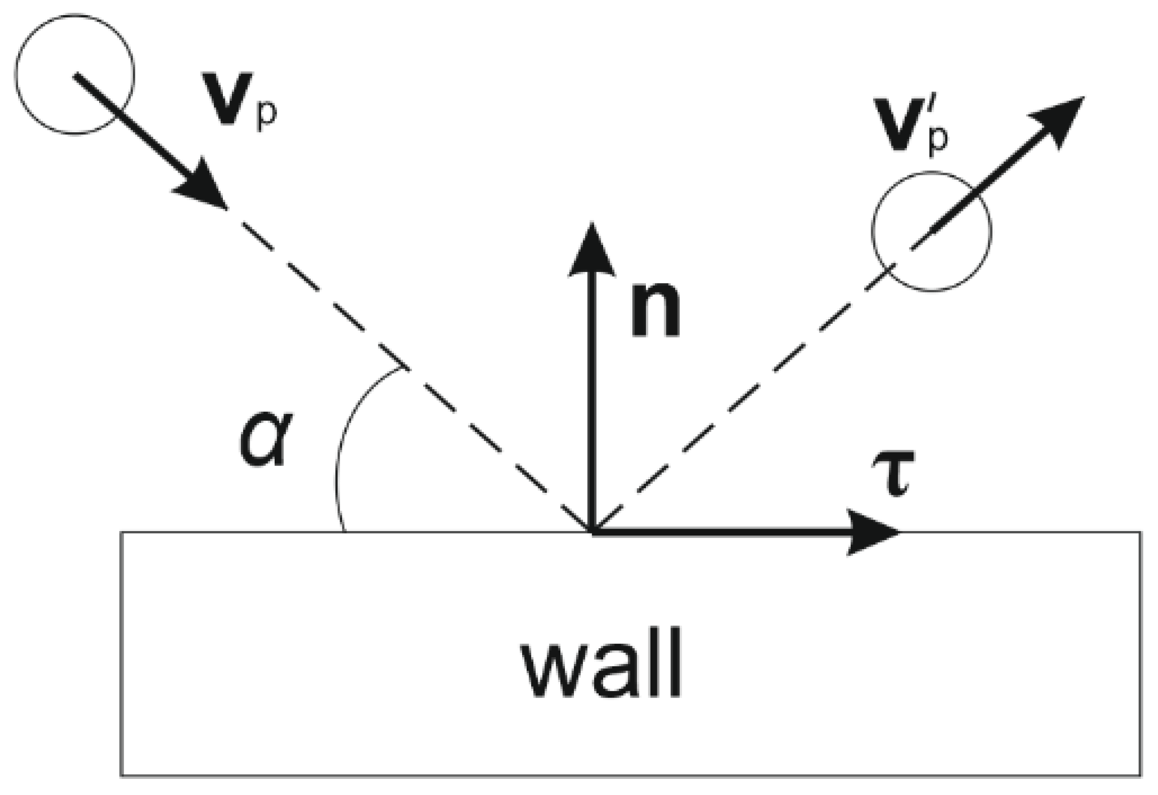
  • The trajectories of powder particles are caused by the presence of only three forces: the Stokes force, adjusted for the case of gas movement; the force of interaction when particles collide with obstacles; and gravity.

2.3. Mathematical Model: Description of the Mixture Flow

As noted above, our calculations will be based on the Euler–Lagrange model. If we estimate the Reynolds number (Re) using the cross section of the transport channel, the viscosity of the gas, and its characteristic velocity, we get a number on the order of 103, i.e., the gas flow can be turbulent. Therefore, to describe the flow of a mixture of protective and transport gases, we use the Navier–Stokes equation averaged by Reynolds (Reynolds equation; Reynolds-averaged Navier–Stokes (RANS)), together with the turbulence model k-ε [24]. Let us write out the equations solved in this case [25].
The continuity equation:
ρ t + · ( ρ u ) = 0 ,
where ρ is the density and u is the vector of the averaged velocity.
The Reynolds equation:
ρ u t + ρ u · u = p + · ( μ ( u + ( u ) T ) 2 3 μ ( · u ) I ) + F + ρ g ,
where p is the pressure; μ is the dynamic viscosity; F is the vector of free forces, T is the transposition operation, I is the unit matrix, and g is the acceleration of gravity.
The turbulent kinetic energy transfer equation k:
ρ k t + ρ u · k = · ( ( μ + μ T σ k ) k ) + P k ρ ε , P k = μ T ( u : ( u + ( u ) T ) 2 3 ( · u ) 2 ) 2 3 ρ k · u ,
where μT is the turbulent viscosity and the operation “:” means the following product of matrices: a : b = n m a n m b n m .
The equation of the turbulent scattering velocity ε:
ρ ε t + ρ u · ε = · ( ( μ + μ T σ ε ) ε ) + C ε 1 ε k P k C ε 2 ρ ε 2 k , μ T = ρ C μ k 2 ε ,
where σ k = 1.0, σ ε = 1.3, C ε 1 = 1.44, C ε 2 = 1.92, and C μ = 0.09 are constants of the model and are determined empirically [26].

2.4. Initial and Boundary Conditions for the Mixture Flow

To solve Equations (1–4), the following initial conditions are adopted: p0 = 0.1 MPa and u0 = 0. The surface roughness for the walls of the gas channels in the nozzle is taken as equal to 0.3 microns and for the substrate as equal to 1.6 microns. The pressure value at the boundaries of the gas source is assumed to be equal to the initial pressure p0. The viscosity value is assumed to be equal to the viscosity of argon at normal conditions.

2.5. Mathematical Model: Equation of Motion of Powder Particles in a Given Gas Flow

The problem of finding the trajectories of powder particles in a given gas flow is reduced to solving the equation of motion
m p d v d t = m p g + F D ,
where m p is the mass of the powder particle, v is the averaged velocity vector of the particle, and g is the acceleration vector of free fall. The force F D describes the viscous forces acting on a powder particle and is determined by Stokes’ law, corrected for the case of a moving flow of a carrier gas:
F D = 18 μ C D R e p 24 ρ p d p 2 · ( u v ) ,
where u is the velocity field of the carrier gas, which is found when solving Equations (1)–(4); d p is the diameter of the particle; ρ p is the density of the particle; and R e p is the Reynolds number for the particle. The drag coefficient of the particle C D is determined from the Haider–Levenspiel model [27], which takes into account the sphericity efficiency of the powder Sp. Let us write out an explicit form of this coefficient:
C D = 24 R e ( 1 + A · R e B ) + C 1 + D / R e ,
where the coefficients A, B, C, and D have the form
A = e x p ( 2.3288 5.4581 · S p + 2 , 4486 · S p 2 ) , B = 0.0964 + 0.5565 · S p , C = e x p ( 4.905 13.8944 · S p + 18.4222 · S p 2 10.2599 · S p 3 ) , D = e x p ( 1.4681 + 12.2584 · S p 20.7322 · S p 2 + 15.8855 · S p 3 ) .
The sphericity efficiency Sp is defined as the ratio of the surface area of the sphere to the surface area of the non-spherical particle under consideration and 0 < Sp ≤1.

2.6. Initial and Boundary Conditions for Particles

The size of the powder particles varies depending on the manufacturer and the brand, but most often, the distribution of the number of particles by fractions is normal. For calculations, a function describing the random size of powder particles with a mathematical expectation of 100 microns is used.
The initial velocity of the powder particles v = k g p · u , where the coefficient k g p expresses the ratio of the velocity of the powder particles to the velocity of the gas flow. This coefficient is empirical and according to various sources can take a value from 0.22 to 0.65 [19,20,21,22,23].
Powder particles collide with the walls of the gas–powder path during transportation. When a particle enters the calculated region, its velocity vector has some deviation from the axis of the gas flow due to multiple ricochets from the walls of the transport channel. The initial velocity of a powder particle can be represented as v p = v + v d , where v d is the vector of random deviation of the powder particle relative to the vector of propagation of the transport gas. The value of v d is determined experimentally.
Ideally, we can consider these collisions as elastic. However, in reality, when particles collide with obstacles, there is a loss of kinetic energy, which affects the speed. To account for losses, we decompose the velocity vector into normal v n = v p · n and tangential v τ = v p · τ components, as shown in Figure 2, and introduce the energy conservation coefficients k n and k τ after a collision. Thus, the velocity vectors of the particle after the collision will take the form v n = v n · k n and v τ = v τ · k τ . The coefficients k n and k τ depend on the angle of incidence α, but for simplicity, we will consider them constant.
The particle sphericity coefficient Sp is assumed to be 0.9.

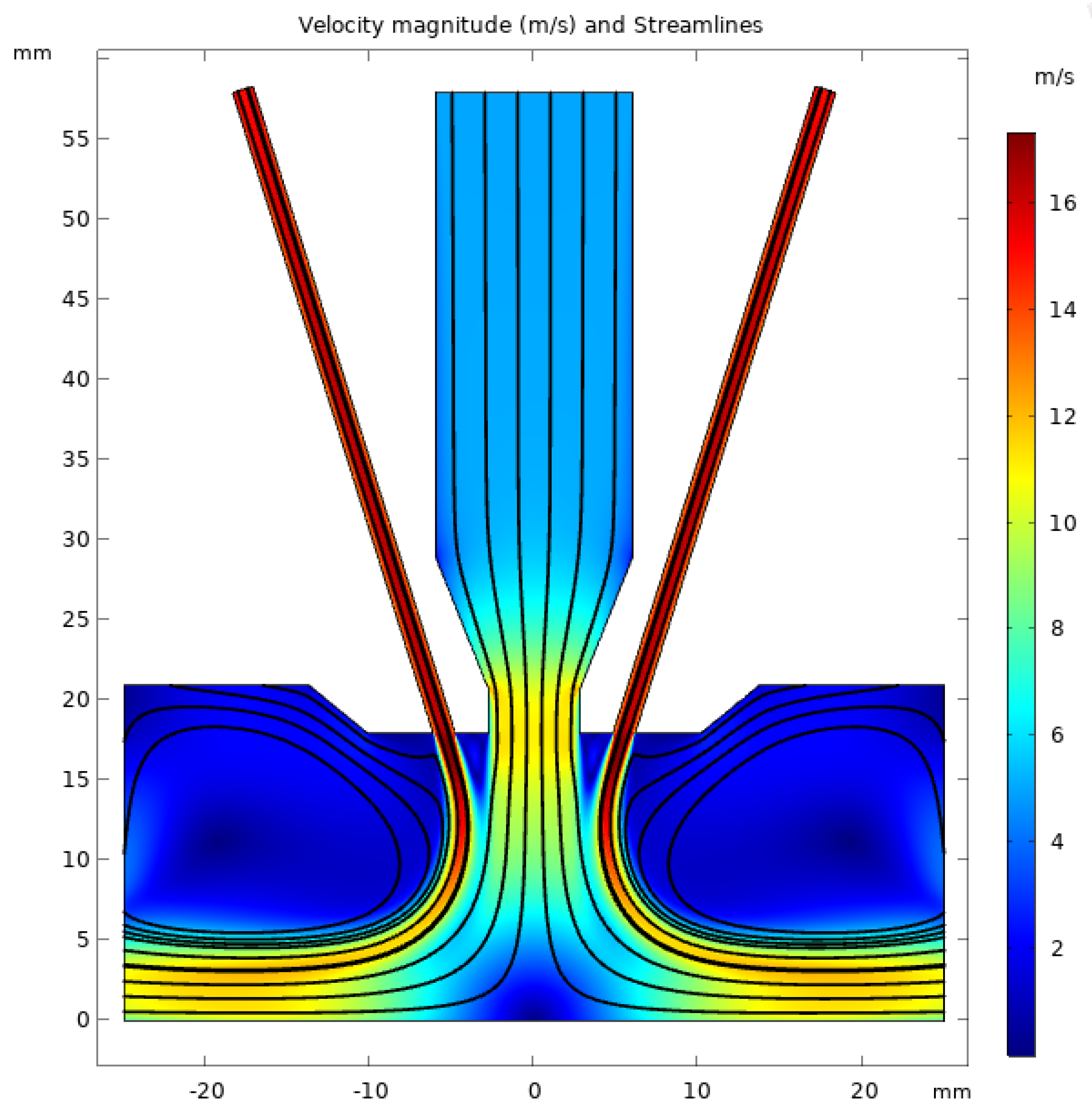
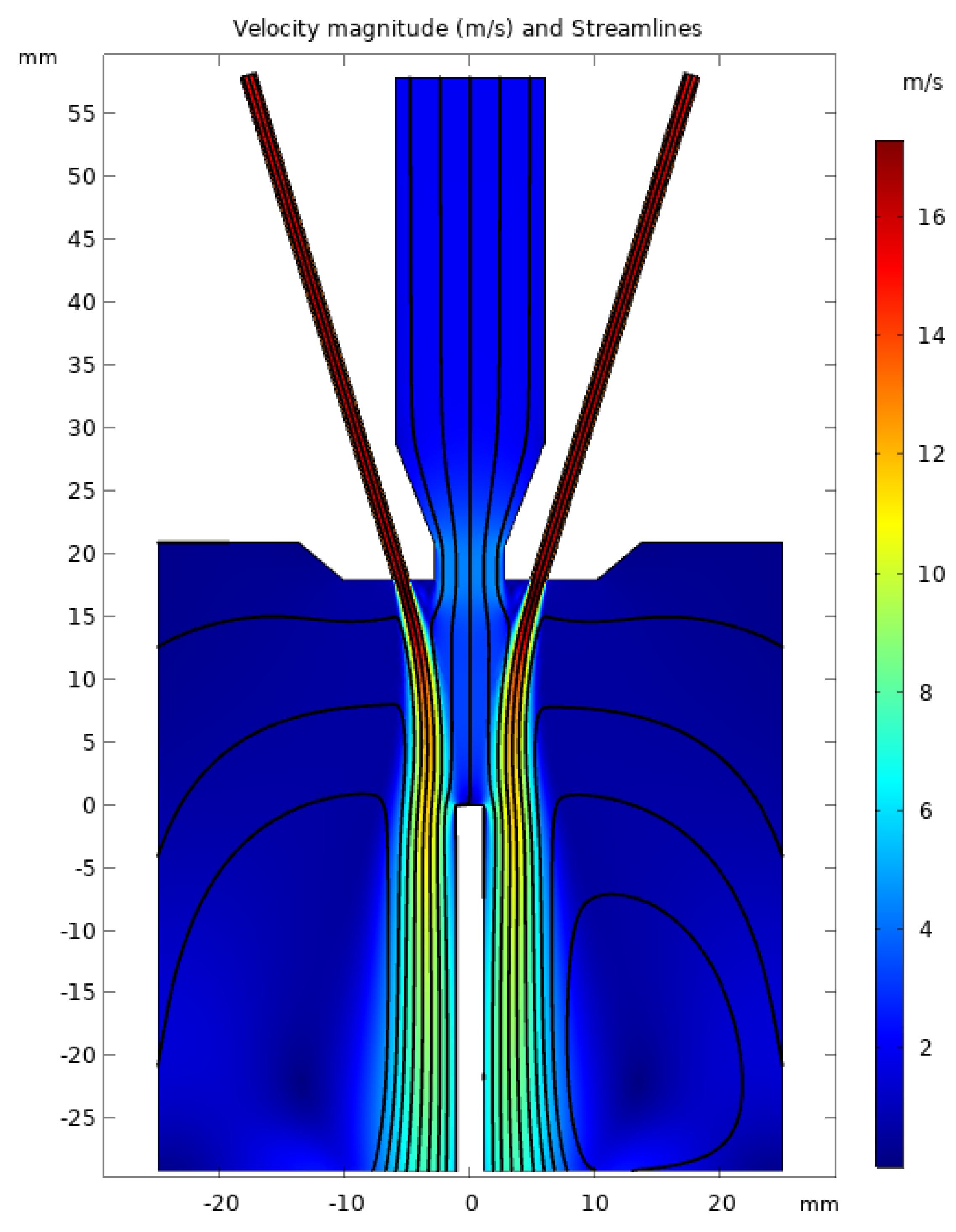
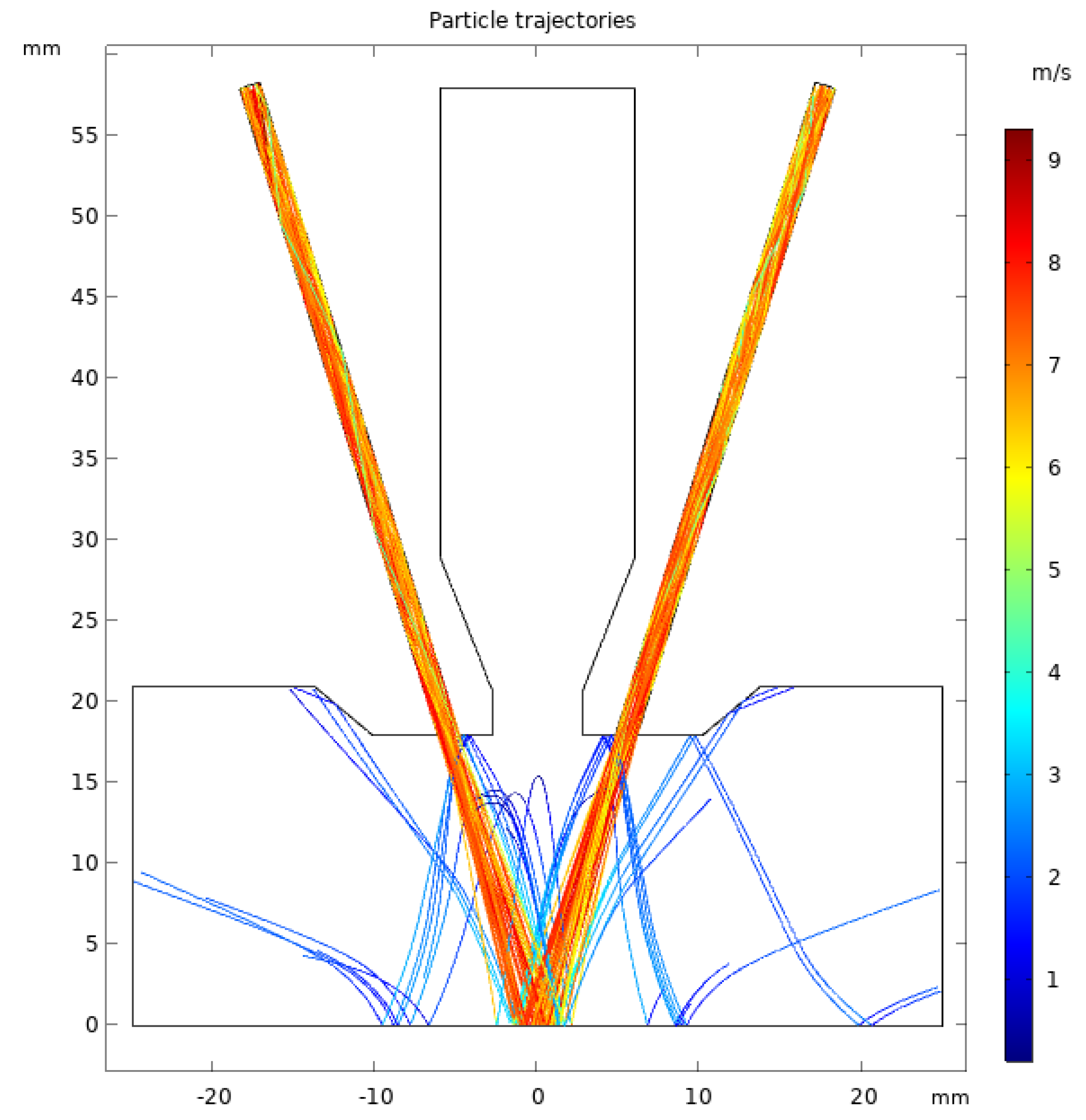
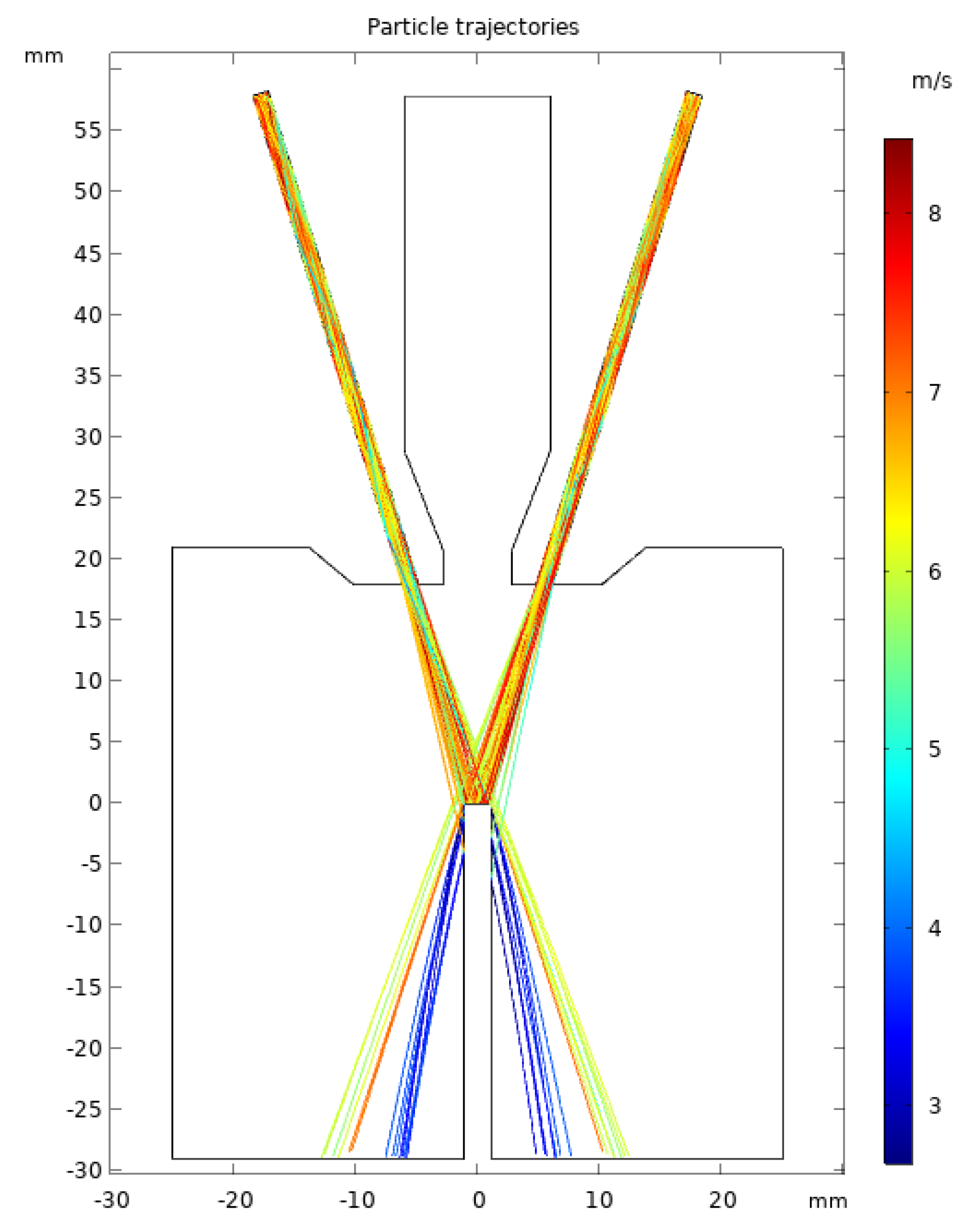
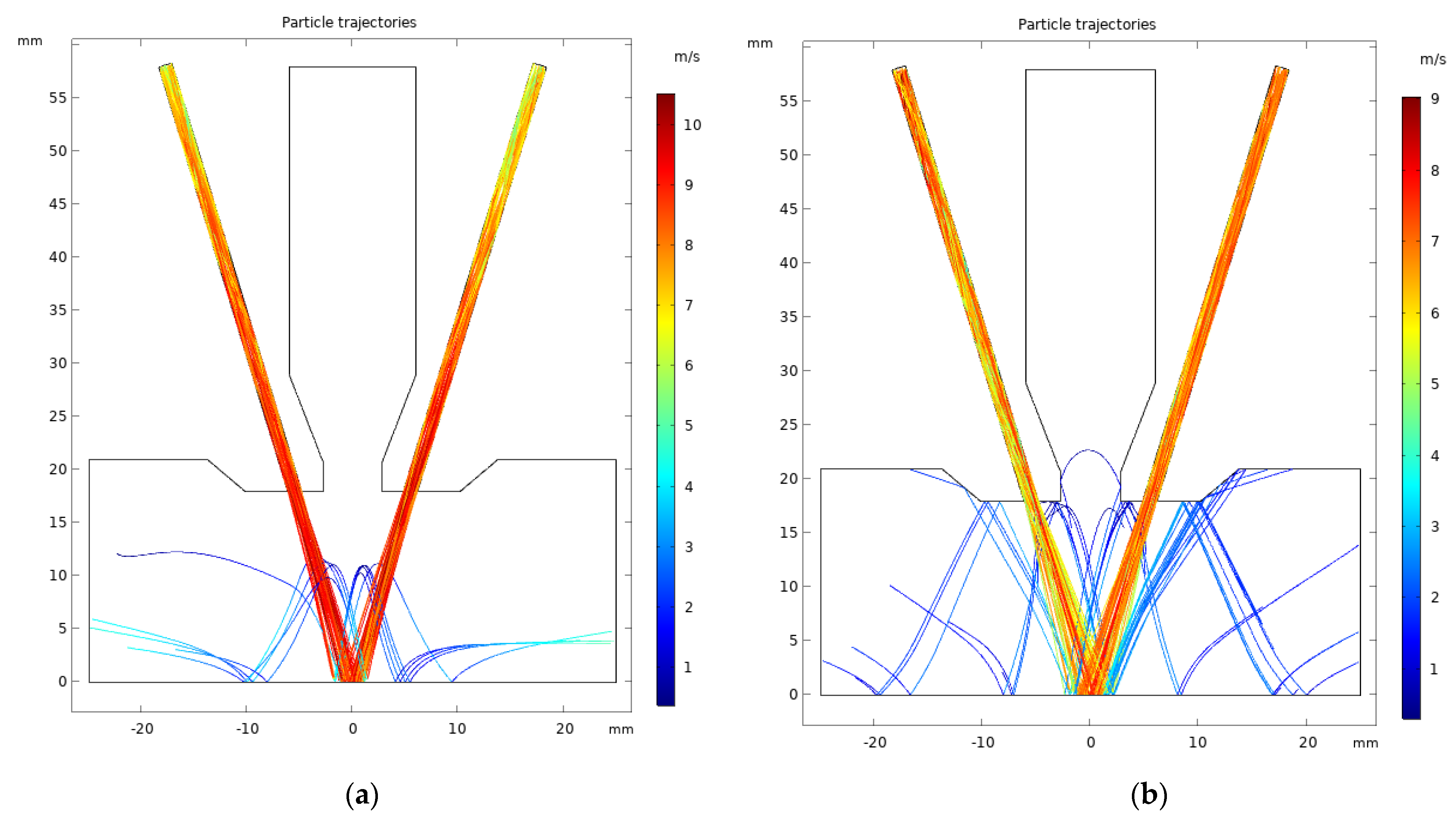
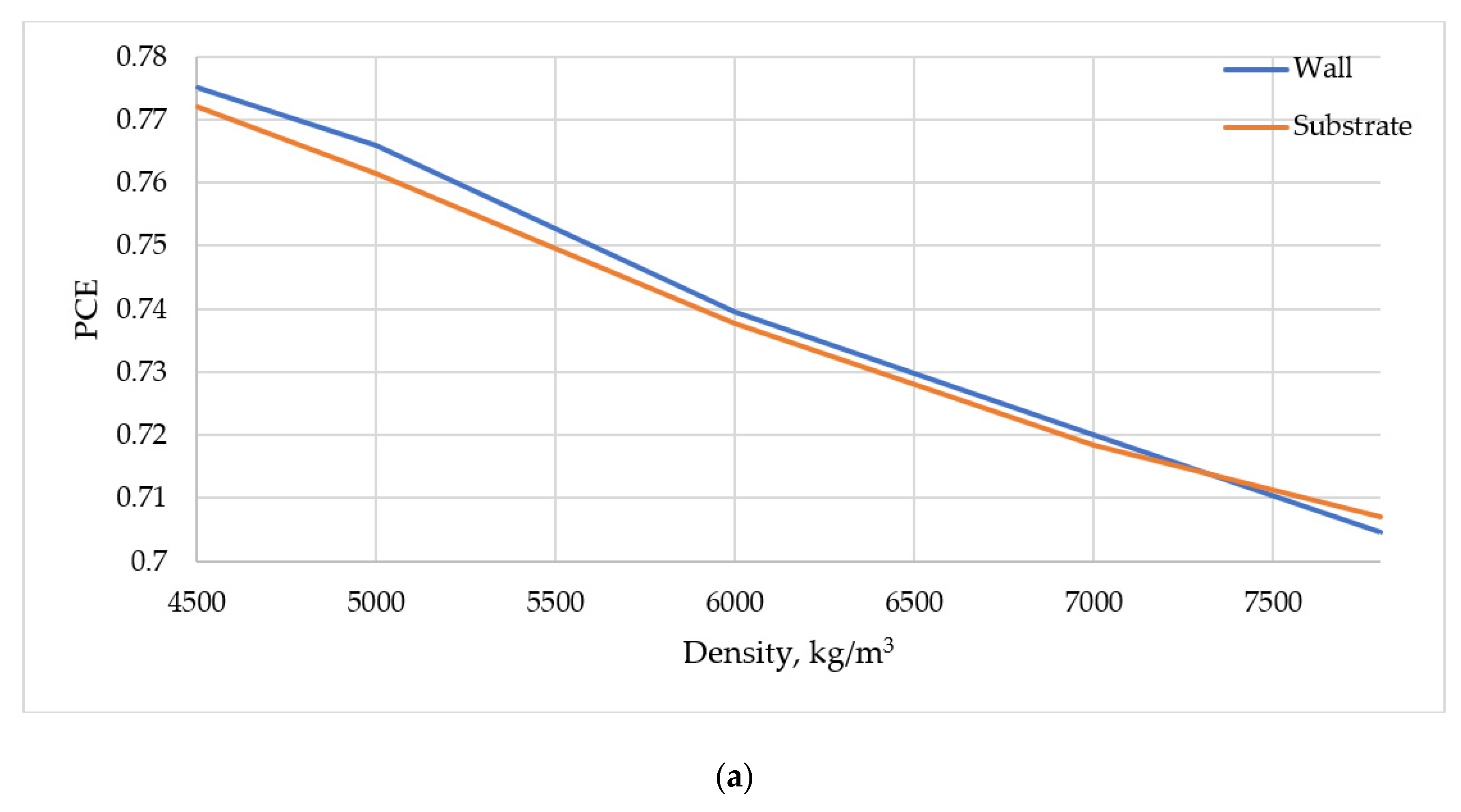
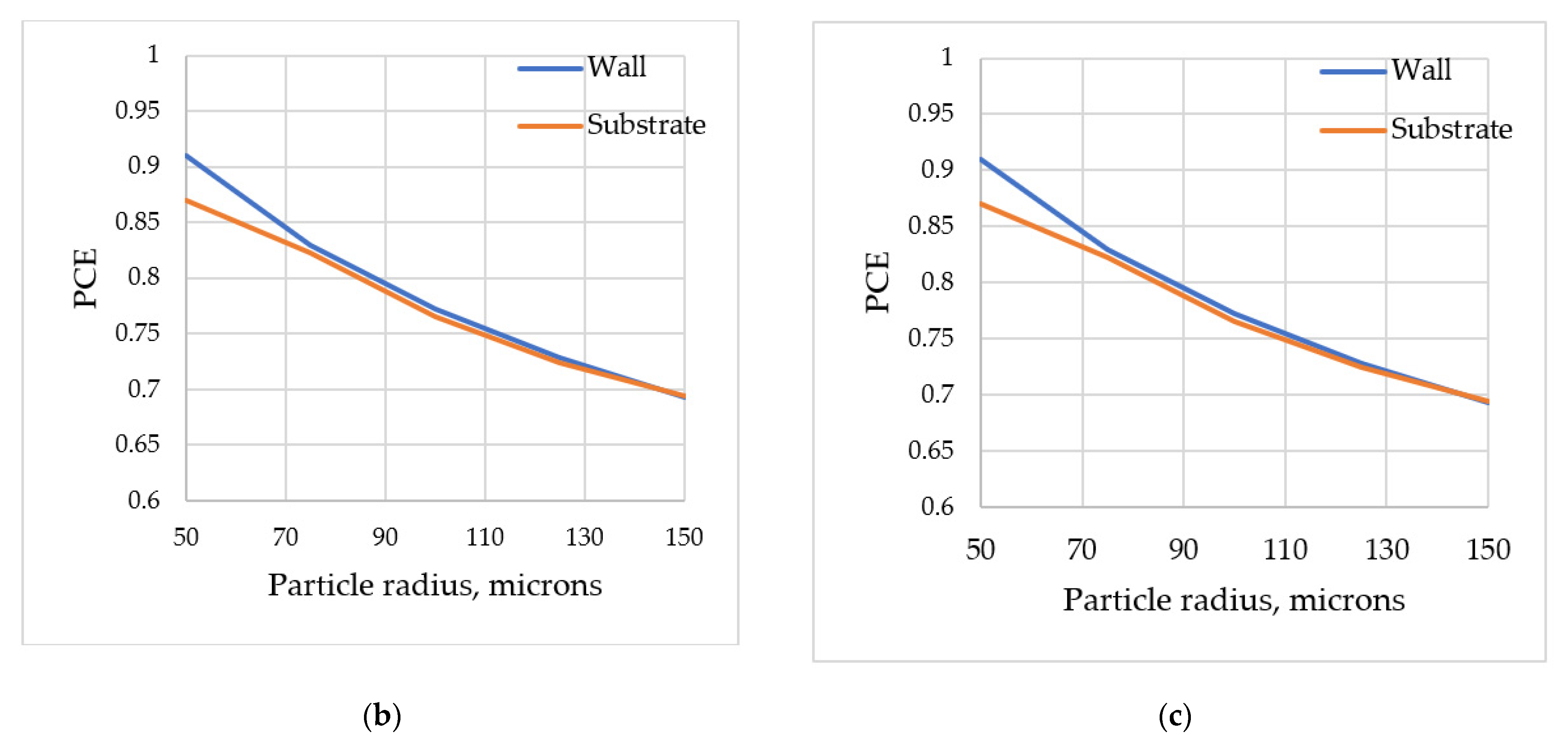
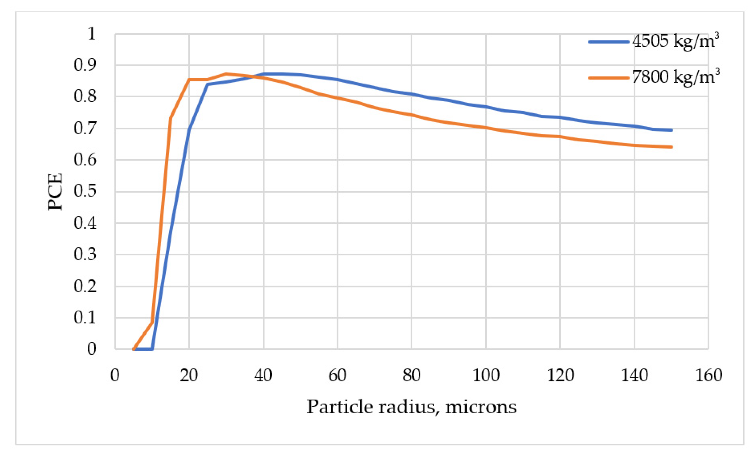
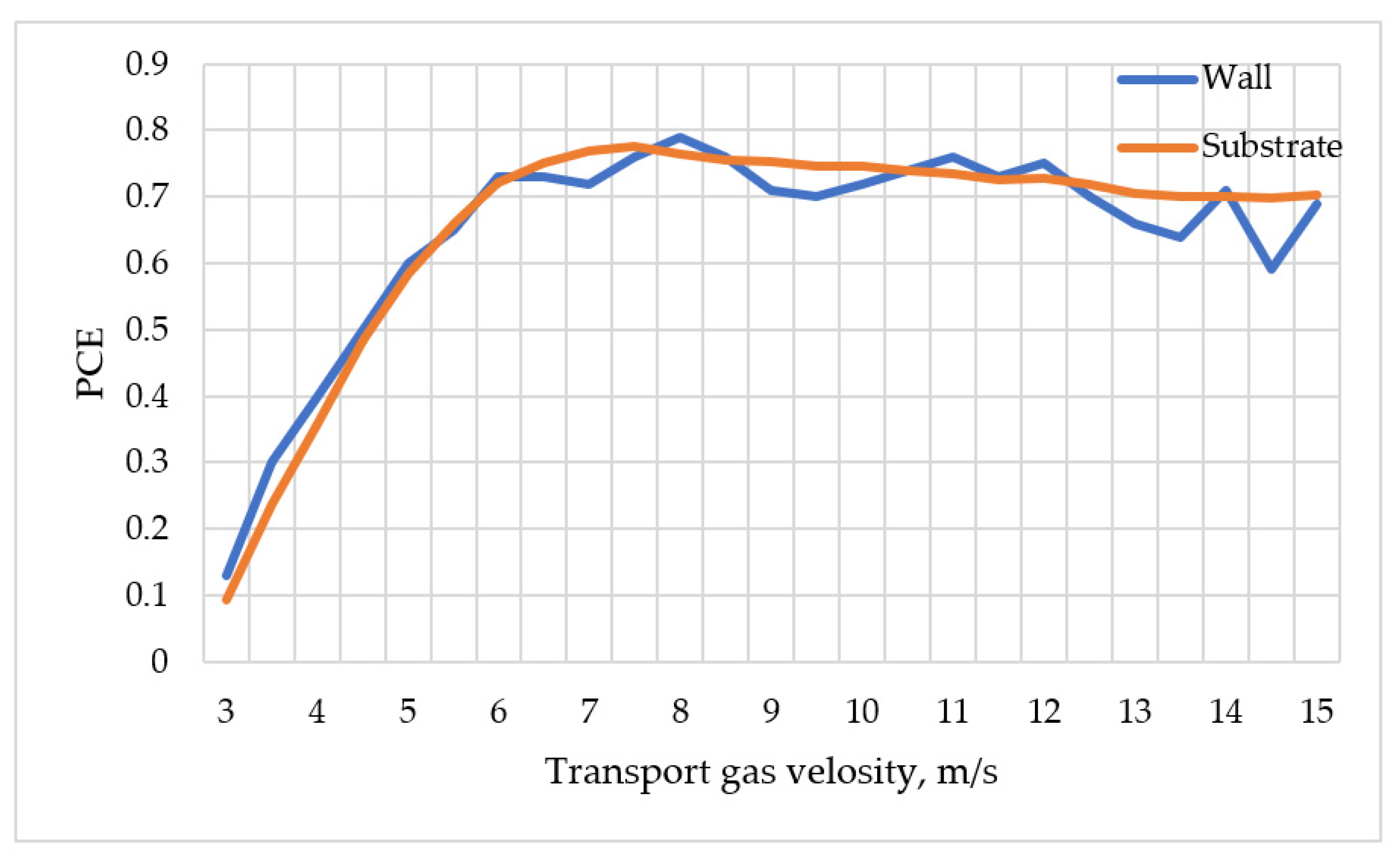
3. Results and Discussion

The simulation was carried out in the COMSOL Multiphysics software package. The areas of interest for the substrate and the wall were 1500 and 2900 mm2, respectively. The mesh consisted of triangular and rectangular elements. The number of nodes for both cases was approximately the same (27,000), as was the number or elements (43,000), and 6000 of them were quads. Grid refinement was carried out in the areas with high gradients of velocity, namely transport nozzle and the substrate surface, which improves the calculation accuracy.
During the calculations, the speed of the transport gas was assumed to be 15 m/s and that of the coaxial gas 5 m/s. Since the internal channels of the nozzle were well polished, the roughness value Ra was assumed to be 0.3 microns. For the substrate, the roughness parameter was 1.6 microns.
The calculation was carried out in two steps. In the first step, the stationary problem of turbulent gas flow was solved, the result of which was the determination of the flow velocity field and gas pressure in the region under consideration. Figure 3 and Figure 4 show the velocity fields for cases with a flat substrate and a wall.
The second step was to calculate the trajectories of powder particles in a given velocity field of the carrier gas found in the first step. The coefficients k n and k τ used to account for the kinetic energy losses of particles in collision with obstacles were set for two cases: collisions with the walls of the nozzle and collisions with obstacles in the form of a substrate or a wall. Since the angle of incidence during the ricochet of particles against the nozzle walls is small, the values of the energy conservation coefficients were assumed to be the same ( k n = k τ ) and equal to 0.9. In the case of a collision with the substrate, the angle of incidence is greater than in the case of a collision with the walls of the nozzle, which means that the energy loss is greater. With this in mind, the energy conservation coefficients were assumed to be equal to 0.5.
Figure 5 and Figure 6 show the trajectories of particle motion for cases with a flat substrate and a wall for powder particles with a normal size distribution with the following parameters: a mean of 100 microns and a standard deviation of 16 microns. At the point of intersection of the axes of the nozzle tubes, the middle of the melt pool with a size of 2 mm is located. Powder particles fall into the melt pool freeze, and the particles that have fallen outside the melt pool will ricochet off the surface of the substrate (Figure 5) or the wall (Figure 6).
When transporting powder particles to the working area, important particle parameters affecting the trajectory are the density of the powder material, which determines the inertia forces, and the size, which affects the magnitude of the impact of viscous forces.
Figure 7 shows the trajectories of particles of different sizes (50 and 150 microns) for a material with a density of 7800 kg/m3. The graphs show that the focusing of the gas–powder jet is better for particles with a size of 50 microns and worsens with increasing size.
Figure 8 shows the dependencies of the powder capture coefficient on (a) the density of the particle material with a constant radius and (b,c) the size for a 2.2 mm melt pool.
As the calculated experiment shows, in the case of a flat substrate, the powder capture coefficient is less than that in the case of a thin wall. This is primarily explained by the geometry of the problem: in the case of a substrate, the structure of the vortex motion of the gas is such that it helps to pull particles away from the “target” (see Figure 3). The size of the powder particles also has a significant effect on the CPR. As can be seen from the graphs in Figure 8b,c, the best focusing is provided by particles with a size of 50 microns, which is consistent with the data presented in Figure 7.
According to studies [28], the trajectory and velocity of small particles, on the order of 5 microns, in a carrier gas jet are mainly determined by the gas velocity field and the viscous forces exert the main influence. Based on the above, it is logical to assume that for a particular powder material, there is such a particle size for which the PCE will be the best. For this purpose, a computational experiment was carried out to determine the PCE for particles of different sizes (5 to 150 microns) in increments of 5 microns for densities of 4505 and 7800 kg/m3. Figure 9 shows a graph of the dependence of the PCE on particle size. As can be seen from the graph, the optimal particle size for a powder material with a density of 4505 kg/m3 is 45 microns and that for a powder material with a density of 7800 kg/m3 is 30 microns.
Figure 10 shows the dependence of PCE on the speed of the transport gas. As can be seen, there is an optimal value of the transport gas velocity (7.5–8 m/s) at which the powder capture efficiency is the best. The data obtained are consistent with the experiments conducted by Gulyaev [19], in which the optimal value of the transport gas was 7.4 m/s for TiC powder with poor sphericity.
The obtained simulation results were qualitatively compared with the results of studies by other authors. For example, the nature of the streamlines and vectors of gas velocities are similar to the results of experimental data obtained in the studies of Dubenskaia [17] and Kovalev [18,19]. The trajectories of the powder particles also qualitatively repeat the results of the distribution in the gas–powder jet obtained in the works [17,18,19] given earlier. After analyzing the results, we can say that the model describes well the physical processes of hydrodynamics and particle tracing. To increase the accuracy of the model, it is necessary to calibrate for a specific powder and technological nozzle with a specific design.

4. Conclusions

This work was aimed at constructing a physical model and a mathematical model of the process of transferring powder particles to the working area during PLV. Powder transport by a carrier gas was considered within the framework of the Euler–Lagrange model: the Navier–Stokes equations averaged by Reynolds together with the k-ε turbulent flow model were used to simulate the dynamics of the carrier gas. To find the trajectory of the powder particles, the equation of motion was used, which includes the viscosity force determined by Stokes’ law, corrected for the case of a moving flow of carrier gas, and the drag coefficient of the particle from the Haider–Levenspiel model. Several empirical parameters determining the inelastic scattering of a powder jet were also introduced.
In the course of the study, velocity fields were obtained when gas flows around the substrate and the wall. Many regularities of the dependence of the powder capture coefficient on the density of powder particles and their size were revealed.
According to the results of the calculated experiment, it is obvious that an obstacle in the form of a substrate or a wall does not greatly affect the PCE and a flat substrate has an even smaller affect. The density of the powder material also affects the PCE for particular particle sizes. For example, for particles of 100 microns, the PCE will be better for a material with a lower density (4505 kg/m3) than for a material with a higher density (7800 kg/m3). The particle size, in the range from 50 to 150 microns, also strongly affects the PCE; and fine particles provide better focusing.
Based on the calculated experiment, the optimal particle sizes of the powder material with a density of 4505 and 7800 kg/m3 were determined, providing the best PCE for a melt bath with a width of 2.2 mm. Their sizes were 45 and 30 microns, respectively.
To adapt the model for different materials of defects, it is proposed to conduct additional experimental studies to clarify the coefficients kgp, kτ, and kn contained in the initial conditions.

Author Contributions

Writing—original draft, S.S.; Writing—review & editing, N.L. and E.V. All authors have read and agreed to the published version of the manuscript.

Funding

This research was funded by the Ministry of Science and Higher Education of the Russian Federation as part of the World-Class Research Center Program: Advanced Digital Technologies (contract no. 075-15-2020-903, dated 16 November 2020).

Institutional Review Board Statement

Not applicable.

Informed Consent Statement

Not applicable.

Data Availability Statement

The data presented in this study are available on request from the corresponding author.

Conflicts of Interest

The authors declare no conflict of interest.

References

  1. Turichin, G.A.; Zemlyakov, E.V.; Klimova, O.G.; Babkin, K.D.; Shamraj, F.A.; Kolodyazhnyj, D.Y. Pryamoe lazernoe vyrashchivanie-perspektivnaya additivnaya tekhnologiya dlya aviadvigatelestroeniya. Svarka i Diagnostika (Weld. Diagn. Russ.) 2015, 3, 54–57. [Google Scholar]
  2. Shedrin, E.Y.U.; Yakushin, N.I.; Popov, A.S.; Turichin, G.A.; Shamraj, F.A.; Kolodyazhnyj, D.Y. Vnedrenie industrial’noj tekhnologii geterofaznoj poroshkovoj lazernoj metallurgii v pao "kuznecov" dlya proizvodstva detalej dvigatelya nk-36st. Additivnye Tekhnol. Nastoyashchee I Budus. (Addit. Technol. Now Future Russ.) 2016, 14. [Google Scholar]
  3. Turichin; Zemlyakov; Babkin; Vil’danov; Golovin; Topalov; Rodionov. 2020 Method for production of topologically optimized water-jet propellers impeller by direct laser growth method. RU Patent 2718823 C1, 14 April 2020. [Google Scholar]
  4. Turichin, G.A.; Zemlyakov, E.V.; Klimova-Korsmik, O.G.; Babkin, K.D. Pryamoe lazernoe vyrashchivanie krupnogabar-itnyh metallicheskih komponentov morskoj i aviacionnoj tekhniki. In Proceedings of the Vysokoenergeticheskie i Special’nye Materialy: Demilitarizaciya, Antiterrorizm i Grazhdanskoe Primenenie (Collection of Conference HEMS-2018 Reports In Russian), Tomsk, Russia, 3–5 September 2018. [Google Scholar]
  5. Magerramova; Babkin; Klimova-Korsmik; Turichin. Method of manufacturing hollow disk of gas turbine engine. RU Patent 2672989 C1, 22 November 2018. [Google Scholar]
  6. Turichin, G.A.; Kotov, V.S.; Barskov, V.V.; Reznikova, R.K. Additivnye tekhnologii v kachestve osnovy vnedreniya op-erativnogo remonta energeticheskogo oborudovaniya korablei i sudov VMF. Transp. Delo Ross. (Transp. Bus. Russ. Russ.) 2021, 1, 144–147. [Google Scholar]
  7. Turichin, G.A.; Korsmik, R.S.; Klimova-Korsmik, O.G.; Zemlyakov, E.V.; Babkin, K.D. Lazernaya poroshkovaya voss-tanovitel’naya naplavka lopatok gazoturbinnogo dvigatelya. In Proceedings of the Problemy i Perspektivy Razvitiya Dvigatelestroeniya (Problems and Prospects of Engine Building Development in Russian), Samara, Russia, 22–24 June 2016. [Google Scholar]
  8. Gol’dfarb, V.I.; Trubachev, E.S.; Haranzhevskij, E.V.; Ipatov, A.G.; Bogdanov, K.V.; Matveeva, Y.U. Novaya tekhnologiya lazernoj modifikacii poverhnostej nizkoskorostnyh tyazhelonagruzhennyh opor skol’zheniya. Vestn. IzhGTU Im. MT Kalashnikova (J. Kalashnikov ISTU Russ.) 2017, 20, 112–117. [Google Scholar]
  9. Chen, B.; Mazumder, J. Role of process parameters during additive manufacturing by direct metal deposition of Inconel 718. Rapid Prototyp. J. 2017, 23, 919–929. [Google Scholar] [CrossRef]
  10. Izadi, M.; Farzaneh, A.; Mohammed, M.; Gibson, I.; Rolfe, B. A review of laser engineered net shaping (LENS) build and process parameters of metallic parts. Rapid Prototyp. J. 2020, 26, 1059–1078. [Google Scholar] [CrossRef]
  11. Turichin, G.; Zemlyakov, E.; Klimova, O.; Babkin, K. Hydrodynamic Instability in High-speed Direct Laser Deposition for Additive Manufacturing. Phys. Procedia 2016, 83, 674–683. [Google Scholar] [CrossRef] [Green Version]
  12. Liu, H.; He, X.; Yu, G.; Wang, Z.; Li, S.; Zheng, C.; Ning, W. Numerical simulation of powder transport behavior in laser cladding with coaxial powder feeding. Sci. China Ser. G Physics. Mech. Astron. 2015, 58, 104701. [Google Scholar] [CrossRef] [Green Version]
  13. Zekovic, S.; Rajeev, D.; Radovan, K. Numerical simulation and experimental investigation of gas–powder flow from radially symmetrical nozzles in laser-based direct metal deposition. Int. J. Mach. Tools Manuf. 2007, 47, 112–123. [Google Scholar] [CrossRef]
  14. Li, L.; Huang, Y. Numerical and experimental study on powder stream characteristics in coaxial laser cladding process. In Proceedings of the 6th International Conference on Welding Science and Engineering, Beijing, China, 13–15 October 2015. [Google Scholar]
  15. Liu, Z.; Zhang, H.C.; Peng, S.; Kim, H.; Du, D.; Cong, W. Analytical modeling and experimental validation of powder stream distribution during direct energy deposition. Addit. Manuf. 2019, 30, 100848. [Google Scholar] [CrossRef]
  16. Varaksin, A.Y. Turbulent Particle-Laden Gas Flows; Springer: Berlin, Germany, 2007. [Google Scholar]
  17. Volkov, K.; Emel’yanov, V. Techeniya gaza s Chasticami [Gas Flows with Particles]; FIZMATLIT: Moscow, Russia, 2008. (In Russian) [Google Scholar]
  18. Boothroyd, R.G. Flowing Gas Solids Suspensions; Chapman and Hall: London, UK, 1971. [Google Scholar]
  19. Gulyaev, I.P.; Kovalev, O.B.; Pinaev, P.A.; Grachev, G.N. Optical diagnostics of radiation interaction with the powder stream laterally transported during laser cladding. Opt. Lasers Eng. 2019, 126, 105877. [Google Scholar] [CrossRef]
  20. Doubenskaia, M.; Kulish, A.; Sova, A.; Petrovskiy, P.; Smurov, I. Experimental and numerical study of gas-powder flux in coaxial laser cladding nozzles of Precitec. Surf. Coatings Technol. 2020, 406, 126672. [Google Scholar] [CrossRef]
  21. Kovalev, O.B.; Zaitsev, A.V.; Novichenko, D.; Smurov, I. Theoretical and Experimental Investigation of Gas Flows, Powder Transport and Heating in Coaxial Laser Direct Metal Deposition (DMD) Process. J. Therm. Spray Technol. 2010, 20, 465–478. [Google Scholar] [CrossRef]
  22. Kovalev, O.B.; Bedenko, D.V.; Zaitsev, A.V. Development and application of laser cladding modeling technique: From coaxial powder feeding to surface deposition and bead formation. Appl. Math. Model. 2018, 57, 339–359. [Google Scholar] [CrossRef]
  23. Kovalev, O.B.; Kovaleva, I.O.; Smurov, I.Y. Numerical investigation of gas-disperse jet flows created by coaxial nozzles during the laser direct material deposition. J. Mater. Process. Technol. 2017, 249, 118–127. [Google Scholar] [CrossRef]
  24. Kuzmin, D.; Mierka, O.; Turek, S. On the implementation of the κ-ε turbulence model in incompressible flow solvers based on a finite element discretisation. Int. J. Comput. Sci. Math. 2007, 1, 193–206. [Google Scholar] [CrossRef]
  25. Wendt, J.F. (Ed.) Omputational Fluid Dynamics: An Introduction; Springer: Berlin/Heidelberg, Germany, 2008. [Google Scholar]
  26. Jones, W.P.; Launder, B.E. The prediction of laminarization with a two-equation model of turbulence. Int. J. Heat Mass Transf. 1972, 15, 301–314. [Google Scholar] [CrossRef]
  27. Haider, A.; Levenspiel, O. Drag coefficient and terminal velocity of spherical and nonspherical particles. Powder Technol. 1989, 58, 63–70. [Google Scholar] [CrossRef]
  28. Gladush, G.G.; Smurov, I. Physics of Laser Materials Processing: Theory and Experiment; Springer: Berlin, Germany, 2011. [Google Scholar]
Figure 1. Diagrams of the studied PLV geometries: (a) for a flat substrate and (b) for a thin wall.
Metals 11 02002 g001
Figure 2. Scheme of reflection of a powder particle from the wall.
Metals 11 02002 g002
Figure 3. The substrate: the field of gas flow velocities; the black lines indicate the streamlines.
Metals 11 02002 g003
Figure 4. The wall: the field of gas flow velocities; the black lines indicate the streamlines.
Metals 11 02002 g004
Figure 5. Trajectories of movement of powder particles for the case of a flat substrate.
Metals 11 02002 g005
Figure 6. Particle motion trajectories for the wall case.
Metals 11 02002 g006
Figure 7. Trajectories of powder particles for different particle sizes: (a) 50 microns and (b) 150 microns.
Metals 11 02002 g007
Figure 8. Graphs of the dependence of the powder capture efficiency on (a) particle density, (b) the particle size for a density of 4505 kg/m3, and (c) the particle size for a density of 7800 kg/m3.
Metals 11 02002 g008aMetals 11 02002 g008b
Figure 9. Graph of the dependence of the PCE on the particle size.
Metals 11 02002 g009
Figure 10. Graph of the dependence between transport gas velocity and powder capture efficiency.
Metals 11 02002 g010
Publisher’s Note: MDPI stays neutral with regard to jurisdictional claims in published maps and institutional affiliations.

