
Study on Performance of PVD AlTiN Coatings and AlTiN-Based Composite Coatings in Dry End Milling of Hardened Steel SKD11

Abstract
:1. Introduction
2. Materials and Methods
2.1. Testing Materials
2.2. Milling Tests
3. Results and Discussion
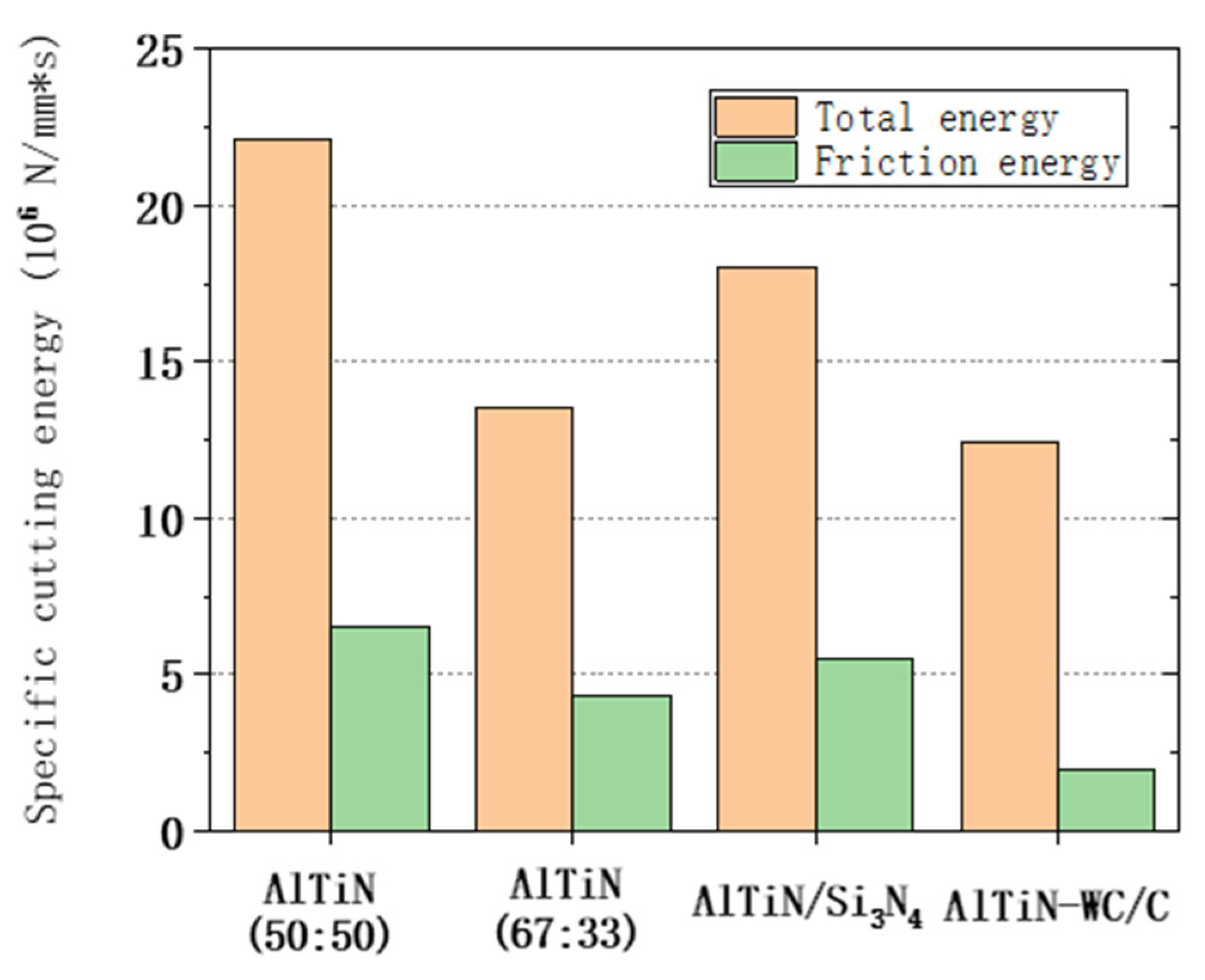
3.1. The Force Components and Specific Energy
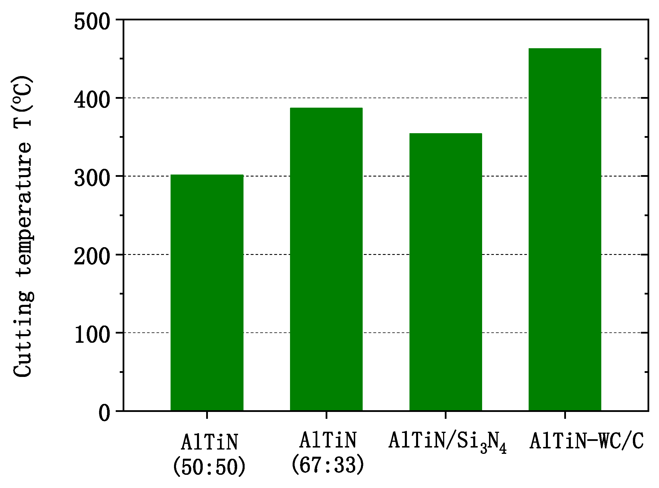
3.2. Milling Temperature
3.3. Tool Wear
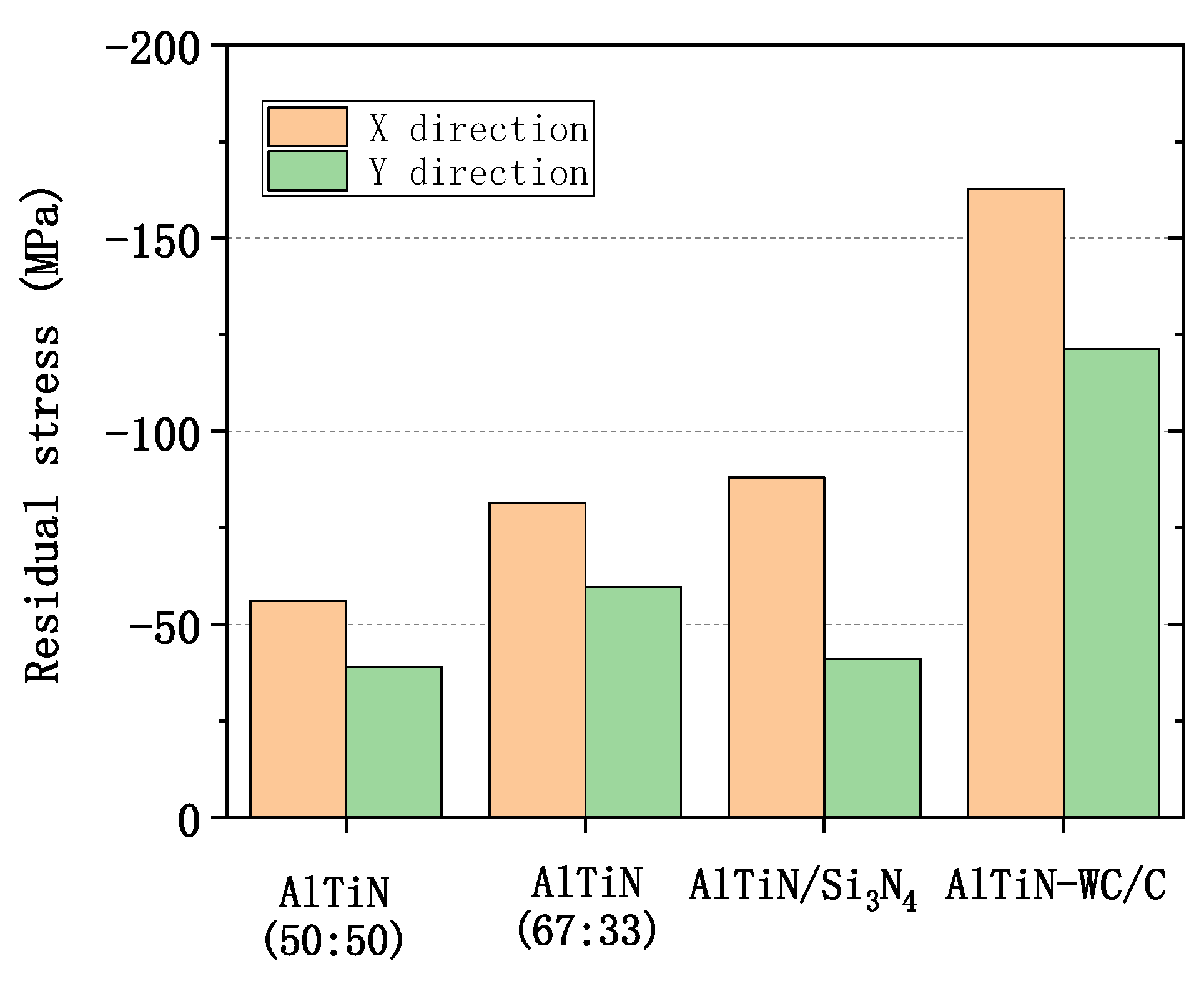
3.4. Surface Integrity
4. Conclusions
Author Contributions
Funding
Institutional Review Board Statement
Informed Consent Statement
Conflicts of Interest
References
- Wang, C.; Ding, F.; Tang, D.; Zheng, L.; Li, S.; Xie, Y. Modeling and simulation of the high-speed milling of hardened steel SKD11 (62 HRC) based on SHPB technology. Int. J. Mach. Tools Manuf. 2016, 108, 13–26. [Google Scholar] [CrossRef]
- Gong, F.; Zhao, J.; Jiang, Y.; Tao, H.; Li, Z.; Zang, J. Fatigue failure of coated carbide tool and its influence on cutting performance in face milling SKD11 hardened steel. Int. J. Refract. Met. Hard Mater. 2017, 64, 27–34. [Google Scholar] [CrossRef]
- Gong, F.; Zhao, J.; Ni, X.; Liu, C.; Sun, J.; Zhang, Q. Wear and breakage of coated carbide tool in milling of H13 steel and SKD11 hardened steel. SN Appl. Sci. 2019, 1, 1111. [Google Scholar] [CrossRef] [Green Version]
- Pimenov, D.Y.; Abbas, A.T.; Gupta, M.K.; Erdakov, I.N.; Soliman, M.S.; El Rayes, M.M. Investigations of surface quality and energy consumption associated with costs and material removal rate during face milling of AISI 1045 steel. Int. J. Adv. Manuf. Technol. 2020, 107, 3511–3525. [Google Scholar] [CrossRef]
- Salur, E.; Kuntoğlu, M.; Aslan, A.; Pimenov, D.Y. The effects of MQL and dry environments on tool wear, cutting temperature, and power consumption during end milling of AISI 1040 steel. Metals 2021, 11, 1674. [Google Scholar] [CrossRef]
- Lawal, S.; Choudhury, I.; Nukman, Y. Application of vegetable oil-based metalworking fluids in machining ferrous metals—A review. Int. J. Mach. Tools Manuf. 2012, 52, 1–12. [Google Scholar] [CrossRef]
- An, Q.; Cai, C.; Zou, F.; Liang, X.; Chen, M. Tool wear and machined surface characteristics in side milling Ti6Al4V under dry and supercritical CO2 with MQL conditions. Tribol. Int. 2020, 151, 106511. [Google Scholar] [CrossRef]
- Javaroni, R.L.; Lopes, J.C.; Diniz, A.E.; Garcia, M.V.; Ribeiro, F.S.F.; Tavares, A.B.; Talon, A.G.; Sanchez, L.E.D.A.; de Mello, H.J.; Aguiar, P.R.; et al. Improvement in the grinding process using the MQL technique with cooled wheel cleaning jet. Tribol. Int. 2020, 152, 106512. [Google Scholar] [CrossRef]
- Gajrani, K.K.; Suvin, P.S.; Kailas, S.V.; Rajurkar, K.P.; Sankar, M.R. Machining of hard materials using textured tool with minimum quantity nano-green cutting fluid. CIRP J. Manuf. Sci. Technol. 2021, 35, 410–421. [Google Scholar] [CrossRef]
- Sankaranarayanan, R.; Rajesh Jesudoss Hynes, N.; Senthil Kumar, J.; Krolczyk, G.M. A comprehensive review on research developments of vegetable-oil based cutting fluids for sustainable machining challenges. J. Manuf. Process. 2021, 67, 286–313. [Google Scholar] [CrossRef]
- Ramirez, C.; Ismail, A.I.; Gendarme, C.; Dehmas, M.; Aeby-Gautier, E.; Poulachon, G.; Rossi, F. Understanding the diffusion wear mechanisms of WC-10%Co carbide tools during dry machining of titanium alloys. Wear 2017, 390–391, 61–70. [Google Scholar] [CrossRef] [Green Version]
- Krolczyk, G.; Maruda, R.; Krolczyk, J.; Wojciechowski, S.; Mia, M.; Nieslony, P.; Budzik, G. Ecological trends in machining as a key factor in sustainable production—A review. J. Clean. Prod. 2019, 218, 601–615. [Google Scholar] [CrossRef]
- Klocke, F.; Eisenblätter, G. Dry cutting. CIRP Ann. 1997, 46, 519–526. [Google Scholar] [CrossRef]
- Yuan, J.; Fox-Rabinovich, G.S.; Veldhuis, S.C. Control of tribofilm formation in dry machining of hardened AISI D2 steel by tuning the cutting speed. Wear 2018, 402–403, 30–37. [Google Scholar] [CrossRef]
- Thakur, A.; Gangopadhyay, S. Dry machining of nickel-based super alloy as a sustainable alternative using TiN/TiAlN coated tool. J. Clean. Prod. 2016, 129, 256–268. [Google Scholar] [CrossRef]
- Kumar, A.; Bauri, R.; Naskar, A.; Chattopadhyay, A. Characterization of HiPIMS and DCMS deposited TiAlN coatings and machining performance evaluation in high speed dry machining of low and high carbon steel. Surf. Coat. Technol. 2021, 417, 127180. [Google Scholar] [CrossRef]
- Fujii, Y.; Imai, T.; Miyamoto, Y.; Ueda, N.; Hosoo, M.; Harigai, T.; Suda, Y.; Takikawa, H.; Tanoue, H.; Kamiya, M.; et al. Dry machining of metal using an engraving cutter coated with a droplet-free ta-C film prepared via a T-shape filtered arc deposition. Surf. Coat. Technol. 2016, 307, 1029–1033. [Google Scholar] [CrossRef]
- Cavaleiro, D.; Figueiredo, D.; Moura, C.W.; Cavaleiro, A.; Carvalho, S.; Fernandes, F. Machining performance of TiSiN(Ag) coated tools during dry turning of TiAl6V4 aerospace alloy. Ceram. Int. 2021, 47, 11799–11806. [Google Scholar] [CrossRef]
- Arndt, M.; Kacsich, T. Performance of new AlTiN coatings in dry and high speed cutting. Surf. Coat. Technol. 2003, 163–164, 674–680. [Google Scholar] [CrossRef]
- PalDey, S.; Deevi, S.C. Single layer and multilayer wear resistant coatings of (Ti,Al)N: A review. Mater. Sci. Eng. A 2003, 342, 58–79. [Google Scholar] [CrossRef]
- He, Q.; DePaiva, J.M.; Kohlscheen, J.; Beake, B.D.; Veldhuis, S.C. Study of wear performance and tribological characterization of AlTiN PVD coatings with different Al/Ti ratios during ultra-high speed turning of stainless steel 304. Int. J. Refract. Met. Hard Mater. 2021, 96, 105488. [Google Scholar] [CrossRef]
- Lian, Y.; Long, Y.; Zhao, G.; Mu, C.; Li, X.; Deng, J.; Xie, C. Performance of CrCN-WS2 hard/soft composite coated tools in dry cutting of titanium alloys. J. Manuf. Process. 2020, 54, 201–209. [Google Scholar] [CrossRef]
- Kumar, C.S.; Majumder, H.; Khan, A.; Patel, S.K. Applicability of DLC and WC/C low friction coatings on Al2O3/TiCN mixed ceramic cutting tools for dry machining of hardened 52100 steel. Ceram. Int. 2020, 46, 11889–11897. [Google Scholar] [CrossRef]
- Benedetti, M.; Fontanari, V.; Torresani, E.; Girardi, C.; Giordanino, L. Investigation of lubricated rolling sliding behaviour of WC/C, WC/C-CrN, DLC based coatings and plasma nitriding of steel for possible use in worm gearing. Wear 2017, 378–379, 106–113. [Google Scholar] [CrossRef]
- Vera, E.; Vite, M.; Lewis, R.; Gallardo, E.; Laguna-Camacho, J. A study of the wear performance of TiN, CrN and WC/C coatings on different steel substrates. Wear 2011, 271, 2116–2124. [Google Scholar] [CrossRef]
- Liu, Z.; An, Q.; Xu, J.; Chen, M.; Han, S. Wear performance of (nc-AlTiN)/(a-Si3N4) coating and (nc-AlCrN)/(a-Si3N4) coating in high-speed machining of titanium alloys under dry and minimum quantity lubrication (MQL) conditions. Wear 2013, 305, 249–259. [Google Scholar] [CrossRef]
- Zhang, S.; Wu, W.; Chen, W.; Yang, S. Structural optimisation and synthesis of multilayers and nanocomposite AlCrTiSiN coatings for excellent machinability. Surf. Coat. Technol. 2015, 277, 23–29. [Google Scholar] [CrossRef]
- Uhlmann, E.; Fuentes, J.O.; Gerstenberger, R.; Frank, H. nc-AlTiN/a-Si3N4 and nc-AlCrN/a-Si3N4 nanocomposite coatings as protection layer for PCBN tools in hard machining. Surf. Coat. Technol. 2013, 237, 142–148. [Google Scholar] [CrossRef]
- Shaw, M.C.; Cookson, J. Metal Cutting Principles; Oxford University Press: New York, NY, USA, 2005. [Google Scholar]
- Altintas, Y. Manufacturing Automation-Metal Cutting Mechanics, Machine Tool Vibrations and CNC Design, 2nd ed.; Cambridge University Press: New York, NY, USA, 2012. [Google Scholar]


| Properties | Density | Young’s Modulus | Poisson’s Ratio | Hardness | ||||
| 8400 kg/m3 | 208 GPa | 0.3 | 60–62 HRC | |||||
| Compositions wt.% | C | Si | Mn | Cr | Mo | V | P< | S< |
| 1.40~1.60 | 0.40 | 0.60 | 11.00~13.00 | 0.80~1.20 | 0.20~0.50 | 0.03 | 0.03 | |
| Properties | Hardness | Bending Strength | Compressive Strength | Grain Size |
| 1600 HV30 | 4300 N/mm2 | 6250 N/mm2 | 0.8 μm | |
| Compositions wt.% | W | C | Co | Cr |
| 80.99 | 9.78 | 8.83 | 0.4 |
| Geometric Parameters | Cutting Parameters | ||
|---|---|---|---|
| Diameter | 12 mm | Cutting speed | 75 m/min |
| Cutter fluted | 4 | Feed rate | 0.1 mm/tooth |
| Rake angle | 10° | Axial depth | 6 mm |
| Clearance angle | 5° | Radial depth | 0.3 mm |
| Helix angle | 45° | Cooling fluid | Dry |
| Cutting Length | AlTiN (50:50) | AlTiN (67:33) | AlTiN/Si3N4 | AlTiN-WC/C |
|---|---|---|---|---|
| 0.8 m |  |  |  |  |
| 1.6 m | 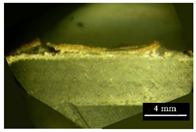 | 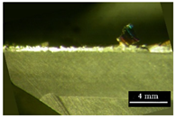 | 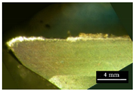 |  |
| 2.4 m |  | 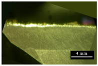 |  |  |
| 3.2 m |  |  |  |  |
| P1 | Element | Wt% | At% | P2 | Element | Wt% | At% |
|---|---|---|---|---|---|---|---|
| CK | 09.56 | 35.21 | NK | 06.35 | 13.50 | ||
| CrK | 11.60 | 09.87 | OK | 13.64 | 25.38 | ||
| FeK | 65.13 | 51.61 | AlK | 24.41 | 26.93 | ||
| WL | 13.72 | 03.30 | SiK | 02.10 | 02.23 | ||
| TiK | 38.72 | 24.07 | |||||
| MnK | 01.87 | 01.01 | |||||
| FeK | 12.91 | 06.88 |
Publisher’s Note: MDPI stays neutral with regard to jurisdictional claims in published maps and institutional affiliations. |
© 2021 by the authors. Licensee MDPI, Basel, Switzerland. This article is an open access article distributed under the terms and conditions of the Creative Commons Attribution (CC BY) license (https://creativecommons.org/licenses/by/4.0/).
Share and Cite
Jing, L.; Chen, M.; An, Q. Study on Performance of PVD AlTiN Coatings and AlTiN-Based Composite Coatings in Dry End Milling of Hardened Steel SKD11. Metals 2021, 11, 2019. https://doi.org/10.3390/met11122019
Jing L, Chen M, An Q. Study on Performance of PVD AlTiN Coatings and AlTiN-Based Composite Coatings in Dry End Milling of Hardened Steel SKD11. Metals. 2021; 11(12):2019. https://doi.org/10.3390/met11122019
Chicago/Turabian StyleJing, Lulu, Ming Chen, and Qinglong An. 2021. "Study on Performance of PVD AlTiN Coatings and AlTiN-Based Composite Coatings in Dry End Milling of Hardened Steel SKD11" Metals 11, no. 12: 2019. https://doi.org/10.3390/met11122019