Article

Verification of Possibility of Molten Steels Decopperization with ZnAl2O4

1
Institute of Iron and Steel Technology, TU Bergakademie, 09599 Freiberg, Germany
2
Institute of Ceramics, Refractories and Composite Materials, TU Bergakademie, 09599 Freiberg, Germany
*
Author to whom correspondence should be addressed.
Metals 2021, 11(12), 2030; https://doi.org/10.3390/met11122030 (registering DOI)
Submission received: 24 November 2021 / Revised: 8 December 2021 / Accepted: 10 December 2021 / Published: 14 December 2021

Abstract

:
In the previous research works, ZnAl2O4 material was considered as one of the solutions for the decopperization process of molten steels; up to 33% of decopperization efficiency was reported by utilising the ZnAl2O4 filter. In order to verify the decopperization possibility of ZnAl2O4 materials, iron-based alloys with various copper and carbon contents were interacted with ZnAl2O4 substrates in a heating microscope under an argon gas atmosphere at 1600 °C. Fe-Cu alloys were found to react with the ZnAl2O4 substrate during the interaction process, and a reaction layer with a complex composition around the alloy droplet was formed; however, Cu was not detected in the reaction layer. Cu was later found infiltrated inside of the ZnAl2O4 substrates. Furthermore, the Cu-Zn compounds were detected when the copper content in Fe-Cu alloys was 10 wt% Cu. After interaction experiments, copper was decreased in all cases. Thereby, the copper evaporation and infiltration into the ZnAl2O4 substrate were considered as the reasons for copper loss. Moreover, oxygen dissolved in melt was found to have a great effect on the copper evaporation process.

1. Introduction

After centuries of industry development, steel scrap’s stock has become a very prospective raw material resource for steel reproduction. Steel scrap is a cheap but abundant raw material with a high energy content. Every ton of recycled steel scrap saves 1134 kg of iron ore, 635 kg of coal, and 54 kg of lime [1]. However, this new material supplier requires more advanced recycling technology and treatment due to the residual elements contained in the steel scraps.
Copper, as a common tramp element in steel scrap, strongly prevents the effective use of steel scrap, i.e., during the heat treatment process, liquid copper forms and penetrates the grain boundaries, causing cracking [2,3]. As reported in the literature [2], the hot shortness is exhibited when the copper concentration is greater than 0.2 wt%. Copper dissolved in steel melts could not be oxidized in the presence of iron due to its lower affinity for oxygen than iron. Through a common pyrometallurgical method, copper could not be removed from molten steel. In order to apply steel scrap, dilution with virgin pig iron or direct reduced iron (DRI) became the industry solution.
Daehn et al. [4] reported the huge negative influence of copper in constraining future global steel recycling. A variety of methods during the last decades for the removal of copper from steel scrap were suggested based on the unique properties of copper, including that copper has a good affinity to sulfur, a high evaporation rate at high temperatures, and forms volatile gas species with Cl. Thereafter, a series of decopperization methods were reported: (1) treatment by reaction with sulfur-containing slag [5,6,7,8]; (2) vacuum distillation [2,9,10,11,12]; (3) treatment by reaction with chlorine-containing slag [13]; (4) filtration [2]. More decopperization methods and investigations have been reported and summarized in reviews by Sandig et al. [14] and Daehn et al. [15]. Besides the above-mentioned methods, a reactive filtration method was reported in earlier literature [16,17,18]. Wieliczko et al. [16] filtrated copper-containing liquid alloy by applying an Al- and Zn-based ceramic spinel (ZnAl2O4); 30–33% copper was removed. Moreover, a 70% of decopperization rate was achieved by blowing fine-grain ZnAl2O4 spinel powder into the steel under laboratory conditions. Li et al. [17] stated that intermetallic Cu-Zn compound would be formed by adding Al2O3-ZnO-C materials in liquid Fe-Cu alloy. Namely, the carbon could reduce ZnO (as shown in Equation (1)), then the released Zn would react with Cu and forming Cu-Zn compound. Later, the formed intermetallic Cu-Zn compound would deposit on the surface of Al2O3. Through this process, copper could be successfully removed from the liquid Fe-Cu alloys. The proposed mechanism is illustrated in Figure 1. However, these researchers did not present the in-detail morphology of the Cu-Zn compound formation on Al2O3 ceramic with corresponded chemical analysis. Furthermore, the formation of intermetallic compound Cu-Zn was also stated during the welding process between Zn-coated steel and Cu electrodes by Kim et al. [19].
ZnO + C = Zn + CO
The unclarified copper-filtration possibility of ZnAl2O4 filter and the urgency of finding an efficient decopperization method led the present work aim to verify the possibility of ZnAl2O4 as a prospective solution for decopperization. Therefore, in the present work, various contents of copper-/carbon-bearing iron were interacted with ZnAl2O4 substrate. For the comparison, pure alumina was also interacted with alloy samples.

2. Materials and Methods

2.1. ZnAl2O4 Substrates’ Preparation

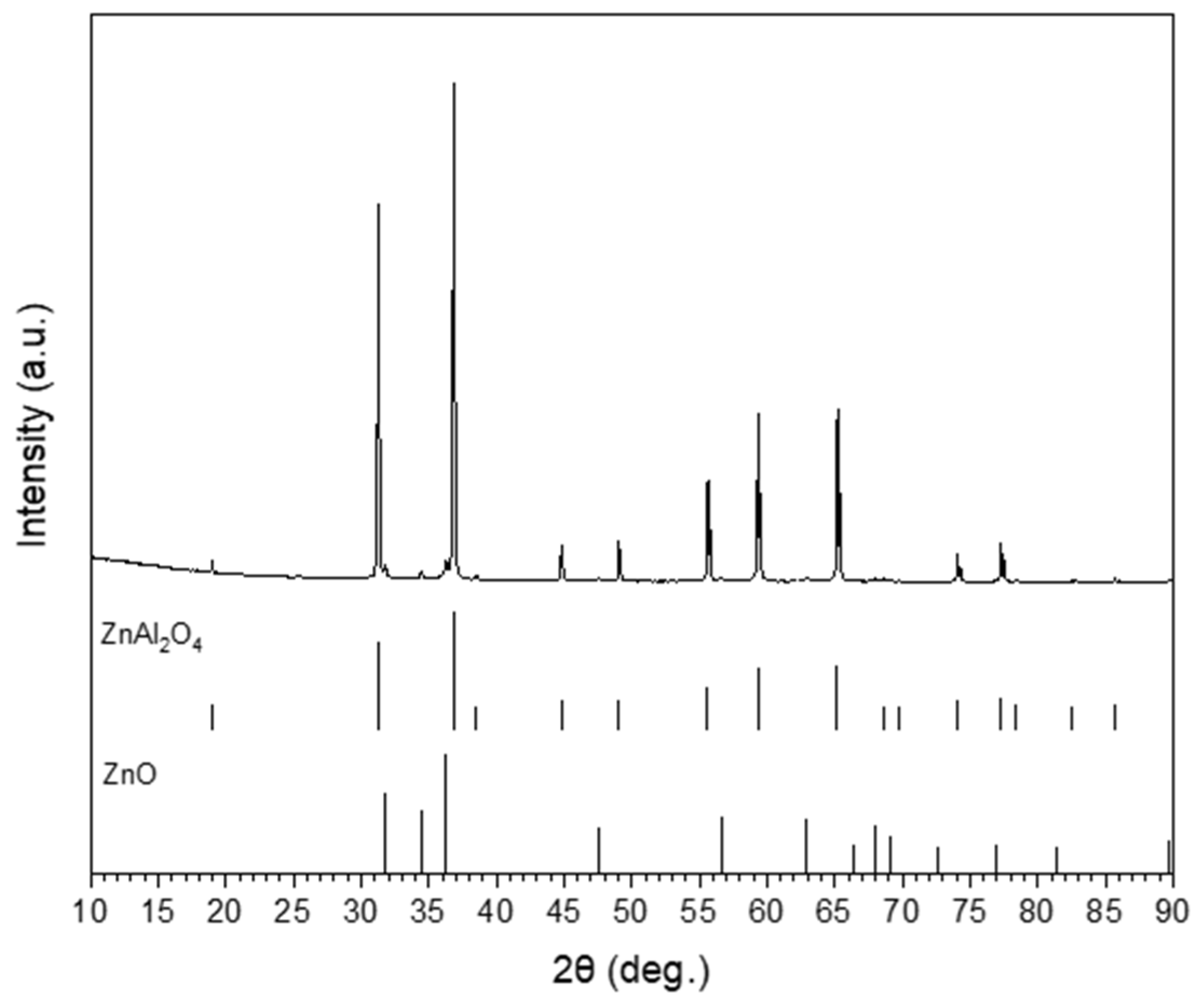
To prepare the used ZnAl2O4-substrates, pure ZnO (90/RS Carl Jäger, Hilgert, Germany) and Al2O3 (Martoxid®MR70, Martinswerk, Bergheim, Germany) were used. The raw materials were mixed in a molar ratio of 48 mol% Al2O3 and 52 mol% ZnO. A water-based slurry containing the oxides as well as 0.4 wt% Dispex®A40 (CIBA, Basel, Switzerland) as a wetting agent and 0.2 wt% Optapix®AC170 (Zschimmer&Schwarz, Lahnstein, Germany) as a pressing agent were mixed with 25 wt% distilled water (related to dry mass of oxides) in a PET container with alumina balls. The container was rotated for 12 h to homogenize the slurry. After that, the mixture was dried at 110 °C to less than 3% water. The dried raw material was crushed and sieved to less than <1 mm maximum grain size. The prepared granules were now 120 MPa uniaxial pressed to substrates with a diameter of 50 mm and a thickness of 5 mm and sintered in an electric-heated furnace under an oxidizing atmosphere at 1600 °C with a heating rate of 2 K/min and a dwell time of 5 h. After the sintering step, the substrates were grinded and polished on one side to ensure a flat surface for the wetting experiments. XRD (in Figure 2) investigations show the conversion of 96.6 wt% ZnAl2O4 and 3.4 wt% ZnO reaction product.

2.2. Fe-Cu Alloys’ Preparation and Experimental Setup

A cold crucible induction melter KIT (CCIM KIT) (LINN High Therm GmbH, Eschenfelden, Germany) was applied to produce Fe-Cu alloys. The in-detailed description about CCIM is reported elsewhere [20]. Armco iron with the composition as shown in Table 1, pure copper (99.999%), and graphite were used as primary materials for the sample preparation. The prepared Fe-Cu alloys are listed in Table 2. The Fe-Cu alloy samples were prepared into a cylindrical form with a height of 8 mm and diameter of 7.5 mm, then etched with HCl and H2O (HCl/H2O = 1:1) mixed solution.
The experimental interaction was conducted in a heating microscope under argon with a flow rate of 0.3 L/min (2–3 ppm oxygen) at 1600 °C. Both the heating and cooling rate were kept at 40 K/min. The interaction process was monitored by a CCD camera (IMAGINGSOURCE GmbH, Bremen, Germany). A simplified schematic illustration of the experimental setup is shown in Figure 3. An in-detail description was presented in the previous publication [21]. The conducted experiments are summarized in Table 2.
The general chemical composition of iron alloys was analyzed by the spark spectrometer Foundry-Master UV (Oxford Instruments, Abingdon, England). Moreover, Bruker G4 Ikarus and Bruker G8 Galileo combustion analyzers were applied to estimate the O, C, and S contents. After the interaction experiments, metal droplet and ZnAl2O4 substrates were embedded into epoxy resin and perpendicularly cut for cross-sectional analysis. Scanning electron microscopy (SEM) in combination with energy-dispersive X-ray spectroscopy (EDX) was used for morphology and chemical determination (Ultra55, Zeiss NTS GmbH, Heidelberg, Germany).

3. Results and Discussion

3.1. Experimental Observation

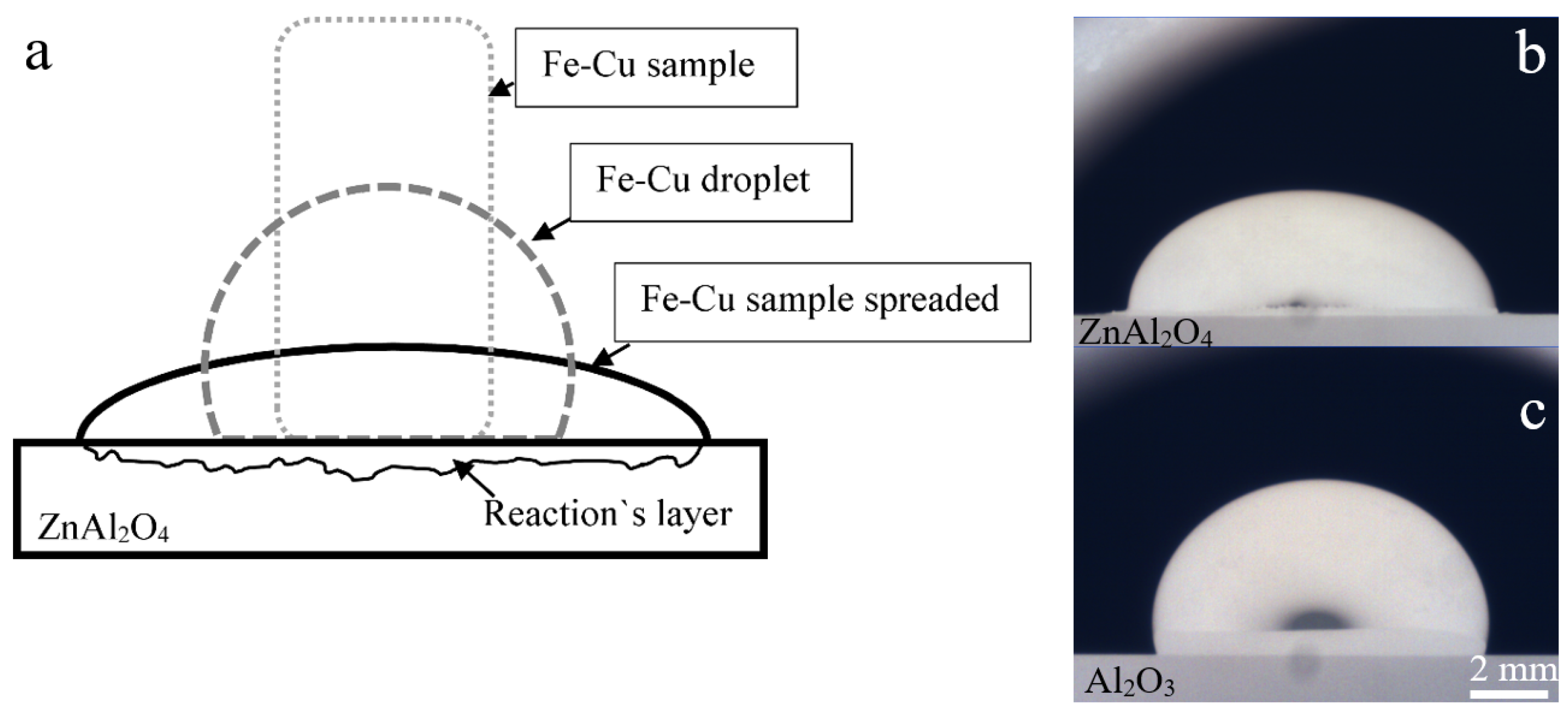
A melting mechanism of Fe-Cu alloys on ZnAl2O4 substrate is illustrated in Figure 4a. As shown in Figure 4a, Fe-Cu alloys start to melt when the temperature is high enough (melting temperature of iron 1538 °C). Later, a symmetrical liquid droplet is formed. With a longer interaction period, the Fe-Cu alloys liquid spread on the ZnAl2O4 substrate. Moreover, during all the interaction experiments, the formation of gas bubbles inside the molten Fe-Cu alloys was observed; with the addition of 0.5 wt% C, the gas formation was much heavier than 40 ppm C.
Figure 4b indicates an image of liquid Fe-Cu (1 wt% Cu) alloys spread on the ZnAl2O4 substrate. Furthermore, after interaction with the ZnAl2O4 substrate, a reactive layer and plenty of powder were found in the experimental chamber; according to the chemical analysis, this powder consisted of ZnO. It indicates that the ZnO in the ZnAl2O4 substrate was reduced by the carbon contained in the Fe-Cu alloys, then re-oxidized by the oxygen contained in the protective gas. On the other hand, a perfect symmetrical Fe-Cu alloy liquid droplet was presented on the Al2O3 substrate, as shown in Figure 4c. No reaction was observed.

3.2. Interfacial and Cross Sectional Analysis

Figure 5a shows an image of Fe-1% Cu alloy interacted with ZnAl2O4 substrate; a reaction layer was formed around iron sample. According to the SEM/EDX analysis, the reaction layer consists of complex elements including O, Al, Fe, Zn, Mn, and Si without Cu. (see Figure 5b,d)). Elements such as Si, Mn, and Fe are transferred from the side of the iron sample. At the cross section (see Figure 5c), only some Fe was detected.
Figure 6a indicates the cross section between Fe-1% Cu-0.5% C alloy and ZnAl2O4 substrate. The cross section was divided into four different subareas; the copper content was EDX measured at each subarea; the measured copper content is depicted in Figure 6c. The copper content decreases from the ZnAl2O4 substrate interface (Figure 6a, subarea 4) to inside of the substrate. Figure 6b indicates the Fe-Cu alloy interaction area, according to the measured point 1 and 2 (Figure 6b), the detected ratio of Cu and Fe in ZnAl2O4 substrate is similar to with Fe-1% Cu alloy. It indicates that Cu was infiltrated into the ZnAl2O4 substrate along with liquid Fe-Cu alloy; the formation of intermetallic compound Cu and Zn was not detected.
After the interaction between iron alloy with 10 wt% Cu and ZnAl2O4 substrate, metallic Cu was detected on the bottom of the newly formed reactive layer as shown in Figure 7a. Figure 7b is the cross-section area between alloy and substrate, it shows that the compounds with bright colour were scattered in this area. EDX analysis revealed that point 3 (86.84 wt% Cu) is pure copper, which is transferred from the Fe-10% Cu sample side. Furthermore, point 4 consists mostly of Al and Fe. Finally, the element’s ratio (Cu/Zn = 0.6) at point 5 indicates that it is a Cu5Zn8 compound.
Fe-Cu alloy is known as an alloy with a metastable miscibility gap. During the solidification process, if a single-phase liquid is undercooled into the metastable miscibility gap, it will divide into two liquids, iron and copper [22]. According to Brillo and Egry [23], the energy of mixing ∆G is strongly positive for Fe-Cu. Consequently, Fe-Cu does not form a homogeneous solution at all temperatures and compositions. Since copper has a greater density than iron [24], it could accumulate at the bottom of the alloys.

3.3. The Composition of Fe-Cu Alloys

The measured chemical compositions of Fe-Cu alloys after the interaction are listed in Table 3. The copper content was found to be decreased in all cases. For the Al2O3 substrate cases, the copper losses at various cases were close to each other; the copper loss was considered as mainly contributing to the copper evaporation. Moreover, the oxygen content was slightly decreased for Al2O3 substrate cases. In the heating microscope, a graphite tube is installed for the heating process; it could react with the oxygen contained in the protective gas forming CO gas. Hence, the formed carbon monoxide (CO) in the experimental atmosphere might decrease a fraction of oxygen in the liquid samples. Furthermore, when liquid Fe-Cu alloy interacts with ZnAl2O4 substrates, more copper was found vanished with the addition of 0.5% carbon. For ZnAl2O4 substrates, copper evaporation into the atmosphere and transfer into the ZnAl2O4 substrates were the reasons for the copper loss. Thereby, with an addition of carbon content (0.5 wt% C) in the Fe-Cu alloys, more ZnO was reduced into Zn and O; it increased the porosity of the ZnAl2O4 substrates. Furthermore, due to the positive mixing energy ∆G for molten Fe-Cu and high density of copper [23], more copper would accumulate at the liquid sample’s bottom. Therefore, more copper would have infiltrated into the ZnAl2O4 substrates along with liquid Fe-Cu samples.
In the meantime, the reduction of ZnO in ZnAl2O4 substrates supplied the oxygen into Fe-Cu alloys; consequently, the oxygen content after interaction with ZnAl2O4 substrates was increased. Besides this, aluminium was found to slightly dissolve into the iron sample and after interaction with Al2O3 and ZnAl2O4 substrates. According to the previous literature [21,25], under present low-oxygen partial pressure and high temperature, Al2O3 would dissolve into the liquid iron. The carbon content was strongly decreased after interacting with ZnAl2O4 substrates. However, the carbon content after making contact with the Al2O3 substrates kept the same.

3.4. Copper Evaporation Mechanism

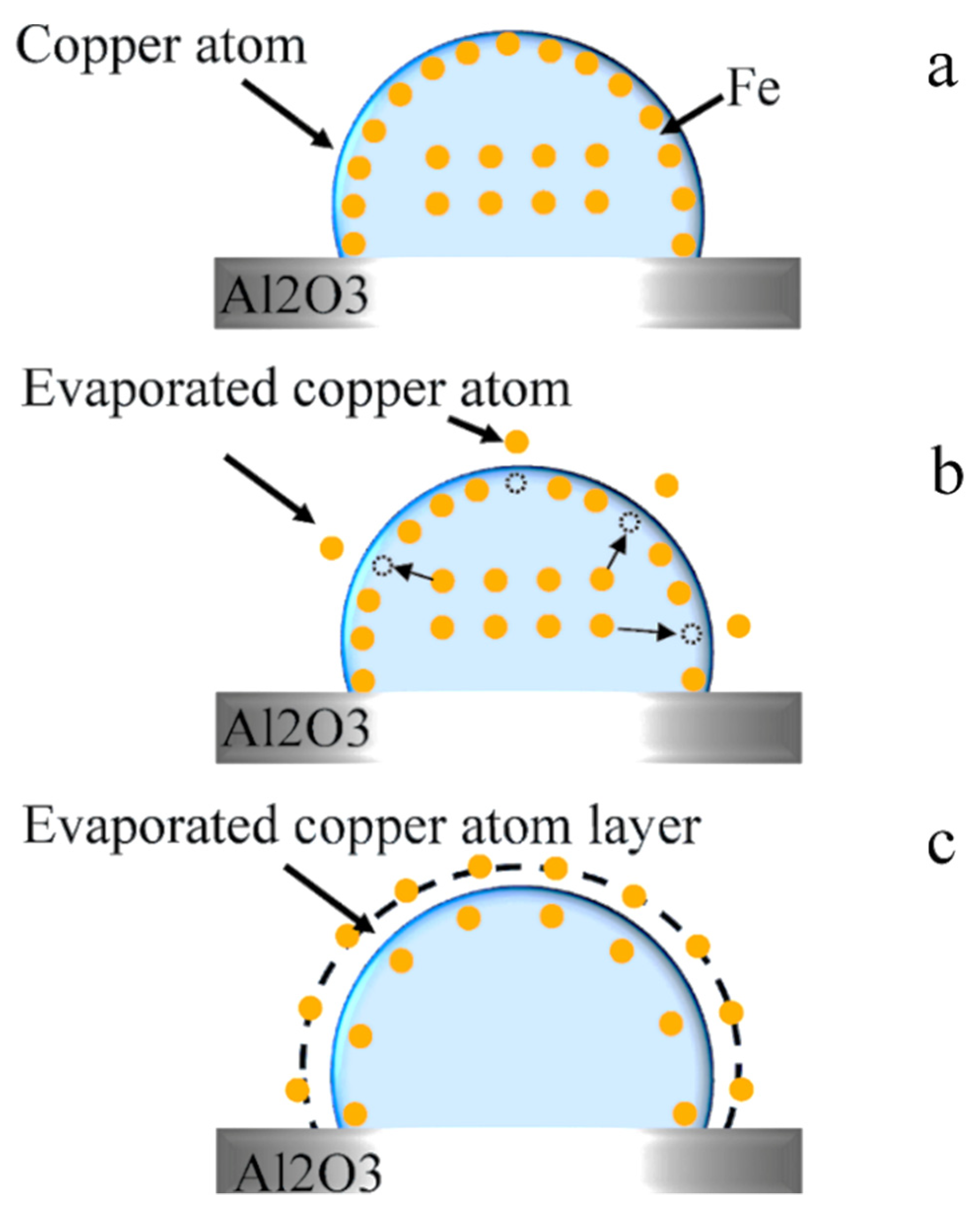
In the present investigation, copper was mainly decreased due to its high evaporation rate. According to the literature related to the copper evaporation [10,26,27,28,29], the copper evaporation process from liquid iron can be divided into three main stages: (1) copper transfer from the bulk of the liquid phase to the interface; (2) copper evaporation from the liquid metal surface; (3) transfer of the copper vapours from the interface to the core of the gaseous phase, as illustrated in Figure 8.
Fischer et al. [30] stated that the apparent evaporation rate constant k C u can be expressed by Equation (2). As shown in Equation (2), k C u L is liquid phase mass transfer coefficient (m·s−1), k C u e is the free evaporation rate constant of Cu (m·s−1), and k C u G is the gas phase mass transfer coefficient (m·s−1).
k C u = 1 1 k C u L + 1 k C u e + 1 k C u G  

3.5. Effect of Oxygen on Copper Evaporation

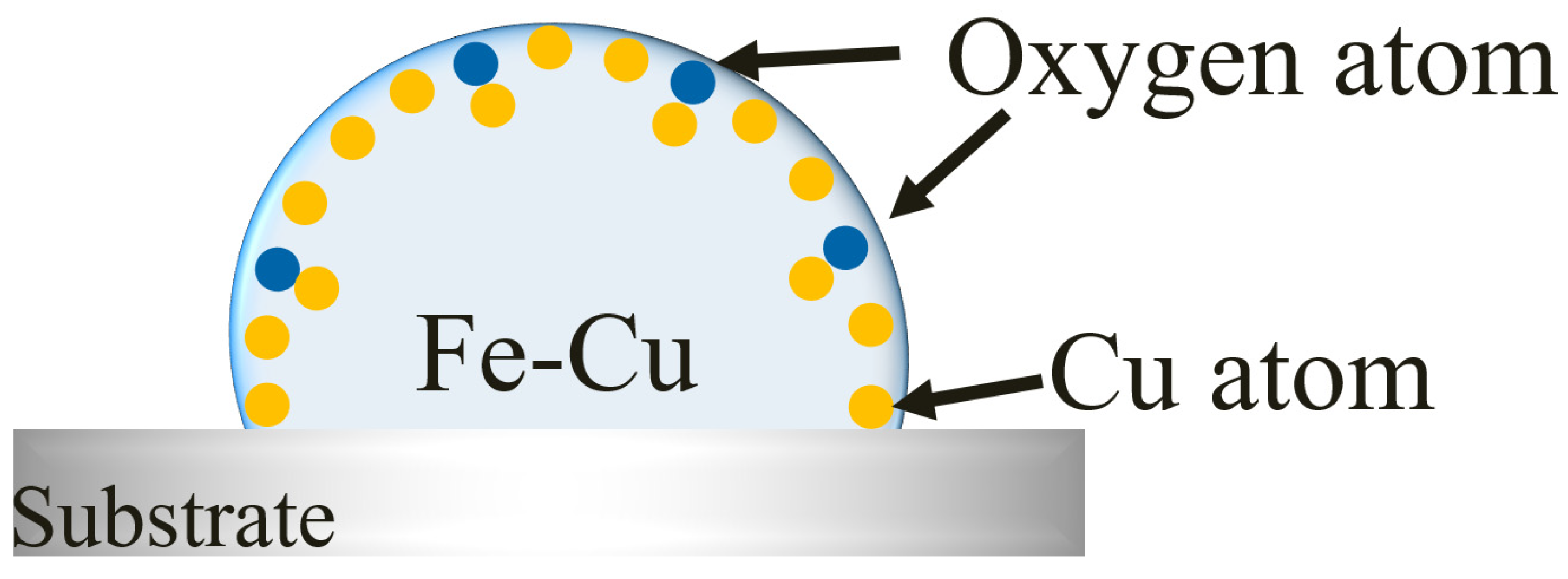
Oxygen is known as a surface-active element; it accumulates on the liquid Fe-Cu alloy surface and blocks the available sites for metal–gas reactions. Consequently, oxygen prevented the copper evaporation to atmosphere, as illustrated in Figure 9. Furthermore, a few ppm of oxygen can significantly reduce the surface tension value [31]. Thereby, its effect on the free evaporation rate constant of copper from liquid iron can be expressed by assuming Langmuir’s ideal adsorption isotherm [32,33].
k C u e = k C u e o ( 1 θ O )  
where k C u e is the free evaporation rate constant of Cu on the surface of liquid iron (m·s−1), k C u e o is the free evaporation rate constant of Cu on the surface of oxygen free liquid iron (m·s−1) and θ O is the degree of surface coverage by absorbed oxygen.
K O C u · a O = θ O ( 1 θ O )  
where K O C u is the adsorption equilibrium constant of oxygen on the surface of liquid iron and a O is the activity of oxygen in liquid iron.
k C u e = k C u e o ( 1 + K O C u · a O )  
The value of K O C u was reported as 110 in the Equation (6) by Lee [34].
Υ F e O = 1.890 0.299 I n ( 1 + 110   a O )  
Therefore, high oxygen content greatly prevented the copper evaporation in the Fe-Cu alloys. Carbon addition would decrease the oxygen content in the melts and enhance the copper evaporation.
Moreover, oxygen reduces the activity coefficient of copper γ c u (as shown in (7)) in the liquid iron, due to the negative interaction coefficient between copper and oxygen, e C u o = 0.05   at 1600 °C [35].
l o g   γ c u = i e c u i [ m a s s %   i ] = e c u i · [ m a s s %   i ] + e c u O · [ m a s s %   O ]  
where i is the elements in the Fe-Cu alloy and e c u i is interaction coefficient of Cu in the liquid iron.

4. Conclusions

Both ZnAl2O4 and Al2O3 substrates have interacted with liquid Fe-Cu alloys containing carbon to verify the decopperization possibility of ZnAl2O4 materials. After experiments, copper was found to decrease with both ZnAl2O4 and Al2O3 substrates. The copper evaporation and its infiltration along with liquid Fe-Cu alloys into the ZnAl2O4 substrate were the explanations for the copper loss. For the Fe-Cu (0.5–1.0 wt% Cu) alloys, no metallic Cu and Zn compounds were detected with ZnAl2O4 substrates. The intermetallic compound Cu5Zn8 was only detected with Fe-Cu (10 wt% Cu) alloy. According to the obtained experimental results, it can be concluded that the decopperization of liquid steels with ZnAl2O4 filter is implausible.
Besides this, the oxygen contents after interacting with ZnAl2O4 substrates were strongly increased with the decompose of ZnO. The oxygen dissolved into the liquid Fe-Cu alloys noticeably affected the copper evaporation, which led to a lower copper loss. Based on the experimental results, ZnAl2O4 materials showed a higher decopperization efficiency when the Fe-Cu alloys contained more carbon. However, this result was caused by the infiltration of Fe-Cu alloys into the ZnAl2O4 substrate with enhanced porosity.

Author Contributions

X.W., D.C. and O.V. designed and conducted the experiments; S.D. prepared Al2O3 and ZnAl2O4 substrates; X.W., writing—original draft preparation; C.G.A. and O.V. reviewed the paper. All authors have read and agreed to the published version of the manuscript.

Funding

The investigation was founded by the DFG (German Research Foundation), Project-ID: 169148856-SFB 920, subproject C01 at the Technical University Bergakademie Freiberg.

Institutional Review Board Statement

Not applicable.

Informed Consent Statement

Not applicable.

Data Availability Statement

Not applicable.

Acknowledgments

The authors are grateful for the financial support and helpful discussion from SFB 920 project.

Conflicts of Interest

The authors declare no conflict of interest.

References

  1. Rod, O.; Becker, C.; Nylén, M. Opportunities and Dangers of Using Residual Elements in Steels: A Literature Survey; Jernknotoret Report: Stockholm, Sweden, 2006. [Google Scholar]
  2. Savov, L.; Volkova, E. Copper and tin in steel scrap recycling. Mat. Geoenviron. 2003, 50, 627–640. [Google Scholar]
  3. Zhao, G.-H.; Zhang, J.; Li, J.; Li, H.-Y.; Liu, H.-T.; Ma, L.-F. Effect of copper on edge cracking behavior and microstructure of rolled austenitic stainless steel plate. J. Iron Steel Res. Int. 2021, 1–14. [Google Scholar] [CrossRef]
  4. Daehn, K.E.; Serrenho, A.C.; Allwood, J.M. How Will Copper Contamination Constrain Future Global Steel Recycling? Environ. Sci. Technol. 2017, 51, 6599–6606. [Google Scholar] [CrossRef] [PubMed]
  5. Wang, J.-J.; Guo, S.-X.; Zhou, L.; Li, Q. Slag for decopperization and sulphur control in molten steel. J. Iron Steel Res. Int. 2009, 16, 17–21. [Google Scholar] [CrossRef]
  6. Cohen, A.; Blander, M. Removal of copper from carbon-saturated iron with an aluminum sulfide/ferrous sulfide flux. Met. Mater. Trans. A 1998, 29, 493–495. [Google Scholar] [CrossRef]
  7. Shimpo, R.; Ogawa, O.; Fukaya, Y.; Ishikawa, T. Copper removal from carbon-saturated molten iron with Al2S3-FeS flux. Met. Mater. Trans. A 1997, 28, 1029–1037. [Google Scholar] [CrossRef]
  8. Uchida, Y.-I.; Matsui, A.; Kishimoto, Y.; Miki, Y. Fundamental Investigation on Removal of Copper from Molten Iron with Na2CO3–FeS Fluxes. ISIJ Int. 2015, 55, 1549–1557. [Google Scholar] [CrossRef] [Green Version]
  9. Savov, L.; Janke, D. Evaporation of Cu and Sn from Induction-stirred Iron-based Melts Treated at Reduced Pressure. ISIJ Int. 2000, 40, 95–104. [Google Scholar] [CrossRef] [Green Version]
  10. Zaitsev, A.I.; Zaitseva, N.E.; Shakhpazov, E.K.; Mogutnov, B.M. Evaporation of Copper from Iron Melts. ISIJ Int. 2004, 44, 639–646. [Google Scholar] [CrossRef] [Green Version]
  11. Taguchi, K.; Ono-Nakazato, H.; Usui, T. Enhancement of Evaporation Removal Rate of Copper in Molten Iron by the Silicon and/or Carbon Addition. Resour. Process. 2004, 51, 158–162. [Google Scholar] [CrossRef] [Green Version]
  12. Savov, L.; Tu, S.; Janke, D. Methods of Increasing the Rate of Tin Evaporation from Iron-based Melts. ISIJ Int. 2000, 40, 654–663. [Google Scholar] [CrossRef] [Green Version]
  13. Hu, X.; Yan, Z.; Jiang, P.; Zhu, L.; Chou, K.; Matsuura, H.; Tsukihashi, F. Removal of Copper from Molten Steel using FeO–SiO2–CaCl2 Flux. ISIJ Int. 2013, 53, 920–922. [Google Scholar] [CrossRef] [Green Version]
  14. Sandig, E.F.; Chebykin, D.; Prutchykova, V.V.; Fabrychnaya, O.; Volkova, O. Review: Possibilities of Steel Scrap Decopperization. Mater. Sci. Forum 2019, 959, 145–160. [Google Scholar] [CrossRef]
  15. Daehn, K.E.; Serrenho, A.C.; Allwood, J. Finding the Most Efficient Way to Remove Residual Copper from Steel Scrap. Met. Mater. Trans. A 2019, 50, 1225–1240. [Google Scholar] [CrossRef]
  16. Wieliczko, A.G.; Griszczenko, J.N.; Krucinski, M. Technological efficiency of liquid steel decopperizing. Hut. Wiad. Hut. 1998, 65, 256–259. (In Polish) [Google Scholar]
  17. Li, L.; Xiang, C.; Zhao, P.; Wang, C.; Tian, H.; Li, S. Decopperization in Steel Melt through Filtration. J. Iron Steel Res. Int. 1998, 10, 5–7. (In Chinese) [Google Scholar]
  18. Li, S.; Yu, B.; Li, S.; Li, L. Exploration on Decoppering of Molten Steel by Filtering. Engineering Chem. Metallurgy 2000, 21, 314–317. (In Chinese) [Google Scholar]
  19. Kim, Y.G.; Kim, I.J.; Kim, J.S.; Chung, Y.I.; Choi, D.Y. Evaluation of Surface Crack in Resistance Spot Welds of Zn-Coated Steel. Mater. Trans. 2014, 55, 171. [Google Scholar] [CrossRef] [Green Version]
  20. Shyrokykh, T.; Wei, X.; Seetharaman, S.; Volkova, O. Vaporization of Vanadium Pentoxide from CaO-SiO2-VOx Slags During Alumina Dissolution. Met. Mater. Trans. A 2021, 52, 1472–1483. [Google Scholar] [CrossRef]
  21. Wei, X.; Yehorov, A.; Storti, E.; Dudczig, S.; Fabrichnaya, O.; Aneziris, C.G.; Volkova, O. Phenomenon of Whiskers Formation in Al2O3-C-Refractories. Adv. Eng. Mater. 2021, 2100718. [Google Scholar] [CrossRef]
  22. He, J.; Zhao, J.Z.; Ratke, L. Solidification microstructure and dynamics of metastable phase transformation in undercooled liquid Cu–Fe alloys. Acta Mater. 2006, 54, 1749–1757. [Google Scholar] [CrossRef]
  23. Brillo, J.; Egry, I. Surface tension of nickel, copper, iron and their binary alloys. J. Mater. Sci. 2005, 40, 2213–2216. [Google Scholar] [CrossRef]
  24. Korobeinikov, I.I.; Chebykin, D.; Yu, X.; Seetharaman, S.; Volkova, O. Density of tin, silver and copper. Arch. Mater. Sci. Eng. 2018, 92, 28–32. [Google Scholar] [CrossRef]
  25. Zienert, T.; Dudczig, S.; Fabrichnaya, O.; Aneziris, C.G. Interface reactions between liquid iron and alumina–carbon refractory filter materials. Ceram. Int. 2015, 41, 2089–2098. [Google Scholar] [CrossRef]
  26. Labaj, J. Kinetics of Coper Evaporation from the Fe-Cu Alloys Under Reduced Pressure. Arch. Met. Mater. 2012, 57, 165–172. [Google Scholar] [CrossRef] [Green Version]
  27. Ono-Nakazato, H.; Taguchi, K.; Usui, T. Estimation of the Evaporation Rate of Copper and Tin from Molten Iron-Silicon Alloy. ISIJ Int. 2003, 43, 1105–1107. [Google Scholar] [CrossRef] [Green Version]
  28. Ohno, R. Kinetics of Evaporation of Manganese, Copper and Sulfur from Iron Alloys in Vacuum Induction Melting. Trans. Iron Steel Inst. Jpn. 1977, 17, 732–741. [Google Scholar] [CrossRef] [Green Version]
  29. Łabaj, J.; Oleksiak, B.; Siwiec, G. Study of copper removal from liquid iron. Metalurgija 2011, 50, 265–268. [Google Scholar]
  30. Fischer, W.A.; Janke, D.; Stahlschmidt, K. Vergleich experimenteller Ergebnisse und theoretischer Ansätze zur Verdampfung von Begleitelementen aus Stahlschmelzen. Arch. Eisenhuttenwes. 1974, 45, 509–515. [Google Scholar] [CrossRef]
  31. Morohoshi, K.; Uchikoshi, M.; Isshiki, M.; Fukuyama, H. Surface Tension of Liquid Iron as Functions of Oxygen Activity and Temperature. ISIJ Int. 2011, 51, 1580–1586. [Google Scholar] [CrossRef] [Green Version]
  32. Yoshida, T.; Nagasaka, T.; Hino, M. Effect of Oxygen on the Evaporation Rate of Lead from Liquid Copper under Reduced Pressure. ISIJ Int. 2001, 41, 706–715. [Google Scholar] [CrossRef] [Green Version]
  33. Hayakawa, S.; Choh, T.; Inouye, M. Effect of Dissolved Oxygen on the Rates of Evaporation of Molten Iron and Copper. Trans. Iron Steel Inst. Jpn. 1982, 22, 637–645. [Google Scholar] [CrossRef] [Green Version]
  34. Lee, J.; Morita, K. Evaluation of Surface Tension and Adsorption for Liquid Fe-S Alloys. ISIJ Int. 2002, 42, 588–594. [Google Scholar] [CrossRef] [Green Version]
  35. Schenck, H.; Steinmetz, E. Wirkungsparameter von Begleitelement Eisenlegierungen und Ihre Gegenseitigen Beziehungen; Verlag Stahleisen: Essen, Germany, 1968. [Google Scholar]
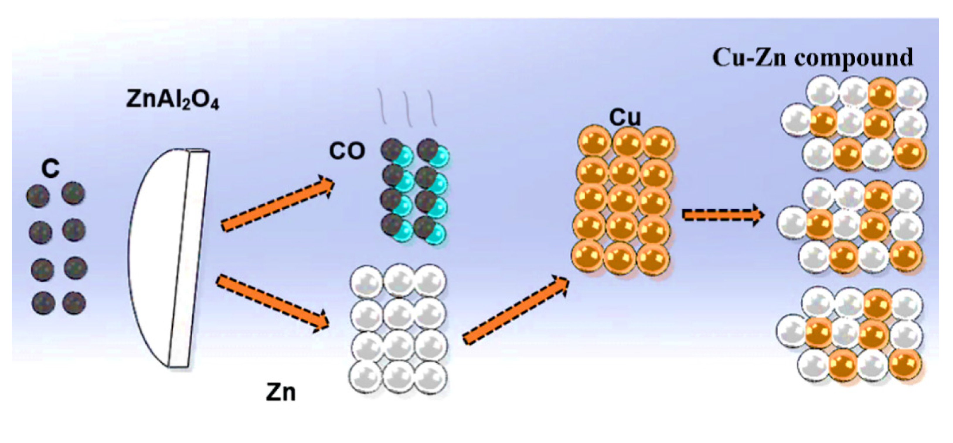
Figure 1. The schematic illustration of proposed filtration mechanism by ZnAl2O4 as filter materials.
Metals 11 02030 g001
Figure 2. X-ray diffraction profile collected from prepared ZnAl2O4 substrates.
Metals 11 02030 g002
Figure 3. Schematic view of interaction experimental procedure.
Metals 11 02030 g003
Figure 4. Melting mechanism of steel. (a) Schematic illustration of Fe-Cu sample melting mechanism on the ZnAl2O4 substrate. (b) Image of melted Fe-Cu on ZnAl2O4 substrate. (c) Image of melted Fe-Cu on Al2O3 substrate.
Metals 11 02030 g004
Figure 5. (a) Image of Fe-1% Cu interaction with ZnAl2O4 substrate. (b) morphology of reaction layer. (c) morphology of cross section of substrate. (d) EDX result.
Metals 11 02030 g005
Figure 6. (a) Cross section of Fe-1% Cu-0.5% C alloy interaction with ZnAl2O4 substrate; cross section was separated into 4 subareas; subarea 4 indicates the iron contacted area. (b) morphology of reaction layer. (c) copper contents at different subareas (1–4) as indicated in figure (a). (d) EDX values on point 1 and point 2.
Metals 11 02030 g006
Figure 7. (a) Image of Fe-10% Cu alloy bottom after interacting with ZnAl2O4 substrate. (b) morphology of cross section between Fe-10% Cu alloy and ZnAl2O4 substrate. (c) morphology of cross section. (d) EDX values on points 3–5.
Metals 11 02030 g007
Figure 8. The mechanism of copper evaporation from liquid Fe-Cu alloy. (a) Copper transfer from the bulk of the liquid phase to the interface. (b) copper evaporation from the liquid metal surface. (c) transfer of the copper vapors from the interface to the core of the gaseous phase.
Metals 11 02030 g008
Figure 9. Illustration of oxygen blocks the free sites for copper evaporation on liquid Fe-Cu alloy surface.
Metals 11 02030 g009
Table 1. Chemical compositions of Armco-iron (ppm).
Armco IronFe (wt%)CMnSiAlO
99.840302621192
Table 2. The conducted interaction experiments.
Fe-Cu (wt%)ZnAl2O4Al2O3
0.5% Cu, 40 ppm C90 min90 min
0.5% Cu, 0.5% C90 min90 min
1% Cu, 40 ppm C90 min90 min
1% Cu, 0.5% C90 min90 min
10% Cu, 40 ppm C90 min-
Table 3. Chemical composition of Fe-Cu samples after experiments (ppm).
wt%CSiMnAlOCu Wt%Cu Loss (%)
0.5% Cu Al2O340581636720.38223.4
0.5% Cu ZnAl2O41513813414230.41117.6
1% Cu Al2O340911555800.71828.2
1% Cu ZnAl2O4137713285590.9089.2
0.5% C 0.5% Cu Al2O30.516 wt%502738510.3525.0
0.5% C 0.5% Cu ZnAl2O4145013382520.32131.3
0.5% C 1% Cu Al2O30.457 wt%501545620.75724.3
0.5% C 1% Cu ZnAl2O4186613463010.72227.8
Publisher’s Note: MDPI stays neutral with regard to jurisdictional claims in published maps and institutional affiliations.