Abstract
Ferritic stainless steels are prone to localized corrosion phenomena such as pitting corrosion or intergranular corrosion, in particular when jointed by fusion welding processes. State-of-the-art techniques to avoid intergranular corrosion mainly consist of alternating alloy concepts or post-weld heat-treatments—all of which are associated with increased production costs. Hence, the present investigation seeks to introduce a novel approach for the inhibition of intergranular corrosion in ferritic stainless steel welds through the use of high-speed laser cladding. Here, vulnerable sites prone to intergranular corrosion along the weld seam area are coated with a chemically resistant alloy, whereby an overlap is achieved. Optical and electron microscopy as well as computer tomography and tensile tests reveal that the detrimental effects of intergranular corrosion in both stabilized and unstabilized ferritic stainless steel are substantially reduced. In addition to that, the effects of varying overlap widths on the identified corrosion phenomena are studied. Moreover, the resulting dilution and precipiation phenomena at the clad–sheet interface are thoroughly characterized by electron backscatter diffraction and energy dispersive X-ray spectroscopy, whereby interrelationships to corrosion resistance can be drawn. As a result of this investigation, the number of techniques for the inhibition of intergranular corrosion is enlarged, and substantial cost-saving potentials in the manufacturing industry are unlocked.
1. Introduction
Based on the formation of a passive layer of chromium oxide, steels with more than 12 chromium, which are then referred to as stainless steels, exhibit excellent chemical resistance [1,2,3,4]. As compared to other stainless steel grades, ferritic stainless steels (FSS) demonstrate superior resistance to stress corrosion cracking in chloride environments [5] and high-temperature oxidation [6]. Moreover, the cost of these grades is approximately 35% lower than the cost of austenitic stainless steels (ASS) due to an alloy concept with decreased Nickel content [7]. The latter has promoted the use of FSS in applications such as household appliances and equipment for chemical processing [8].
Yet, FSS can exhibit specific forms of localized corrosion such as pitting corrosion (PC) and intergranular corrosion (IGC) [7,9], which hinder a widespread application of these grades. Pitting corrosion is either initiated by the penetration of the passive layer through chlorine ions [10] or at local inclusions such as oxides, sulfides or nitrides [11,12,13,14,15]. Intergranular corrosion, on the other hand, is formed and proceeds along sensitized regions adjacent to grain boundaries, which are depleted in chromium, i.e., whose chromium content has fallen below 12 [16]. This phenomenon is induced by the precipitation of chromium carbide (CrC) on grain boundaries, either by heat-treatments [17,18,19] or the thermal cycle during welding [20,21,22,23,24], and the limited back-diffusion of chromium to these regions from the interior of the grains thereafter.
Numerous studies have been carried out to propose techniques for the inhibition of intergranular corrosion in FSS. The use of heat-treatments to enable the back-diffusion of chromium is a measure to re-enable the resistance to IGC in FSS [25]. Yet, it has to borne in mind that the use of time-consuming heat-treatments may not be carried out on large parts and is associated with distortion, scale formation and increased production costs. As the severity of chromium carbide precipitation is strongly depended on the carbon content of the steel, other studies suggest to decrease the carbon content of the steel below the solubility limit [26], for which no further precipitation can occur. However, this measure is difficult to implement with respect to alloy design as the solubility of carbon lies at in FSS [2,26] and can therefore also be associated with additional production costs. Furthermore, a widespread measure to inhibit IGC in FSS is so-called stabilization, for which carbon-affine elements such as titanium, niobium or zirconium are alloyed to the steel to form preferential carbides or nitrides and thus prevent the precipitation of chromium carbide [16,26,27]. Yet, a number of studies can demonstrate the inefficiency of this approach due to the segregation of unreacted chromium around primary precipitates such as titanium carbide [28,29,30]. Moreover, titanium carbides (TiC) or nitrides (TiN) act as inclusions within the surrounding matrix and therefore, again, promote selective corrosion phenomena [14,15]. Along with these observations, intergranular corrosion can also be identified in unstabilized and Ti-stabilized FSS when welded with a fiber-laser under the utilization of very low energy inputs [31]. Based on transmission electron microscopy studies on the precipitation behavior, chromium depletion is the governing factor for intergranular corrosion propagation within welds of unstabilized FSS [32]. In contrast, titanium-stabilized FSS can undergo IGC due to the dissolution of partly oxidized surficial titanium carbides, which is superimposed by selective attack around titanium nitride inclusions on the weld bead top [32]. Nonetheless, it has to be noted that ASS can also undergo IGC due to improper welding procedures or operating temperature regimes and intrinsic chromium carbide precipitation [33]. Similarly, sensitization, as a result of chromium carbide precipitation, is responsible for IGC in laser-welded, high-strength martensitic stainless steels (MSS) [34,35]. On the contrary, the corrosion susceptibility of austenitic–ferritic duplex stainless steel (DSS) welds is strongly dependent on the ferrite volume fraction [36].
As can be derived from the study of literature in the preceding paragraphs, selective corrosion phenomena such as PC and IGC can occur in welded FSS and thus lead to the premature failure of parts and components. The list of measures for the inhibition of localized corrosion phenomena comprises of manifold approaches. However, most can be associated with increased manufacturing cost or limited effectiveness. Moreover, the presented measures try to overcome the localized reduction of chemical resistance by a global treatment, whereby the properties of the entire component are changed.
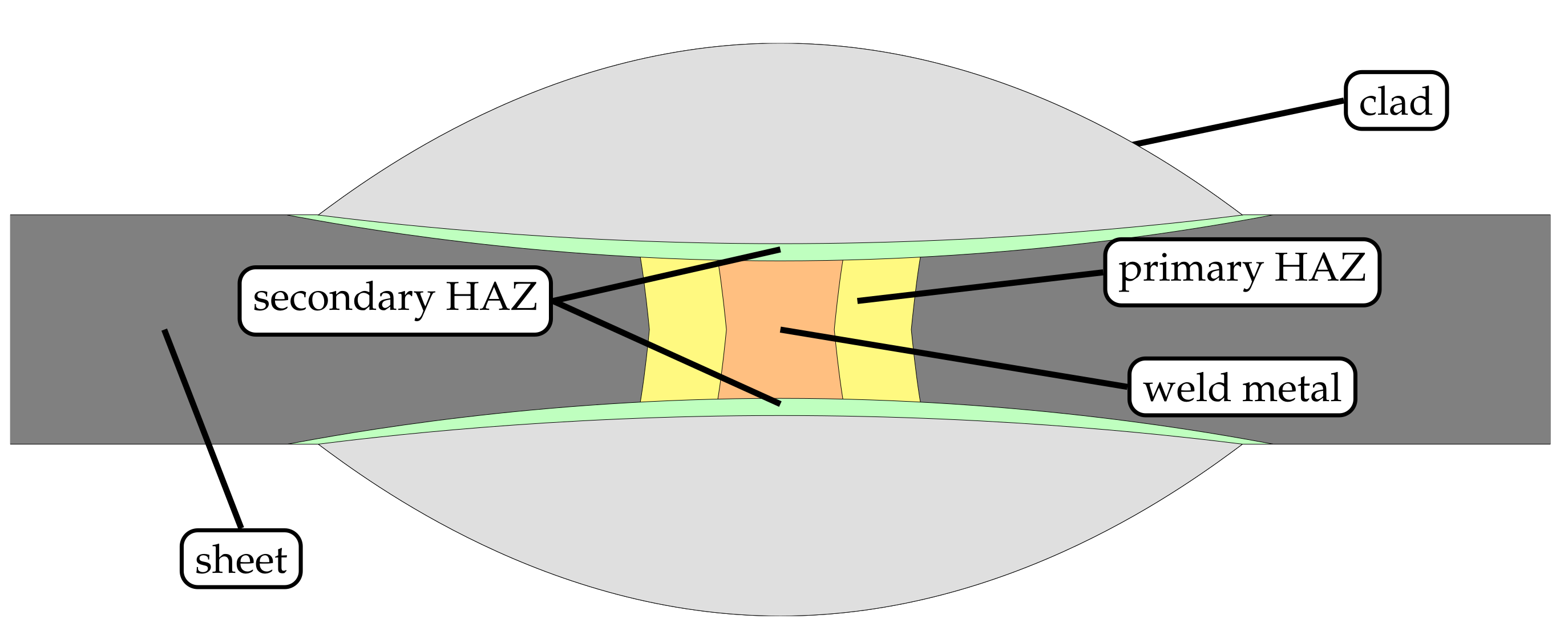
Therefore, the authors of the present study seek to propose an alternative approach to inhibit intergranular corrosion in welds of FSS based on high-speed laser cladding of thin-sheet substrates. Thereby, regions susceptible to selective corrosion along weldments of FSS are coated with a material that is insensitive to localized attack (cf. Figure 1), and a locally operating protection against IGC is established. Based on the speed of the cladding process, this measure can be very well integrated into existing manufacturing lines, whereby significant saving potentials are unlocked.
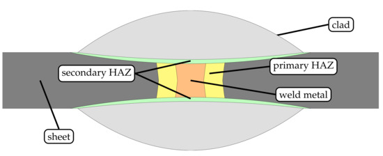
Figure 1.
Schematic detailing the principle of a novel approach to inhibit intergranular corrosion of ferritic stainless steel welds by high-speed laser cladding.
2. Materials and Methods
2.1. Sheet and Powder Materials
As sheet material, unstabilized AISI 430 and titanium-stabilized AISI 430Ti with dimensions of 150 × 100 × were used. The chemical composition of the sheet material is depicted in Table 1 (a). The sheets were laser-welded and laser-cladded in cold-rolled and blank-annealed surface condition.

Table 1.
(a) Chemical composition of AISI 430 and AISI 430Ti sheet material used in the investigation, adopted from [31]. Copyright 2020 Niklas Sommer; (b) Chemical composition of AISI 316L austenitic stainless steel powder, partially adopted from [37]. Copyright 2021 Niklas Sommer.
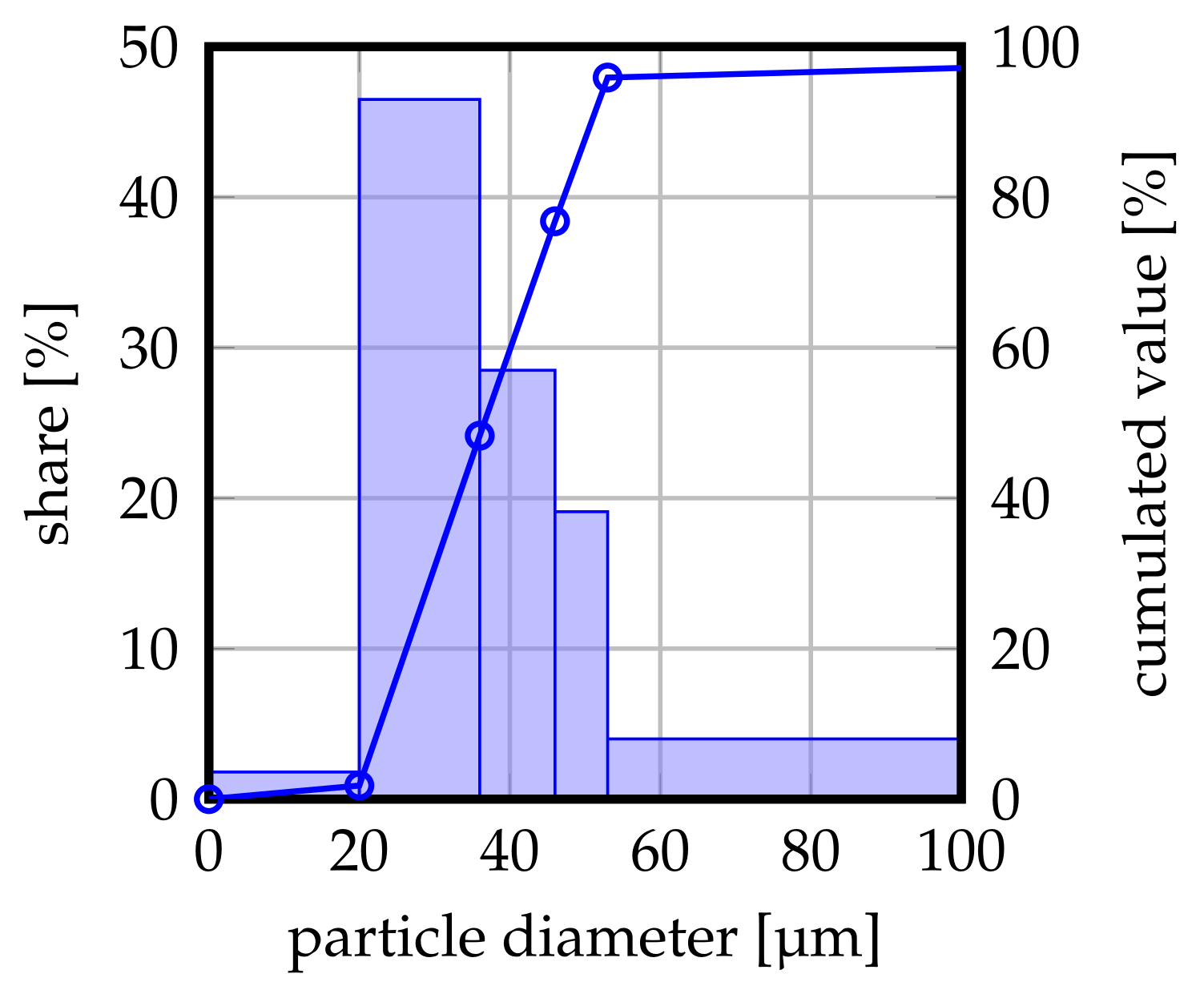
AISI 316L austenitic stainless steel with a nominal powder size distribution of 20– 53 (GTV Verschleißschutz GmbH, Luckenbach, Germany) was employed as feedstock for the laser cladding experiments. A measurement of the respective particle size distribution is illustrated in Figure 2. The chemical composition of the batch is depicted in Table 1 (b).
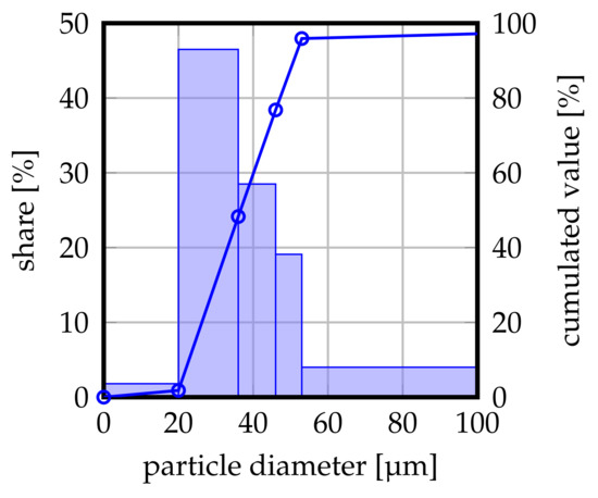
Figure 2.
Particle size distribution of the powder batch used in the present investigation. Nominal distribution 20–53 , partially adopted with permission from ref. [37]. Copyright 2021 Niklas Sommer.
2.2. Laser Welding and High-Speed Laser Cladding
Laser welding and high-speed laser cladding experiments were carried out using a 2 continuous wave ytterbium-fiber-laser (IPG YLS-2000-S2, IPG Laser GmbH, Burbach, Germany) with a nominal wavelength of 1070 and a multi-mode intensity profile. The feed motion was realized through a six-axis robot (Reis RV30-26, KUKA Industries GmbH & Co. KG., Obernburg, Germany). In order to provide for repeatable welding and cladding results, a custom clamping device was used for both, laser welding and laser cladding. For additional information about the clamping device, the reader may be referred to a previous study of ours [31].
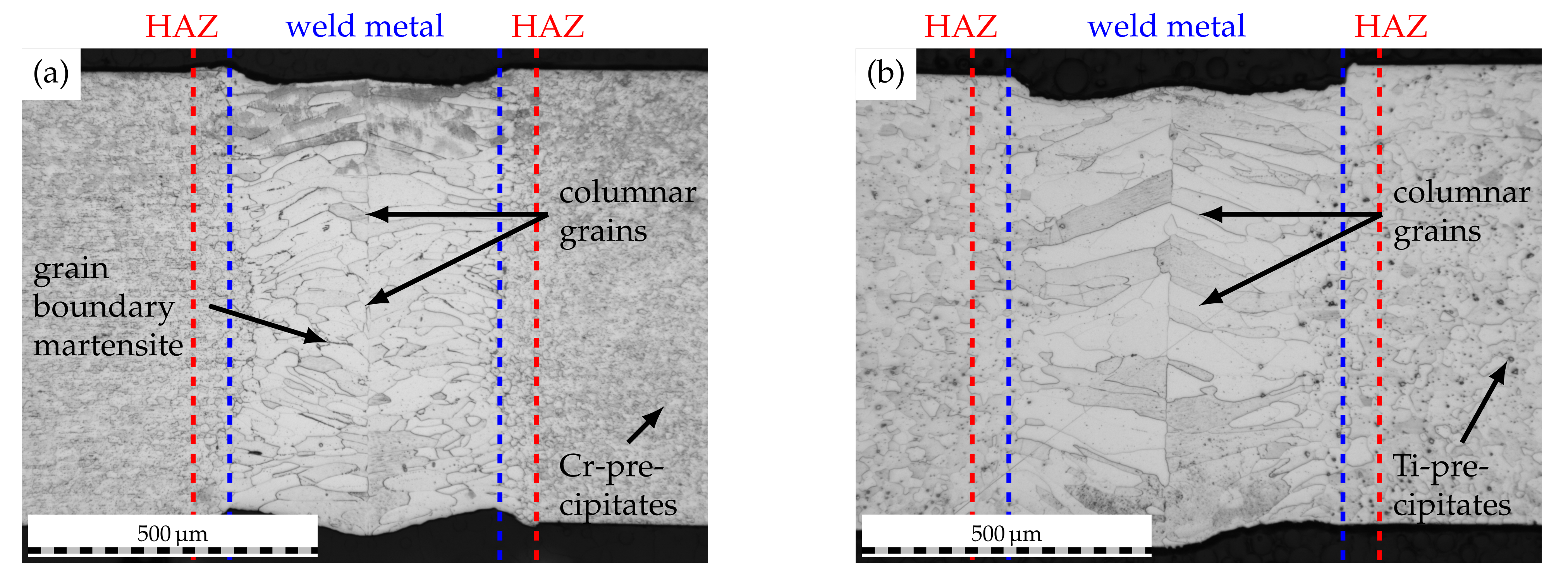
Laser welding experiments were carried out using a laser power of 1201 and a traverse speed of 90 mm·s−1. Through the utilization of modular welding optics (Reis Lasertec MWO44, KUKA Industries GmbH & Co. KG, Aachen, Germany) and a focusing lens with a focal length of 200 , a beam diameter of approximately 200 could be realized on the workpiece surface. Welding was performed in butt-joint configuration as depicted in [31]. To prevent oxidation of the weld seam, argon shielding gas (grade 4.6, purity ≥ %) with a flow rate of 15 L·min−1 was fed through two nozzles to the weld seam top while the seam root was shielded using Argon gas backing (grade 4.6, purity ≥ %) with a flow rate of 5 L·min−1. The use of the aforementioned process parameters yielded weld seam widths of approximately 600 , as can be derived from Figure 3.
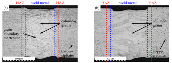
Figure 3.
Initial weld seam macrostructure of (a) AISI 430 and (b) AISI 430Ti. Laser power 1201, welding speed 90 mm·s−1.
For high-speed laser cladding of the thin-sheet substrates, the aforementioned modular welding optics were supplemented by a three-jet, coaxial powder-nozzle (Fraunhofer ILT, Aachen, Germany) with a default standoff distance of 12 . The usage of focusing lenses with focal lengths of 200 and 300 yielded approximate beam diameters of and on the workpiece, respectively. Based on prior investigations on high-speed laser cladding of thin-sheet substrates [37], the nozzle standoff distance was kept at 12 throughout the experiments, while the laser focus was set to the substrate surface. For a continuous powder feed to the cladding optics, a two-disc powder feeder (GTV PF2/2, GTV Verschleißschutz GmbH, Luckenbach, Germany) using argon carrier gas (grade 4.6, purity ≥ 99.996%) at a flow rate of 5 L·min−1 was employed. The powder mass flow was set to 24 g·min−1 for the cladding experiments based on prior investigations [37]. Moreover, argon shielding gas (grade 4.6, purity ≥ 99.996%) with a flow rate of 10 L·min−1 was fed through the coaxial outlet of the powder-nozzle to prevent oxidation of the clad. Through the utilization of laser powers of 1500 and 2000 at a traverse speed of 90 , clad widths of approximately 960 and 1440 could be realized for beam diameters of and , respectively. Thereby, overlaps of approximately 1.6 and 2.4 could be obtained based on the following relation:
where denotes the overlap, b the clad width and the width of the weld seam, including the extension of the heat affected zone (HAZ).
2.3. Corrosion Testing
Corrosion tests were undertaken on the basis of DIN EN ISO 3651-2 (Strauß test) [38]. Prior to corrosion testing, the welded and cladded sheets were cut into samples with dimensions of 100 × 40 and cleaned with a stainless steel brush to remove any residual dirt on the surface. Subsequently, the samples were rinsed with isopropanaol and dried by air. In a glass flask, the samples were contacted with copper chips on the bottom of the latter and immersed in a boiling solution of 138 sulfuric acid ( = /) and 75 copper-sulfate penta-hydrate dissolved in desalinated water to a total solution volume of 750 . Samples were exposed to the corrosive environment for different durations (Table 2), which allowed for a temporally resolved characterization of localized attack. A total of two samples of each type of FSS were tested simultaneously in a glass flask.

Table 2.
Overview of different corrosion testing durations.
2.4. Specimen Characterization
2.4.1. Microstructural Characterization and Microscopy
Microstructural characterization was conducted using etched micrographs prior to and after corrosion testing. For this purpose, the samples were cut perpendicular to the traverse direction using a wet-grinding machine, ground using silicone-carbide paper (grit size 2500), polished with diamond suspension and etched using V2A-etchant. Subsequently, the specimens were inspected by optical microscopy (DM2600, Leica Microsystems GmbH, Wetzlar, Germany). Weld seam observation and fractography analysis was carried out using scanning electron microscopy (SEM, Zeiss REM Ultra Plus, Carl Zeiss AG, Oberkochen, Germany) operated at an acceleration voltage of 15 and equipped with energy dispersive X-ray spectroscopy (EDS, Bruker XFlash 6160, Bruker Corporation, MA, USA). Phase formation and chemical gradients within the cladded cross-sections were inspected using electron backscatter diffraction (EBSD, Bruker -flash, Bruker Corporation, MA, USA) and the EDS/SEM setup mentioned beforehand, which was operated at an acceleration of 20 for these analyses. In order to allow for a non-destructive characterization of intergranular attack prior to mechanical testing, a micro computer tomograph (CT, Zeiss XRadia Versa 520, Carl Zeiss AG, Oberkochen, Germany) with a voxel size of was used.
2.4.2. Mechanical Testing
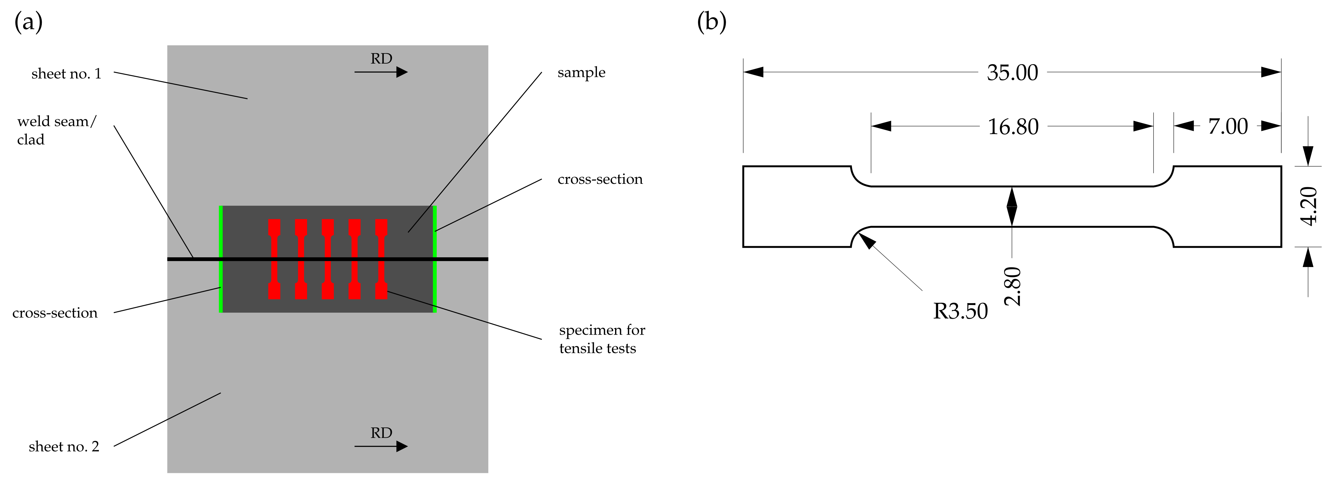
To obtain information about the residual mechanical strength of the welded and cladded joints following corrosive attack, tensile-testing specimens, whose geometry is depicted in Figure 4, were characterized perpendicular to the welding direction by quasi-static tensile tests (Z100, ZwickRoell AG, Ulm, Germany) on the basis of DIN EN ISO 6892-1 [39]. The results were analyzed with respect to the target values of yield strength and elongation at break. The tensile testing specimens were extracted from the previously immersed samples using electric discharge machining (EDM).
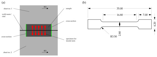
Figure 4.
Schematic depicting (a) sample extraction and (b) specimen geometry employed for tensile-testing, modified with permission from ref. [31]. Copyright 2020 Niklas Sommer.
3. Results and Discussion
3.1. Metallurgy of Laser-Cladded Welds
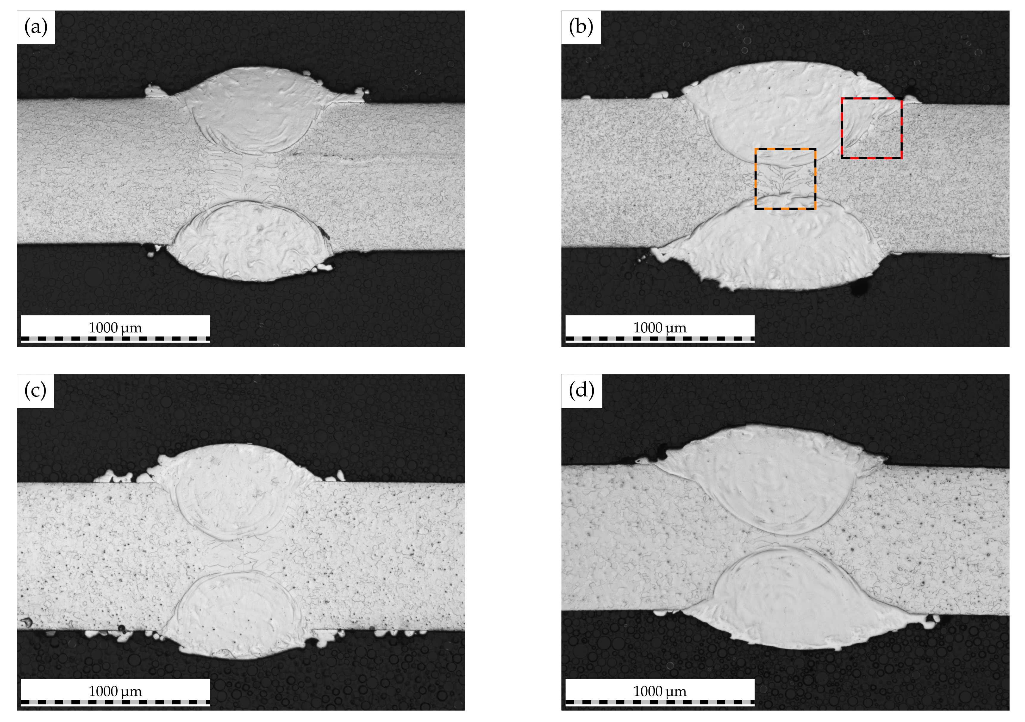
Figure 5 depicts the etched micrographs of the laser-cladded AISI 430 and AISI 430Ti welds. As can be derived from the microscopy images, previously developed process windows for the high-speed laser cladding of thin-sheet substrates [37] could successfully be transferred to the welded substrates and allowed for a reproducible and centrically aligned coating of the weld seam. In addition to the varying clad width, which could be anticipated based on the altering laser beam diameter, a variation in dilution with the substrate material can be detected. When a larger clad width and, thus, overlap such as 2.4 is employed, the dilution with the substrate is increased as compared to samples cladded with an overlap of 1.6. In light of the higher laser power employed, which is needed to obtain enlarged clad widths, these observations seem appropriate. Despite dilution with the substrate, it has to be noted that for all investigated materials and overlaps, a clear separation between the ferritic weld metal and the austenitic clad is identifiable.
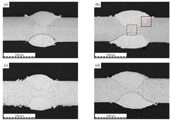
Figure 5.
Etched micrographs depicting the weld macrostructure of laser-cladded (a,b) AISI 430 and (c,d) AISI 430Ti. Left: overlap 1.6, right: overlap 2.4. Colored rectangles mark ROI for further investigation.
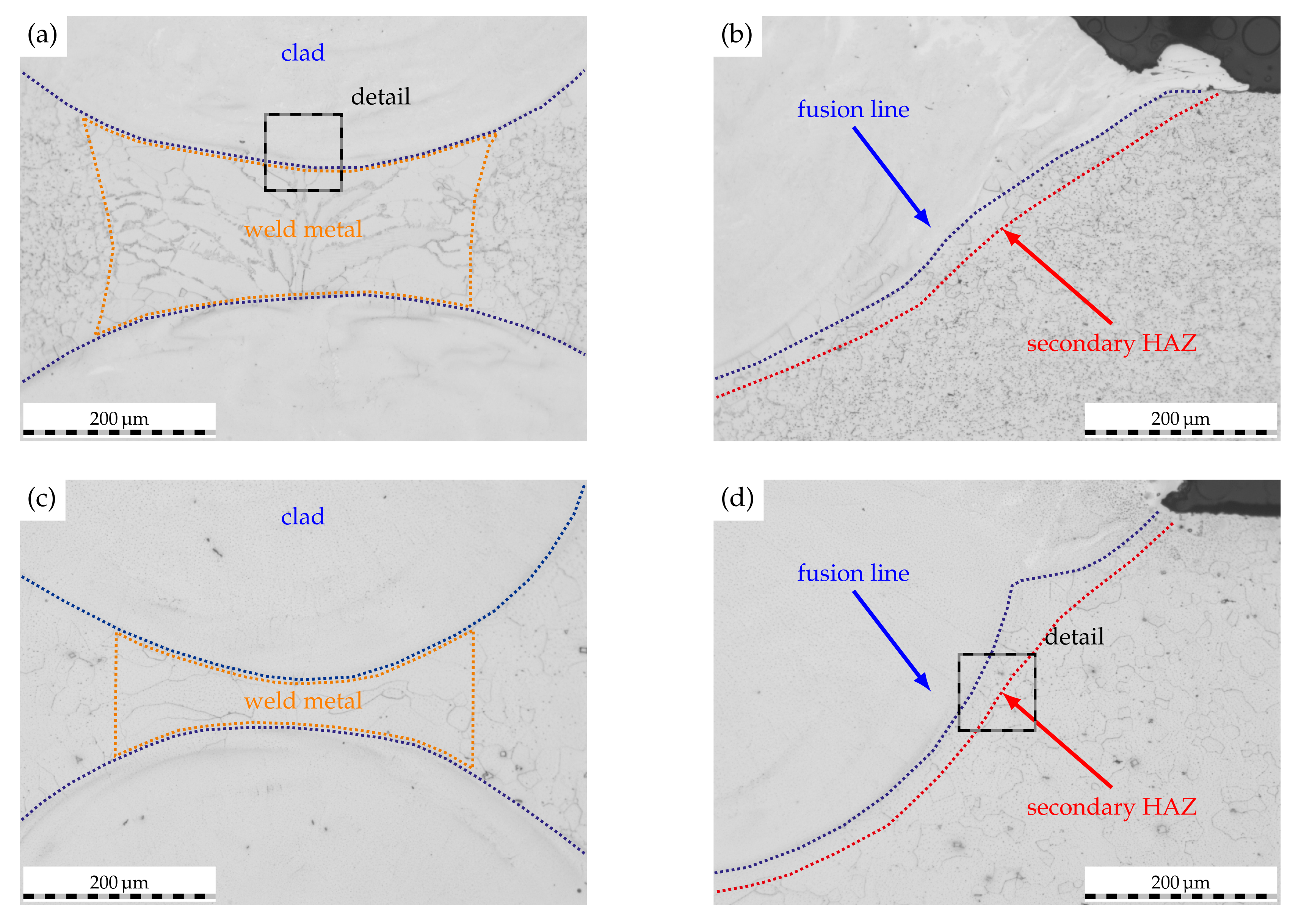
Based on these observations, two regions of interest were further characterized by optical microscopy, as is shown in Figure 6. The clear separation of clad and weld metal identified beforehand is further supported by the micrographs of AISI 430 (cf. Figure 6a) and AISI 430Ti (cf. Figure 6c). In both cases, it is evident that some of the initial weld metal is liquefied during the laser-cladding process to form a distinctive, alloyed region. Such in situ alloying can frequently be observed when utilizing laser-based directed energy deposition processes (DED-LB) due to the inherent process characteristics [40]. However, the reaction of the employed etchant suggests a drastically different composition than the weld or base metal. In consequence of the initial weld microstructure (cf. Figure 3), the laser-cladded weld metal of AISI 430 features some grain boundary martensite while the AISI 430Ti weld metal exhibits a solely ferritic microstructure.
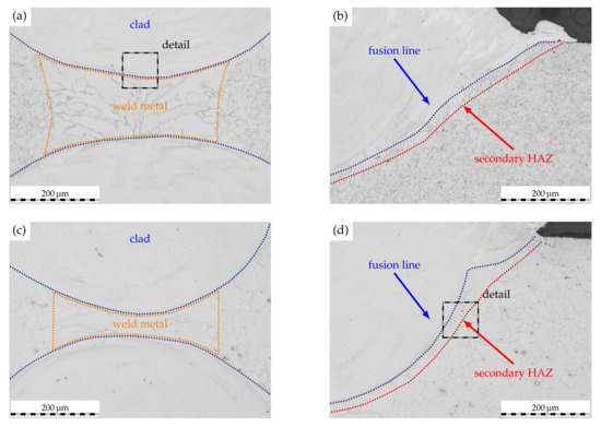
Figure 6.
Etched micrographs of ROI along the clad–weld interface as marked in Figure 5. (a,b): AISI 430, overlap 2.4. (c,d): AISI 430Ti, overlap 2.4.
Adjacent to the fusion line, a very narrow secondary HAZ can be identified, whose emergence was anticipated based on the presented novel approach to inhibit IGC in ferritic stainless steel welds. Regardless of the substrate material, the secondary HAZ is characterized by a seam with a width of about 20 , in which carbides or nitrides are seemingly dissolved (cf. Figure 6b,d). In contrast, these carbides or nitrides are finely dispersed within the unaffected base material bordering the secondary HAZ. Moreover, some grains within the fusion zone of the clad solidify as ferrite grains based on the observations of the etched microscopy images. Therefore, combined EBSD and EDS analyses were carried out to verify the phase formation along the clad–weld metal and clad–base metal interfaces.
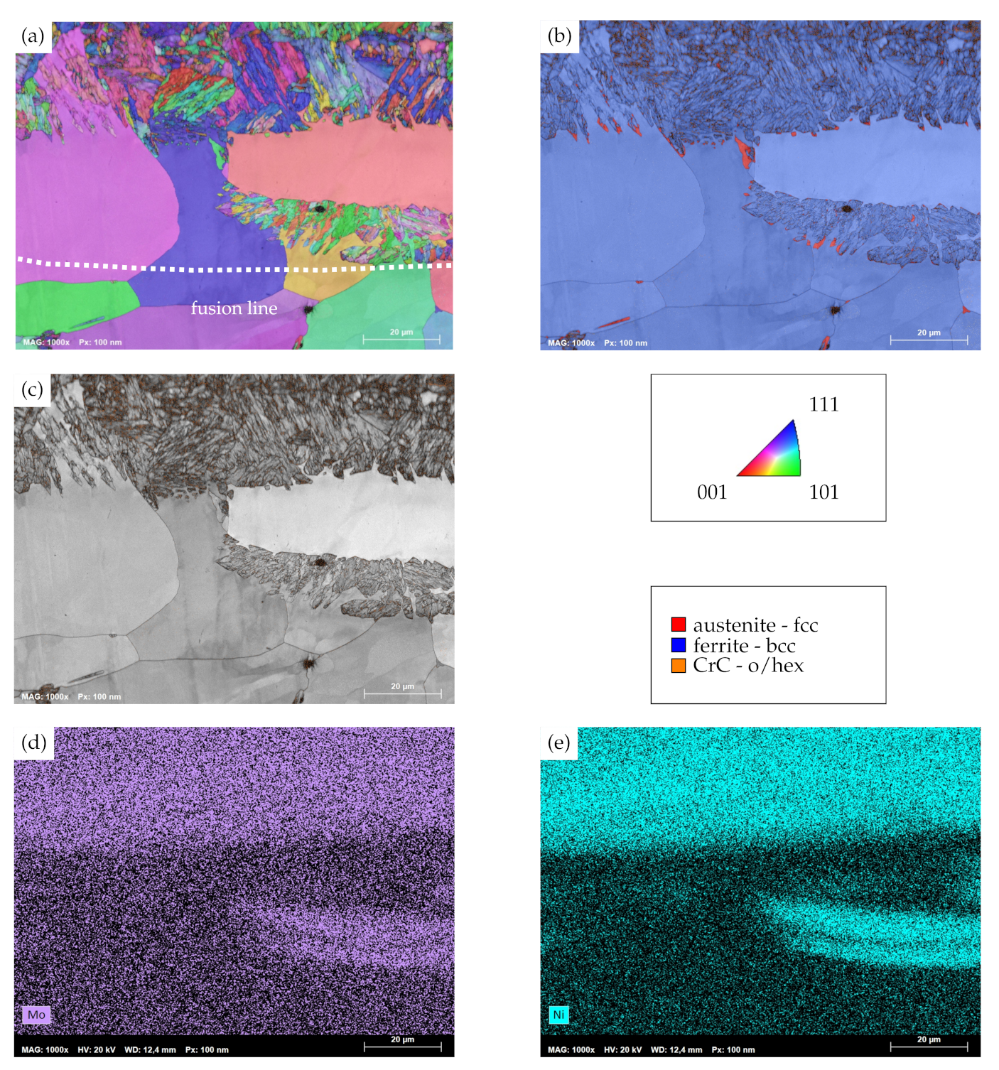
Figure 7a depicts the inverse pole figure mapping (IPFM) and superimposed image-quality mapping (IQM) of the transition zone between weld metal and clad of AISI 430 substrates. As can be derived from the mapping, the transition region is characterized by two distinct microstructural features. On the one hand, columnar grains within the weld metal can be seen, which originate from the welding process and thus were to be expected based on its microstructural evolution. On the other hand, substantially smaller grains with a different morphology and alternating grain orientation are to be seen at the weld metal–clad interface. Moreover, these grains also emerge in the midst of some of the columnar grains of the weld metal, for which the depicted region obviously lies within the fusion zone of the cladding process. Despite the different morphology of the grains, the combined phase mapping (PM) and image quality mapping in Figure 7b reveals a body-centered cubic (bcc) lattice structure for both identified grain morphologies. A limited number of grains within the plate-shaped regions are decorated with face-centered cubic (fcc) phases at the grain boundaries. As the precipiation of chromium carbide is decisive with respect to the corrosion resistance of unstabilized FSS, Figure 7c is used to evaluate the presence and location of orthohomic (o) and hexagonal (hex) chromium carbide phases. As the combined IQM/PM demonstrates, these chromium carbides are predominantly found within the previously identified, plate-shaped bcc-phases in the transition region. In light of the altering morphology of the bcc-phases, it is unclear why orthohombic and hexagonal chromium carbide tend to segregate around the plate-shaped bcc-phase. In consideration of the findings presented by Nowell et al. [41], the EBSD analysis in the present investigation may not distinguish bcc-ferrite and distorted body-centered-martensite correctly due to their similar lattice parameters. In addition, the morphology of the plate-shaped phases are rather alike the results of an EBSD analysis of martensite [41]. As martensite is typically not present within DED-processed AISI 316L [37] and may only be detected at grain boundaries within the weld metal of AISI 430 [31], only an incumbent chemical gradient of the transition zone could lead to a partial phase transformation. Hence, an EDS analysis of the respective region was carried out. As indicators for the EDS mappings, molybdenum and nickel, which are incorporated in AISI 316L to a larger extent than in AISI 430, are used. Figure 7d,e depict the EDS mappings of molybdenum and nickel, respectively. It is to be seen that the bcc-phase, plate-shaped regions of the weld metal–clad interface exhibit substantially stronger signals of molybdenum and nickel than the columnar bcc-ferrite grains. With respect to the chemical composition of the initial materials, this chemical gradient can be explained by the in situ alloying of substrate and clad, as AISI 430 in the present study is scarce in both molybdenum and nickel. The segregation of the latter two within the observed region can be attributed to the melt pool dynamics of the cladding process. As a result of this, it is appropriate to conclude that the present chemical gradient allows for the observed phase transformation. In anticipation of an evaluation of corrosion resistance, it has to be noted that the presence of martensite is important for the accommodation of excess carbon, which may not readily form grain boundary carbides and thus IGC resistance of FSS [22]. The present findings suggest that the identified, plate-shaped bcc-phases incorporate martensite and thus act as a reservoir for excess carbon, which is further supported by the segregation of orthohombic and hexagonal chromium carbide within these grains.
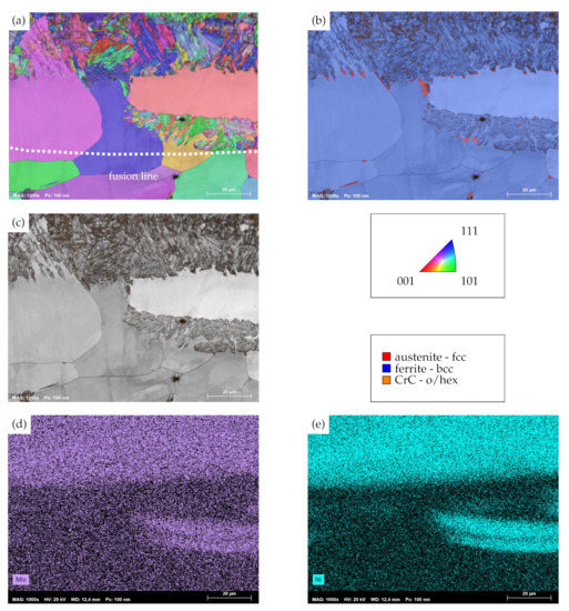
Figure 7.
(a) Combined image-quality mapping (IQM) and inverse pole figure mapping (IPFM) of the clad–weld metal transition zone of AISI 430 with an overlap of 2.4. (b) Combined IQM- and phase mapping (PM), (c) IQM with singular display of orthohombic/hexagonal chromium-carbide phases. Orientations in IPFM plotted perpendicular to traverse direction. (d) EDS-map for molybdenum and (e) EDS-map for nickel.
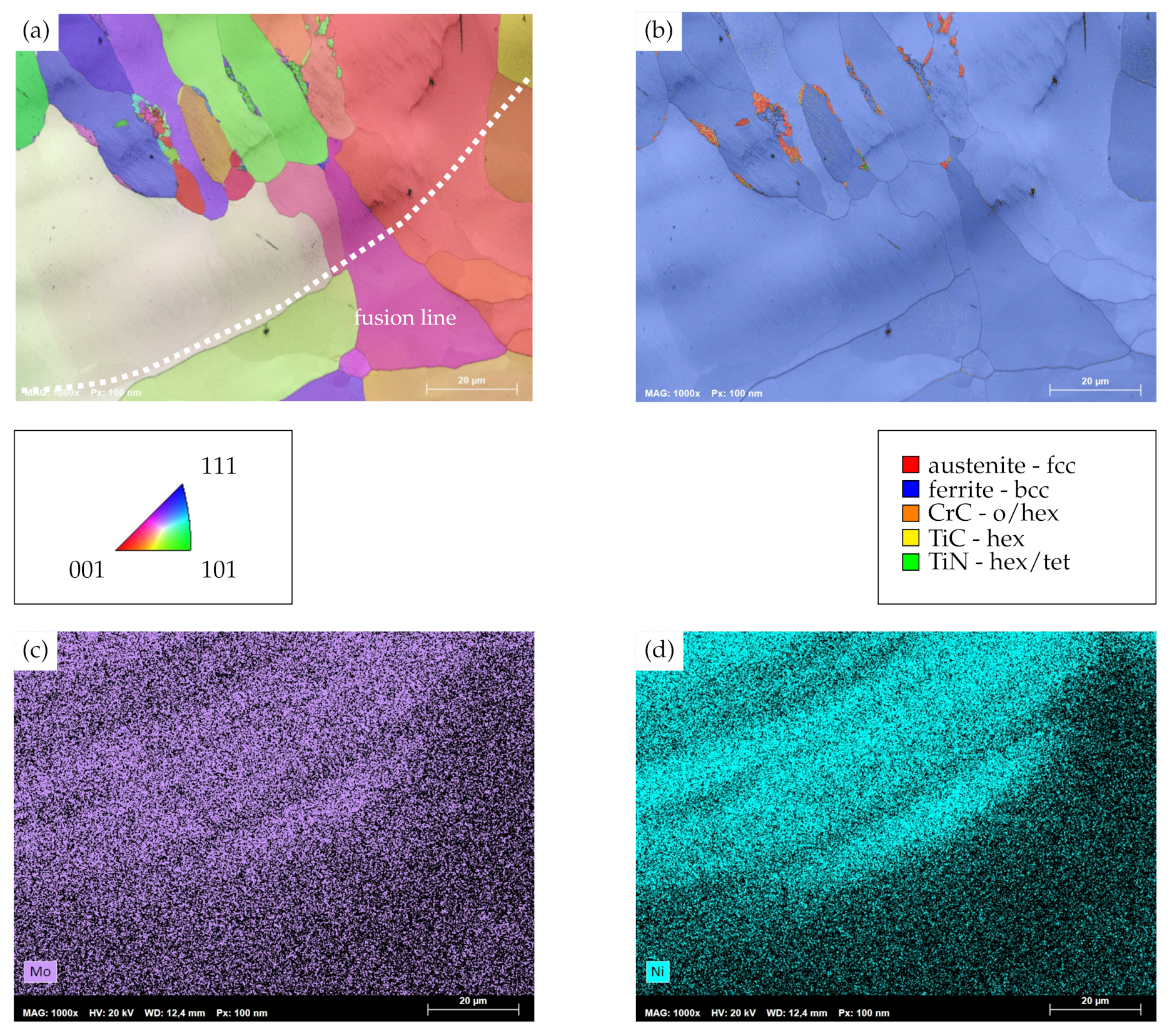
A somewhat different behavior is identified for the transition zone of AISI 430Ti, as superimposed IQM and IPFM as well as PM in Figure 8a,b visualize. While similar chemical gradients to the AISI 430 substrate with increasing contents of molybdenum and nickel are to be seen seen (cf. Figure 8c,d), the depicted transition zone lacks the distinctively alternating microstructural morphologies which had been observed previously. Rather, grains within the clad exhibit a preferential orientation and grow perpendicular to the fusion line. The latter can be seen in good agreement to results of Helmer et al. [42] on the electron beam melting processes, where the temperature gradient and, thus, the direction of grain growth are oriented perpendicular to the melt pool boundaries. A similar grain growth direction within single tracks of AISI 316L on AISI 316L substrates has recently also been reported on by Kiran et al. [43]. In addition to that, no plate-shaped martensite in the transition region can be identified. Only a few, comparatively small grains decorate the grain boundaries of the aforementioned directionally solidified crystals. In contrast to the surrounding matrix, which exhibits a bcc-ferrite lattice structure, these small grains solidify as fcc-austenite and incorporate some hexagonal titanium carbide as well as hexagonal and tetragonal (tet) titanium nitride. Obviously, the formation of these precipitates within the clad geometry can be attributed to the dilution of laser-cladded AISI 316L with the titanium-containing AISI 430Ti and subsequent precipitation during the thermal cycle of laser cladding. However, it has to be noted that neither of these precipitates emerge within the secondary HAZ or at grain boundaries within the clad geometry which are located farther away from the fcc-austenite phases. Therefore, it is appropriate to conclude that dilution with the substrate is limited to nearby regions of the clad.
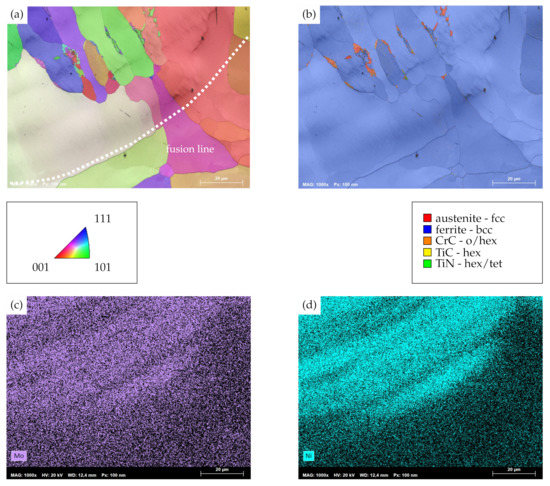
Figure 8.
(a) Combined IQM and IPFM of the clad–base metal and weld metal transition zone of AISI 430Ti, laser-cladded with an overlap of 2.4. (b) Combined IQM and PM. Orientations in IPFM plotted perpendicular to traverse direction. (c) EDS-map for molybdenum and (d) EDS-map for nickel.
From the metallurgy results presented beforehand, it can be derived that the use of high-speed laser cladding on thin-sheet substrates of laser-welded FSS facilitated substantial mixing of clad and substrate as well as phase transformations with incumbent precipitation phenomena. As these mixing and precipitation phenomena are of the utmost importance to corrosion resistance, the following paragraph shall discuss and relate these findings to the IGC resistance of the clad–weld joint.
3.2. Influence on Corrosion Resistance
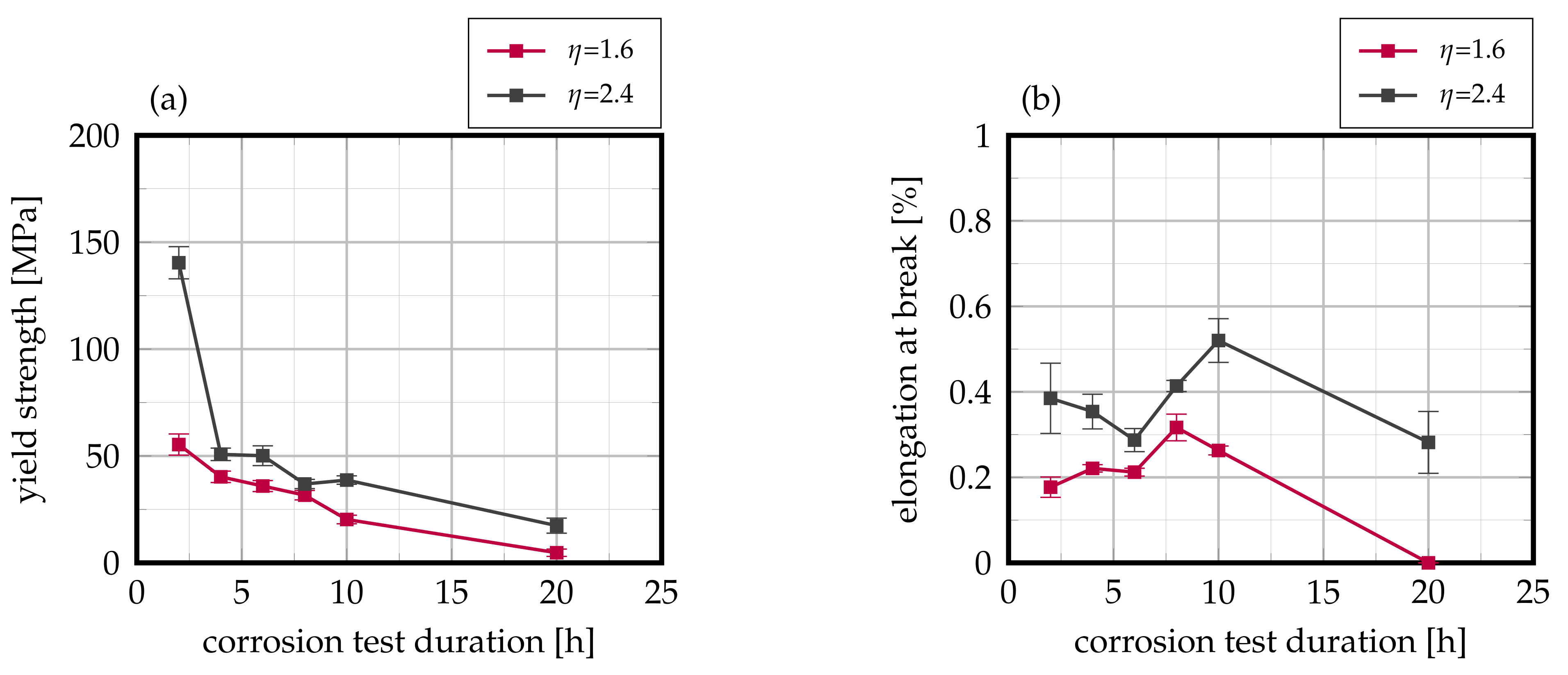
The laser-cladded welds were subsequently exposed to the Strauß-test in boiling 16% sulfuric acid solution, and their residual mechanical strength was analyzed by means of tensile tests with special consideration of the target values yield strength and elongation at break. As can be derived from Figure 9, laser-cladded AISI 430 FSS exhibits a pronounced interdependency of residual mechanical strength to exposure duration in the corrosive environment as well as to the weld seam overlap. After a corrosion duration of 2 , the residual yield strength is reduced to 140 for an overlap of 2.4. In contrast, when an overlap of 1.6 is used, the residual yield strength only amounts to 55 . This interrelationship is carried on over varying exposure durations up to 20 . Here, the residual yield strength only accounts for and for overlaps of 2.4 and 1.6, respectively. For both investigated overlaps, the residual yield strength demonstrates an approximate exponential decline with respect to increasing exposure duration. On the contrary, no such behavior can be identified for the target value of residual elongation at break, as Figure 9b visualizes. No pronounced interdependency of elongation at break and exposure duration is detectable as all tested samples feature failure strains of less than 1%, which—in combination with the results of residual yield strength—suggest brittle fracture as a result of presumable corrosion propagation. This observation is further supported by the fact that all samples exhibited failure within the cladded joint.
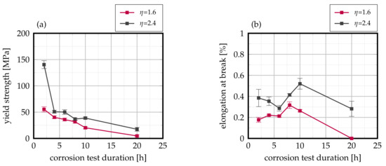
Figure 9.
Evolution of (a) yield strength and (b) elongation at break in dependency on the corrosion testing duration of laser-cladded AISI 430. Mean values of 12 samples each, error bars represent standard error of the mean.
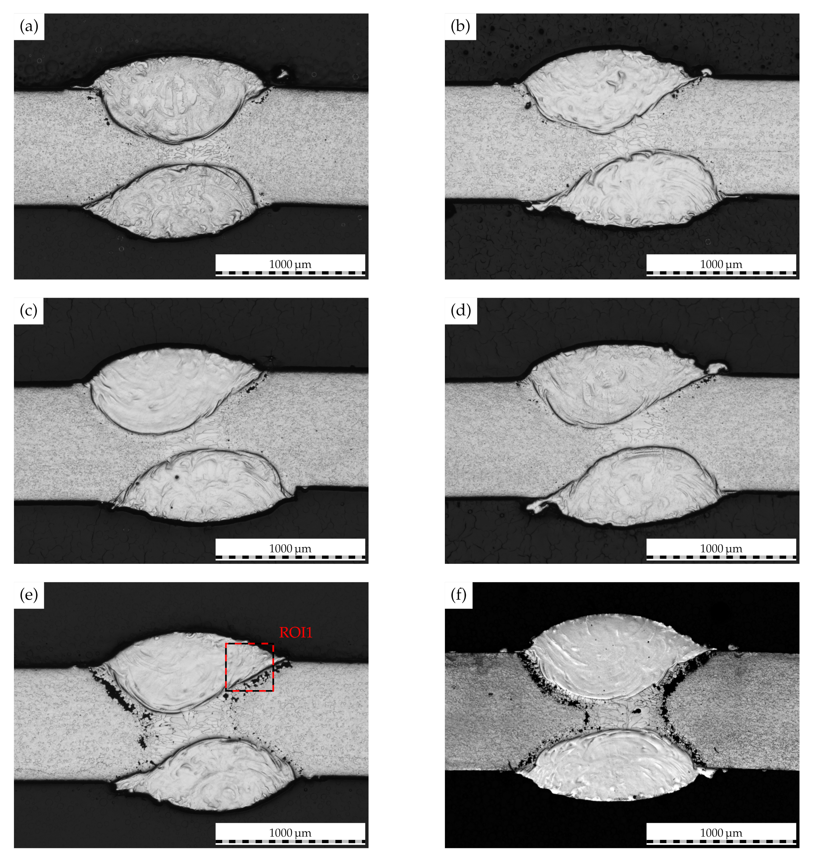
The temporally resolved illustrations of the cladded weld seam cross-sections in Figure 10 demonstrate the time-dependent propagation of IGC in cladded joints of AISI 430. While only minor attack is seen after a test duration of 2 , the intergranular attack is consequently intensified with an increase in test duration to 20 . Here, IGC is propagated along the clad–base metal interface to the initial weld metal. These microstructural features thus correspond well to the mechanical analysis in the preceding paragraph.
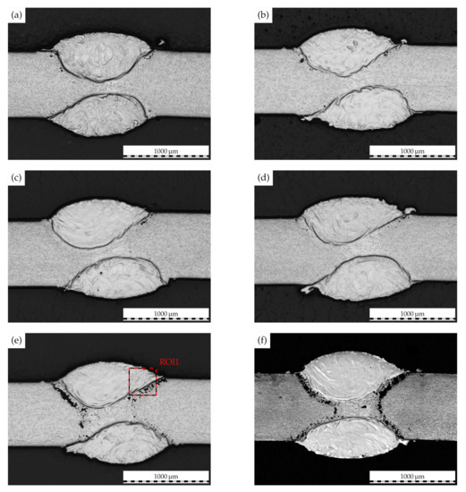
Figure 10.
Laser-cladded weld macrostructure of AISI 430 following corrosion testing for (a) 2, (b) 4, (c) 6 (d) 8, (e) 10 and (f) 20. Overlap 2.4. Colored rectangle represents ROI for further investigation.
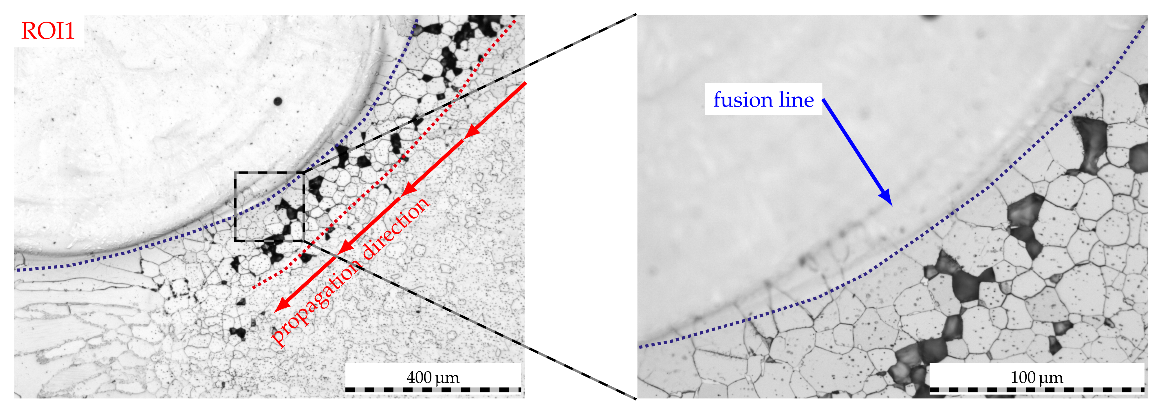
The etched micrographs of a 10 sample in Figure 11 shed light on the underlying mechanisms. Evidently, IGC can be identified in the HAZs of this unstabilized FSS following exposure to boiling sulfuric acid. As can be seen in region of interest 1 (ROI1), IGC is propagated along the secondary HAZ of the cladding process to ultimately reach the primary HAZ of the welding process. Here, IGC does also penetrate the weld metal due to chromium depletion as reported in [32]. However, IGC cannot overcome the interface of the fusion line in the detail of Figure 11. Moreover, grain boundaries in proximity to the clad matrix feature less intergranular attack than grain boundaries which are farther away from the fusion line of the clad. In light of the combined EBSD and EDS analysis presented beforehand, this affirms that the distorted bcc-phase of the clad as well as the plate-shaped bcc-phases act as a reservoir for excess carbon of adjacent ferrite grain boundaries, for which the former may not demonstrate as pronounced chromium carbide precipitation at grain boundaries within the ferrite matrix and, thus, decreased degrees of sensitization.
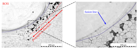
Figure 11.
Etched micrographs of a laser-cladded AISI 430 weld seam following corrosion testing. Exposure duration 10, overlap 2.4. ROI analog to markings in previous figure.
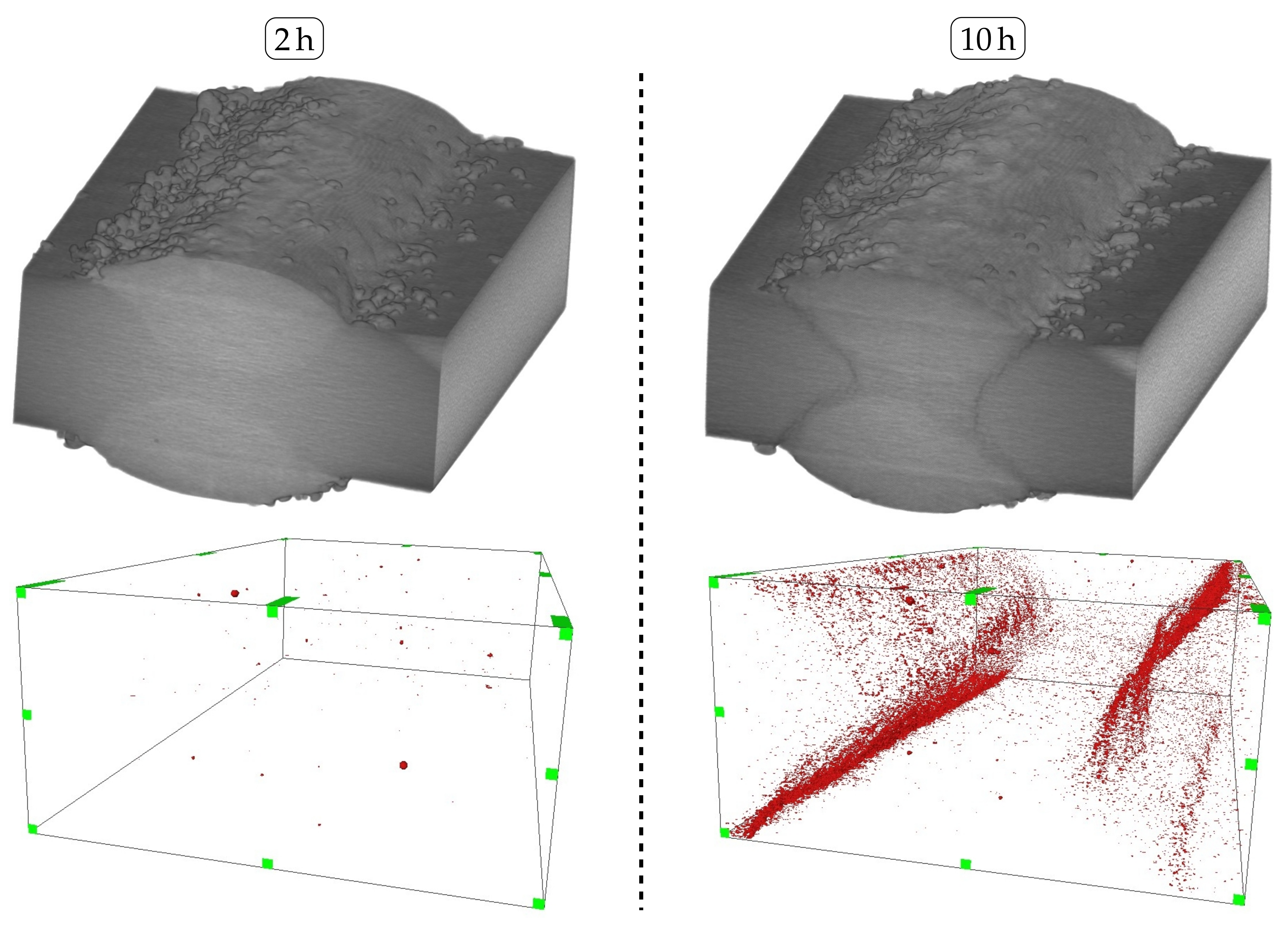
Nonetheless, it is apparent that only a few sensitized grain widths along the secondary HAZ of the cladding process are sufficient enough to induce IGC propagation along these grain boundaries. In consideration of the altering yield strengths identified for varying overlaps, it can be concluded that a larger overlap leads to a farther distance along the secondary HAZ, which needs to be penetrated by IGC before reaching the primary HAZ of the welding process. Therefore, samples cladded with an overlap of 2.4 feature improved tensile properties throughout increasing exposure durations as compared to an overlap of 1.6. In addition, the observed increase in the dilution as a result of higher laser power and, subsequently, heat-input, of an overlap of 2.4 therefore plays a subordinate role in the IGC resistance of laser-cladded, unstabilized FSS. On top of that, the non-destructive -CT analysis in Figure 12 affirms the spatial propagation of IGC along the secondary HAZ of the laser-cladded samples to ultimately reach the primary HAZ of the welding process. As was assumed prior based on the investigation of etched micrographs, intergranular attack is significantly reduced when the sample is exposed for a duration of 2 .
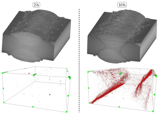
Figure 12.
Top: Reconstructed -CT-models of laser-cladded AISI 430 following corrosion testing for 2 and 10. Bottom: Inverted illustration depicting excavations along the weld seam and clad interface. Overlap 2.4.
Despite the identification and insufficient avoidance of IGC in unstabilized AISI 430 FSS, it can be deduced that the residual mechanical strength of such laser-cladded joints is superior to the residual mechanical strength of solely welded joints, which exhibit rapid and cataclysmic failure [31].
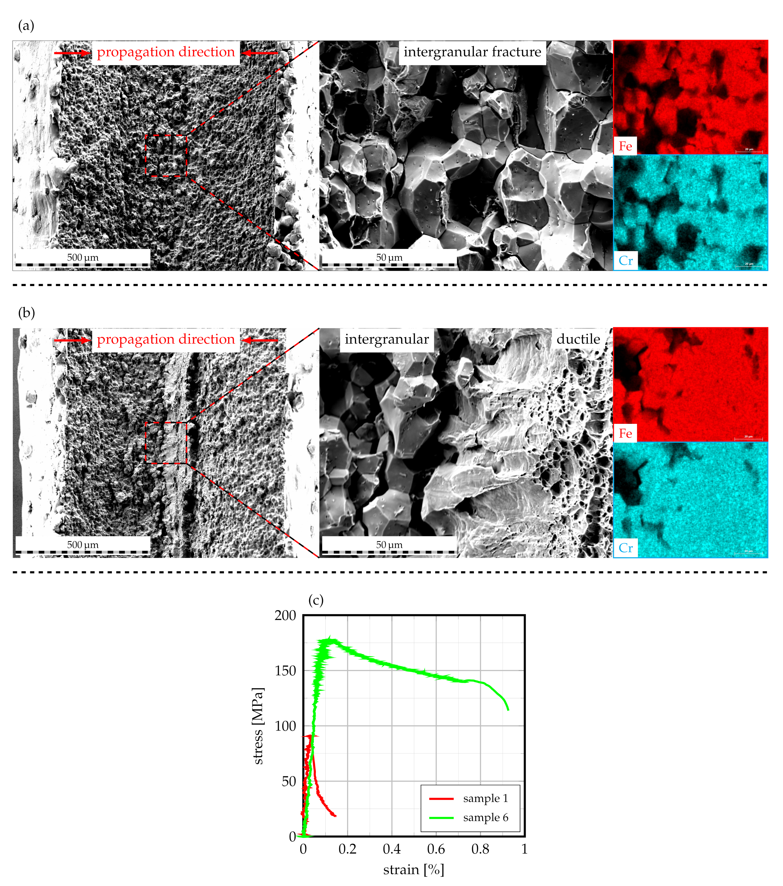
For further characterization, samples with highest and lowest values of yield strength following a corrosion duration of 2 were subjected to fractography analysis by means of SEM in order to investigate the fracture mechanism. As can be derived from Figure 13a, sample 1, whose tensile properties are depicted in Figure 13c, exhibits intergranular fracture along degraded grain boundaries. From the appended EDS-maps, which indicate strong signals for iron and chromium, it can be deduced that the fracture is propagated through the secondary and primary HAZ in the ferritic matrix as a result of full IGC penetration.
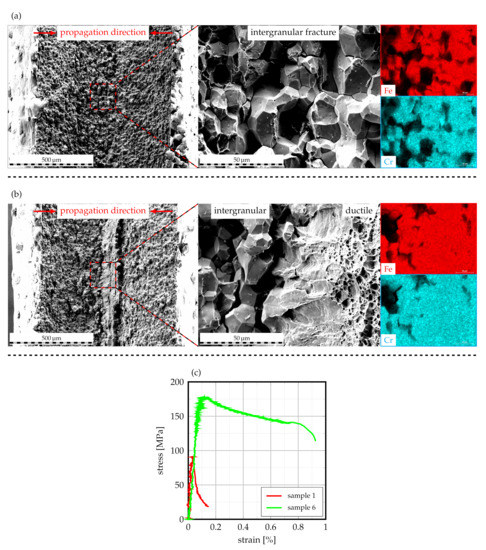
Figure 13.
SEM fractography images of laser-cladded AISI 430 with corresponding EDS maps of the fracture surfaces: (a) sample 1, (b) sample 6, (c) stress–strain curves of the respective samples.
In contrast, sample 6, which features a substantially increased yield strength and elongation at break (cf. Figure 13c), exhibits an alternative fracture surface with some intergranular and some ductile fracture features, as Figure 13b visualizes. Given the obtained tensile properties, it can be deduced that the remaining ductile features are responsible for the improved tensile properties of this sample. Analog to sample 1, the EDS-maps are characterized by strong signals for iron and chromium. In this case, IGC has obviously not penetrated the entire sheet thickness along secondary and primary HAZ, for which the uncorroded areas of the weld demonstrate ductile fracture.
In consideration of the fact that both samples were extracted from a singular cladded weld, it can be concluded that IGC may find preferential sites along the cladded weld seams HAZs, which is to be seen in congruence to the -CT findings presented beforehand. Despite the fact that IGC cannot be fully prevented through the use of high-speed laser cladding along weldments of unstabilized FSS, it is evident that the residual tensile properties are somewhat improved. Based on the altering joint strengths for different overlaps, it seems appropriate to deduce that a further increase in overlap may enhance the mechanical properties of the joint as the IGC propagation distance along the secondary HAZ is increased.
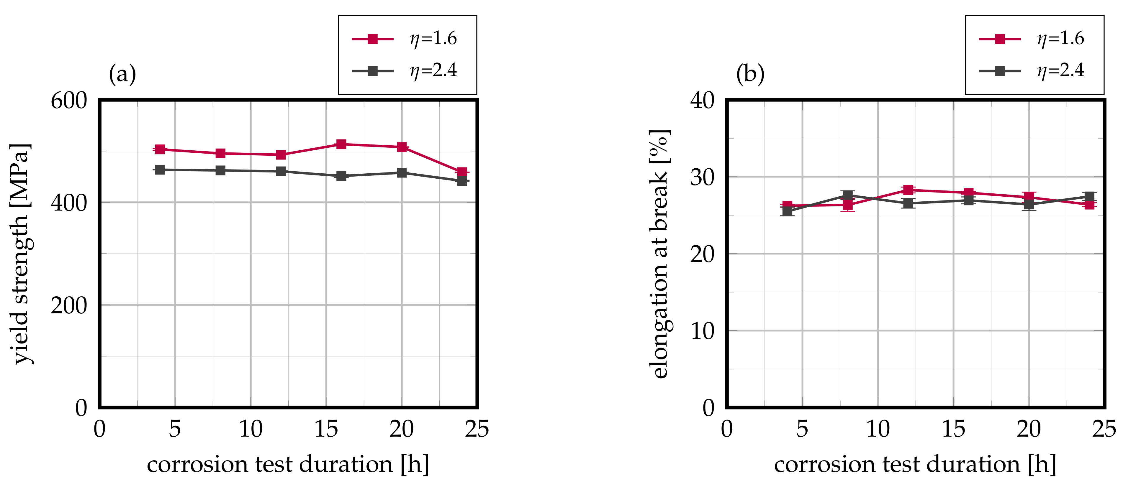
With respect to the titanium-stabilized grade AISI 430Ti, no pronounced interdependency of residual mechanical strength and exposure duration to the corrosive environment can be identified, as Figure 14 visualizes. This foreshadows a full and successful prevention of IGC. Moreover, it needs to be noted that fracture within the tested tensile samples occurred outside the weld seam area and within the base material at all times. Therefore, the measured mechanical properties represent those of the actual sheet and further the idea that the weld seam is not the weak point of the joint anymore.
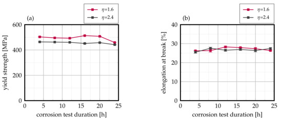
Figure 14.
Evolution of (a) yield strength and (b) elongation at break in dependency on corrosion testing duration of laser-cladded AISI 430Ti. Mean values of 12 samples each, error bars represent standard error of the mean.
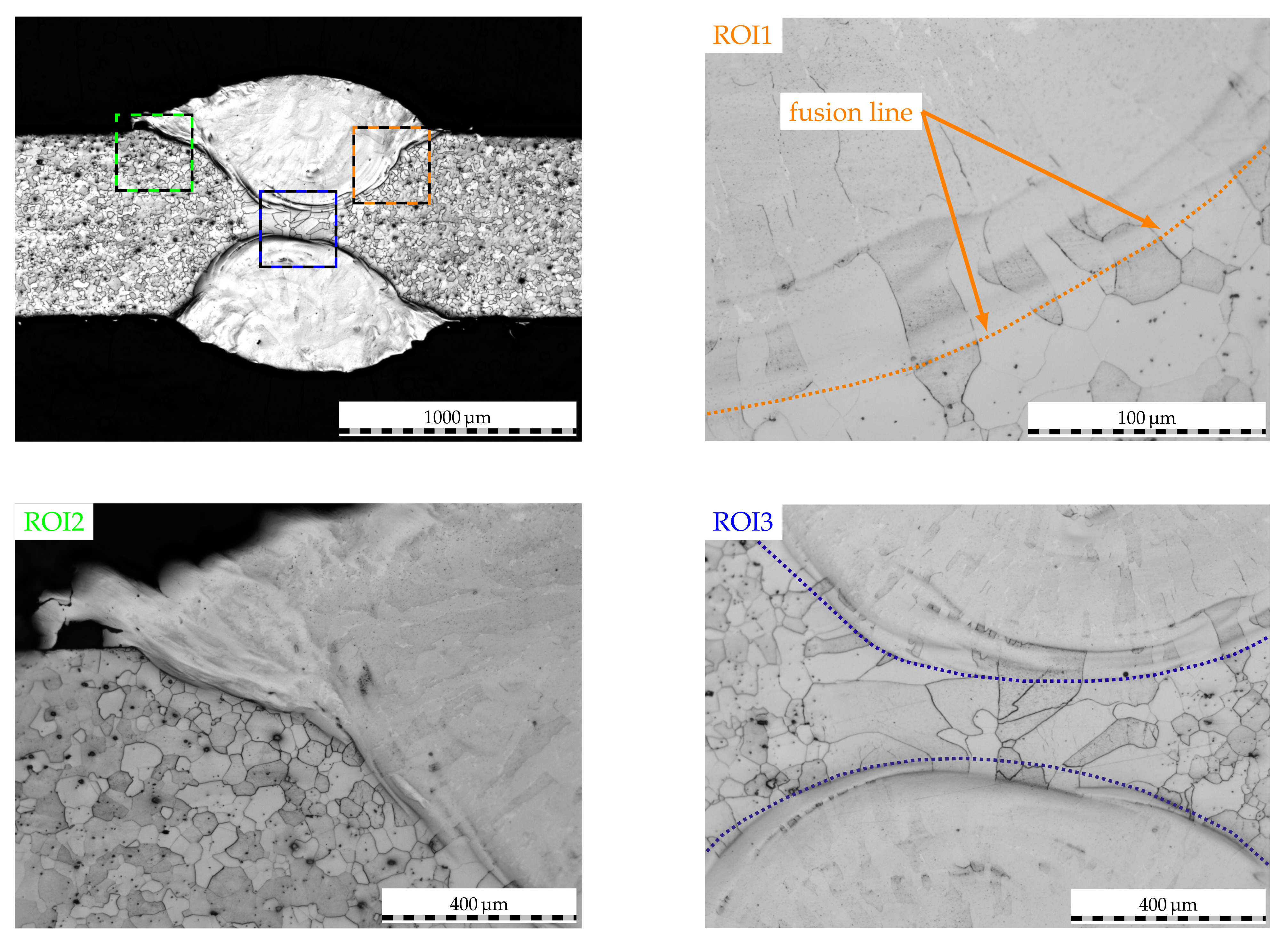
The aforementioned theory is further supported by the post-mortem cross-section of the cladded weld seam in Figure 15. Here, no signs of IGC can be detected—neither along the fusion line and secondary HAZ (ROI1) nor along the clad–sheet interface (ROI2) or the clad–weld metal transition (ROI3). A deeper investigation of the clad cross-section reveals that no titanium nitrides, which have proved to be detrimental to corrosion resistance when reaching the weld surface [32], are carried within. Therefore, corrosive attack cannot penetrate the weld metal through these local galvanic couples for which the corrosion resistance is substantially increased. In addition to that, the results demonstrate that IGC along partially oxidized titanium carbides on top of the weld bead is fully prevented due to the austenitic laser-cladding and subsequent coating of vulnerable sites. In view of the precipitation phenomena at the clad–sheet interface of this titanium-stabilized FSS, which was characterized using EBSD and EDS analyses in the preceding section, it can be concluded that these phenomena are restricted to the dilution zone and do not affect the corrosive properties of the clad–weld joint. Based on the investigation of the secondary HAZ along the clad, no other detrimental IGC phenomena such as knife-line attack can be identified. Thus, the secondary thermal cycle imposed by the cladding process is nonhazardous to the corrosion resistance as obviously no titanium containing grain boundary carbides are dissolved and, subsequently, no further precipitation of chromium carbide can occur. The latter is to be seen in excellent agreement to the EBSD findings presented beforehand.
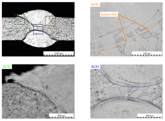
Figure 15.
Etched micrographs of a laser-cladded AISI 430Ti weld seam following corrosion testing. Exposure duration 20, overlap 2.4. Colored rectangles represent ROI for further inspection.
4. Conclusions
In the present study, a novel approach to inhibit IGC in ferritic stainless steel welds through the utilization of high-speed laser cladding was presented. The microstructural evolution and in situ alloying of the clad–weld interface was thoroughly investigated using optical microscopy and EBSD and EDS analyses. From the shown results, it can be deduced that the segregation of alloy elements poses a significant influence on phase formation and, thus, precipitation characteristics within the fusion zone. Moreover, the secondary HAZ of the cladding process is identified as a seam of only few grains in width. Nonetheless, the sensitization of these grain boundaries due to chromium carbide precipitation is sufficient to induce IGC in unstabilized AISI 430 FSS. Despite that, it is evident that high-speed laser cladding does possess a positive influence on residual mechanical strength of the joint, as IGC needs to propagate along the secondary HAZ, for which the time until ultimate joint failure is enlarged. As a result of this interdependency, welds cladded with a comparatively larger overlap feature superior residual mechanical strength as compared to welds cladded with a smaller overlap throughout the study. In contrast, IGC phenomena in titanium stabilized AISI 430Ti FSS can be avoided completely due to the omittance of titanium nitride and titanium carbide precipitation within the clad, for which these cannot segregate and act as localized galvanic couples or be partially oxidized. Given the high traverse speeds of the presented approach, it may be integrated very well in existing manufacturing lines and thus unlock substantial cost-saving potentials. Moreover, it incorporates the first locally employable approach to inhibit IGC in ferritic stainless steel welds.
Author Contributions
Conceptualization, N.S.; methodology, N.S.; validation, N.S. and S.B.; formal analysis, N.S.; investigation, N.S., L.G. and C.W.; resources, S.B.; data curation, N.S.; writing—original draft preparation, N.S.; writing—review and editing, N.S. and S.B.; visualization, N.S.; supervision, S.B.; project administration, N.S.; funding acquisition, S.B. All authors have read and agreed to the published version of the manuscript.
Funding
The shown results were achieved in the project “Kombiniertes in-situ Laserstrahl-/Lasers- trahlauftragschweißen bei nichtrostenden Stählen zum Schutz vor interkristalliner Korrosion” (reference IGF 20.129N), which is supervised by the Forschungsvereinigung Schweißen und verwandte Verfahren e.V. of the German Welding Society and funded by the German Federation of Industrial Research Associations (AiF) by means of the Federal Ministry of Economic Affairs and Energy (BMWi) on the basis of a decision by the German Bundestag.
Data Availability Statement
Data of the present publication cannot be disclosed as they are part of an ongoing investigation.
Acknowledgments
The authors would like to express their gratitude to Miele und Cie. KG (Gütersloh, Germany) for providing the sheet materials used in the present study. In addition to that, the authors would like to thank GTV Verschleißschutz GmbH (Luckenbach, Germany) for the provided powder material and André Mayer for the support during specimen extraction using EDM.
Conflicts of Interest
The authors declare no conflict of interest. The funders had no role in the design of the study; in the collection, analyses, or interpretation of data; in the writing of the manuscript, or in the decision to publish the results.
References
- Kaesche, H. Die Korrosion der Metalle: Physikalisch-Chemische Prinzipien und Aktuelle Probleme, 3rd ed.; Klassiker der Technik; Springer: Berlin/Heidelberg, Germany, 2011. [Google Scholar]
- Wendler-Kalsch, E.; Gräfen, H. Korrosionsschadenkunde, nachdr. der 1. aufl. 1998 ed.; Klassiker der Technik; Springer Vieweg: Berlin/Heidelberg, Germany, 2012. [Google Scholar]
- Kämmerer, B. Abhängigkeit der Korrosionsbeständigkeit von der Chemischen Oberflächenzusammensetzung von Chromstählen; Universität Augsburg: Augsburg, Germany, 2012. [Google Scholar]
- Pedeferri, P. Corrosion Science and Engineering; Engineering Materials; Springer International Publishing: Cham, Switzerland, 2018. [Google Scholar] [CrossRef]
- Newberg, R.T.; Uhlig, H.H. Stress Corrosion Cracking of 18% Cr Ferritic Stainless Steels. J. Electrochem. Soc. 1972, 119, 981. [Google Scholar] [CrossRef]
- Sabioni, A.C.S.; Huntz, A.M.; Luz, E.C.D.; Mantel, M.; Haut, C. Comparative study of high temperature oxidation behaviour in AISI 304 and AISI 439 stainless steels. Mater. Res. 2003, 6, 179–185. [Google Scholar] [CrossRef] [Green Version]
- Berns, H.; Theisen, W. Eisenwerkstoffe: Stahl und Gusseisen, 4th ed.; Springer: Berlin/Heidelberg, Germany, 2008. [Google Scholar]
- Amuda, M.O.H.; Mridha, S. An Overview of Sensitization Dynamics in Ferritic Stainless Steel Welds. Int. J. Corros. 2011, 2011, 305793. [Google Scholar] [CrossRef]
- Čihal, V. Intergranular Corrosion of Steels and Alloys, revised and extended edition; Materials Science Monographs; Elsevier: Amsterdam, The Netherlands, 1984; Volume 18. [Google Scholar]
- Strehblow, H.H. Nucleation and Repassivation of Corrosion Pits for Pitting on Iron and Nickel. Mater. Corros. Korros. 1976, 27, 792–799. [Google Scholar] [CrossRef]
- Szummer, A.; Szklarska-Smialowska, Z.; Janik-Czachor, M. Electron microprobe study of the corrosion pits nucleation on Fe-16cr single crystals. Corros. Sci. 1968, 8, 827-IN11. [Google Scholar] [CrossRef]
- Forchhammer, P.; Engell, H.J. Untersuchungen über den Lochfraß an passiven austenitischen Chrom-Nickel-Stählen in neutralen Chloridlösungen. Mater. Corros. 1969, 20, 1–12. [Google Scholar] [CrossRef]
- Smialowski, M.; Szklarska-Smialowska, Z.; Rychcik, M.; Szummer, A. Effect of sulphide inclusions in a commercial stainless steel on the nucleation of corrosion pits. Corros. Sci. 1969, 9, 123–125. [Google Scholar] [CrossRef]
- Xu, S.; Wu, X.Q.; Han, E.H.; Ke, W.; Katada, Y. Crack initiation mechanisms for low cycle fatigue of type 316Ti stainless steel in high temperature water. Mater. Sci. Eng. A 2008, 490, 16–25. [Google Scholar] [CrossRef]
- Gateman, S.M.; Stephens, L.I.; Perry, S.C.; Lacasse, R.; Schulz, R.; Mauzeroll, J. The role of titanium in the initiation of localized corrosion of stainless steel 444. NPJ Mater. Degrad. 2018, 2, 1080. [Google Scholar] [CrossRef] [Green Version]
- Bargel, H.J.; Schulze, G.; Hilbrans, H. Werkstoffkunde, 10th ed.; VDI-Buch; Springer: Berlin/Heidelberg, Germany, 2008. [Google Scholar] [CrossRef]
- Herbsleb, G. Interkristalline Korrosion ferritischer Chromstähle mit rd. 17 Gew.-% Chrom nach Glühen im Temperaturbereich um 500 °C. Mater. Corros. Korros. 1978, 29, 321–325. [Google Scholar] [CrossRef]
- Lee, J.B.; Smith, J.F.; Geiger, A.L.; Kah, D.H. An Analytical Electron Microscope Examination of Sensitized AISI 430 Stainless Steel. Corrosion 1985, 41, 76–80. [Google Scholar] [CrossRef]
- Huang, X.z.; Wang, D.; Yang, Y.T. Effect of Precipitation on Intergranular Corrosion Resistance of 430 Ferritic Stainless Steel. J. Iron Steel Res. Int. 2015, 22, 1062–1068. [Google Scholar] [CrossRef]
- van Niekerk, C.J.; Du Toit, M. Sensitization behaviour of 11–12% Cr AISI 409 stainless steel during low heat input welding. J. South. Afr. Inst. Min. Metall. 2011, 111, 243–256. [Google Scholar]
- van Niekerk, C.J.; Du Toit, M.; Erwee, M.W. Sensitization Of Aisi 409 Ferritic Stainless Steel During Low Heat Input Arc Welding. Weld. World 2012, 56, 54–64. [Google Scholar] [CrossRef]
- Du Toit, M.; Naudé, J. The influence of stabilization with TITANIUM on the HEAT-AFFECTED ZONE SENSITIZATION of 11 to 12% chromium ferritic stainless steels under low heat input welding conditions. Weld. World 2011, 55, 38–47. [Google Scholar] [CrossRef]
- Lakshminarayanan, A.K.; Balasubramanian, V. Use of DL-EPR Test to Assess Sensitization Resistance of AISI 409M Grade Ferritic Stainless Steel Joints. J. Mater. Eng. Perform. 2013, 22, 2293–2303. [Google Scholar] [CrossRef]
- de Amorim, R.A.; Lebrão, S.M.G.; Colosio, M.A.; Lara, J.A.C. Analysis of intergranular corrosion in welded joints with ferritic stainless steel ISI 409 and AISI 439 for application in vehicular exhaustion systems. In Blucher Engineering Proceedings; Editora Blucher: São Paulo, Brazil, 2018; pp. 567–574. [Google Scholar] [CrossRef]
- Herbsleb, G.; Schwenk, W. Untersuchungen über die Kornzerfallsanfälligkeit eines unstabilisierten 17%igen Chromstahles und ihre Beseitigung durch Stabilglühen. Mater. Corros. 1968, 19, 103–113. [Google Scholar] [CrossRef]
- Dilthey, U. Schweißtechnische Fertigungsverfahren 2: Verhalten der Werkstoffe Beim Schweißen, 3th ed.; VDI-Buch; Springer: Berlin/Heidelberg, Germany, 2005. [Google Scholar] [CrossRef]
- Park, J.H.; Kim, J.K.; Lee, B.H.; Seo, H.S.; Kim, K.Y. Effect of Zr addition on intergranular corrosion of low-chromium ferritic stainless steel. Scr. Mater. 2014, 76, 77–80. [Google Scholar] [CrossRef]
- Kim, J.K.; Kim, Y.H.; Lee, J.S.; Kim, K.Y. Effect of chromium content on intergranular corrosion and precipitation of Ti-stabilized ferritic stainless steels. Corros. Sci. 2010, 52, 1847–1852. [Google Scholar] [CrossRef]
- Kim, J.K.; Kim, Y.H.; Lee, B.H.; Kim, K.Y. New findings on intergranular corrosion mechanism of stabilized stainless steels. Electrochim. Acta 2011, 56, 1701–1710. [Google Scholar] [CrossRef]
- Li, H.b.; Jiang, Z.h.; Feng, H.; Zhu, H.c.; Sun, B.h.; Li, Z. Corrosion behavior of ferritic stainless steel with 15wt% chromium for the automobile exhaust system. Int. J. Miner. Metall. Mater. 2013, 20, 850–860. [Google Scholar] [CrossRef]
- Sommer, N.; Kryukov, I.; Wolf, C.; Wiegand, M.; Kahlmeyer, M.; Böhm, S. On the Intergranular Corrosion Properties of Thin Ferritic Stainless Steel Sheets Welded by Fiber-Laser. Metals 2020, 10, 1088. [Google Scholar] [CrossRef]
- Sommer, N.; Warres, C.; Lutz, T.; Kahlmeyer, M.; Böhm, S. Transmission Electron Microscopy Study on the Precipitation Behaviors of Ferritic Stainless Steel Welds and their Implications on Intergranular Corrosion Resistance. Metals 2021. in communication.. [Google Scholar]
- Bahrami, A.; Taheri, P. A Study on the Failure of AISI 304 Stainless Steel Tubes in a Gas Heater Unit. Metals 2019, 9, 969. [Google Scholar] [CrossRef] [Green Version]
- Dahmen, M.; Rajendran, K.D.; Lindner, S. Sensitization of Laser-beam Welded Martensitic Stainless Steels. Phys. Procedia 2015, 78, 240–246. [Google Scholar] [CrossRef]
- Köse, C. Investigation on microstructure, surface and corrosion characteristics of heat treated AISI 420 martensitic stainless steel laser welds in simulated body fluid (SBF). Int. J. Electrochem. Sci. 2018, 13, 12208–12225. [Google Scholar] [CrossRef]
- Gennari, C.; Lago, M.; Bögre, B.; Meszaros, I.; Calliari, I.; Pezzato, L. Microstructural and Corrosion Properties of Cold Rolled Laser Welded UNS S32750 Duplex Stainless Steel. Metals 2018, 8, 1074. [Google Scholar] [CrossRef] [Green Version]
- Sommer, N.; Stredak, F.; Böhm, S. High-Speed Laser Cladding on Thin-Sheet-Substrates—Influence of Process Parameters on Clad Geometry and Dilution. Coatings 2021, 11, 952. [Google Scholar] [CrossRef]
- DIN. Determination of Resistance to Intergranular Corrosion of Stainless Steels—Part 2: Ferritic, Austenitic and Ferritic-Austenitic (Duplex) Stainless Steels; Beuth Verlag GmbH: Berlin, Germany, 1998; Corrosion test in media containing sulfuric acid (ISO 3651-2:1998): German version EN ISO 3651-2:1998. [Google Scholar]
- DIN. Metallic Materials—Tensile Testing—Part 1: Method of Test at Room Temperature (ISO 6892-1:2019): German Version EN ISO 6892-1:2019; Beuth Verlag GmbH: Berlin, Germany, 2020. [Google Scholar]
- Sommer, N.; Kluge, P.; Stredak, F.; Eigler, S.; Hill, H.; Niendorf, T.; Böhm, S. Additive Manufacturing of Compositionally-Graded AISI 316L to CoCrMo Structures by Directed Energy Deposition. Crystals 2021, 11, 1043. [Google Scholar] [CrossRef]
- Nowell, M.M.; Wright, S.J.; Carpenter, J.O. Differentiating Ferrite and Martensite in Steel Microstructures Using Electron Backscatter Diffraction. In Proceedings of the Materials Science & Technology Conference and Exhibition 2009, Pittsburgh, PA, USA, 25–29 October 2009; Curran: Red Hook, NY, USA, 2009. [Google Scholar]
- Helmer, H.E.; Körner, C.; Singer, R.F. Additive manufacturing of nickel-based superalloy Inconel 718 by selective electron beam melting: Processing window and microstructure. J. Mater. Res. 2014, 29, 1987–1996. [Google Scholar] [CrossRef]
- Kiran, A.; Koukolíková, M.; Vavřík, J.; Urbánek, M.; Džugan, J. Base Plate Preheating Effect on Microstructure of 316L Stainless Steel Single Track Deposition by Directed Energy Deposition. Materials 2021, 14, 5129. [Google Scholar] [CrossRef]
Publisher’s Note: MDPI stays neutral with regard to jurisdictional claims in published maps and institutional affiliations. |
© 2021 by the authors. Licensee MDPI, Basel, Switzerland. This article is an open access article distributed under the terms and conditions of the Creative Commons Attribution (CC BY) license (https://creativecommons.org/licenses/by/4.0/).

