Article

Fracture Toughness Characteristics of High-Manganese Austenitic Steel Plate for Application in a Liquefied Natural Gas Carrier

1
Department of Naval Architecture and Ocean Engineering, Chosun University, Gwangju 61452, Korea
2
Department of Civil Engineering, Chosun University, Gwangju 61452, Korea
3
Technical Research Laboratory, POSCO, Pohang 37859, Korea
*
Author to whom correspondence should be addressed.
Metals 2021, 11(12), 2047; https://doi.org/10.3390/met11122047
Submission received: 19 November 2021 / Revised: 5 December 2021 / Accepted: 15 December 2021 / Published: 17 December 2021

Abstract

:
High-manganese austenitic steel was developed to improve the fracture toughness and safety of steel under cryogenic temperatures, and its austenite structure was formed by increasing the Mn content. The developed high-manganese austenitic steel was alloyed with austenite-stabilizing elements (e.g., C, Mn, and Ni) to increase cryogenic toughness. It was demonstrated that 30 mm thickness high-manganese austenitic steel, as well as joints welded with this steel, had a sufficiently higher fracture toughness than the required toughness values evaluated under the postulated stress conditions. High-manganese austenitic steel can be applied to large offshore and onshore LNG storage and fuel tanks located in areas experiencing cryogenic conditions. Generally, fracture toughness decreases at lower temperatures; therefore, cryogenic steel requires high fracture toughness to prevent unstable fractures. Brittle fracture initiation and arrest tests were performed using 30 mm thickness high-manganese austenitic steel and SAW joints. The ductile fracture resistance of the weld joints (weld metal, fusion line, fusion line + 2 mm) was investigated using the R-curve because a crack in the weld joint tends to deviate into the weld metal in the case of undermatched joints. The developed high-manganese austenitic steel showed little possibility of brittle fracture and a remarkably unstable ductile fracture toughness.

1. Introduction

Liquefied natural gas (LNG) is garnering attention as a clean energy source due to global environmental problems and the dramatic increase in the demand for clean energy. In addition, the size of the LNG storage tanks has increased owing to the development of steel manufacturing, welding, and non-destructive inspection technologies. The larger tank size also provides the advantage of reducing construction costs. The vessel and offshore structure environment has shifted to the colder deep-sea and polar regions; thus, the applied steel must be secured in terms of low-temperature properties. In addition, as marine environment regulations are diligently enforced, the existing Bunker C oil currently utilized in propulsion systems is expected to be replaced by more environmentally friendly fuels [1]. Therefore, shipbuilders have begun to construct ships that will utilize eco-friendly fuels such as liquefied natural gas (LNG). In addition, it is important to secure the various properties of the base material and welded joints in cryogenic (−163 °C or below) environments to ensure fracture safety for better applicability [2]. The LNG should be stored in special vessels that have been constructed using cryogenic steel such as 9% Ni steel, STS 304 steel, and aluminum alloy [3,4]. Unfortunately, cryogenic steel has the disadvantages of high fluctuations in price and is difficult to weld [4]. However, the developed high-manganese austenitic steel is relatively less costly than conventional cryogenic steels, and it is capable of producing superior weld joints [5]. Only steels listed in the IMO ICG/IGF code can be utilized for cryogenic steel, and only 9% Ni steel, STS steel, and aluminum alloy are currently listed in the code [6,7]. In addition, the recently developed high-manganese austenitic steel interim guideline was adopted in the 2018 IMO [8]; hence, it can be utilized as cryogenic steel.
In general, cryogenic steel should have excellent impact toughness at cryogenic temperatures and excellent resistance to brittle fracture at more than 27 J at −196 °C. In addition, there is a risk of unstable ductile fracture [9,10,11,12]. Among the cryogenic steels utilized in the past, 9% Ni steel has a martensitic microstructure, increasing the risk of brittle fracture [9,10]. Regarding STS 304, there is little risk of brittle fracture owing to its austenitic structure, but the possibility of unstable ductile fracture exists [9,10]. High-manganese austenitic steel, a newly developed cryogenic steel, has an austenite structure similar to STS304; therefore, it carries the possibility of unstable ductile failure rather than brittle failure [13]. Therefore, to utilize high-manganese austenitic steel as a type of novel cryogenic steel in LNG storage and fuel tanks, it is necessary to investigate the possibility of its unstable destruction in a cryogenic environment.
In this study, the basic properties of the base metal and weld joints of high-manganese austenitic steel were evaluated for their suitability as cryogenic steels and the applicability of the material for use in containers used for the storage of cryogenic materials was assessed. In addition, the crack-tip opening displacement (CTOD) test, a representative fracture toughness evaluation, was performed to evaluate the possibility of unstable fractures that may occur at cryogenic temperatures. Experimental results were based on research conducted studying the applicability of using high-manganese austenitic steel, a novel cryogenic steel, in a cryogenic environment.

2. Materials and Test Methods

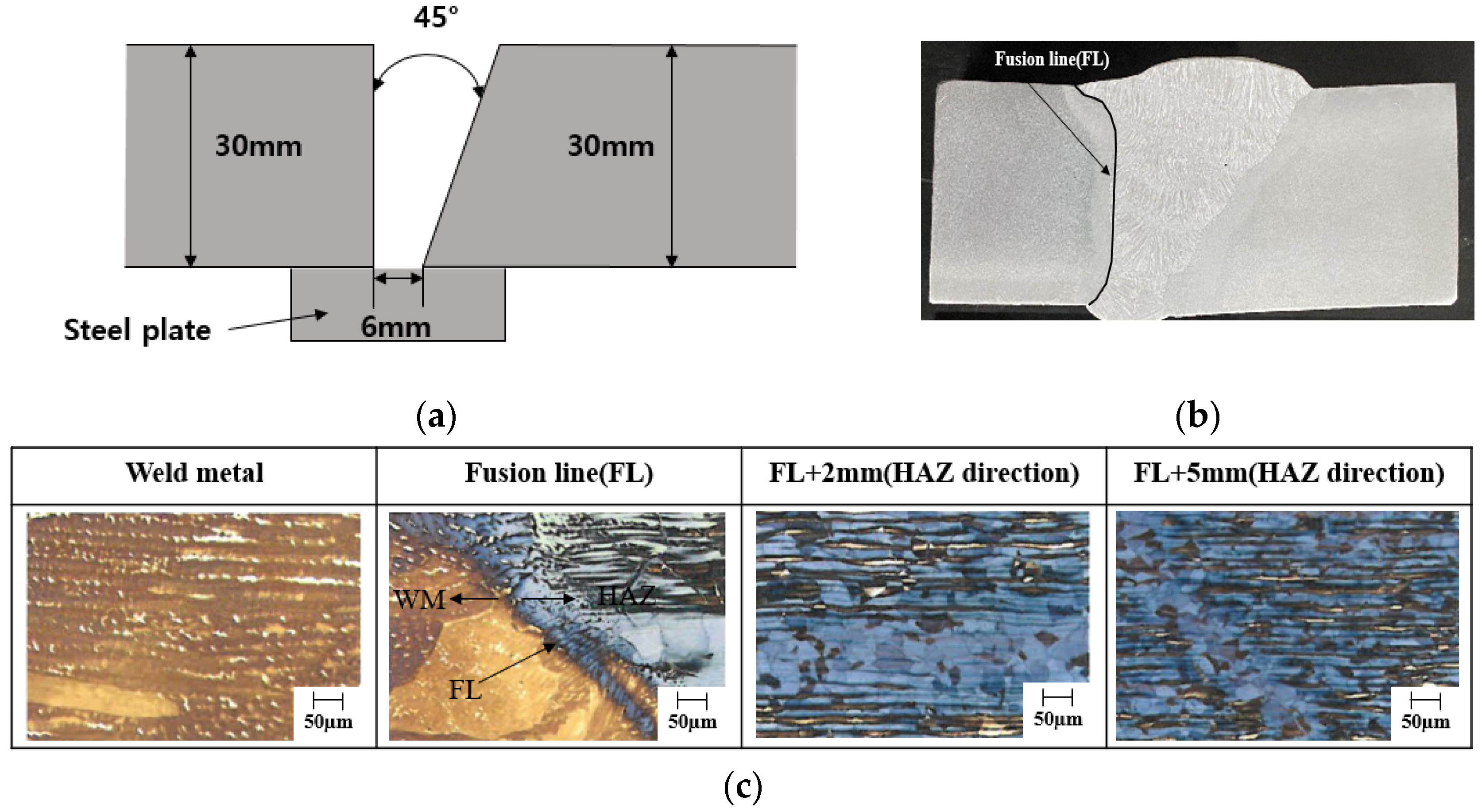
2.1. Specimen Preparation

Currently, with the exception of 9% Ni steel, most cryogenic alloys comprise a face-centered cubic (FCC) crystal structure, as an FCC crystal structure does not normally exhibit a ductile–brittle transition, unlike materials that possess body-centered cubic (BCC) or body-centered tetragonal (BCT) crystal structures. High-manganese austenitic steel containing more than 22% Mn with a face-centered cubic (FCC) crystal structure (such as STS304 steel) was utilized in the experimental examination. Table 1 and Table 2 list the chemical composition and mechanical properties of high-manganese austenitic steel. High-manganese austenitic steel with a thickness of 30 mm, which is the upper limit of production in steel mills, was utilized as the test steel plate. Most steels for cryogenic applications are predominantly comprised of FCC crystal structures to ensure the necessary low-temperature toughness required for cryogenic structures. High-manganese austenitic steel with an FCC crystal structure has been developed for cryogenic LNG tank applications. Charpy and strength impact characteristics satisfy the IGC code standard values [5].

2.2. Experimental Welding Method

The welding test specimens were manufactured for the brittle and ductile fracture characteristics of the weld metal and the heat-affected zone (HAZ) using a wide-plate test via the submerged arc welding (SAW) processes, the typical welding method used for the construction of LNG tanks. Table 3 presents the experimental welding procedure under the SAW conditions. The maximum heat input of each welding method is 3.0 kJ/mm. In addition, a welding consumable with a strength lower than that of the base material was utilized. The tensile strength of the base material is 822 MPa, which is very high, but that of the weld metal is 667–780 MPa, which is considerably lower. Therefore, the test specimen utilized in this study was applied to the undermatched joints. A schematic groove shape (Figure 1a), a macrosection (Figure 1b), and a microstructure (Figure 1c) of the SAW joint are shown in Figure 1. The microstructures show the weld metal and fusion line, fusion + 2 mm, with 5 mm of HAZ direction. The groove angle was 30°, and the root gap was 6 mm. The weld metal, fusion line, and base metal microstructure were fully austenite. Additionally, the number of passes was eight passes in SAW. As for the welding consumable, the developed SAW wire and flux included the same Mn contents as the base metal.

2.3. Test Method

To evaluate the suitability of high-manganese austenitic steel for cryogenic service using a plate thickness of 30 mm, the fracture characteristics of the base material and welded joints were examined. Table 4 presents a list of test items for the bare metal and weld joints. Regarding the brittle fracture characteristics, the toughness was determined using a 3-point bending CTOD test for the base metal and weld joints. A full-thickness notch-penetration wide-plate test was performed on the weld joints to evaluate the ductile fracture characteristics. However, the brittle crack arrestability characteristics were investigated using the duplex ESSO test on the base metal and weld joints. Generally, an austenitic-microstructure material fracture mode exhibits a ductile fracture [3]. The high-manganese austenitic steel utilized in this study has an austenitic structure, and welding consumables have a microstructure similar to the base material; therefore, ductile failure is expected. Consequently, a 3-point bending CTOD test and a wide-tensile test with a central notch were performed to evaluate the unstable ductile fracture phenomenon. The shapes of the test specimens are illustrated in Figure 2.

3. Test Results and Discussion

To apply high-manganese austenitic steel to onshore and offshore LNG storage tanks, the suitability of its use in cryogenic environments must be secured. In addition to basic material properties such as tensile strength and impact values in a cryogenic environment, the verification of fracture safety is of the greatest importance for the application of high-manganese austenitic steel in structures. Because it is utilized in a cryogenic environment, it is necessary to investigate the safety of brittle fractures.

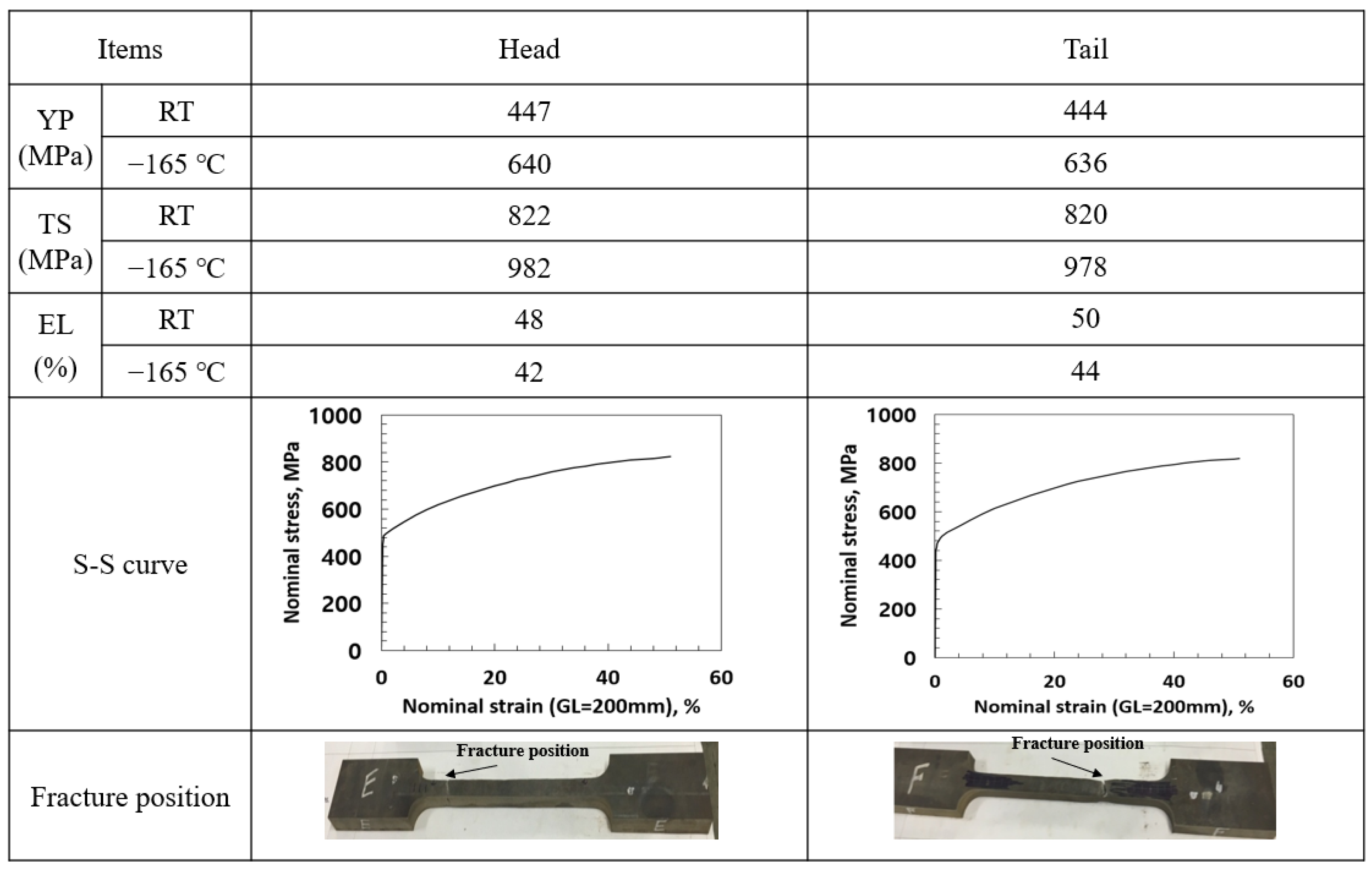
3.1. Suitability Test Results of Base Metal as Cryogenic Steel

The tensile test was performed at 20 °C (room temperature) and −165 °C (cryogenic temperature) with a full-thickness steel plate in the head and tail of the base metal using 1000 kN capacity UTM. In general, the material properties were evaluated using the vulnerable part of the steel plate, such as the head and tail, that tend to be weaker than the material properties at the middle part. The tensile test was performed with a flat tensile test specimen according to ASTM E8/E8M [14]. The gauge and parallel lengths were 200 mm and 220 mm, respectively, and the thickness and width were 30 mm and 25 mm, respectively. The yield strength was 440 MPa with 0.2% offset stress, and the tensile strength was over 820 MPa for both specimens at room temperature. In addition, the strength increases at cryogenic temperatures, such as 640 MPa as yield strength and 982 MPa as tensile strength. It is well known that yield strength and tensile strength increase at low temperatures. Because this experiment was carried out in a cryogenic environment, the increase in strength was more evident. It was also confirmed that the increase in yield strength was larger than the increase in tensile strength. Figure 3 illustrates the tensile test results using the S–S curve and fracture surface at both room and cryogenic temperatures.
Figure 4 illustrates the results of the absorbed energy in the Charpy impact test at −196 °C on the base metal and the strain-aged condition with middle and quarter thicknesses. The Charpy impact test was performed according to ASTM E23 [15]. Even with the application of the 5% strain-aging material (after 5% pre-strain, using the aging treatment at 250 °C for 1 h), the absorbed energy was approximately 100 J or more, which was approximately the same as that of the base metal. The center-position absorbed energy was slightly decreased compared with the quarter position. However, all the absorbed energy in each position satisfies the rule requirement (the ICG code), and the fracture surface indicates 100% ductile fracture while exhibiting excellent fracture toughness properties.

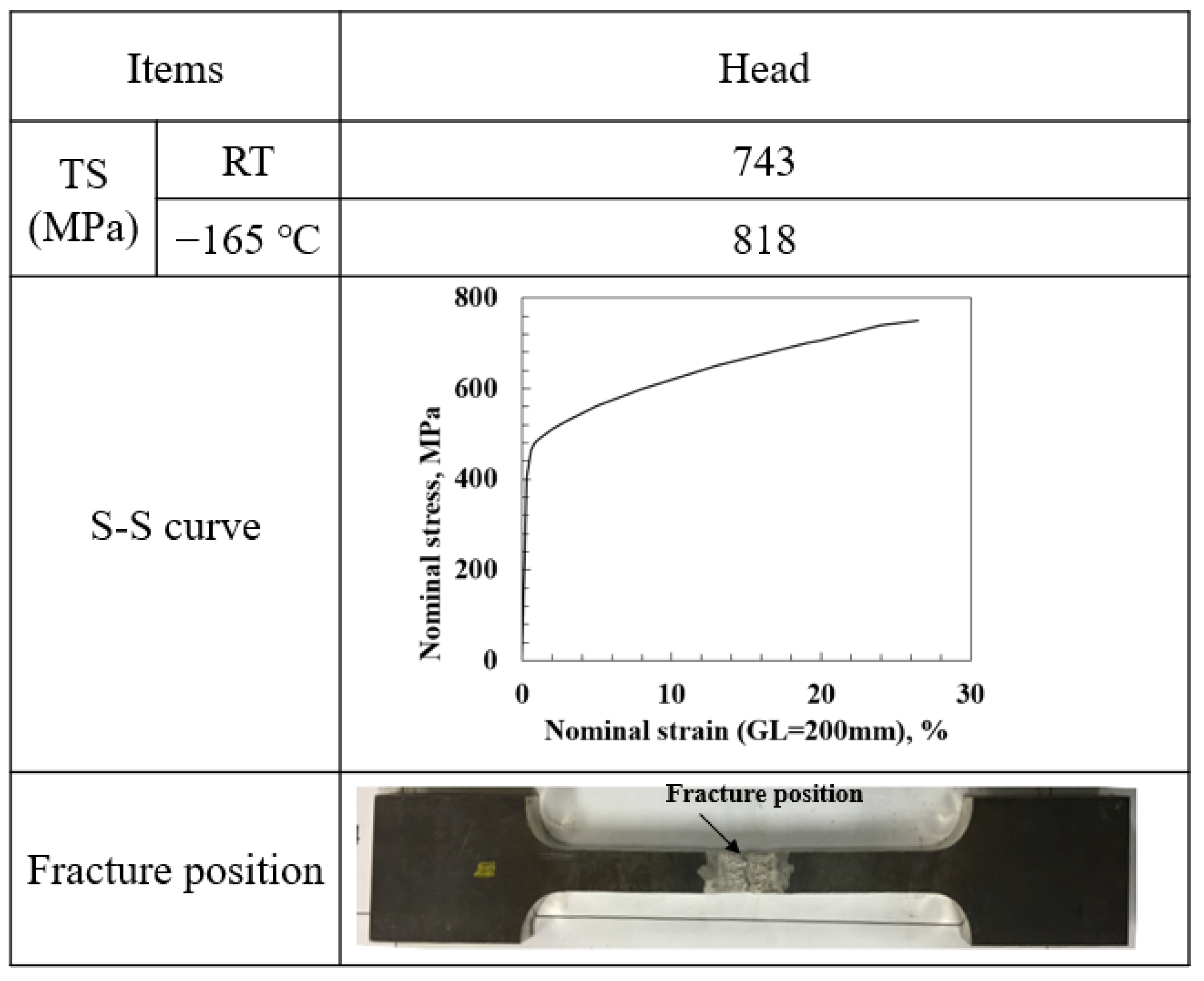
3.2. Suitability Test Results of Weld Joints as Cryogenic Steel

Figure 5 illustrates the results of the tensile test of the weld joint that has full thickness at both room temperature and cryogenic temperature. The gauge and parallel lengths were 200 mm and 220 mm, respectively. The thickness and width were 30 mm and 25 mm, respectively. Tensile strength was approximately 743 MPa at room temperature. This indicates a lower value compared with the base metal because, among commercial welding consumables, it was difficult to determine a high-strength welding consumable equal to the strength of the base material. In addition, the tensile strength increased to about 818 MPa, comparable to the reaction of the base material at cryogenic temperatures. Therefore, the weld joint becomes an undermatched joint, and the fracture position corresponds to the weld metal’s center.
Figure 6 illustrates the results of the absorbed energy using the Charpy impact test at −196 °C on the weld joint using the weld metal (WM), fusion line (FL), fusion line + 2 mm (FL + 2), fusion line + 5 mm (FL + 5), and fusion line + 20 mm (FL + 20). The Charpy impact test was performed according to ASTM E23 [15]. The FL + 2 position indicates the lowest toughness value, and the WM position is approximately 90 J. In general, the results showed low absorbed energy near FL. In the case of multi-pass welding used in this study, the HAZ (heat affected zone) area indicates the embrittlement zone according to reheating. The results of this study also showed low absorbed energy in the HAZ position. The absorbed energy in each position satisfies the rule requirement (the ICG code), and the fracture surface indicates 100% ductile fracture while exhibiting excellent fracture toughness properties.

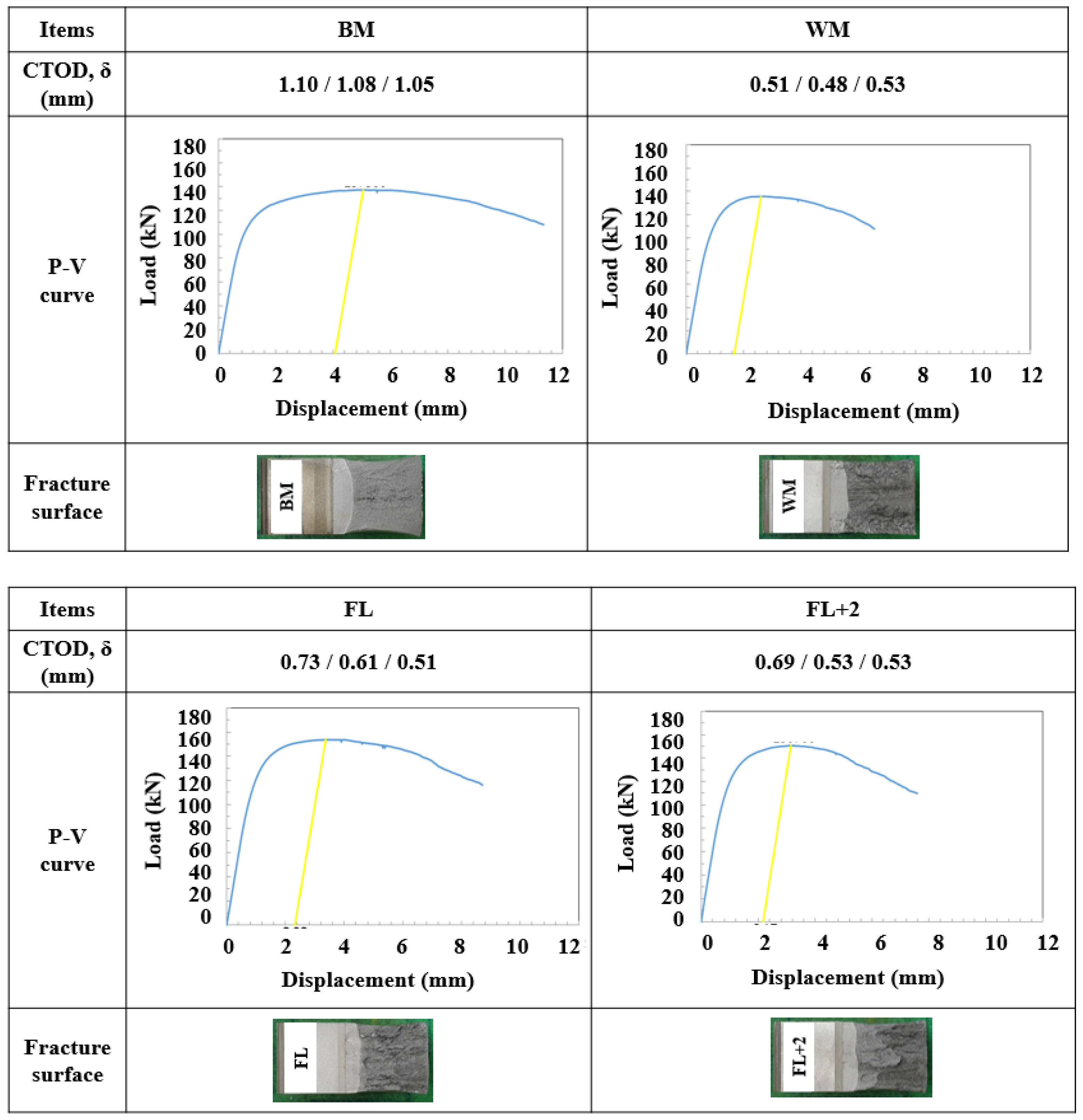
3.3. Brittle Fracture Initiation Behavior Test Results

The results of the brittle fracture toughness test (CTOD: crack-tip opening displacement) at −165 °C using the base metal and weld joints by ISO 12135 and 15653 [16,17,18,19] are illustrated in Figure 7. In P-V curve the yellow line shows the maximum load and displacement. In the base metal, brittle fracture, such as a P-V curve or a fractured surface, did not occur, as illustrated in Figure 7. In addition, a brittle fracture did not occur in the weld metal, which is a typical characteristic of austenitic microstructure steel. Regarding impact toughness, the lowest toughness was evaluated at the FL + 2 mm position, and the FL + 2 mm specimen exhibited the lowest fracture toughness in the CTOD experiment. However, all the specimens exhibited extremely excellent brittle fracture resistance. In the case of carbon steel, it generally displays brittle fracture at low temperatures and has a very low CTOD value at cryogenic temperatures such as −165 °C. However, high-manganese austenitic steel with an austenitic matrix (used in this study) showed stable growth of ductile cracks without brittle fracture even at cryogenic temperatures, similar to the behavior of stainless steel. This is a typical austenitic structure behavior. Therefore, from the CTOD test results, it was determined that there is little possibility of a brittle fracture in the base metal and weld joints of high-manganese austenitic steel. As illustrated in the P-V curve of the CTOD experiment, a brittle fracture did not occur even at cryogenic temperatures, and ductile cracks were stably grown.

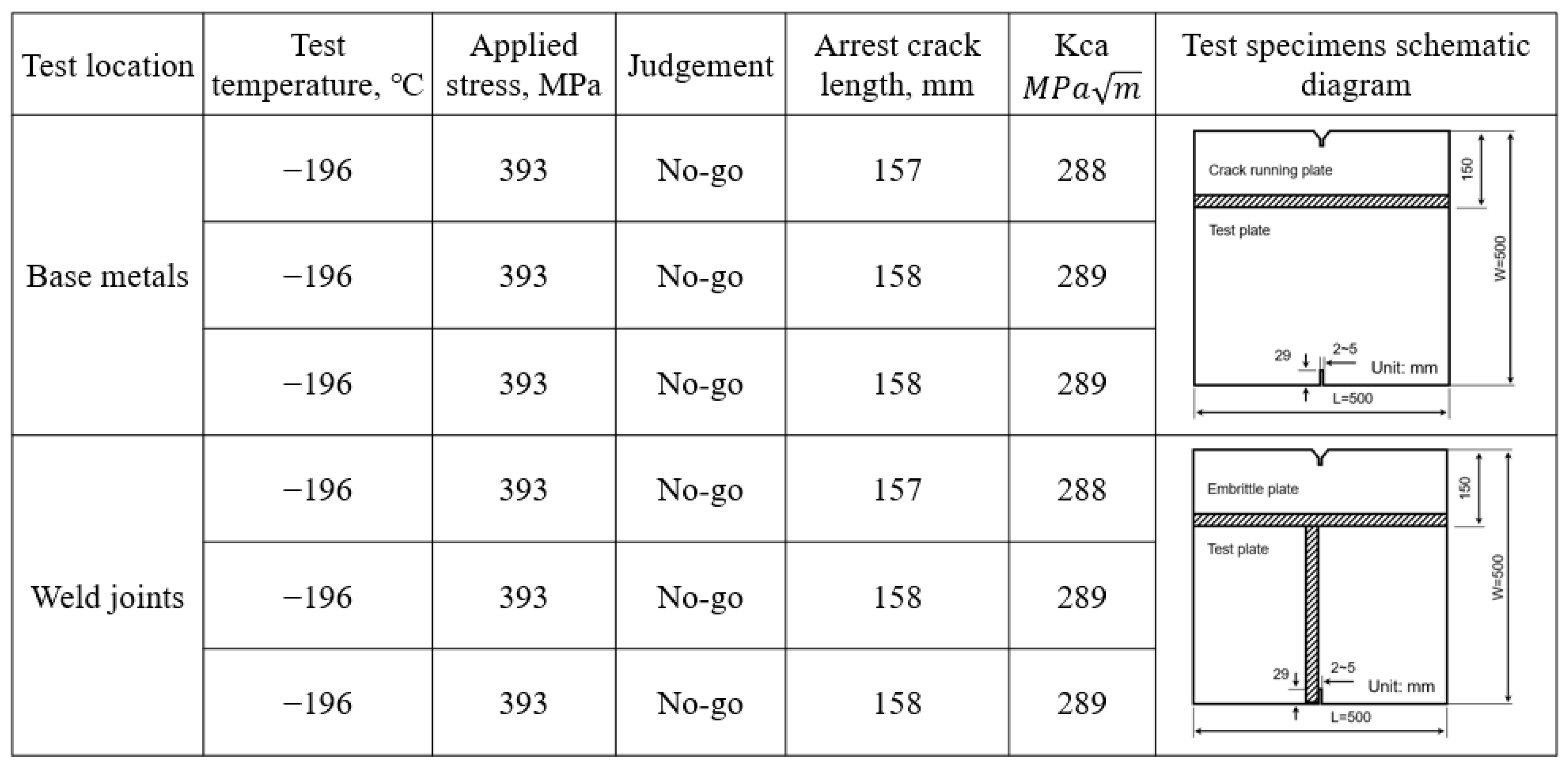
3.4. Brittle Crack Propagation Arrest Test Results

The brittle crack propagation arrest test was performed on the base metal and weld joints using the duplex ESSO test to investigate crack arrestability in both specimens. The duplex ESSO test specimens and test conditions are illustrated in Figure 8. The test temperature was −196 °C for both specimens. The size of the embrittled plate was 500 L × 150 W, and the test plate was 500 L × 350 W. The embrittled zone was created using a running plate to evaluate the brittle crack arrestability of high-manganese austenitic steel. Because brittle cracks should easily propagate using the running plate, a yield strength of 460 MPa-grade steel plate was applied. The running and test plates were welded to the K-groove. The applied stress was 393 MPa as two-thirds of the yield stress of high-manganese austenitic steel, which is significantly higher than the design stress. The base material exhibited a complete ductile fracture in the test plate, and no brittle fracture occurred. The brittle crack propagated in the running plate and then immediately arrested in the test plate. The duplex ESSO test was performed three times under similar test conditions, and similar results were obtained. The brittle crack propagated along the 150 mm embrittled zone, and the crack was arrested in the test specimen after 7–8 mm of propagation. The duplex ESSO test is an experiment used to confirm the brittle crack arrestability of the specimen. As shown in the test result, the brittle crack arrested immediately after propagation, indicating that the brittle crack arrestability of this specimen is excellent.
A similar duplex ESSO test of the base material was performed in the weld joint to determine the brittle fracture toughness. The weld joints were made with a K-groove using the flux-cored arc welding (FCAW) process. It was welded using a welding consumable designed exclusively for high-manganese austenitic steel, and it was welded under the conditions of current 180 A, voltage 26 V, and speed 20 cm/min, with the heat input of approximately 14 kJ/cm. The specimens received 13 passes in the FCAW joints. The brittle crack propagated along the running plate, and the crack was arrested when it met the test welding consumable. The brittle crack propagated approximately 7–8 mm in the welding consumable and was arrested immediately after propagation. As illustrated in Figure 8, the brittle cracks that propagated through the embrittlement plate in any of the test specimens were arrested immediately after entering the test plate. From the duplex ESSO test results, it was determined that high-manganese austenitic steel and welding consumables have little possibility of brittle fracture. The applied stress was 393 MPa, which is significantly higher than the design stress. The driving force of the crack propagation was expressed by the K-value that was approximately 288 MPa√m. Therefore, it is considered that both the base metal and the welding consumable have excellent brittle crack arrestability. However, in the case of high-manganese austenitic steel, as illustrated in the CTOD test results in Figure 7, a brittle fracture does not even occur in a cryogenic environment; therefore, it was determined that brittle fracture safety was good.

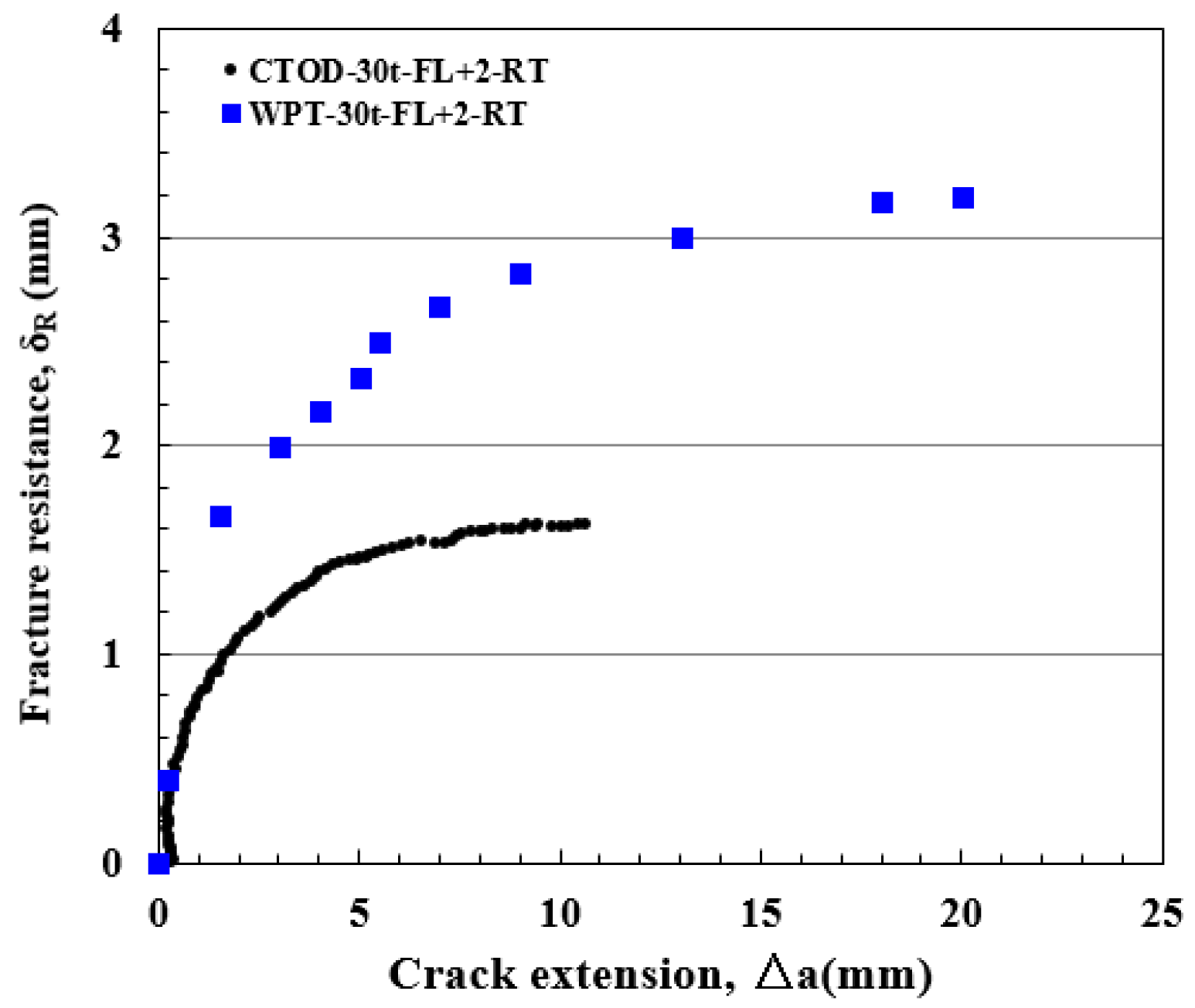
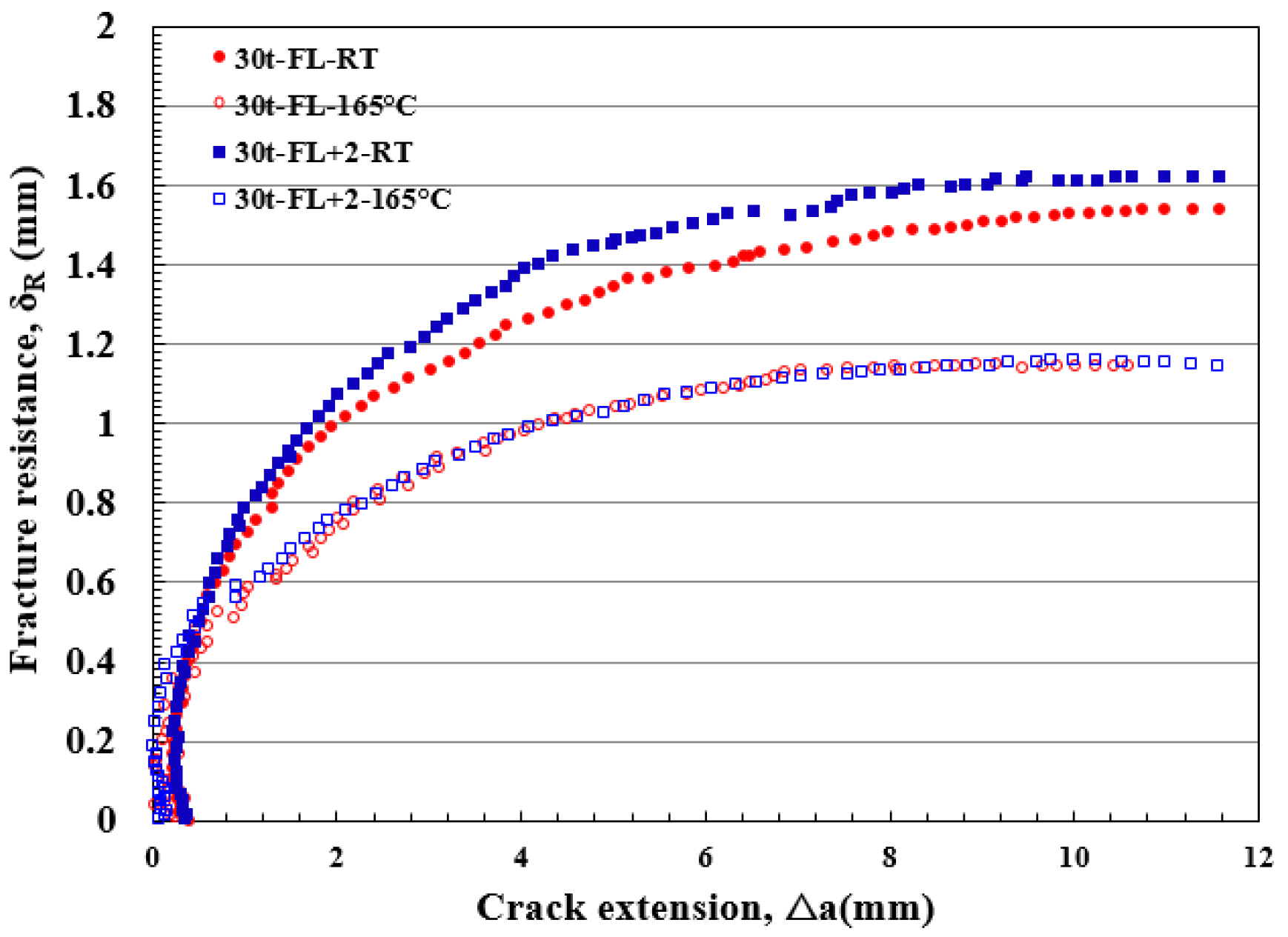
3.5. Unstable Ductile Fracture Test Results

The high-manganese austenitic steel exhibited a negligible possibility of brittle fracture at cryogenic temperatures; therefore, it was necessary to evaluate the possibility of unstable ductile fracture. The ductile fracture resistance of the SAW joints was determined by the three-point bending CTOD and wide-plate tests using fusion line (FL), fusion line + 2 mm (FL + 2), and the weld metal notch was determined using the CTOD–R curve (δR), as illustrated in Figure 2. The CTOD test specimen used a wider width of 4 B (B: specimen plate thickness) compared with the usual 2 B specimen in order to investigate the relationship between the ductile crack length and the resistance value over a wide area. The three-point bending CTOD test was performed at room temperature and at −165 °C. In both cases, partial unloading was repeated during the loading process, and the crack length was determined using Equation (1), according to ASTM E813-89 [20] from the unloading compliance method.
a n W = 0.999748 3.9504 U x + 2.9821 U x 2 3.21408 U x 3 + 51.5156 U x 4 113.031 U x 5 U x = 1 / ( 4 B W E V P S ) 1 / 2
where W, B, and S are the specimen geometric shapes, E is the Young’s modulus, V is the clip gauge displacement, and P is the load.
However, the calculation of the δR value was based on the Wells equation given by Equation (2). This is for comparison with the conventional results [6], and because the δR value is extremely large, it can be considered that the result is approximately similar to the evaluation by the BS5762 formula, which is usually performed.
δ R = 0.45 ( W a n ) ( 0.45 W + 0.55 a n + Z ) × [ V γ σ y W ( 1 υ 2 ) E ]
where σ y : 0.2% the offset yield stress (0.2%), ν: Poisson’s ratio,
γ = 3.3956 X + 1.9282 X 2 7.10161 X 3 + 4.0484 X 4 ,   ( X = a n / W )
In the testing, the measurement of the length of the ductile crack was very difficult, so the ductile crack length was determined using the unloading compliance method [21,22]. The fracture resistance value, δR, was calculated from the clip gauge displacement at each load level. Figure 9 illustrates an example of unloading compliance in a wide-plate test using the FL + 2 specimen. The wide-plate test was carried out with 10,000 kN UTM. The ductile crack extension length was measured in all thickness directions using the three-point bending test. Under unloading conditions on the surface, the visual method [22,23] was used to estimate the crack length form and compliance [21,24,25,26,27]. This method directly measured the crack length in the complete unloading condition using beach marks on the crack surface. The fracture resistance value (δR) was calculated from the clip-gauge displacement at each load level. In order to calculate the fracture resistance (δR), it is important to accurately measure the crack propagation length. Therefore, the fracture resistance was calculated by estimating the crack length with relative accuracy based on the directly measured crack length and the beach marks on the fracture surface after the experiment.
Figure 10 illustrates the δR curve (relationship between δR and crack extension) obtained in the wide-plate and three-point bending CTOD tests with FL + 2 specimens at room temperature. The δR curve had a steep slope in the initial crack extension stage, gradually increased until just after a 30 mm crack extension, and finally converged. The δR value was maximized after an approximately 30 mm crack extension measuring about 3.2 mm in the wide-plate test and 1.6 mm in the CTOD test. The two testing methods show a slight difference in test results using similar notch positions. In the three-point bending CTOD test, δR exhibits a low value when compared with the wide-plate test. Comparing the results of the CTOD and the wide-plate tests, the wide-plate test exhibits a slightly larger resistance value. Both test methods show different loading modes. Regarding the influence of the loading mode, the δR value using the wide-plate test showed a slightly larger value, but it was comparable to the results obtained using the conventional uniform base material [28].
The results of the three-point bending CTOD test indicated that the ductile fracture resistance value differed depending on the test temperature, and the δR value at −165 °C was smaller than that at room temperature, which was approximately 71% in FL + 2 and 74% in FL specimens, as indicated in Figure 11. The effect of the test method on the δR value was evaluated between the wide-plate and three-point bending tests. The wide-plate test indicated a 1.5 times larger value of δR at a similar test temperature. It is judged that the bending load is more fatal to the failure mode; therefore, the structural safety should be evaluated using the bending load. In addition, the high-manganese austenitic base metal and weld joints have excellent fracture safety.

4. Conclusions

In this study, the brittle fracture characteristics of a high-manganese austenitic steel plate for an applicable LNG storage tank were investigated. The material properties of the new cryogenic steel were evaluated using the base material and weld joints based on the IGC/IGF code to examine its suitability as cryogenic steel. In particular, the fracture toughness in the weld joints, which determines the risk of unstable fracture, was investigated using a large-scale wide-plate test and a three-point bending test under cryogenic conditions. The results are as follows.
(1) The high-manganese austenitic steel base metal and the weld joints showed excellent material properties as new cryogenic steel, and brittle fracture resistance had sufficient safety as a material for cryogenic steel. Thus, it satisfied the IGC/IGF code for each requirement.
(2) In the case of high-manganese austenitic steel, the three-point bending test results showed that there is little possibility of brittle fracture. No brittle fracture occurred even after the maximum load, and the fracture surface exhibited only ductile fracture at cryogenic temperatures.
(3) Furthermore, brittle crack arrestability was evaluated using duplex ESSO testing, and it indicated excellent performance in brittle crack arrest in both the base metal and weld joints.
(4) Owing to the wide-plate and three-point bending test results, the possibility of unstable ductile failure on the influence of the load mode was determined to be more conservative when related to the bending load than the tensile load; however, it was judged that there was little possibility of unstable failure owing to the material’s excellent resistance to unstable ductile failure.
Based on these results, it is determined that high-manganese austenitic steel has excellent unstable fracture characteristics and good material performance as cryogenic steel; therefore, it can be applied to LNG storage and fuel tanks.

Author Contributions

G.A. and J.P. jointly conceived and designed the experiment, performed the experiment and conducted data analysis. G.A., H.P. and I.H. analyzed the data and plotted the figures, wrote this paper. J.P. provided scientific guidance. All authors have read and agreed to the published version of the manuscript.

Funding

This study was funded by Chosun University grant number 2021. This research was supported by Basic Science Research Program through the Na-tional Research Foundation of Korea (NRF) funded by the Ministry of Education (NRF-2017R1D1A1B04029150).

Data Availability Statement

The data are not publicly available. The data presented in this study are available on request from the corresponding author.

Conflicts of Interest

The authors declare no conflict of interest.

References

  1. Moon, D.; Kim, D.; Lee, J.; Kim, M. Estimation of Constraint Factor on the Relationship between J integral and CTOD for Offshore Structural Steel Weldments. J. Offshore Mech. Arct. Eng. 2015, 137, 064001. [Google Scholar] [CrossRef]
  2. Kang, S.; Kim, M.; Kim, Y.; Shin, Y.; Lee, H. A Study on the Fracture Toughness Characteristics of FCAW Weldment of Steel for Offshore Structures. J. Korea Weld. Join. Soc. 2004, 22, 57–63. [Google Scholar]
  3. Machida, S.; Deguchi, A.; Kagawa, H. Brittle fracture characteristics of heavy gauge 9% Ni steel plate for large scale LNG strage tank. J. High Press. Inst. Jpn. 1993, 31, 31–38. [Google Scholar]
  4. Niu, W.; Lina, J.; Ju, Y.; Fu, Y. The daily evaporation rate test and conversion method for a new independent type B LNG mock-up tank. Cryogenics 2020, 111, 103168. [Google Scholar] [CrossRef]
  5. Han, I.; Lee, B. Microstructure and Mechanical Properties of Cryogenic High-Manganese Steel Weld Metal. Int. J. Offshore Polar Eng. 2017, 27, 260–265. [Google Scholar] [CrossRef]
  6. IGC Code. Code for the Construction and Equipment of Ships Carrying Liquefied Gases in Bulk; International Maritime Organization: London, UK, 2020. [Google Scholar]
  7. IGF Code. International Code of Safety for Ships Using Gases or Other Low-Flashpoint Fuels; International Maritime Organization: London, UK, 2020. [Google Scholar]
  8. Interim Guidelines on the Application of High Manganese Austenitic Steel for Cryogenic Service; International Maritime Organization: London, UK, 2018.
  9. Machida, S.; Ishikura, N.; Kubo, N.; Katayama, N.; Muramoto, S.; Hagiwara, Y.; Arimochi, A. Fracture Characteristics of Heavy Thickness 9% Ni Steel Plate and its Applicability to Large Scale LNG Storage Tanks (2nd Report, High Toughness 50–55mm Thick 9% Ni Steel Plate). J. High Press. Inst. Jpn. 1993, 31, 19–33. [Google Scholar]
  10. Machida, S.; Ishikura, N.; Kubo, N.; Katayama, N.; Muramoto, S.; Hagiwara, Y.; Arimochi, A. Brittle fracture characteristics of heavy thickness 9% Ni steel plate and its applicability to large scale LNG storage tanks. J. High Press. Inst. Jpn. 1991, 29, 25–39. [Google Scholar]
  11. Watanabe, I.; Suzuki, M.; Matsuda, Y.; Yamagata, S.; Yajima, H. The crack-arrest properties of 9% Ni steel and its weldment (1st report). Bull. Jpn. Soc. Nav. Arch. Ocean. Eng. 1984, 155, 389–400. [Google Scholar] [CrossRef]
  12. Watanabe, I.; Suzuki, M.; Matsuda, Y.; Yamagata, S.; Yajima, H. The crack-arrest properties of 9% Ni steel and its weldment (2nd report). Bull. Jpn. Soc. Nav. Arch Ocean. Eng. 1984, 155, 401–407. [Google Scholar]
  13. An, G.; Hong, S.; Park, J.; Ro, C.; Han, I. Identification of Correlation Between Fracture Toughness Parameters of Cryogenic Steel Weld Joints. J. Weld. Join. 2017, 35, 82–87. [Google Scholar] [CrossRef] [Green Version]
  14. American Society for Testing and Materials. Standard Test Methods for Tension Testing of Metallic Materials; American Society for Testing and Materials: West Conshohocken, PA, USA, 2021. [Google Scholar]
  15. American Society for Testing and Materials E23. Standard Test Methods for Notched Bar Impact Testing of Metallic Materials; American Society for Testing and Materials: West Conshohocken, PA, USA, 2021. [Google Scholar]
  16. International Standard. Metallic Materials-Unified Method of Test for the Determination of Quasistatic Fracture Toughness; ISO 12135; International Organization for Standardization: Geneva, Switzerland, 2018. [Google Scholar]
  17. International Standard. Metallic Materials-Unified Method of Test for the Determination of Quasistatic Fracture Toughness of Welds; ISO 15653; International Organization for Standardization: Geneva, Switzerland, 2018. [Google Scholar]
  18. British Standard Institute. Fracture Mechanics Toughness Tests-Part 1:Method for Determination of KIC, Critical CTOD and Critical J Values of Metallic Materials; BS7448; British Standard Institute: London, UK, 1991. [Google Scholar]
  19. British Standard Institute. Fracture Mechanics Toughness Tests-Part 2:Method for Determination of KIC, Critical CTOD and Critical J Values of Welds in Metallic Materials; BS7448; British Standard Institute: London, UK, 1997. [Google Scholar]
  20. American Society for Testing and Materials E813-89. Test Method for JIC, A Measure of Fracture Toughness; American Society for Testing and Materials: West Conshohocken, PA, USA, 1997. [Google Scholar]
  21. Tada, H.; Paris, P.; Irwin, G. The stress analysis of cracks hand book, Del Research corporation. Louis Mo. 1973, 29, 367–380. [Google Scholar]
  22. Tsukamoto, M.; Kwaguchi, Y.; Machida, S. Ductile instability of long arrested crack under R-curve concept. Bull. Jpn. Soc. Nav. Arch Ocean. Eng. 1987, 161, 337–342. [Google Scholar] [CrossRef]
  23. Park, S.; Lee, C.; Choi, S.; Kim, J.; Bang, C.; Lee, J. Polymeric foams for cryogenic temperature application: Temperature range for non-recovery and brittle-fracture of microstructure. Compos. Struct. 2016, 136, 258–269. [Google Scholar] [CrossRef]
  24. Nakanishi, D.; Kawabata, T.; Aihara, S. Effect of dispersed retained γ-Fe on brittle crack arrest toughness in 9% Ni steel in cryogenic temperatures. Mater. Sci. Eng. A 2018, 723, 238–246. [Google Scholar] [CrossRef]
  25. Weiss, K.; Kraskowski, A.; Koukolíková, M.; Podaný, P. Micromechanics driven design of ferritic–austenitic duplex stainless steel microstructures for improved cleavage fracture toughness. Eng. Fract. Mech. 2021, 253, 107878. [Google Scholar]
  26. Shibanuma, K.; Yanagimoto, F.; Suzuki, K.; Aihara, S. Brittle crack propagation/arrest behavior in steel plate-Part III: Discussions on arrest design. Eng. Fract. Mech. 2018, 190, 104–119. [Google Scholar] [CrossRef]
  27. Taylor, J.; Mehmanparast, A.; Kulka, R.; Moore, P. Correlation between steel initiation toughness and arrest toughness determined from small-scale mechanical testing. Procedia Struct. Integr. 2019, 17, 472–478. [Google Scholar] [CrossRef]
  28. Garwood, S.J. Effect of specimens germetry on crack growth resistance, Fracture Mechanics. Am. Soc. Test. Mater. 1979, 677, 511–532. [Google Scholar]
Figure 1. Macrosection and microstructure of 30 mm thick steel plate. (a) Schematic of the groove shape. (b) Macrosection of SAW joint. (c) Microstructure of SAW joint.
Metals 11 02047 g001
Figure 2. Test specimens to evaluate the suitability of high-manganese austenitic steel. (a) CTOD specimen geometry of the weld joint. (b) Duplex ESSO test specimen geometry using the base metal. (c) Duplex ESSO test specimen geometry using the base metal. (d) Wide-plate test specimen geometry of the weld joint using the base metal.
Metals 11 02047 g002
Figure 3. Tensile test results of base metal at the head and tail of the steel plate.
Metals 11 02047 g003
Figure 4. Charpy impact test at −196 °C using base metal and strain-aged conditions.
Metals 11 02047 g004
Figure 5. Tensile test results using the SA weld joint.
Metals 11 02047 g005
Figure 6. Charpy impact test at −196 °C with weld joints.
Metals 11 02047 g006
Figure 7. CTOD test results at −165 °C using the base metal and weld joints. (In P-V curve, the yellow line shows the maximum load and displacement; the blue line shows the P-V curve.)
Metals 11 02047 g007
Figure 8. Duplex ESSO test results for the base metal and weld joints at −196 °C.
Metals 11 02047 g008
Figure 9. Example of wide-plate test R-curve recorded at room temperature.
Metals 11 02047 g009
Figure 10. Compared results using the three-point bending test and the wide-plate test on fracture resistance.
Metals 11 02047 g010
Figure 11. Fracture resistance of FL and FL + 2 in three-point bending test at RT and −165 °C.
Metals 11 02047 g011
Table 1. Chemical composition of the base metal.
MaterialsChemical Composition (Mass, %)
CSiMnCuPS
High-manganese austenitic steel0.35~0.550.10~0.5022.5~25.500.30~0.70Max. 0.03Max. 0.01
Table 2. Mechanical properties of the base metal using the plate-bar type tensile specimen.
MaterialsThickness (mm)Yield Strength (MPa)Tensile Strength (MPa)Elongation (%)Charpy Impact energy (J, −196 °C)
H-Mn30 mm44482256105 (transverse)
Table 3. Submerged arc welding conditions.
Welding ProcessThickness (mm)Current (A)Voltage (V)Speed (cm/min)Heat Input (kJ/mm)
SAW3058028323.0
Table 4. Test items for base metal and weld joints with high-Mn steel.
MaterialsTest Items
Base metal
Macro- and microstructures
Tensile test
Charpy impact test
CTOD test
Duplex ESSO test
Weld joints
Macro- and microstructures
Tensile test
Charpy impact test
CTOD test
Duplex ESSO test
δ-R curve 3-point bend test
Wide plate ductile fracture test
Publisher’s Note: MDPI stays neutral with regard to jurisdictional claims in published maps and institutional affiliations.

