Abstract
In this article, a digitized stress function-based feed rate scheduling algorithm is formulated for the prevention of tool breakage while having an optimum material removal rate in mesoscale rough milling of hardened steel. Instead of setting limits to the cutting forces and material removal rates, the presented method regulates the tool’s stresses. A 3D coupled Eulerian-Lagrangian finite element method (FEM) model is used to simulate a 3D chip flow-based stress according to the mesoscale tool’s rotation during cutting of hardened steel. Maximum uncut chip thickness and tool engaging angle of the uncut chip is identified as the fundamental driving factors of tool breakage in down milling configuration. Furthermore, a multiple linear regression model is formed to digitize the stress with two major factors for digitized feed scheduling. The optimum feed rates for each segment along the tool path can be obtained through finite element models and a multiple linear regression model. The feed rate scheduling method is validated through cutting experiments with tool paths of linear and arc segments. In a series of experimental validations, the algorithm demonstrated the capability of reducing the machining time while eliminating cutting tool breakages.
1. Introduction
In the rough milling processes, higher feed rates ensure faster material removal and higher productivity. However, high feed rates could lead to tool breakages, especially when cutting hard metals with miniature tools. There are generally two types of feeding motion control in computer-controlled cutting operations: linear interpolation and arc interpolation. The cutting tool experiences varying cutter-workpiece engagements along the tool path even with constant cutting depths. Therefore, a feed rate scheduling method is required to find optimum feed rates for each segment of the tool path while preventing tool breakages in milling processes of hardened metals with HRC over 40.
Many published articles discuss feed rate scheduling with constraints of force and material removal rate. Wang [1] developed a solid modeling system for optimization of the end milling process based on the regulation of material removal rates (MRR). Karunakaran and Shringi [2] presented an offline adaptive control method for feed rate optimization for the end milling process. The geometry of the undeformed chip was investigated for the prediction of the cutting forces. The feed rate was adjusted based on a cutting force limit. Li et al. [3] introduced an offline feed rate scheduling system based on integration of MRR regulation and CAD/CAM for three-axis end milling. Ridwan et al. [4] proposed a feed rate optimization method for efficient machining. Fuzzy adaptive control was used to achieve a constant cutting force by adapting feed rate automatically according to the cutting conditions. Spence and Altintas [5] presented a Constructive Solid Geometry (CSG) based process simulation system for 2.5 axis milling. The feed rate was adjusted according to force, torque, and part dimensional error constraints. Lee and Cho [6] proposed a feed rate scheduling method for rough milling processes based on a reference cutting force model. The reference cutting force was calculated through finite element method (FEM). It functioned as a cutting force threshold in the milling processes to avoid tool breakages. Similar methodologies were implemented for ball-end milling [7] and studies involved modeling cutting forces [8,9]. Mamedov and Lazoglu [10] introduced a feed rate scheduling technique for micro ball-end milling process. The cutting force model to predict cutting force was based on fitted cutting coefficients, which assumed a linear correlation between feed-per-tooth and cutting force. The feed rate planning method was borrowed from the study of Erdim and Lazoglu [11], which employed a predefined threshold value for resultant cutting force without a detailed explanation. Özel and Liu [12] proposed a micro-end milling process planning technique based on cutting mechanics. An analytical model was formulated, emphasizing achieving good surface quality of finishing cut. For rough milling, a predefined cutting force threshold was used to avoid premature tool failure. The determination of the threshold cutting force that causes tool failure was not explained in detail. Liang et al. [13] introduced a mechanics-based cutting force and torque regulation method for feed rate scheduling of multi-axis plunge milling. Ferry and Altintas [14] introduced a feed rate optimization method for 5-axis flank milling processes. The cutting conditions were planned considering the constraints of the tool shank bending stress, tool deflection, maximum chip load, and the torque limit of the machine. However, tool stress and breakage close to tool tips were not discussed in the study. Li et al. [15] proposed a feed rate optimization method based on cutting force prediction for variant surface milling process. Fussell et al. [16] developed a feed rate process planner for complex sculptured end milling based on discrete mechanistic and geometric end milling models. The cutting force and the feed-per-tooth at the divided microsegments were constrained according to tool deflection, surface finish, tool failure and machine power. Similar methods of cutting force regulation were adopted by Guzel and Lazoglu [17] for feed rate scheduling in sculpture surface machining. Erdim et al. [18] introduced feed rate scheduling strategies for free-form surfaces based on cutting force models and regulation of MRR. Zhang et al. [19] integrated geometric and mechanistic models for force prediction and feed rate scheduling in five-axis CNC free-form surface machining. The models were implemented with a threshold of cutting force to obtain optimal feed rates. Tikhon et al. [20] proposed a NURBS interpolator based on the adaptive feed rate control for the constant MRR. The method was accomplished by adjusting feed rate according to the curvature of a surface.
In summary, most existing feed rate scheduling methods for the prevention of tool breakage and chipping were based on the regulation of cutting forces and MRR. However, the cutting forces and MRR do not precisely indicate the stress experienced by the tool. It has been shown that the tensile stress in the cutter is not positively correlated with resultant cutting force in shoulder milling processes [21]. Furthermore, selecting thresholds for cutting force and MRR in the presented methods is not based on the stress value.
In this study, a feed rate scheduling method based on stress regulation is developed for down milling of hardened stainless steel 440C. The geometry of the uncut chip is analyzed in-depth for tool breakage prediction. A multiple linear regression model is devised to estimate the tensile stresses based on the uncut chip geometry, radial cutting depth, and tool path curvature. The planning of feed rates is then achieved through regulating the maximum tensile stress in the cutting tool along the tool path. Validation experiments are conducted with tool paths that involve linear and arc segments with various radii. It is observed that the method is capable of reducing the machining time without causing tool breakages.
2. Evaluation of Maximum Thickness and Engaging Angle of the Uncut Chip for Tool Breakage Prediction
The tool stress is not positively correlated with resultant cutting forces in terms of cutting tool rotation [21]. Since the maximum tensile stress in the tool is reached immediately after the tool engages the workpiece in down milling configuration, there are two factors that have significant impacts on the stress of the tool: maximum uncut chip thickness and tool engaging angle of the uncut chip.
Maximum uncut chip thickness (t_max) refers to the maximum thickness of the uncut chip to be removed by the end mill in radial direction of the tool. The uncut chip engaging angle (α) is the angle between the workpiece surface and the tangential direction of the end mill at the entry point of the tool as shown in Figure 1. These factors two variables change according to the radial cutting depth and curvature of the tool path.
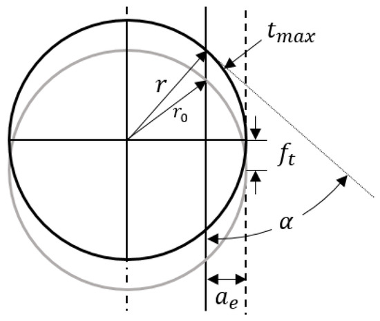
Figure 1.
Maximum thickness and engaging angle of the uncut chip in a linear motion.
The maximum thickness and engaging angle of the uncut chip can be calculated based on the cutting conditions. The trochoidal trajectory of the tool tip is approximated as consecutive circles. With linear tool path, the uncut chip engaging angle α can be shown as:
where is the radius of the end mill and is the radial cutting depth. The maximum uncut chip thickness can be derived as:
where is the feed per tooth.
When the end mill is cutting in an arc interpolation, the maximum thickness and engaging angle of the uncut chip are influenced by the radius of curvature of tool path even though the radial cutting depth is constant. As shown in Figure 2, the entry angle respect to instantaneous feed direction can be shown as:
where is the radius of tool path, which has a positive value when the tool is going in clockwise direction. When the end mill is going counter-clockwise and cutting a concave surface, R is assigned to be negative. The engaging angle of the uncut chip can be expressed as:
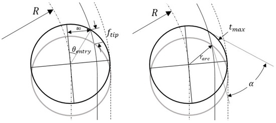
Figure 2.
Down milling with arc interpolation.
The maximum uncut chip thickness in arc interpolation can be shown as:
where is the actual feed per tooth experienced by the tip of the end mill.
3. Prediction of the Maximum Tensile Stress in the Cutting Tool
For a given cutting condition, the maximum tensile stress in the cutting tool can be evaluated based on the previously developed tool stress analysis method [21]. The cutting processes were simulated using a 3D coupled Eulerian-Lagrangian (CEL) FEM model based on Abaqus/Explicit (2018, Dassault Systèmes, Vélizy-Villacoublay, France). The contact forces at the tool-chip interfaces were then transferred to a static FEM model for the analysis of tool stress. Predictions of the FEM models are shown in Figure 3 and Figure 4. The down milling of hardened stainless steel 440C was simulated with 0.3 mm axial cutting depth, 1 mm radial cutting depth, and 0.08 mm feed per tooth under 3000 RPM spindle speed.
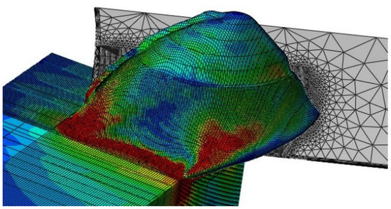
Figure 3.
Cutting process simulated by the 3D coupled Eulerian-Lagrangian (CEL) finite element method (FEM) model.
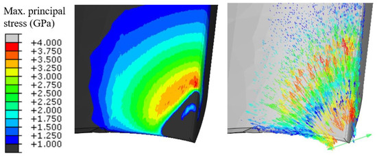
Figure 4.
Predicted maximum principal stress of the end mill and corresponding directions.
A series of simulation was conducted with various cutting conditions. The cutting tool used was MS2MSD0300, a double flute 3 mm solid carbide end mill with sharp corner edges. The geometrical parameters of the cutting tool are shown in Table 1 [22]. The transverse rupture strength (TRS) of the tool was measured to be 4.06 GPa [21]. The workpiece was hardened stainless steel 440C with a yield strength of 1900 MPa and a hardness of 55 HRC [23,24]. The axial cutting depth was fixed as 0.3 mm and the spindle speed was 3000 rpm.

Table 1.
The end mill (MS2MSD0300) geometric information [22].
In down milling configuration, the maximum tensile stress is reached at tool entry. Only a very short period in the beginning of the chip formation process needs to be simulated. Therefore, the computational cost of the stress prediction can be minimized.
The maximum tensile stresses are predicted using the CEL FEM model for the process configuration and the maximum uncut chip thickness, engaging angle of the uncut chip, and corresponding predicted maximum tensile stress in the end mill are shown in Table 2.
Table 2.
List of predicted maximum tensile stress.
The linear regression was conducted with five explanatory variables, the maximum tensile stress in the cutting tool can be expressed empirically as:
with in GPa, in mm, and in rad, the coefficients of the regression model were determined as shown in Table 3 [25].
Table 3.
Coefficients of the multiple linear regression model.
The regression model and the tool stress data predicted by FEM model are plotted in Figure 5 using Matlab (R2019a, MathWorks, Natick, MA, USA). The model’s R-squared value is above 96%, which means the model is accurate. It is found that tool stress under any cutting conditions with 0.3 mm axial depth of cut can be estimated based on the maximum thickness and engaging angle of the uncut chip through a multiple linear regression of the simulation results. Based on the model, maximum tensile stress of the cutting tool under various radial cutting depths and tool paths can be evaluated.
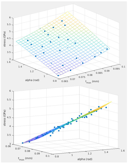
Figure 5.
Tool stress data and multiple linear regression model.
4. Feed Rate Scheduling Based on Digitized Maximum Tensile Stress Function and Experimental Validation
The proposed feed rate scheduling method is formulated through the regulation of maximum tensile stress in the cutting tool rather than regulating cutting forces and MRR. The feed rates were scheduled in order to achieve reduction in machining time and prevent cutting tool breakage based on the threshold of the stress value. In down milling operation of hardened stainless steel 440 C using the specific end mill, at an axial cutting depth of 0.3 mm, the maximum tensile stress in the cutting tool in each segment of the tool path can be digitized as:
where is the consolidated function based on Equation (6) in which and can be calculated using the cutting conditions , , and . The objective of the feed rate scheduling method is to find an optimum value for such that,
where is a scaling factor less than 1, and is the transverse rupture strength of the tool. The optimum feed per tooth can be determined through solving the inverse function using Newton–Raphson method. The feed rate for double-flute end mills can be obtained:
where is the spindle speed. At the transitions between the segments of tool path, the cutting tool experiences varying maximum thickness and engaging angle of the uncut chip. The lower scheduled feed rate of the adjoining tool path segments was used for each transition. The length of the transition at the end of the tool path segments can be derived through calculating the position of the tool when the tool tip reaches the end of the current segment. For linear segments as demonstrated in Figure 6, the transition length can be expressed as:
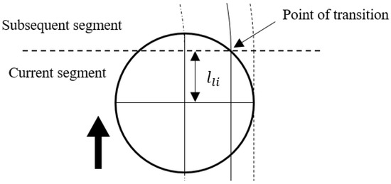
Figure 6.
Length of transition for linear segments.
The transition length at the end of arc interpolation can be expressed as:
When scheduling feed rates at tool center positions are indicated in G-codes, the transition length is considered in G-codes segments. Since the maximum uncut chip location is ahead of the tool center location, feed rate scheduling makes sure that the tool decelerates in advance if the next segment requires a lower feed rate.
4.1. 1st Tool Path with Concave Curvature and Small Radial Cutting Depth
To demonstrate the feed rate scheduling method, validation experiments were conducted using tool paths with various curvatures. The tool paths are composed of line and arc segments with no sharp turns. The first target contour and the corresponding tool path are shown in Figure 7.
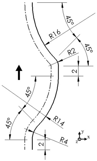
Figure 7.
The 1st target contour (solid line) and corresponding tool path (chain line), dimensions in mm.
The axial cutting depth was 0.3 mm, the spindle speed was 3000 rpm, and the radial cutting depth was 0.3 mm throughout the tool path. The feed rate was set to be 900 mm/min (0.15 mm feed per tooth). According to the regression model, tool breakage was expected while machining the concave surface with the smallest radius of curvature. The predicted maximum tensile stress of the end mill along the tool path is shown in Figure 8.
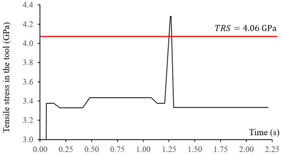
Figure 8.
Predicted tool stress along the 1st tool path with constant feed rate.
The measured resultant cutting force and axial cutting force at a constant feed rate of 900 mm/min are shown in Figure 9. Breakage of the end mill can be easily identified due to significant increases in the cutting forces. Tool breakages happened at the arc interpolation segment with the smallest radius of 0.5 mm, which can also be observed from the machined surface. The broken tool was also inspected as presented in Figure 10. Tool breakages happened on both flutes of the end mill. Through the regression model, tool breakage could be accurately predicted even without conducting the actual FEM simulation.
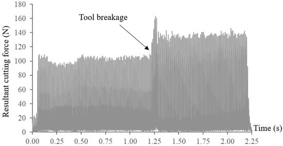
Figure 9.
Resultant cutting force in 1st tool path without feed rate scheduling.
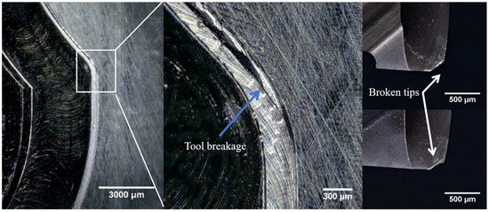
Figure 10.
Machined surface and the broken tool.
In order to prevent tool breakages in the milling process, the scheduling of feed rates was conducted based on Equations (1)–(11). By setting the scaling factor to 0.9, which regulates the maximum tensile stress of the cutting tool at 90% of its transverse rupture strength, the scheduled feed rates can be obtained for each segment of the tool path. At the transition regions, the relatively conservative feed rates were used. The stresses in the tool were regulated through the feed rate scheduling process. The corresponding G-codes for the tool path with highlighted scheduled feed rates are shown in Table 4:
Table 4.
G-codes with feed rate scheduling for the 1st tool path.
Decreases of measured cutting forces were observed when the feed rate was scheduled at the critical tool path segment as shown in Figure 11. With the scheduled feed rates, tool breakages were eliminated with even shorter machining time. The machined surface and the condition of the end mill after machining are presented in Figure 12. Tool wear was observed at the tips of the end mill.
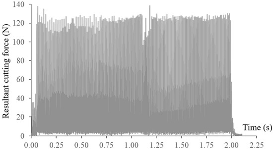
Figure 11.
Resultant cutting force in 1st tool path with feed rate scheduling.
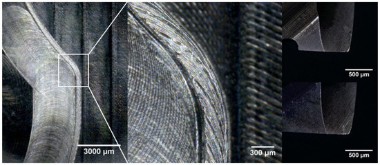
Figure 12.
Machined surface and tool condition with feed rate scheduling.
Most existing studies did not present a reliable method for determining cutting force or MRR thresholds for tool breakage prevention. On the contrary, the stress-based feed rate scheduling method introduced in this study regulates tool stress according to TRS of the end mill based on stress prediction. The tensile stress in the cutter can be controlled within a predefined fraction of its TRS through the feed rate scheduling method. Therefore, the method provides a reliable means of obtaining the time-optimal feed rates of the tool path while preventing tool breakages.
According to the general catalogue of the tooling company, the solid carbide end mill MS2MSD0300 can be used for machining of hardened steel with a hardness of 45–55 HRC. The recommended feed per tooth is 0.044 mm (264 mm/min), which is a rather conservative value, possibly due to the considerations of inconsistencies in the cutting process. Through the feed rate scheduling method, it is possible to achieve a 73.3% reduction in cutting time in the specific tool path compared to the recommended cutting conditions for the tested case.
4.2. 2nd Tool Path with Convex Curvature and Large Radial Cutting Depth
Another tool path with 1.2 mm radial cutting depth and convex curvature was investigated. The axial cutting depth was 0.3 mm and the spindle speed was 3000 rpm. The target contour and the corresponding tool path are shown in Figure 13.
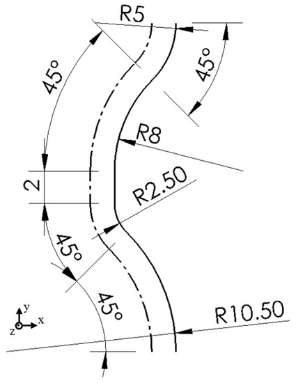
Figure 13.
The 2nd target contour (solid line) and corresponding tool path (chain line), dimensions in mm.
The original feed rate was set to be 420 mm/min (0.07 mm feed per tooth). According to the regression model, tool breakage was expected at the moment of machining the convex surface with the smallest radius of curvature in contrast with the first tool path. The predicted maximum tensile stress profile of the end mill along the tool path is illustrated in Figure 14.
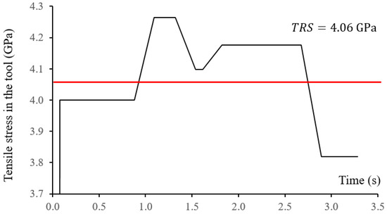
Figure 14.
Predicted tool stress along the 2nd tool path with constant feed rate.
The measured resultant cutting force and axial cutting force at a constant feed rate of 420 mm/min are shown in Figure 15. Breakage of the end mill can be identified due to significant increases in the cutting forces. Tool breakages happened at the arc interpolation segment with the smallest radius of 2.5 mm, which can also be observed from the machined surface. The broken tool was also inspected as presented in Figure 16. Tool breakages happened on both flutes of the end mill.
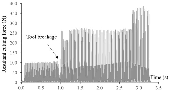
Figure 15.
Resultant cutting force 2nd tool path without feed rate scheduling.
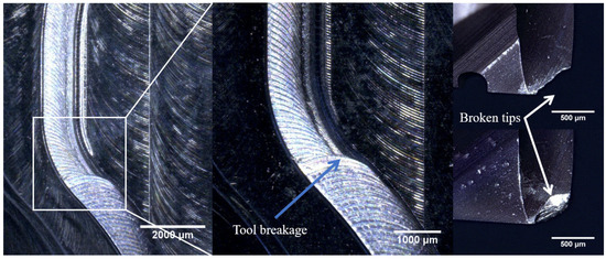
Figure 16.
Machined surface and the broken tool.
The scheduling of feed rates was conducted with the scaling factor of 0.9. The corresponding G-codes for the tool path with highlighted scheduled feed rates are shown in Table 5:
Table 5.
G-codes with feed rate scheduling for the 2nd tool path.
With the feed rate scheduling method, decreases of measured cutting forces were observed without tool breakage as shown in Figure 17. The machined surface and the condition of the end mill after machining are presented in Figure 18. Tool wear was observed at the tips of the end mill.
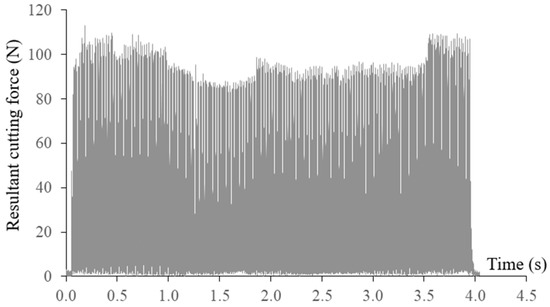
Figure 17.
Resultant cutting force in 2nd tool path with feed rate scheduling.
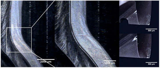
Figure 18.
Machined surface and tool condition with feed rate scheduling.
In the second tool path, the tool breakage occurred at the convex tool path segment with the smallest radius. However, in contrast with the previous tool path, it was observed that the end mill experienced relatively lower resultant cutting forces at the critical tool path segment due to the reduced maximum uncut chip thickness. This phenomenon demonstrates that the cutting forces could not reflect the tensile stress in the tool. High cutting force does not necessarily induce high tool stress. In this scenario with a large radial cutting depth of 1.2 mm, the high tensile stress in the cutting tool was primarily caused by the increase of uncut chip engaging angle at the critical tool path segment. In both tool paths with scheduled feed rates, the maximum tool stress was regulated at 90% of its TRS. However, the peak resultant cutting forces generally varied from 90 to 130 N due to the changes in tool engagement. Therefore, tool stress regulation is far more effective in preventing tool breakage than setting thresholds in cutting forces.
5. Discussion
In this study, a feed rate scheduling algorithm was formulated for mesoscale rough milling processes based on digitized stress function. Through the presented method, tool breakages in the cutting process can be eliminated at the optimum MRR. The maximum thickness and engaging angle of the uncut chip were found to have significant impacts on the tensile stresses and breakages on the cutting tool. Therefore, the planning of feed rates was achieved through regulating the based on the digitized maximum tensile stress rather than regulating cutting forces and MRR as presented in the existing studies.
Tool paths with linear segments and arc segments with various radii were investigated in validation experiments. It was observed that when machining at a constant feed rate and constant cutting depths, a significant change in radius of curvature could induce high stress in the tool. Compared with using the feed rate recommended by the tooling company, the method significantly reduces the machining time without causing tool breakage.
The cutting condition planning methodology presented in this study can be applied for metal cutting processes with various workpiece materials and cutting tools. The method will also be extended for conventional and microscale milling processes with complex tool trajectories such as splines in the near future. Up milling processes can be investigated considering the tool wear and wear-induced tool breakage. Metal cutting at high cutting speed can be further studied involving thermal effects for practical application. Cutting tools with low transverse rupture strength are more susceptible to breakages under high feed rates. The method could be more useful in cutting condition planning for cubic boron nitride and diamond tools with higher wear resistance yet lower transverse rupture strength than cemented carbide tools. Cutting tools with low transverse rupture strength are more susceptible to breakages under high feed rates, which makes the planning of feed rates have significant importance.
Author Contributions
Conceptualization, Y.G. and J.H.K.; methodology, Y.G., J.H.K. and H.P.L.; software, Y.G.; validation, Y.G., J.H.K. and H.P.L.; formal analysis, Y.G.; investigation, Y.G. and J.H.K.; resources, J.H.K. and H.P.L.; data curation, Y.G.; writing—original draft preparation, Y.G.; writing—review and editing, J.H.K. and H.P.L.; visualization, Y.G.; supervision, J.H.K. and H.P.L.; project administration, J.H.K. and H.P.L. All authors have read and agreed to the published version of the manuscript.
Funding
This research was funded by SIMTech project SC26/15-141018.
Institutional Review Board Statement
Not applicable.
Informed Consent Statement
Not applicable.
Data Availability Statement
Not applicable.
Acknowledgments
The research was supported by SIMTech, A*STAR. The first author was financially supported by the ASTAR Graduate Scholarship under ASTAR Graduate Academy.
Conflicts of Interest
The authors declare no conflict of interest.
Nomenclature
| FEM | finite element method |
| CEL | coupled Eulerian Lagrangian |
| MRR | material removal rate |
| radius of end mill | |
| feed per tooth | |
| uncut chip thickness | |
| angular position of end mill | |
| axial cutting depth | |
| radial cutting depth | |
| spindle speed | |
| transverse rupture strength | |
| uncut chip engaging angle | |
| maximum uncut chip thickness | |
| tool entry angle respect to instantaneous feed direction | |
| actual feed per tooth experienced by the tip of the end mill | |
| maximum tensile stress in the cutting tool | |
| scaling factor for tool stress | |
| feed rate | |
| length of transition for linear interpolation | |
| length of transition for arc interpolation |
References
- Wang, W.P. Solid modeling for optimizing metal removal of three-dimensional NC end milling. J. Manuf. Syst. 1988, 7, 57–65. [Google Scholar] [CrossRef]
- Karunakaran, K.; Shringi, R. A solid model-based off-line adaptive controller for feed rate scheduling for milling process. J. Mater. Process. Technol. 2008, 204, 384–396. [Google Scholar] [CrossRef]
- Li, Z.; Zheng, M.; Zheng, L.; Wu, Z.; Liu, D. A solid model-based milling process simulation and optimization system integrated with CAD/CAM. J. Mater. Process. Technol. 2003, 138, 513–517. [Google Scholar] [CrossRef]
- Ridwan, F.; Xu, X.; Ho, F.C.L. Adaptive execution of an NC program with feed rate optimization. Int. J. Adv. Manuf. Technol. 2012, 63, 1117–1130. [Google Scholar] [CrossRef]
- Spence, A.; Altintas, Y. A solid modeller based milling process simulation and planning system. J. Eng. Ind. 1994, 116, 61–69. [Google Scholar] [CrossRef]
- Lee, H.U.; Cho, D.W. Development of a reference cutting force model for rough milling feedrate scheduling using FEM analysis. Int. J. Mach. Tools Manuf. 2007, 47, 158–167. [Google Scholar] [CrossRef]
- Ko, J.H.; Cho, D.-W. Feed rate scheduling model considering transverse rupture strength of a tool for 3D ball-end milling. Int. J. Mach. Tools Manuf. 2004, 44, 1047–1059. [Google Scholar] [CrossRef]
- Ko, J.H.; Yun, W.S.; Cho, D.-W. Off-line feed rate scheduling using virtual CNC based on an evaluation of cutting performance. Comput. Aided Des. 2003, 35, 383–393. [Google Scholar] [CrossRef]
- Lee, H.U.; Cho, D.-W. An intelligent feedrate scheduling based on virtual machining. Int. J. Adv. Manuf. Technol. 2003, 22, 873–882. [Google Scholar] [CrossRef]
- Mamedov, A.; Lazoglu, I. Micro ball-end milling of freeform titanium parts. Adv. Manuf. 2015, 3, 263–268. [Google Scholar] [CrossRef]
- Erdim, H.; Lazoglu, I. Offline force control and feedrate scheduling for complex free form surfaces in 5-axis milling. Procedia CIRP 2012, 1, 96–101. [Google Scholar]
- Özel, T.; Liu, X. Investigations on mechanics-based process planning of micro-end milling in machining mold cavities. Mater. Manuf. Process. 2009, 24, 1274–1281. [Google Scholar] [CrossRef]
- Liang, Y.; Ren, J.; Zhang, D.; Li, X.; Zhou, J. Mechanics-based feedrate scheduling for multi-axis plunge milling. Int. J. Adv. Manuf. Technol. 2015, 79, 123–133. [Google Scholar] [CrossRef]
- Ferry, W.; Altintas, Y. Virtual five-axis flank milling of jet engine impellers—Part II: Feed rate optimization of five-axis flank milling. J. Manuf. Sci. Eng. 2008, 130, 011013. [Google Scholar] [CrossRef]
- Li, Z.; Zhang, Z.; Zheng, L. Feedrate optimization for variant milling process based on cutting force prediction. Int. J. Adv. Manuf. Technol. 2004, 24, 541–552. [Google Scholar] [CrossRef]
- Fussell, B.; Jerard, R.; Hemmett, J. Robust feedrate selection for 3-axis NC machining using discrete models. J. Manuf. Sci. Eng. 2000, 123, 214–224. [Google Scholar] [CrossRef]
- Guzel, B.; Lazoglu, I. Increasing productivity in sculpture surface machining via off-line piecewise variable feedrate scheduling based on the force system model. Int. J. Mach. Tool. Manuf. 2004, 44, 21–28. [Google Scholar] [CrossRef]
- Erdim, H.; Lazoglu, I.; Ozturk, B. Feedrate scheduling strategies for free-form surfaces. Int. J. Mach. Tools Manuf. 2006, 46, 747–757. [Google Scholar] [CrossRef]
- Zhang, L.; Feng, J.; Wang, Y.; Chen, M. Feedrate scheduling strategy for free-form surface machining through an integrated geometric and mechanistic model. Int. J. Adv. Manuf. Technol. 2009, 40, 1191–1201. [Google Scholar] [CrossRef]
- Tikhon, M.; Ko, T.J.; Lee, S.H.; Kim, H.S. NURBS interpolator for constant material removal rate in open NC machine tools. Int. J. Mach. Tools Manuf. 2004, 44, 237–245. [Google Scholar] [CrossRef]
- Gao, Y.; Ko, J.H.; Lee, H.P. Meso-scale tool breakage prediction based on finite element stress analysis for shoulder milling of hardened steel. J. Manuf. Process. 2020, 55, 31–40. [Google Scholar] [CrossRef]
- Gao, Y.; Ko, J.H.; Lee, H.P. 3D coupled Eulerian-Lagrangian finite element analysis of end milling. Int. J. Adv. Manuf. Technol. 2018, 98, 849–857. [Google Scholar] [CrossRef]
- Burgoyne, H.A.; Daraio, C. Strain-rate-dependent model for the dynamic compression of elastoplastic spheres. Phys. Rev. E 2014, 89, 032203. [Google Scholar] [CrossRef] [PubMed]
- Thamizhmanii, S.; Bin Omar, B.; Saparudin, S.; Hasan, S. Surface roughness analyses on hard martensitic stainless steel by turning. J. Achiev. Mater. Manuf. Eng. 2008, 26, 139–142. [Google Scholar]
- Freedman, D.A. Statistical Models: Theory and Practice; Cambridge University Press: Cambridge, UK, 2009; p. 26. [Google Scholar]


Publisher’s Note: MDPI stays neutral with regard to jurisdictional claims in published maps and institutional affiliations. |
© 2021 by the authors. Licensee MDPI, Basel, Switzerland. This article is an open access article distributed under the terms and conditions of the Creative Commons Attribution (CC BY) license (http://creativecommons.org/licenses/by/4.0/).