
The Laser Alloying Process of Ductile Cast Iron Surface with Titanium


Welding Department, Faculty of Mechanical Engineering, Silesian University of Technology, Konarskiego Street 18A, 44-100 Gliwice, Poland
Metals 2021, 11(2), 282; https://doi.org/10.3390/met11020282
Submission received: 21 December 2020
/
Revised: 22 January 2021
/
Accepted: 4 February 2021
/
Published: 6 February 2021
(This article belongs to the Section Metal Casting, Forming and Heat Treatment)
Abstract
:The article presents the results of the laser alloying process of ductile cast iron EN-GJS 350-22 surface with titanium. The laser alloying process was conducted on 2 kW high power diode laser (HPDDL) Rofin Sinar DL02 with rectangular focus and uniform power density distribution in the focus axis. The laser alloying was conducted with constant laser beam power and processing speed with titanium powder feed rate variation. The tests of the produced surface layers included macrostructure and microstructure observations, X-ray diffraction (XRD) and energy dispersive spectroscopy (EDS) analysis, Vickers hardness, and solid particle erosion according to ASTM G76-04 standard. To assess the erosion mechanism, SEM observations of worn surfaces after erosive test were carried out. As a result of laser alloying of a ductile cast iron surface, the in situ metal-matrix composite structure was formed with TiC reinforcing particles. The microstructure change resulted in the increase of surface layers hardness and erosion resistance in comparison to the base material.
1. Introduction
Ductile cast irons (DCI) are materials commonly used in industries for machine parts, such as crankshafts, gears, or piston rings, due to their high mechanical and fatigue strengths, low tendency to stress concentration, vibration damping abilities, and good plastic properties. Ductile irons can also be formed relatively easily and cheaply, as they exhibit very good casting properties and machinability [1,2,3]. The main disadvantage of ductile cast irons in some applications is the insufficient wear resistance of the surface. Predominantly, in order to improve it, surface engineering techniques are used, such as electrolytic plasma technology, plasma spraying, gas spraying, and laser surface treatment [4,5,6,7].
Laser surface treatment is a widely used group of surface treatment technologies for a variety of materials and applications. Due to the use of a high power density laser beam as a heat source, technologies, such as laser surface hardening, melting, alloying, or cladding allows to obtain high and unique properties of the produced surface layers and coatings due to the rapid heating and cooling times of the processed materials [8,9]. In order to improve the wear resistance of the surface of materials, the methods of producing metal-matrix composite surface layers and coatings are used commonly [10,11,12,13]. The processes of laser cladding and alloying make it possible to produce both ex-situ and in situ metal-matrix composite surface layers and coatings. The in situ method uses metallurgical reactions, taking place in a pool of liquid metal with a specific chemical composition, which causes the precipitation of reinforcing particles during crystallization and cooling. This method, compared to the ex-situ method, eliminates the problems with the correct wetting and connection of ceramic particles in the metallic liquid, for example, related to their earlier oxidation. To produce in situ metal-matrix composite structure it is necessary to obtain a pool of liquid metal with a specific chemical composition that allows the reactions leading to the precipitation of ceramic particles. Due to the high dynamics of heating and cooling during laser surface treatment, it is also necessary that the reaction takes place in a relatively short time [14,15].
Among the laser surface treatment processes, ductile cast irons are mainly processed by laser surface melting and alloying, which, due to rapid cooling of liquid metal, cause the formation of non-equilibrium structures with unique properties [16,17,18]. Among these processes, laser alloying allows to change the chemical composition in the area of the surface layer and to produce a metal-matrix composite structure in this area [19,20]. Due to the high carbon content in ductile irons chemical composition and high titanium to carbon affinity, with the titanium addition using laser surface alloying process, in situ metal-matrix composite surface layer can be produced. Previously Liu [21] and Park [22] conducted research about in situ formation of TiC reinforcement in grey cast iron surface layer by a laser surface alloying process. Janicki proved that by laser alloying of ferritic–pearlitic ductile cast iron surface with titanium, TiC-reinforced homogenous surface layers can be produced [23,24]. It has also been proven that the process of alloying ductile cast iron with titanium has a positive effect on tribological properties [25].
The purpose of this research is to determine the effect of the parameters of the laser alloying of ductile iron EN GJS 350-22 surface with titanium on the macrostructure, microstructure, hardness, and erosion resistance of the manufactured surface layers.
2. Materials and Methods
The EN GJS-350-22 grade ductile cast iron was used for the tests. The chemical composition of the base is shown in Table 1, while the structure is shown in Figure 1. The structure used for the tested ductile cast iron was composed of a ferritic matrix with about 20 vol.% of 65 µm diameter spheroidal graphite precipitates. For the laser surface alloying process, H.C. Starck AMPERIT 154, 99.0% pure titanium powder with 45 ÷ 70 µm gradation was used. The base material surface was prepared by grinding with a horizontal axis-grinding machine to a surface finish of 0.5 μm Ra and degreasing with ethyl alcohol before the laser surface alloying process. The titanium powder was dried for one hour at 50 °C.
The laser surface alloying process was carried out using a laboratory stand equipped with a high-power HPDL Rofin Sinar DL02 diode laser (Rofin-Sinar Laser GmbH, Hamburg, Germany) (Table 2) with a direct beam transmission to the treated surface. The maximum output power of the used laser was 2000 W. The beam of this laser had a rectangular focus with dimensions of 6.8 mm × 1.8 mm and a uniform density distribution along the focus axis. The beam profile was measured with a Prometec Laserscope UFF100 (Prometec GmbH, Aachen, Germany). The station was also equipped with a numerically controlled positioning system for the laser head and the processed material. The short axis of the laser beam was set parallel to the traverse direction. The laser head was stationary; the linear movement of the table with a set alloying speed was performed by the CNC positioning system. For the powder feeding, a disk powder feeding system with a vibrator was used. Titanium powder was fed directly into the area of impact of the laser beam at an angle of 45° to the treated surface. In order to ensure that the powder was evenly supplied to the liquid metal pool, the nozzle used had a shape adapted to the shape and size of the laser beam focus. The laser beam was focused on the surface of the processed substrate. As the shielding and transporting gas, argon was used with the flow rate of 15 L/min and 3 L/min, respectively. The single-bead surface layers were produced with a 2000 W power laser beam, 0.075 m/min alloying speed and powder feed rate of 4–20 mg/mm (Table 3). All surface layers were produced without preheating of the substrate.
The macrostructure observations of the produced surface layers were carried out on an optical stereoscopic microscope Olympus SZX9 (Olympus, Tokio, Japan). The geometrical parameters of the laser alloyed layers were measured using AutoCAD 2018 software (Autodesk, CA, USA), the in situ formed particles content in the structure was analyzed using Image-Pro Plus 4.5.0.29 software (Media Cybernetics, Inc., Rockville, MD, USA). The microstructure of surface layers was investigated using scanning electron microscope Phenom World PRO (Thermo Fisher Scientific, Waltham, MA, USA) equipped with BSE (Backscattered Electrons) energy dispersive spectroscopy (EDS). The XRD analysis was carried out using a PANalytical X’Pert PRO diffraction system (Malvern Panalitycal, Malvern, UK), using filtered radiation from the lamp with cobalt anode. The X-ray diffraction patterns were recorded from the ground coatings surfaces. The diffraction profiles were obtained in 2θ range between 35 and 120° in continuous scan mode with a step size of 0.0525°. The counting time per each step was 19.38 s. The Vickers hardness was measured for each uniform surface layer with the load of 200 g and dwell time of 10 s using Wilson Wolpert 401 MVD tester (Wilson Instruments, Instron Company, Norwood, MA, USA). The Vickers hardness measurements were conducted in one line according to a scheme (Figure 2). The average hardness and standard deviation were calculated from 10 measurements in each surface layer and base material.
The solid-particle erosive test of all homogenous surface layers and base material (as reference material) was conducted in accordance with ASTM G76-04 standard [26]. The scheme of the used test stand is presented in Figure 3. The erodent material used for the test was angular Al2O3 with the average particle size of 50 μm in a stream of dry compressed air. The velocity of erodent was 70 m/s and erodent material feed rate was 2 g/min. The erodent material was led to the material surface with a 1.5 mm diameter and 50 mm length nozzle. The distance between the nozzle and the tested surface was 10 mm. The erosive tests were carried out with the 30° and 90° impingement angles for 10 min. For each angle, three tests were carried out. As a result of the solid particle erosive test, a mass loss was obtained using a laboratory-scale with a 0.0001 g accuracy. The erosion rate was counted according to the ASTM G76-04 standard. The surface craters received after erosive tests were investigated using a scanning electron microscope to define the wear mechanism of the produced surface layers.
3. Results and Discussion
The macrostructures of the cross-sections of fabricated surface layers are presented in Figure 4. The geometrical parameters of the produced single-bead surface layers are presented in Table 4. The shape of the fusion zones of the laser alloyed surface layers is hemispherical. During laser processing, the surface tension gradient is the main mechanism of fluid flow (Marangoni effect). Based on the fusion shape of surface layers, it can be stated that the surface tension was the highest in a central area of the molten pool. The increase of titanium powder feed rate led to an increase of all geometrical parameters. Bead width varied between 6.1 and 6.6 mm, bead depth between 1.2 and 1.6 mm, and bead area between 5.5 and 9.2 mm2. Out of all produced single-bead surface layers, only layer T5 was not homogeneous (laser power 2000 W, speed 0.075 m/min, and powder feed rate 20 mg/mm). For the used laser power and process speed values, the powder feed rate of 20 mg/mm was excessive to receive uniform titanium powder distribution in a surface layer volume by convective mass transport. As a result of the laser alloying process, the titanium was distributed throughout the liquid volume and in situ formed precipitates can be observed throughout the cross-sections of each surface layer.
The microstructure of the laser alloyed surface layers is presented in Figure 5. The laser alloying of the DCI surface with titanium caused the microstructure change in comparison to the base material. As a result of heating by laser beam, the DCI surface melted and graphite precipitates dissolved in liquid metal. Simultaneous enrichment of molten pool with titanium resulted in the formation of reinforcing particles by metallurgical reactions in liquid metal during rapid cooling and crystallization. The microstructure of produced surface layers consists of matrix and in situ formed reinforcing particles. The fine-grained matrix structure consisted of primary austenite dendrites, partly after martensitic transformation and ledeburite in interdendritic spaces. The XRD analysis (Figure 6) confirmed the austenite occurrence. According to the EDS (Figure 7) and XRD (Figure 6) analyses, in situ formed precipitates are titanium carbides (TiC). On the SEM micrographs, the impact of the process parameters (titanium powder feed rate) on the size and the morphology of TiC particles can be observed. The TiC precipitates formed in surface layers produced with lower powder feed rate 4 and 8 mg/mm (designation T1 and T2, respectively) show cubic morphology. The powder feed rate increase to 16 mg/mm led to change the morphology of TiC precipitates to dendritic. The precipitates morphology change is mostly associated with titanium content in the surface layers. Based on low magnification SEM micrographs from four surface layers areas (two top areas and two bottom areas), the precipitates average volume fraction was measured (Table 5). The average titanium content was received from surface EDS analysis on four areas of each surface layer. The results show that with the titanium powder feed rate increase, the average Ti content, and average precipitates volume fraction increases. With the use of laser surface alloying with 2000 W laser beam, 0.075 m/min speed, and Ti powder feed rate variation between 4 and 16 mg/mm, the surface layers with the Ti content of 3.2–12.9 wt.%, and TiC precipitates fraction of 5.5–20.1 vol.% can be produced.
The average Vickers hardness of produced laser alloyed surface layers is presented in Figure 8. Depending on the applied titanium powder feed rate, varying between 4 and 16 mg/mm, for producing single-bead surface layers with 2000 W laser beam power and process speed of 0.075 m/min, the average hardness of produced surface layers was in a range of 690 to 730.2 HV0.2. The lowest hardness was measured for the T3 surface layer (powder feed rate 12 mg/mm) and the highest for the T4 surface layer (powder feed rate 16 mg/mm). The surface layer with the highest Ti content and TiC precipitates fraction show the highest hardness out of all tested layers. The lowest standard deviation of the hardness results showed the T1 surface layer (powder feed rate 4 mg/mm), which also was characterized by the lowest volume fraction of hard TiC precipitates in the structure. With the powder feed rate, titanium content, and precipitates fraction increase, the hardness standard deviation increased due to the higher fraction of hard precipitates in the matrix. The process of laser surface alloying of the ductile cast iron EN GJS 350-22 surface with titanium resulted in about a 300% hardness increase of the base material. The contribution of hardness from the surface across the surface layer to base material is presented in Figure 9. Each of the produced homogeneous surface layers (T1, T2, T3, and T4) is characterized by uniform hardness contribution in the laser alloyed area due to the uniform structure and by the hardness decrease in the heat-affected zone and the base material. Due to the graphite precipitates occurring in the base material structure, the hardness contribution in this area was not uniform.
The average erosion rate results of laser alloyed surface layers and base material are presented in Figure 10. The laser alloying process of the ductile cast iron surface with titanium powder has a positive influence on increasing erosion resistance of the surface of this material. Each of the tested materials is characterized by a higher erosion rate during erosion with the 30° impingement angle in comparison to 90° angle, which is characteristic for the plastic erosion mechanism [28]. The erosion rates of laser alloyed surface layers are 0.45–0.56 mg/min and 0.36–0.42 mg/min for the 30° and 90° impingement angles, respectively. The reference material, ductile cast iron EN-GJS 350-22 show the average erosion rates of 0.88 mg/min and 0.48 mg/min for the 30° and 90° impingement angles, respectively. In both tested impingement angles, the lowest erosion rate was tested for T2 surface layer (laser beam power 2000 W, processing speed 0.075 m/min, powder feed rate 8 mg/mm). Out of all tested surface layers, the highest erosion rate was tested for T3 surface layer (laser beam power 2000 W, processing speed 0.075 m/min, powder feed rate 12 mg/mm) and for T4 surface layer (laser beam power 2000 W, processing speed 0.075 m/min, powder feed rate 16 mg/mm) for 30° and 90° impingement angle, respectively. Comparing the erosive wear results with the average hardness results, it can be observed that the base material is characterized by both the lowest average hardness and the highest erosion rate with both tested impingement angles. In case of produced surface layers, the T3 surface layer (powder feed rate 12 mg/mm), which is characterized by the lowest average hardness (out of surface layers) is also characterized by the highest erosion rate with the impingement angle of 30°. The lowest erosion rates with both tested impingement angles were received for the T2 surface layer (powder feed rate 8 mg/mm) with 713.6 HV0.2 average hardness. The received erosion rate and average hardness results are not precisely related, but the differences in both erosion rates and average hardness results between each tested surface layers are minor.
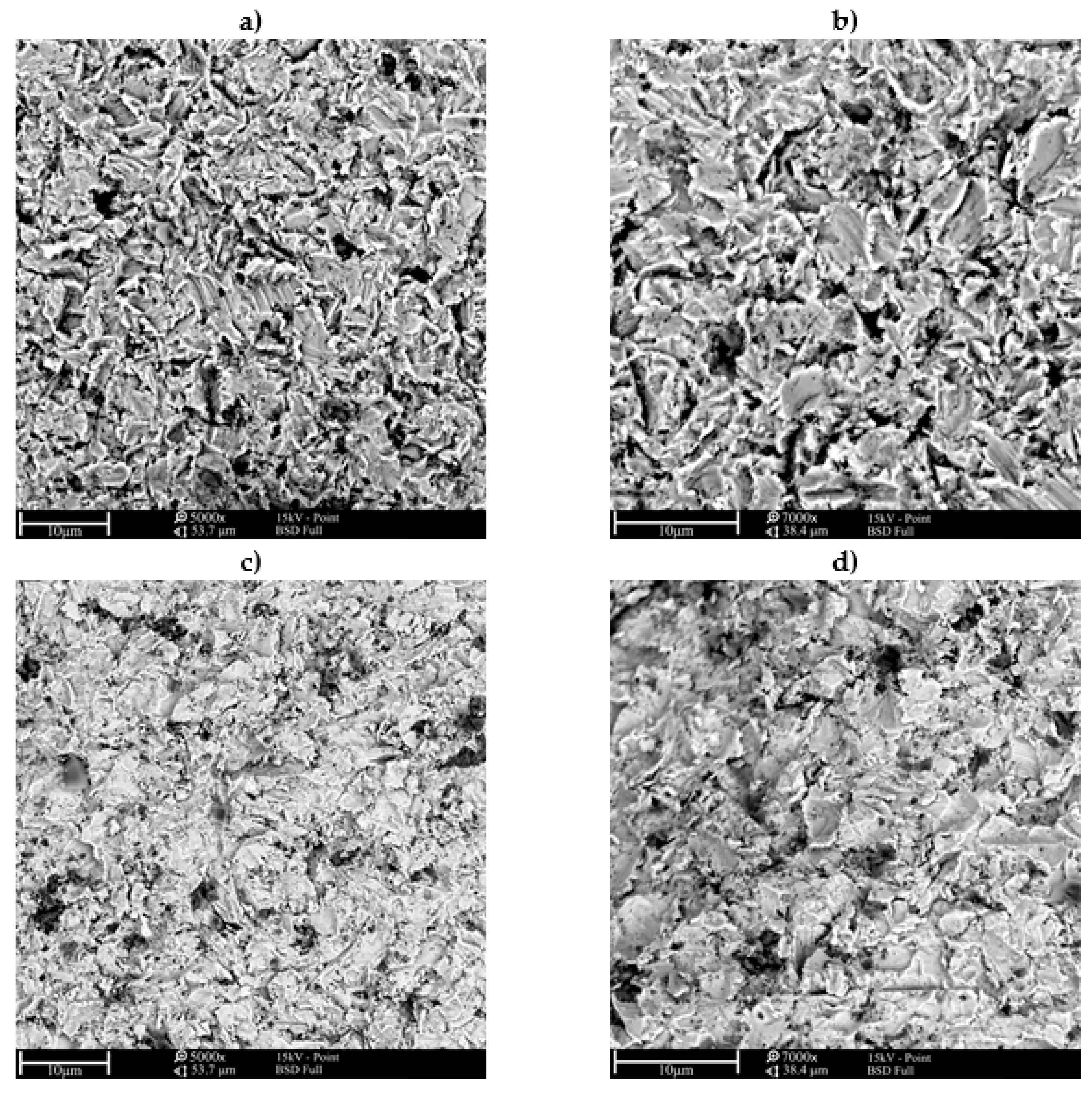
The SEM micrographs of craters surfaces after the solid particle erosive test are presented in Figure 11 and Figure 12. The SEM observations of craters allowed specifying the erosion mechanism of the tested surface layers and reference material. Plastic deformation occurred on each of the tested surfaces (both surface layers and ductile cast iron), which allowed to state that the erosion occurred in a ductile mode. In case of tests carried out with a 30° impingement angle on the laser alloyed worn surface (Figure 11a,b), long scars and narrow grooves can be observed. On the laser alloyed surface layers after erosion with 90° impingement angle, craters and grooves can be observed (Figure 12a,b). In comparison to laser alloyed surface layers, on the ductile cast iron worn surfaces, graphite can be observed. The SEM observations also confirmed that in the case of a base material, the erosive wear was more intensive in case of both impingement angles. In Figure 11c,d (impingement angle 30°) deeper craters and grooves can be observed while in Figure 12c,d (impingement angle 90°) deeper craters and flakes of material can be observed. In the worn ductile cast iron surface (tested with both impingement angles), embedded Al2O3 erosive particles can also be observed.
4. Conclusions
Based on the analysis of the results achieved, the following conclusions have been reached:
- As a result of the laser alloying process of the ductile cast iron EN GJS 350-22 surface with titanium, the single-bead surface layers characterized with hemi-spherical fusion shapes were produced. The shape of the laser alloyed surface layers proves that the surface tension gradient was the main mechanism of fluid flow and the surface tension was the highest in a central area of the molten pool.
- With the constant laser beam power and alloying speed, the increase of powder feed rate caused a slight increase of bead width, depth, and area.
- During the laser alloying process, the surface layer of the ductile cast iron was melted and the graphite dissolved in liquid metal, which caused carbon enrichment of the molten pool. The titanium addition resulted in fine TiC precipitates formation by metallurgical reactions during cooling and crystallization.
- The titanium powder feed rate change with constant laser beam power and processing speed had an influence on the quantity, fraction, size, and morphology of formed TiC particles. With the powder feed rate and titanium content increase, the TiC morphology change from cubic to dendritic, the particles size increased together with fraction in the surface matrix.
- The laser surface alloying process of the ductile cast iron with titanium resulted in about a 300% hardness increase in comparison to the base material. The powder feed rate has no significant influence on the average hardness of surface layers.
- The solid particle erosion tests show that laser surface alloying process had a positive influence on erosion resistance in comparison to the base material. The tests carried out with the 30° and 90° impingement angle show a minimum of 35% and 11% lower erosion rate of surface layers in comparison to the base material, respectively. The test results show that laser alloyed surface layers and base material are characterized by better erosion resistance with the 90° impingement angle than 30°, what is characteristic for plastic materials. The powder feed rate has no significant influence on surface layers erosion resistance.
- The craters SEM observations allowed assessing the ductile erosion mechanism of tested surface layers and base material. All observed worn surfaces indicate the plastic deformation of the surface structure during the interaction of accelerated erodent particles, while in the case of base material, the higher wear was observed.
Funding
Publication supported by internal fund of the Silesian University of Technology.
Institutional Review Board Statement
Not applicable.
Informed Consent Statement
Not applicable.
Data Availability Statement
Not applicable.
Conflicts of Interest
The author declares no conflict of interest.
References
- Petrus, Ł.; Bulanowki, A.; Kołakowski, J.; Brzeżański, M.; Urbanowicz, M.; Sobieraj, J.; Matuszkiewicz, G.; Szwalbe, L.; Janerka, K. The influence of selected melting parameters on the physical and chemical properties of cast iron. Arch. Foundry Eng. 2020, 17, 105–110. [Google Scholar]
- Żuk, M.; Górka, J.; Dojka, R.; Czupryński, A. Repair welding of cast iron coated electrodes. IOP Conf. Ser. Mater. Sci. Eng. 2017, 277, 012139. [Google Scholar] [CrossRef] [Green Version]
- Abboud, J.H. Microstructure and erosion characteristic of nodular cast iron surface modified by tungsten inert gas. Mater. Des. 2012, 35, 677–684. [Google Scholar] [CrossRef]
- Ayday, A.; Durman, M. Surface hardening of ductile cast iron by electrolytic plasma technology. Acta Phys. Pol. A 2013, 123, 291–293. [Google Scholar] [CrossRef]
- Joshi, S.S.; Choudhuri, D.; Mantri, S.A.; Banerjee, R.; Dahotre, N.B.; Banerjee, S. Rationalizing surface hardening of laser glazed grey cast iron via and integrated experimental and computational approach. Mater. Des. 2018, 156, 570–585. [Google Scholar] [CrossRef]
- Uyulgan, B.; Cetinel, H.; Ozdemir, I.; Tekmen, C.; Okumus, S.C.; Celik, E. Friction and wear properties of Mo coatings on cast-iron substrates. Surf. Coat. Technol. 2003, 174–175, 1082–1088. [Google Scholar] [CrossRef]
- Ksiazek, M.; Boron, L.; Tchorz, A. Microstructure, mechanical properties and wera behavior of High-Velocity Oxygen-Fuel (HVOF) sprayed (Cr3C2-NiCr + Al) composite coating on ductile cast iron. Coatings 2019, 9, 840. [Google Scholar] [CrossRef] [Green Version]
- Lisiecki, A.; Ślizak, D.; Kukofka, A. Laser cladding of Co-based metallic powder at cryogenic conditions. J. Achiev. Mater. Manuf. Eng. 2019, 95, 20–31. [Google Scholar] [CrossRef]
- Poloczek, T.; Kotarska, A. Effect of laser cladding parameters on structure properties of cobalt-based coatings. IOP Conf. Ser. Mater. Sci. Eng. 2020, 916, 012085. [Google Scholar] [CrossRef]
- Czupryński, A.; Adamiak, M.; Bayraktar, E.; Wyględacz, B. Comparison of tribological properties and structure of coatings produced in powder flame spraying process on grey cast iron. Weld. Technol. Rev. 2020, 92, 7–21. [Google Scholar] [CrossRef]
- Janicki, D. Laser cladding of Inconel 625-based composite coatings reinforced by porous chromium carbide particles. Opt. Laser Technol. 2017, 94, 6–14. [Google Scholar] [CrossRef]
- Lisiecki, A.; Ślizak, D.; Kukofka, A. Robotized fiber laser cladding of steel substrate by metal matrix composite powder at cryogenic conditions. Mater. Perform. Charact. 2019, 8, 1214–1225. [Google Scholar] [CrossRef]
- Czupryński, A. Comparison of properties of hardfaced layers made by a metal-core-covered tubular electrode with a special chemical composition. Materials 2020, 13, 5445. [Google Scholar] [CrossRef]
- Jeyaprakash, N.; Yang, C.-H.; Duraiselvam, M.; Prabu, G. Microstructure and tribological evolution during laser alloying WC—12% Co and Cr3C2—25% NiCr powders on nodular iron surface. Results Phys. 2019, 12, 1610–1620. [Google Scholar] [CrossRef]
- Janicki, D. Fabrication of high chromium white iron surface layers on ductile cast iron substrate by laser surface alloying. Stroj. Vestn. J. Mech. E 2017, 63, 705–714. [Google Scholar]
- Janicki, D. Shaping the Structure and Properties of Surface Layers of Ductile Cast Iron by Laser Alloying; Wydawnictwo Politechniki Śląskiej: Gliwice, Poland, 2018; pp. 39–106. [Google Scholar]
- Kotarska, A.; Janicki, D.; Górka, J.; Poloczek, T. Solid particle erosion of laser surface melted ductile cast iron. Arch. Foundry Eng. 2020, 20, 105–111. [Google Scholar]
- Alabeedi, K.F.; Abboud, J.H.; Benyounis, K.Y. Microstructure and erosion resistance enhancement of nodular cast iron by laser melting. Wear 2009, 266, 925–933. [Google Scholar] [CrossRef]
- Sun, G.; Zhou, R.; Li, P.; Feng, A.; Zhang, Y. Laser surface alloying of C-B-W-Cr powders on nodular cast iron rolls. Surf. Coat. Technol. 2011, 205, 2747–2754. [Google Scholar] [CrossRef]
- Yan, H.; Wang, A.; Xiong, Z.; Xu, K.; Huang, Z. Microstructure and wear resistance of composite layers on a ductile iron with multicarbide by laser surface alloying. Appl. Surf. Sci. 2010, 256, 7001–7009. [Google Scholar] [CrossRef]
- Liu, Y.; Qu, Q.; Su, Y. TiC reinforcement composite coating produced using graphite of the cast iron by laser cladding. Materials 2016, 9, 815. [Google Scholar] [CrossRef] [Green Version]
- Park, H.; Nakata, K.; Tomida, S. In situ formation of TiC particulate composite layer on cast iron by laser alloying of thermal sprayed titanium coating. J. Mater. Sci. 2000, 35, 747–755. [Google Scholar] [CrossRef]
- Janicki, D. Microstructural evolution during laser surface alloying of ductile cast iron with titanium. Arch. Metall. Mater. 2017, 62, 2425–2431. [Google Scholar] [CrossRef] [Green Version]
- Janicki, D. In-situ synthesis of titanium carbide particles in an iron matrix during diode-laser surface alloying of ductile cast iron. Mater. Technol. 2017, 51, 317–321. [Google Scholar] [CrossRef]
- Janicki, D. Microstructure and sliding wear behaviour of in-situ TiC-reinforced composite surface layers fabricated on ductile cast iron by laser alloying. Materials 2018, 11, 75. [Google Scholar] [CrossRef] [PubMed] [Green Version]
- ASTM International. ASTM G76-04, Standard Test Method for Conducting Erosion Tests by Solid Particle Impingement Using Gas Jets; ASTM International: West Conshohocken, PA, USA, 2004. [Google Scholar]
- Biswas, S.; Satapathy, A. A comparative study on erosion characteristics of red mud filled bamboo-epoxy and glass-epoxy composites. Mater. Des. 2010, 4, 1752–1767. [Google Scholar] [CrossRef]
- Stachowiak, G.W.; Batchelor, A.W. Engineering Tribology, 4th ed.; Butterworth-Heinemann: Oxford, UK, 2014; pp. 551–556. [Google Scholar]
Figure 1.
The ductile cast iron EN GJS-350-22 microstructure (optical microscope).

Figure 2.
The Vickers hardness measurements scheme.
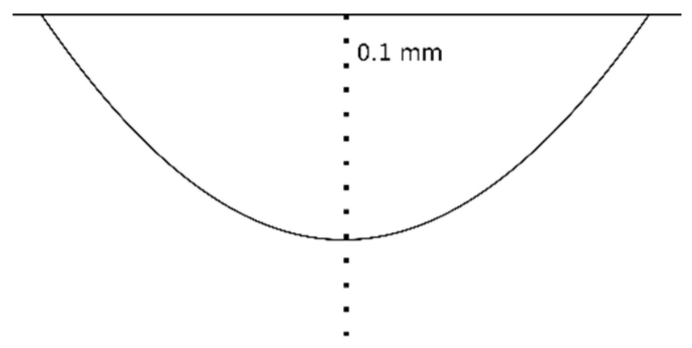
Figure 3.
Scheme of the solid particle erosive test stand. Reprinted with permission from ref. [27]. Copyright 2010 Elsevier.
Figure 3.
Scheme of the solid particle erosive test stand. Reprinted with permission from ref. [27]. Copyright 2010 Elsevier.

Figure 4.
The macrostructure of laser alloyed surface layers (designation in accordance with Table 2).
Figure 4.
The macrostructure of laser alloyed surface layers (designation in accordance with Table 2).
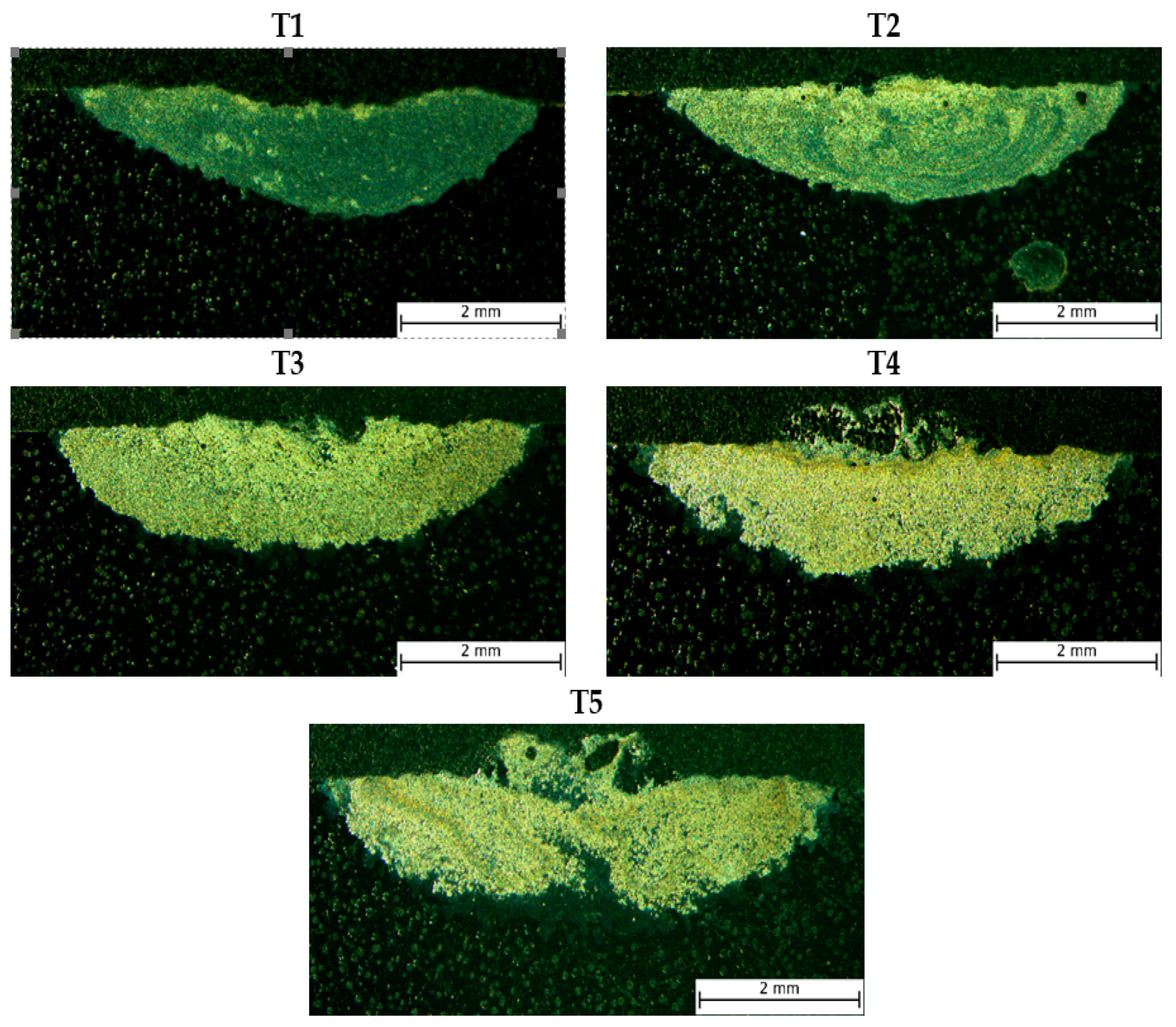
Figure 5.
The microstructure of homogeneous laser alloyed surface layers (designation in accordance with Table 3).
Figure 5.
The microstructure of homogeneous laser alloyed surface layers (designation in accordance with Table 3).
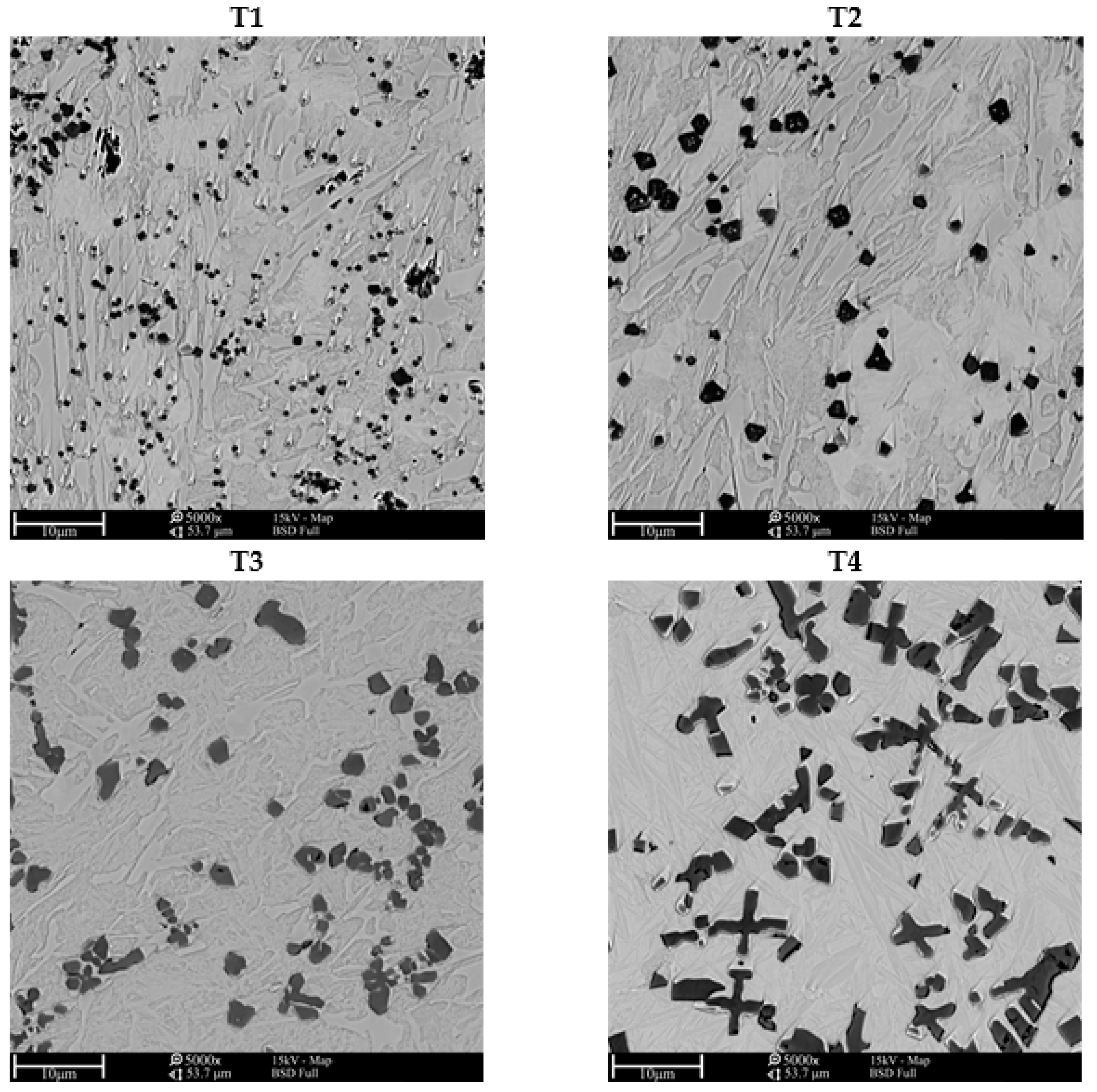
Figure 6.
The XRD pattern of surface layer alloyed with 2000 W laser beam, 0.075 speed and 12 mg/mm Ti powder feed rate.
Figure 6.
The XRD pattern of surface layer alloyed with 2000 W laser beam, 0.075 speed and 12 mg/mm Ti powder feed rate.
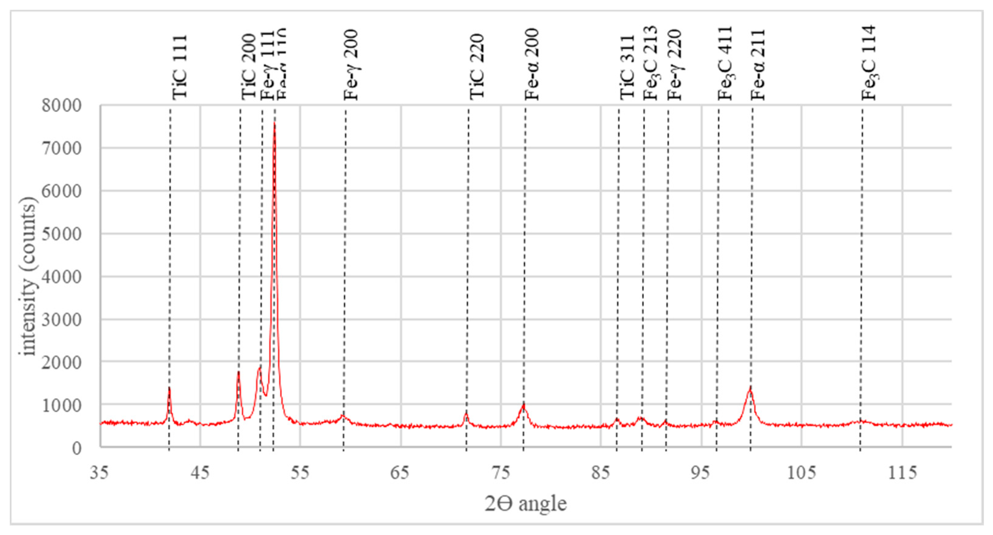
Figure 7.
The energy dispersive spectroscopy (EDS) surface analysis result of the representative laser alloyed surface layer.
Figure 7.
The energy dispersive spectroscopy (EDS) surface analysis result of the representative laser alloyed surface layer.
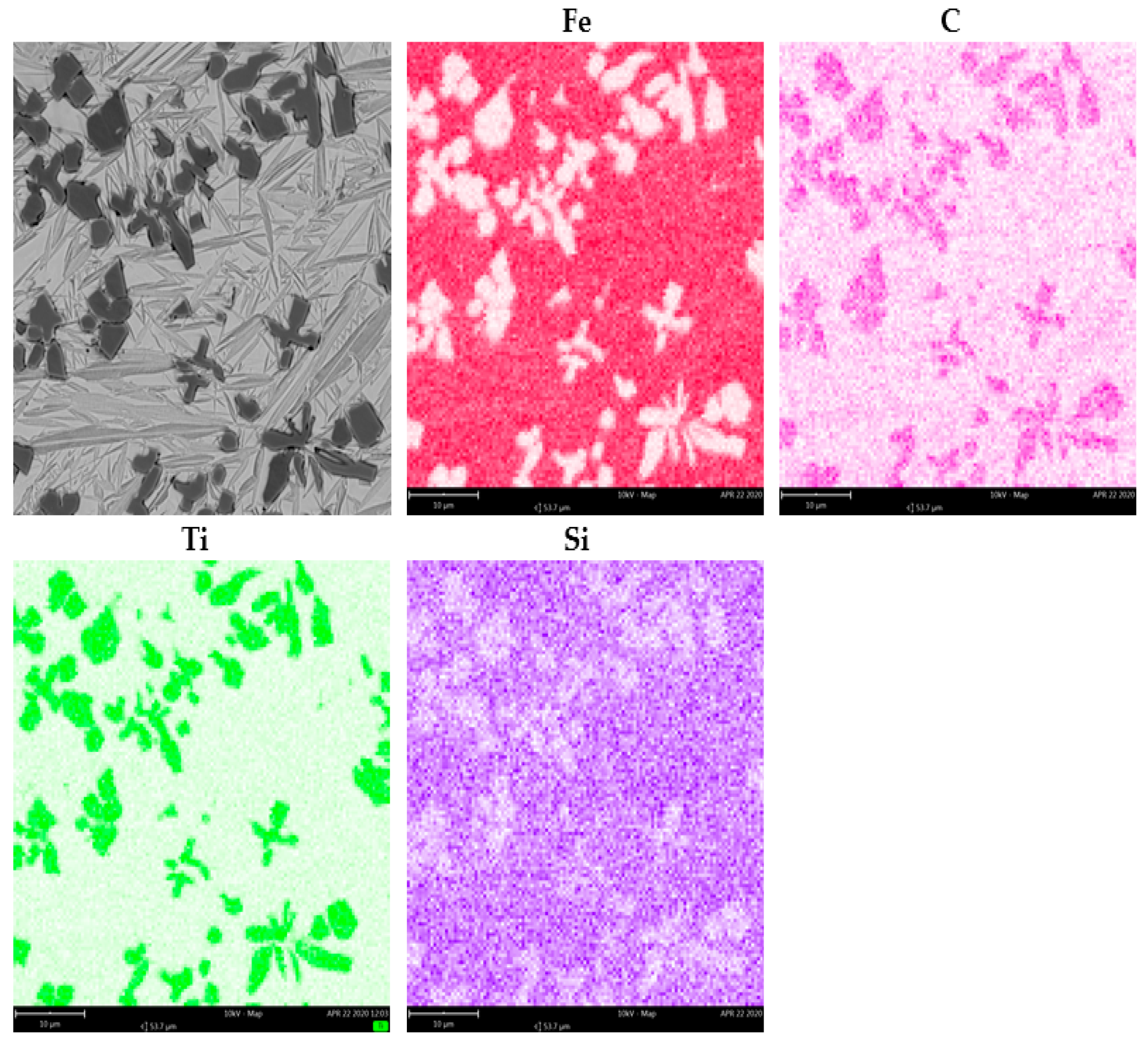
Figure 8.
The average and standard deviation Vickers hardness of laser alloyed surface layers results (designation in accordance with Table 3).
Figure 8.
The average and standard deviation Vickers hardness of laser alloyed surface layers results (designation in accordance with Table 3).
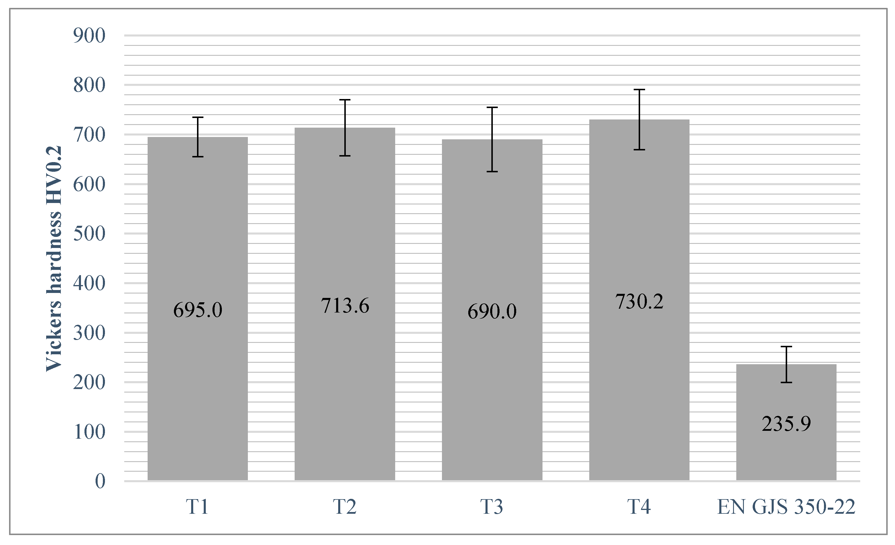
Figure 9.
The laser alloyed surface layers hardness contribution (designation in accordance with Table 3).
Figure 9.
The laser alloyed surface layers hardness contribution (designation in accordance with Table 3).
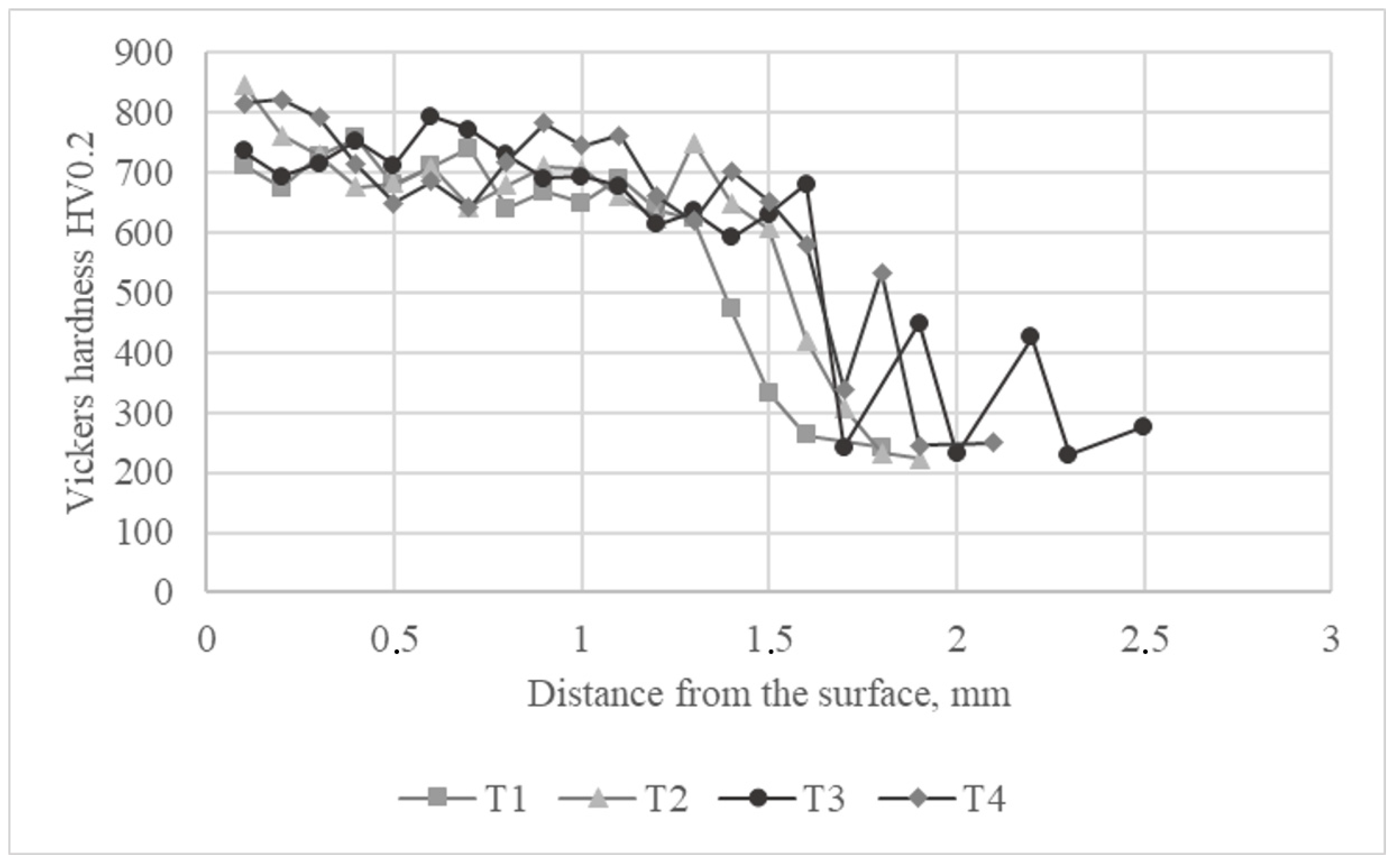
Figure 10.
Average erosion rate results of tested laser alloyed surface layers and reference material.
Figure 10.
Average erosion rate results of tested laser alloyed surface layers and reference material.
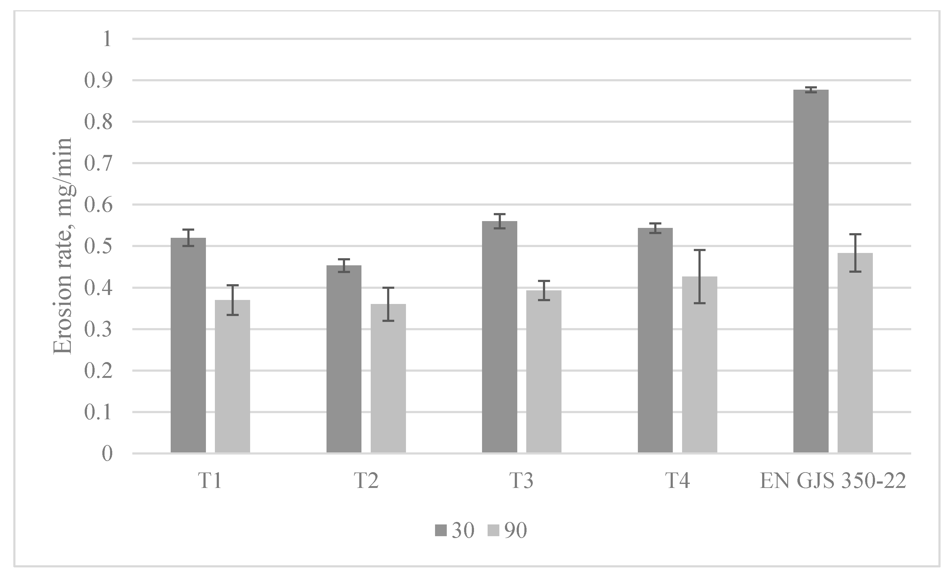
Figure 11.
The SEM micrographs of worn surfaces after erosive tests with the impingement angle 30°; (a,b) representative surface layer; (c,d) reference material EN GJS 350-22.
Figure 11.
The SEM micrographs of worn surfaces after erosive tests with the impingement angle 30°; (a,b) representative surface layer; (c,d) reference material EN GJS 350-22.

Figure 12.
The SEM micrographs of worn surfaces after erosive tests with the impingement angle 90°; (a,b) representative surface layer; (c,d) reference material EN GJS 350-22.
Figure 12.
The SEM micrographs of worn surfaces after erosive tests with the impingement angle 90°; (a,b) representative surface layer; (c,d) reference material EN GJS 350-22.

Table 1.
The EN GJS-350-22 ductile cast iron chemical composition.
| Chemical Composition, wt.% | ||||||||
|---|---|---|---|---|---|---|---|---|
| C | Si | Mn | P | S | Cu | Ti | Mg | Cr |
| 3.66 | 2.71 | 0.527 | 0.042 | 0.001 | 0.068 | 0.032 | 0.012 | 0.124 |
Table 2.
Technical specifications of HPDL Rofin Sinar DL02 diode laser.
| Manufacturer | Rofin-Sinar Laser GmbH |
|---|---|
| The wavelength of the laser radiation, nm | 808 ÷ 940 ± 5 |
| Maximum output power, W | 2000 |
| Range of laser power, W | 100 ÷ 2000 |
| Focal length, mm | 82 |
| Laser beam spot size, mm | 1.8 × 6.8 |
| Range of laser power intensity, W/mm2 | 10.1 ÷ 202.0 |
Table 3.
Laser surface alloying process parameters.
| Designation | Laser beam Power, W | Laser Alloying Speed, m/min | Powder Feed Rate, mg/mm | Homogeneity |
|---|---|---|---|---|
| T1 | 2000 | 0.075 | 4 | Yes |
| T2 | 2000 | 0.075 | 8 | Yes |
| T3 | 2000 | 0.075 | 12 | Yes |
| T4 | 2000 | 0.075 | 16 | Yes |
| T5 | 2000 | 0.075 | 20 | No |
Table 4.
Laser surface alloying process parameters.
| Designation (Table 3) | Bead Width, mm | Bead Depth, mm | Bead Area, mm2 |
|---|---|---|---|
| T1 | 6.1 | 1.2 | 5.5 |
| T2 | 6.1 | 1.4 | 5.9 |
| T3 | 6.3 | 1.4 | 7.1 |
| T4 | 6.4 | 1.6 | 7.9 |
| T5 | 6.6 | 1.6 | 9.2 |
Table 5.
The average titanium content and precipitates volume fraction in laser alloyed surface layers.
Table 5.
The average titanium content and precipitates volume fraction in laser alloyed surface layers.
| Designation (Table 3) | Average Titanium Content, wt.% | Average Precipitates Fraction, vol.% |
|---|---|---|
| T1 | 3.2 ± 0.3 | 5.5 ± 1.1 |
| T2 | 5.5 ± 1.7 | 9.6 ± 2.3 |
| T3 | 9.1 ± 2.8 | 14.1 ± 3.9 |
| T4 | 12.9 ± 1.7 | 20.1 ± 2.3 |
Publisher’s Note: MDPI stays neutral with regard to jurisdictional claims in published maps and institutional affiliations. |
© 2021 by the author. Licensee MDPI, Basel, Switzerland. This article is an open access article distributed under the terms and conditions of the Creative Commons Attribution (CC BY) license (http://creativecommons.org/licenses/by/4.0/).
Share and Cite
MDPI and ACS Style
Kotarska, A. The Laser Alloying Process of Ductile Cast Iron Surface with Titanium. Metals 2021, 11, 282. https://doi.org/10.3390/met11020282
AMA Style
Kotarska A. The Laser Alloying Process of Ductile Cast Iron Surface with Titanium. Metals. 2021; 11(2):282. https://doi.org/10.3390/met11020282
Chicago/Turabian StyleKotarska, Aleksandra. 2021. "The Laser Alloying Process of Ductile Cast Iron Surface with Titanium" Metals 11, no. 2: 282. https://doi.org/10.3390/met11020282
Note that from the first issue of 2016, this journal uses article numbers instead of page numbers. See further details here.