
Galvanic Sensor for Detecting Corrosion during Acid Cleaning of Magnetite in Steam Boilers


Abstract
:1. Introduction
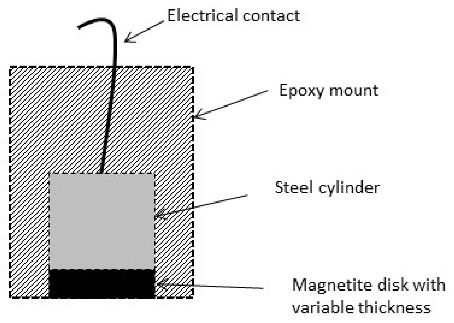
2. Experimental
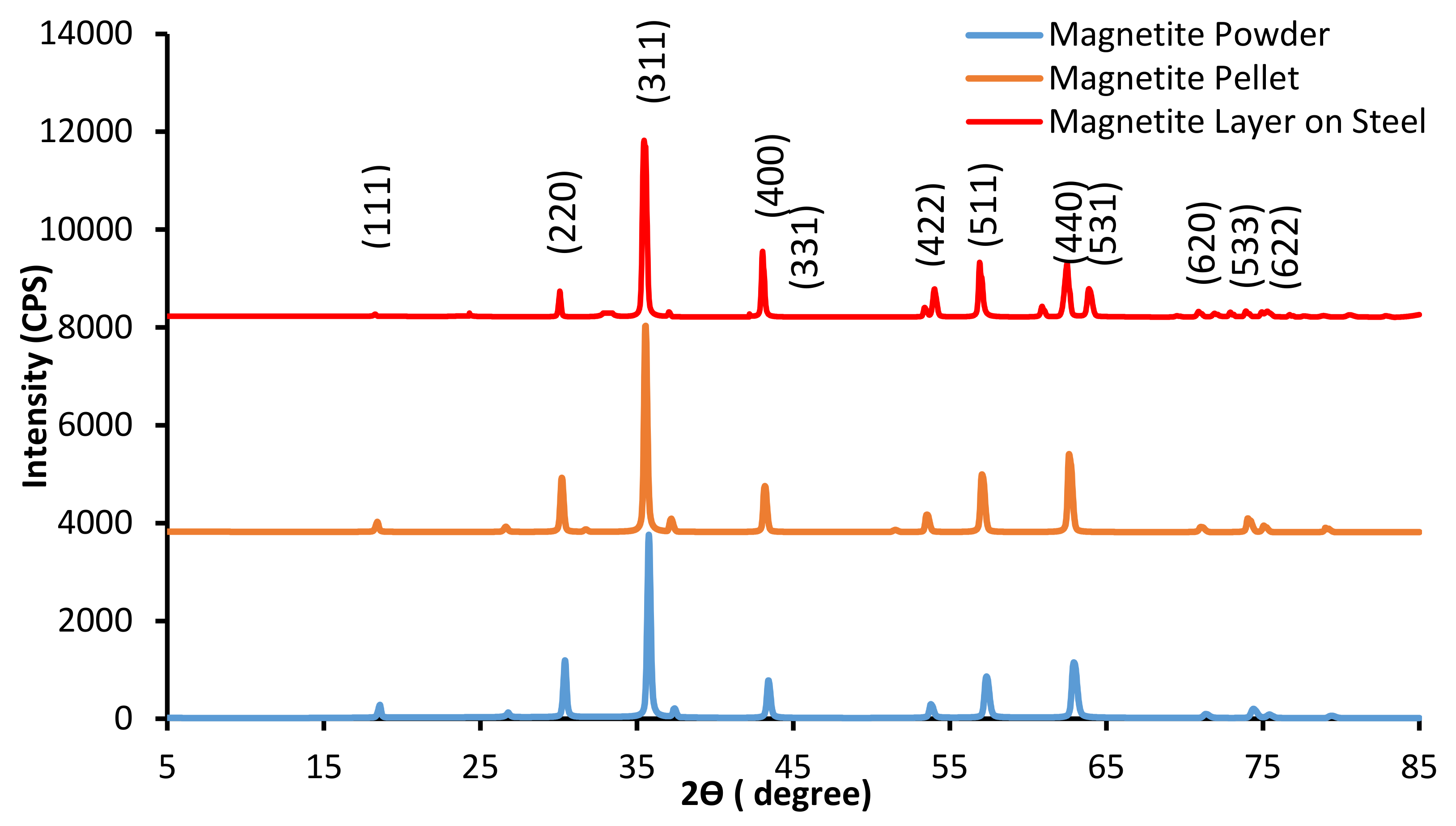
3. Results and Discussion
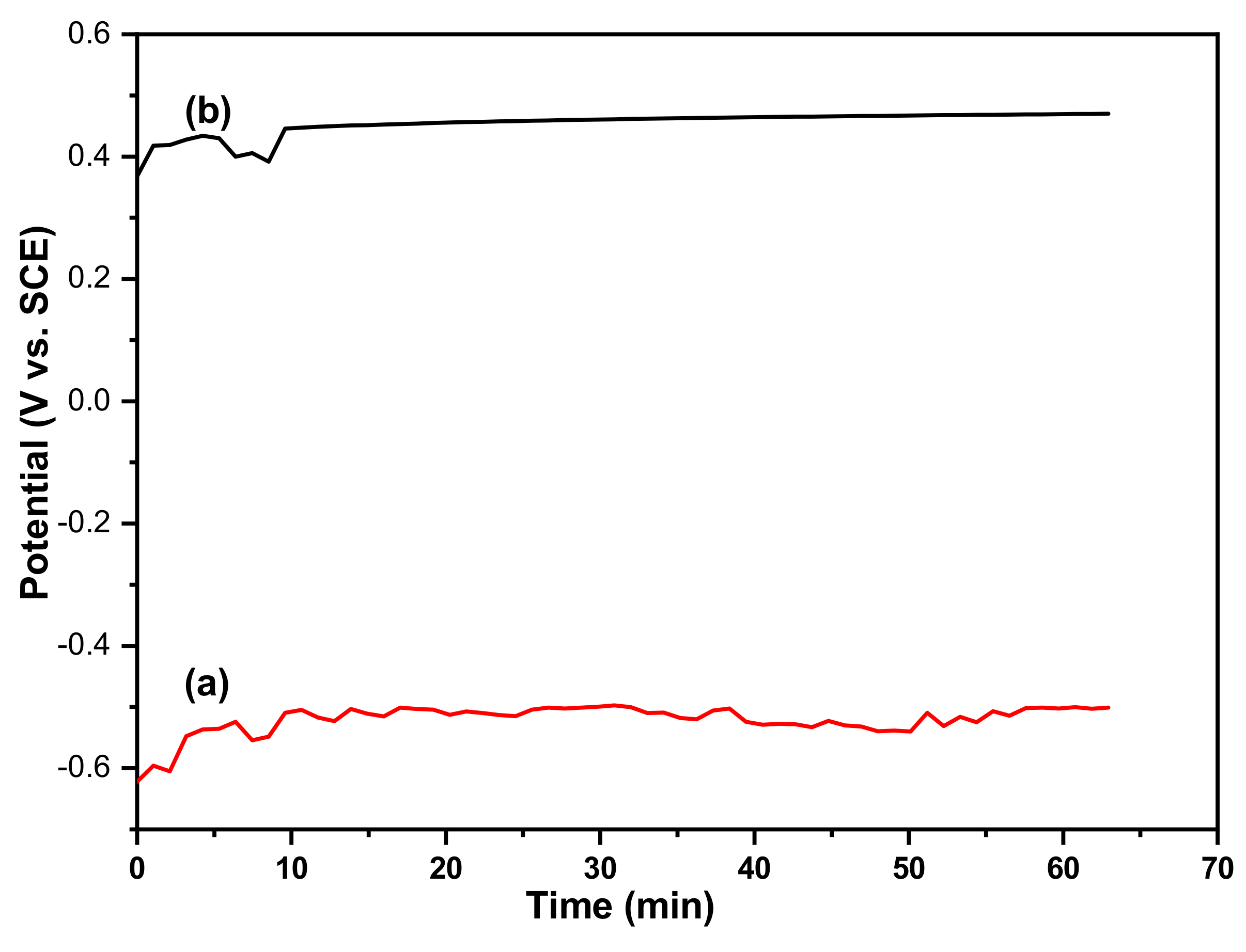
3.1. Electrochemical Measurements with the Magnetite/Iron Couple
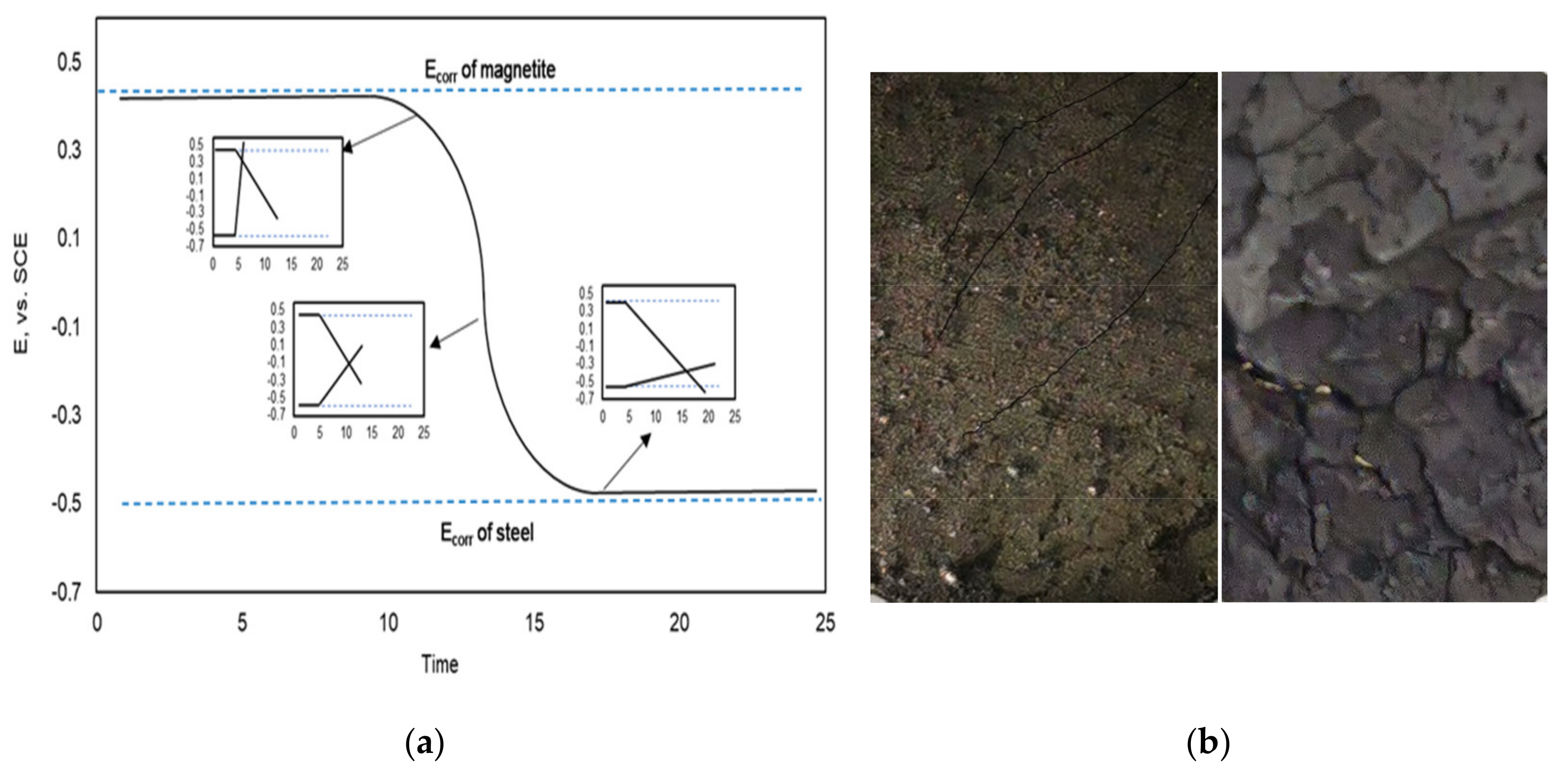
3.2. Application of the Sensor in a Boiler Tube
4. Conclusions
Author Contributions
Funding
Institutional Review Board Statement
Informed Consent Statement
Data Availability Statement
Acknowledgments
Conflicts of Interest
References
- Boiler Cleaning/Chemical Cleaning and Descaling. Available online: https://boilercleaning.wordpress.com/chemical-cleaning-and-descaling (accessed on 18 February 2021).
- Buecker, B. Select the proper boiler cleaning solvent. Chem. Eng. Prog. 2001, 97, 48–52. [Google Scholar]
- Tahir, M.S.; Saleem, M. Experimental study of chemical de-scaling-I: effect of acid concentration. J. Fac. Eng. Technol. 2008, 2007, 1–9. [Google Scholar]
- Trabanelli, G.; Zucchi, F.; Frignani, A.; Zucchini, M.; Regis, V.; Rocchini, G. A contribution to the acid cleaning of boilers. Mater. Corros. 1979, 30, 426–432. [Google Scholar] [CrossRef]
- Buecker, B. Corrosion control during boiler chemical cleanings. Mater. Perform. 2001, 40, 52–55. [Google Scholar]
- Hur, D.H.; Chung, H.S.; Kim, U.C. Corrosion behaviors during the iron removal process for chemical cleaning of nuclear steam generators. J. Nucl. Mater. 1995, 224, 179–186. [Google Scholar] [CrossRef]
- Obot, I.; Meroufel, A.; Onyeachu, I.B.; Alenazi, A.; Sorour, A.A. Corrosion inhibitors for acid cleaning of desalination heat exchangers: Progress, challenges and future perspectives. J. Mol. Liq. 2019, 296, 111760. [Google Scholar] [CrossRef]
- Finšgar, M.; Jackson, J. Application of corrosion inhibitors for irons in acidic media for the oil and gas industry: A review. Corr. Sci. 2014, 86, 17–41. [Google Scholar] [CrossRef] [Green Version]
- Goyal, M.; Kumar, S.; Bahadur, I.; Verma, C.; Ebenso, E.E. Organic corrosion inhibitors for industrial cleaning of ferrous and non-ferrous metals in acidic solutions: A review. J. Mol. Liq. 2018, 256, 565–573. [Google Scholar] [CrossRef]
- Plonski, I.H.; Berevoianu, F.; Toader, M. Removal of contaminated oxide layer on carbon steel in hydrochloric acid disodium citrate solutions. J. Radioanal. Nucl. Chem. 1994, 185, 251–254. [Google Scholar] [CrossRef]
- El-meligi, A.A.; Turgoose, S.; Ismail, A.A.; Sanad, S.H. Effect of corrosion inhibitors on scale removal during pickling of mild iron. Br. Corros. J. 2000, 35, 75–77. [Google Scholar] [CrossRef]
- Rocchini, G. Monitoring methodologies of the acid cleaning of steam generators. Mater. Corros. 1996, 47, 374–382. [Google Scholar] [CrossRef]
- Yang, L.; Sridhar, N. Coupled microelectrode online corrosion sensor. Mater. Perform. 2003, 42, 48–52. [Google Scholar]
- Yang, L.L.; Dunn, D. Evaluation of corrosion inhibitors in cooling water systems using a coupled multielectrode array sensor. In Corrosion/2002; Paper No. 004; NACE International: Houston, TX, USA, 2002. [Google Scholar]
- Yang, L.; Sridhar, N.; Sean Brossia, C.; Dunn, D.S. Evaluation of the coupled multielectrode array sensor as a real-time corro-sion monitor. Corros. Sci. 2005, 47, 1794–1809. [Google Scholar] [CrossRef]
- Yang, L.; Sridhar, N.; Grise, S.L.; Saldanha, B.J.; Dorsey, M.H.; Shore, H.J.; Smith, A. Real-time corrosion monitoring in a process stream of a chemical plant using coupled multielectrode array sensors. In Corrosion/2004; Paper No. 04440; NACE International: Houston, TX, USA, 2004. [Google Scholar]
- Yang, L.; Pabalan, R.T.; Browning, L.; Cragnolino, G.A. Measurement of corrosion in saturated solutions under salt deposits using coupled multielectrode array sensors. In Corrosion/2003; Paper No. 03426; NACE International: Houston, TX, USA, 2003. [Google Scholar]
- Brossia, C.S.; Yang, L. Studies of microbiologically influenced corrosion using a coupled multielectrode array sensor. In Corro-sion/2003; Paper No. 03575; NACE International: Houston, TX, USA, 2003. [Google Scholar]
- Philip-Chandy, R.; Scully, P.; Thomas, D. A novel technique for on-line measurement of scaling using a multimode optical fibre sensor for industrial applications. Sens. Actuators B Chem. 2000, 71, 19–23. [Google Scholar] [CrossRef]
- Al-Mayouf, A.M. Dissolution of magnetite using an environmentally friendly chelant: an electrochemical impedance spec-troscopy study. J. Nuc. Mat. 2003, 320, 184–193. [Google Scholar] [CrossRef]
- Belsa, M.A. Decontamination of nuclear facilities. In Proceedings of the International Joint Topical Meeting ANS-CAN, Niagara Falls, ON, Canada, 19–22 September 1982. [Google Scholar]
- Frenier, W.W.; Growcock, F.B. Mechanism of iron oxide dissolution—A review of recent literature. Corrosion 1984, 40, 663–668. [Google Scholar] [CrossRef]
- Mancey, D.S.; Shoesmith, D.W.; Lipkowski, J.; McBride, A.C.; Noël, J. An Electrochemical Investigation of the Dissolution of Magnetite in Acidic Electrolytes. J. Electrochem. Soc. 1993, 140, 637–642. [Google Scholar] [CrossRef]
- Prince, A.A.M.; Velmurugan, S.; Narasimhan, S.V.; Ramesh, C.; Murugesan, N.; Raghavan, P.S.; Gopalan, R. Dissolution be-havior of magnetite film formed over carbon steel in dilute organic acid media. J. Nuc. Mat. 2001, 289, 281–290. [Google Scholar] [CrossRef]
- Al-Mayouf, A. Dissolution of magnetite coupled galvanically with iron in environmentally friendly chelant solutions. Corros. Sci. 2006, 48, 898–912. [Google Scholar] [CrossRef]
- Al-Mayouf, A.M.; Al-Mobarak, N.A.; Al-Swayih, A.A. Dissolution of magnetite coupled with iron of various surface areas. Corrosion 2007, 63, 916–923. [Google Scholar] [CrossRef]
- Jeon, S.-H.; Song, G.D.; Kim, S.J.; Hur, D.H. Galvanic corrosion of SA106 Gr.B coupled with magnetite in alkaline solution at various temperatures. Materials 2019, 12, 628. [Google Scholar] [CrossRef] [PubMed] [Green Version]
- Songa, G.D.; Jeona, S.-H.; Sona, Y.-H.; Kimb, J.G.; Hur, D.H. Galvanic effect of magnetite on the corrosion behavior of carbon steel in deaerated alkaline solutions under flowing conditions. Corros. Sci. 2018, 131, 71–80. [Google Scholar] [CrossRef]
- Al-Mayouf, A.M.; Al-Shalwi, M.N. Iron Panel with Integrated Corrosion Sensor. US Patent 10488323, 26 November 2019. [Google Scholar]

Publisher’s Note: MDPI stays neutral with regard to jurisdictional claims in published maps and institutional affiliations. |
© 2021 by the authors. Licensee MDPI, Basel, Switzerland. This article is an open access article distributed under the terms and conditions of the Creative Commons Attribution (CC BY) license (http://creativecommons.org/licenses/by/4.0/).
Share and Cite
Al-Mayouf, A.M.; Al-Shalwi, M.N. Galvanic Sensor for Detecting Corrosion during Acid Cleaning of Magnetite in Steam Boilers. Metals 2021, 11, 343. https://doi.org/10.3390/met11020343
Al-Mayouf AM, Al-Shalwi MN. Galvanic Sensor for Detecting Corrosion during Acid Cleaning of Magnetite in Steam Boilers. Metals. 2021; 11(2):343. https://doi.org/10.3390/met11020343
Chicago/Turabian StyleAl-Mayouf, Abdullah M., and Matar N. Al-Shalwi. 2021. "Galvanic Sensor for Detecting Corrosion during Acid Cleaning of Magnetite in Steam Boilers" Metals 11, no. 2: 343. https://doi.org/10.3390/met11020343