Article

Performance Assessment of Magnesium Anodes Manufactured by Sintering Process

by
Judith A. Sanmiguel-May
1,
Ruth López-Alcantara
2,
Erick A. Juárez-Arellano
3,
José T. Pérez-Quiroz
4,
Antonio Contreras
5 and
Tezozomoc Pérez-López
1,*
1
Centro de Investigación en Corrosión, Universidad Autónoma de Campeche, Av. Héroe de Nacozari 480, San Francisco de Campeche, Campeche 24079, Mexico
2
Centro de Investigaciones Biomédicas, Universidad Autónoma de Campeche, Av. Agustín Melgar s/n, San Francisco de Campeche, Campeche 24039, Mexico
3
Instituto de Química Aplicada, Universidad del Papaloapan, Campus Tuxtepec, Circuito Central 200, Parque Industrial, San Juan Bautista Tuxtepec 68301, Mexico
4
Instituto Mexicano del Transporte, Km. 12 + 000 Carretera estatal No. 431 El Colorado—Galindo, San Fandila, Querétaro 76703, Mexico
5
Instituto Mexicano del Petróleo, Eje Central Lázaro Cárdenas Norte 152, San Bartolo Atepehuacan, Ciudad de México 07730, Mexico
*
Author to whom correspondence should be addressed.
Metals 2021, 11(3), 406; https://doi.org/10.3390/met11030406
Submission received: 15 January 2021 / Revised: 22 February 2021 / Accepted: 23 February 2021 / Published: 1 March 2021
(This article belongs to the Section Corrosion and Protection)

Abstract

:
This work shows the performance of cathodic protection systems formed by an API (American Petroleum Institute) X52 steel exposed to seawater and coupled with galvanic anodes of Mg, Mg-1Cr, and Mg-1Nb fabricate by sintering technique at a temperature of 500 °C. Potential monitoring indicates that X52 steel of the three systems remained in the protection zone. Mg-Nb/X52 system showed the more stable potentials since the first day; the recorded values remained between −1.0 and −1.1 V vs. SCE (saturated calomel electrode) during the seven days of exposure time. Current density records show that Mg/X52 system had the most stable values, while the other two systems (Mg-Cr/X52 Mg-Nb/X52,) had current fluctuations. The Mg-X52 system recorded the most negative potential values, which can be attributed to a greater magnitude and a better distribution of the cathodic protection current. However, the Mg-Nb/X52 system had a better result because the current drained by the system was constant throughout the experiment.

1. Introduction

Magnesium and its alloys are used in different applications, taking advantage of its reactivity and current drainage capacity in an aqueous medium. A recent use is in an activated seawater battery, where it is mainly employed for undersea devices such as lifebuoys, sonobuoys, torpedoes, life raft, detection devices, and also as an important power source in recent years [1,2,3,4]. Application as a seawater-activated battery involves taking advantage of the dissolution capacity of an active metal anode and the reduction of cathode materials to generate current [5,6,7,8]. Magnesium’s properties as a negative electrode potential of −2.37 V vs. SHE (a standard hydrogen electrode) and a Faradic capacity of 2.2 (A-h/g) give it advantages as an anodic material in diverse applications [9,10].
From the cathodic protection systems, the use of sacrificial anodes has the advantage of not requiring an auxiliary power supply; wherein galvanic anodes supply the polarizing current. Zakowski [11] demonstrated the possibility of modernizing an anodic protection system on the legs of offshore platforms with galvanic anodes. The materials used as anodes are diverse; however, zinc, magnesium, and aluminum, as well as their respective alloys are the most common. Mg alloy anodes have the advantage that their standard electrode potential is −2.37 V (vs SHE), being more negative than aluminum (−1.71 V vs. SHE) and zinc (−0.76 V vs. SHE). Therefore, magnesium anodes could theoretically exhibit high discharge activity and have a strong ability to deliver electrons for power generation [12]. Wang et al. [13] added lithium to increase the discharge capacity of a magnesium-aluminum alloy, highlighting the formation of the different phases dispersed in performance as an anode. Wang et al. [14] tested the incorporation of mercury to improve discharge properties as an anode for batteries that use seawater, finding an optimal range for their performance.
Esmaily et al. [15] present a comprehensive review of case studies of corrosion of magnesium and its alloys, with the potential to be used as galvanic anodes. They observed many surface characteristics of the galvanic coupling of magnesium to steel on the corrosion rate, surface morphology, and surface film formation. They also discussed the discrepancies between model predictions and experimental results that were likely due to significant self-corrosion. The conclusion was that, on average, this was one-third of total corrosion. They also observed that the corrosion of Mg anodes varied with time and cathode size, and film formation on surface anode inhibited the corrosion rates.
Banjade [16] presents the self-corrosion of magnesium anodes, as well as its effect on efficiency and performance. However, it is uncommon to use magnesium sacrificial anodes to protect marine buildings. The main reason for this is a risk of excessive polarization that would cause the decomposition of water with the generation of hydrogen, causing the shedding of the protected structure [17]. For this reason, the use of new magnesium-based alloys that could be used as anodic material is still being studied.
Both chromium and niobium do not form intermetallic phases that prevent the formation of galvanic microcells that would promote the self-corrosion of magnesium [18]. However, the electrochemical properties of Mg-Nb and Mg-Cr alloys are still to be explored, and for this reason, in this work, through electrochemical techniques, the performance of Mg, Mg-Cr, and Mg-Nb alloys as sacrificial anodes in the cathodic protection of API X52 steel, was evaluated and analyzed.
Meanwhile, Mg-Nb composites have attracted considerable attention for their use in the production of hydrogen storage devices [19,20,21]. It has been shown that niobium facilitates the kinetics of the release of absorbed hydrogen from the magnesium matrix. The conventional formation of Mg-Nb alloys is complicated because the melting point of niobium exceeds by far the boiling point of magnesium. Mg-Nb systems could be produced from a gas phase by evaporation of metals from different crucibles or co-sputtering different targets, e.g., by radio frequency magnetron sputtering [22]. The technique of sputtering offers an opportunity to supersaturate a single phase with a metal of limited solubility. Other techniques of Mg-Nb alloy formation included pulsed laser deposition [19], disintegrated melt deposition [19,22], and mechanical alloying by ball milling [20,23]. Niobium has a body-centered cubic structure in the Mg–Nb alloy which enhances grain refinement, with acceptable electrochemical passivity and shows potential for applications in galvanic anodes for corrosion protection.
In this work Mg, Mg-Cr, and Mg-Nb anodes from powder metallurgy using the sintering technique were fabricated. Using this technique, it is feasible to obtain a homogeneous alloy at a low melting temperature. We evaluated the performance of Mg, Mg-1Cr, and Mg-1Nb anodes in the cathodic protection systems formed by an API X52 steel exposed to seawater and coupled with galvanic anodes.

2. Materials and Methods

2.1. Steel Used

X52 steel in the cathodic protection system was used. The chemical composition of this steel is shown in Table 1.
Figure 1 shows a typical microstructure of the X52 steel used in this study. Low carbon steels generally have a ferrite-perlite structure containing little dark areas of pearlite (P) in the grain boundaries mainly, which is formed by layers of ferrite and cementite. Furthermore, most of the structure consists of light areas of ferrite (F) with grain size between 10–20 μm.
The sample of API X52 steel was used as received to report the case of bare steel without surface preparation. It was used to study the polarizing capacity of magnesium anodes in conditions of the presence of corrosion products on the surface of the steel.

2.2. Fabrication of Anodes

Mg, Mg-Cr, and Mg-Nb anodes were obtained from a compacting and sintering process. Fine metal powders of magnesium (max. particle size 250 microns), chromium (max. particle size 45 microns), and niobium (max. particle size 74 microns) were used. All the reactants used were analytical grade (Sigma Aldrich) with a purity of 99.8%. Although it is known that magnesium powder reacts strongly when it is exposed to air, the particle size used allowed us to handle it without any risk. The same reactant has been used in other studies [24]. However, to minimize any interaction with air, the reactants were handled in a glove box vacuumed down to 20 mbar. For the fabrication of the anodes, 3 different compositions were used: Mg-1wt%Cr (Mg-1Cr), Mg-1 wt. % Nb (Mg-1Nb), and pure Mg. Every composition was homogenized in an agate mortar and single-pressed into cylindrical pellets of five cm in diameter and 10 cm in height. Pellets were generated with a pressure of 6.5 tons/cm2 (637 MPa) using a hydraulic press. Subsequently, to ensure good adhesion of the particles, the pellets were sintered at 500 °C for two hours in a 20-mbar vacuum. No green or sintered density was determined. Figure 2 shows the process followed to fabricate the anodes.
Before performing the electrochemical tests, the magnesium anodes were microstructurally characterized through metallographic analysis.

2.3. Electrochemical Tests

The electrochemical tests were carried out employing a three conventional cell, using the anodes-like working electrodes. As a counter electrode, a bar of graphite was used. As a reference electrode, a saturated calomel electrode was employed. Natural seawater with pH 8.1, 57 mS/cm conductivity, 7.93 mg/L dissolved oxygen, and temperature of 25 °C was used as an electrolyte. The electrochemical tests carried out were:
(a) Corrosion potential (Ecorr). Registered at the beginning of the immersion of the electrodes and subsequently every day.
(b) Electrochemical impedance spectroscopy (EIS). Measurements were made at the beginning and 1, 3, 5, and 7 days. A frequency range from 100,000 to 0.01 Hz, with an amplitude of 10 mV was used. These low-field techniques were selected to avoid polarization of the interfaces since it is reported that polarization curves can be inaccurate in measuring the corrosion rate of magnesium and its alloys [25,26,27].

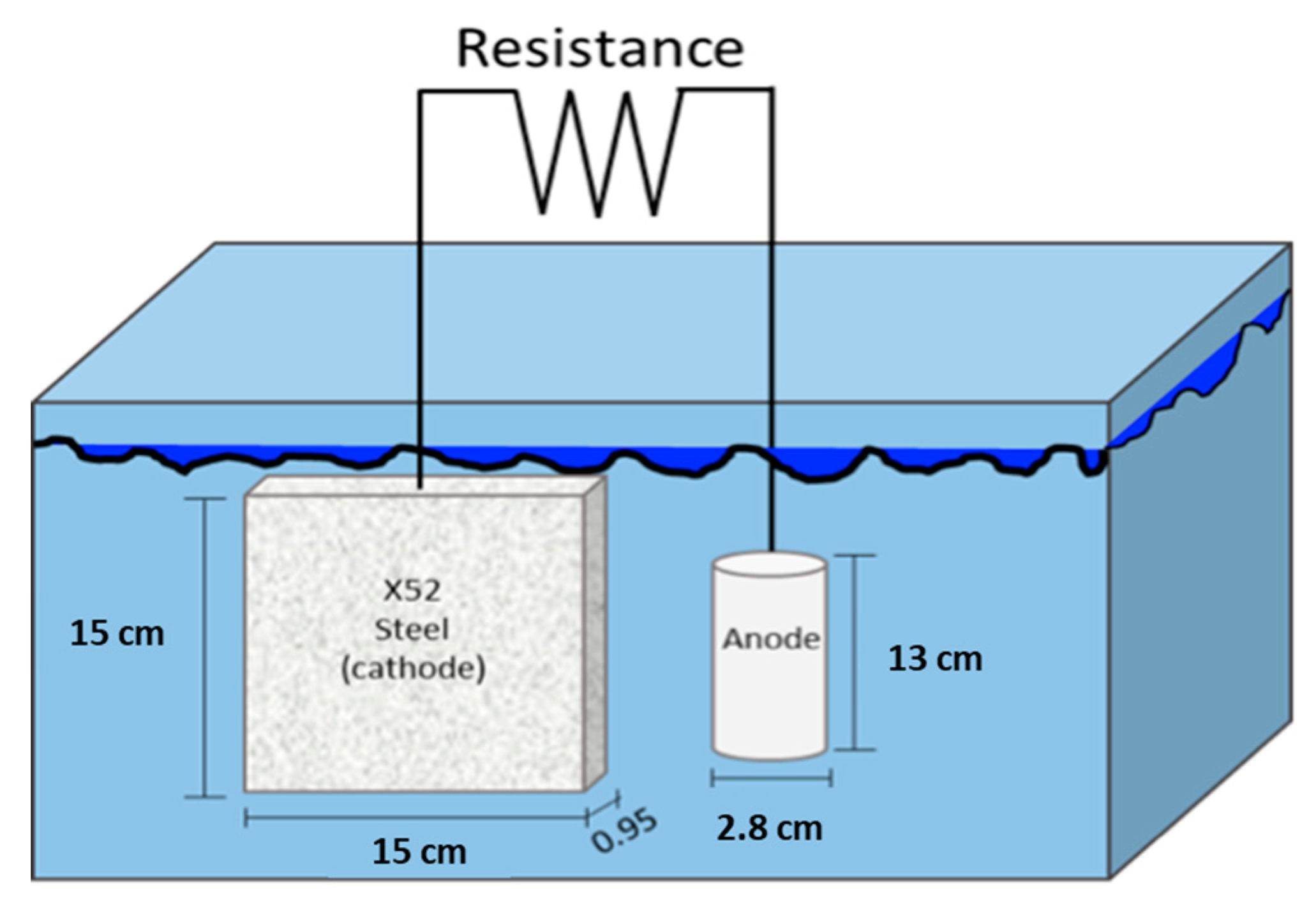
2.4. Cathodic Protection System

For the preparation of the test specimens, the steel plate and the anodes were drilled in the upper edge, in which a metal wire was placed, allowing the establishment of the electrical connection between the X52 steel plate and the anode. Previously, the anodes were mounted on epoxy resin leaving an exposure area of 6.15 cm2. The X52 steel plate was electrically coupled to the anodes, placing a precision resistance of 1 Ω between anode and cathode.
To perform the tests of the cathodic protection, electrochemical cells were designed with the following elements: API X52 steel plates (cathode) with dimensions of 15 × 15 × 0.95 cm3; Mg, Mg-1Nb, and Mg-1Cr anodes with a diameter of 2.8 cm (6.15 cm2 of area) and 13 cm of high (consumable anodes) were used. Figure 3 shows the experimental setup arrangement for the cathodic protection system. Seawater as an electrolyte was taken near the naval base of the Secretariat of the Navy near the capital of the state of Campeche with coordinates of latitude 19°47′42″ N and longitude 90°37′3″ W.
Measurement of voltage drop at both sides of resistance allowed us to calculate the electrical current flow at the circuit applying Ohm’s Law. Seawater was kept in static conditions and was not renewed throughout the experiment.
Once the cell was assembled, the polarized potentials of the cathode, with respect to the saturated calomel electrode (SCE), located at a 1 cm approach to the steel sheet surface, in the function of the exposure time, were monitored. The cathode current density was also monitored with respect to time, calculated from the voltage drop across the resistance and the exposed area of the cathode.

3. Results and Discussion

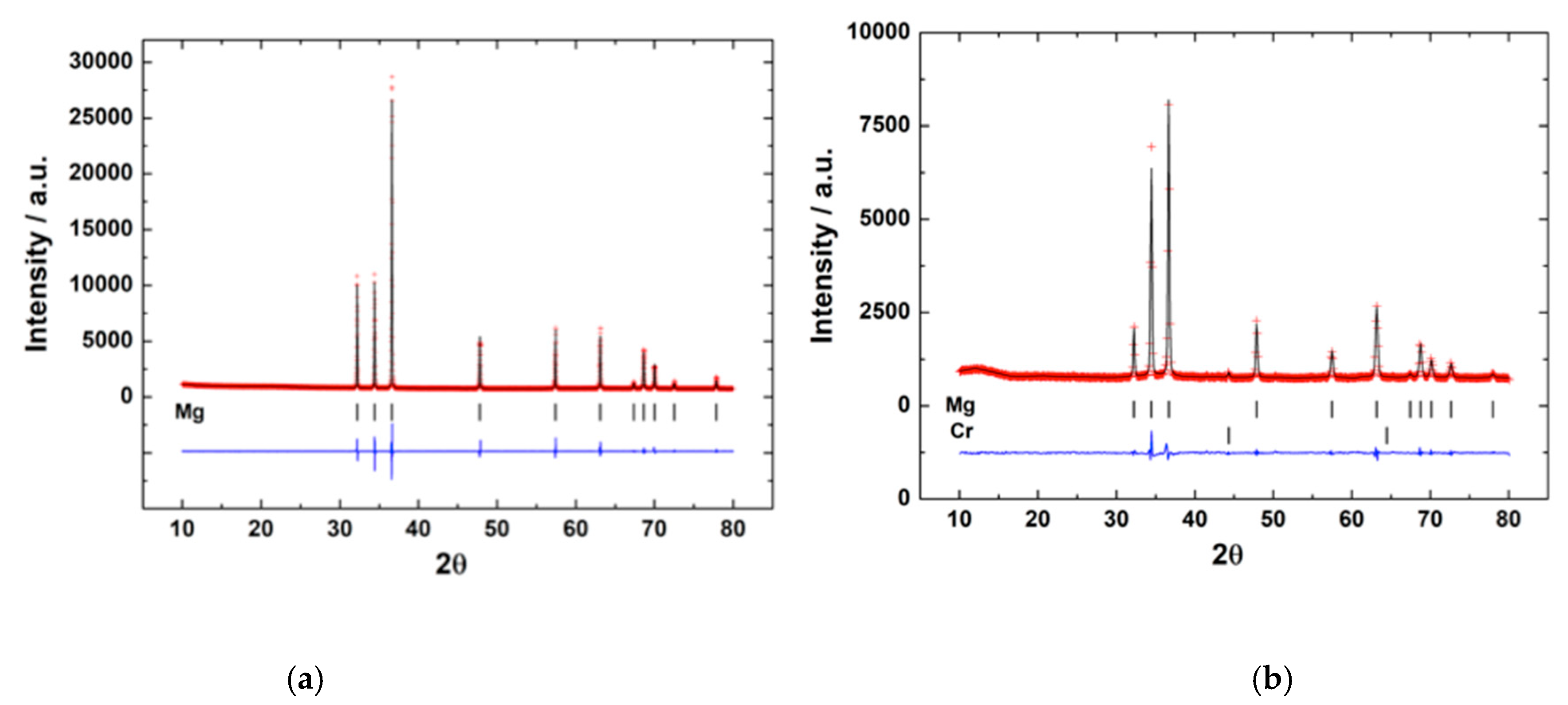
3.1. Microstructure of Mg Anodes

Figure 4 shows a characteristic powder diffraction pattern of pure Mg, as well as the sintered Mg-1Cr sample. The objective of the sintering was only to densify and no reaction was intended. As can be seen in Figure 4a (bottom), after the sintering, no secondary phases were detected. Besides, the amount of Cr or Nb used makes it difficult to detect, at least by X-ray diffraction, if a tiny fraction reacted. Nevertheless, if we consider the phase diagrams of Mg-Cr and Mg-Nb [28,29] no secondary phase was expected.

3.2. Electrochemical Tests

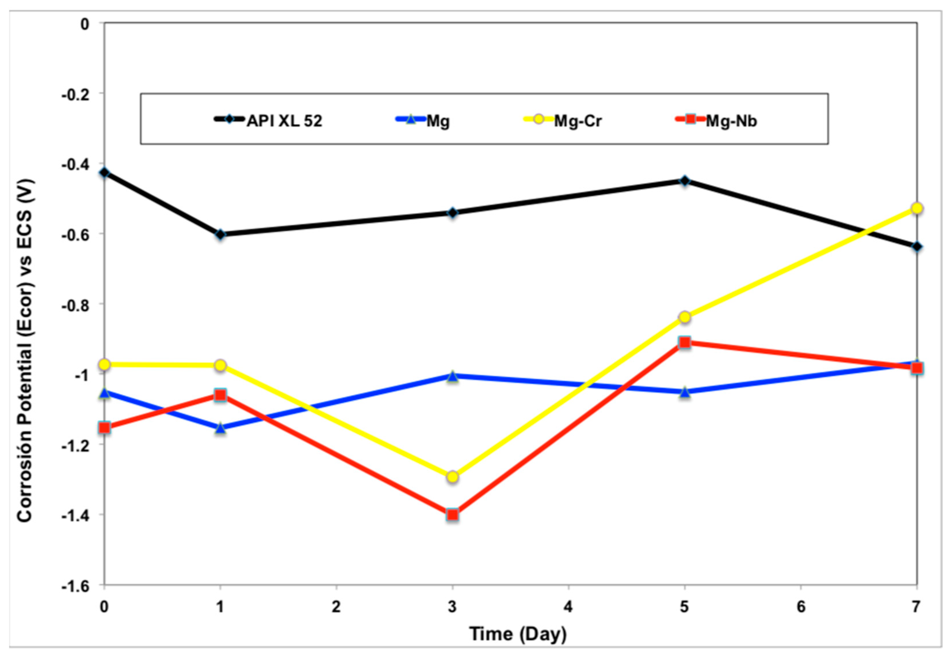
3.2.1. Corrosion Potential (Ecorr)

Figure 5 shows the Ecorr of the X52 steel and the magnesium alloys. For the X52 steel, the Ecorr oscillates between −0.426 (at the beginning) to −0.637 V vs. SCE (after 7 days), which are values close to those reported in similar studies [30]. It is important to say that the plates used were covered with oxides because they remained in prolonged storage. The oxides reported for steels exposed to the weather, by Raman spectroscopy and XRD, were goethite (α-FeOOH), lepidocrocite (γ-FeOOH), and iron oxide (Fe2O3) [31]. When submerging the steel samples in seawater, it is appreciated that they stabilize in a closed range of potential, which indicates that in the interface that forms with the electrolyte, there is no change of composition in the surface oxides.
In the case of pure magnesium, it can be seen that the Ecorr is between −1.150 and −1.0 V. For the Mg-1Cr alloy, the Ecorr starts close to −1.0 V, decreasing to −1.29 V on the third day, and subsequently reaching values of −0.52 V after 7 days. The Mg-1Nb alloy had the most negative values ranging from −1.15 V to −1.40 V on the third day, reaching −0.980 V on the seventh day. The values were close to those obtained in similar studies [32,33].
During the tests, the three anodes (Mg, Mg-1Cr, and Mg-1Nb) showed the evolution of hydrogen, forming bubbles on the surface as shown in Figure 6. Such hydrogen evolution was observed since the beginning of the X52 steel connection to the anodes. Some researchers have been reported this behavior for magnesium and its alloys [34,35,36,37]. Reactions with an intermediate Mg1+ and hydrogen reduction are proposed [38,39] according to the following reaction:
Mg + 2H2O = Mg(OH)2 + H2

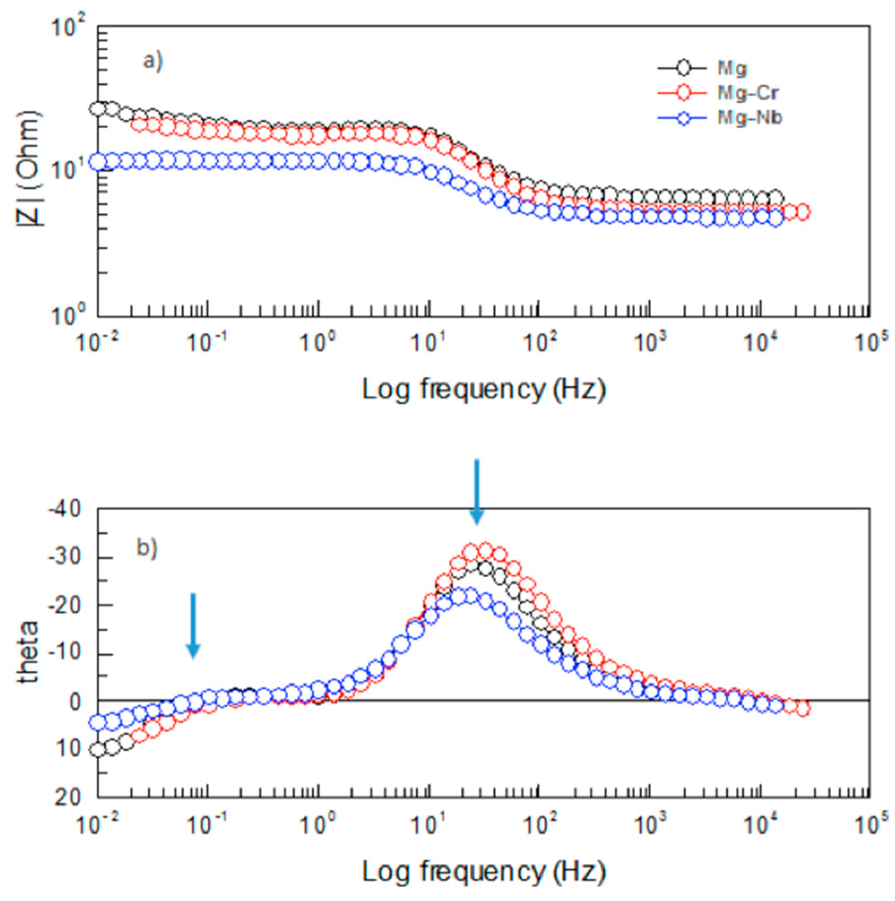
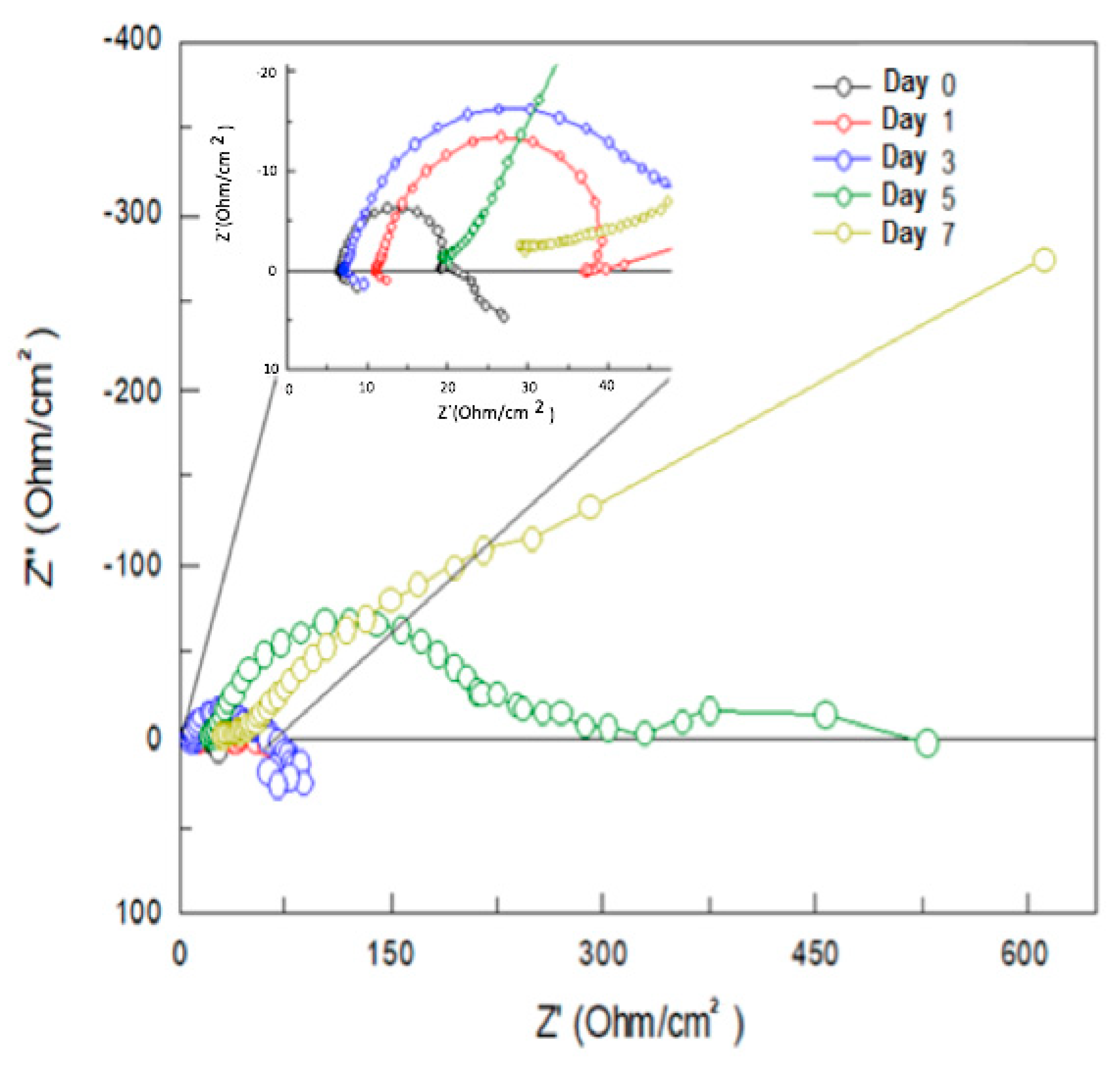
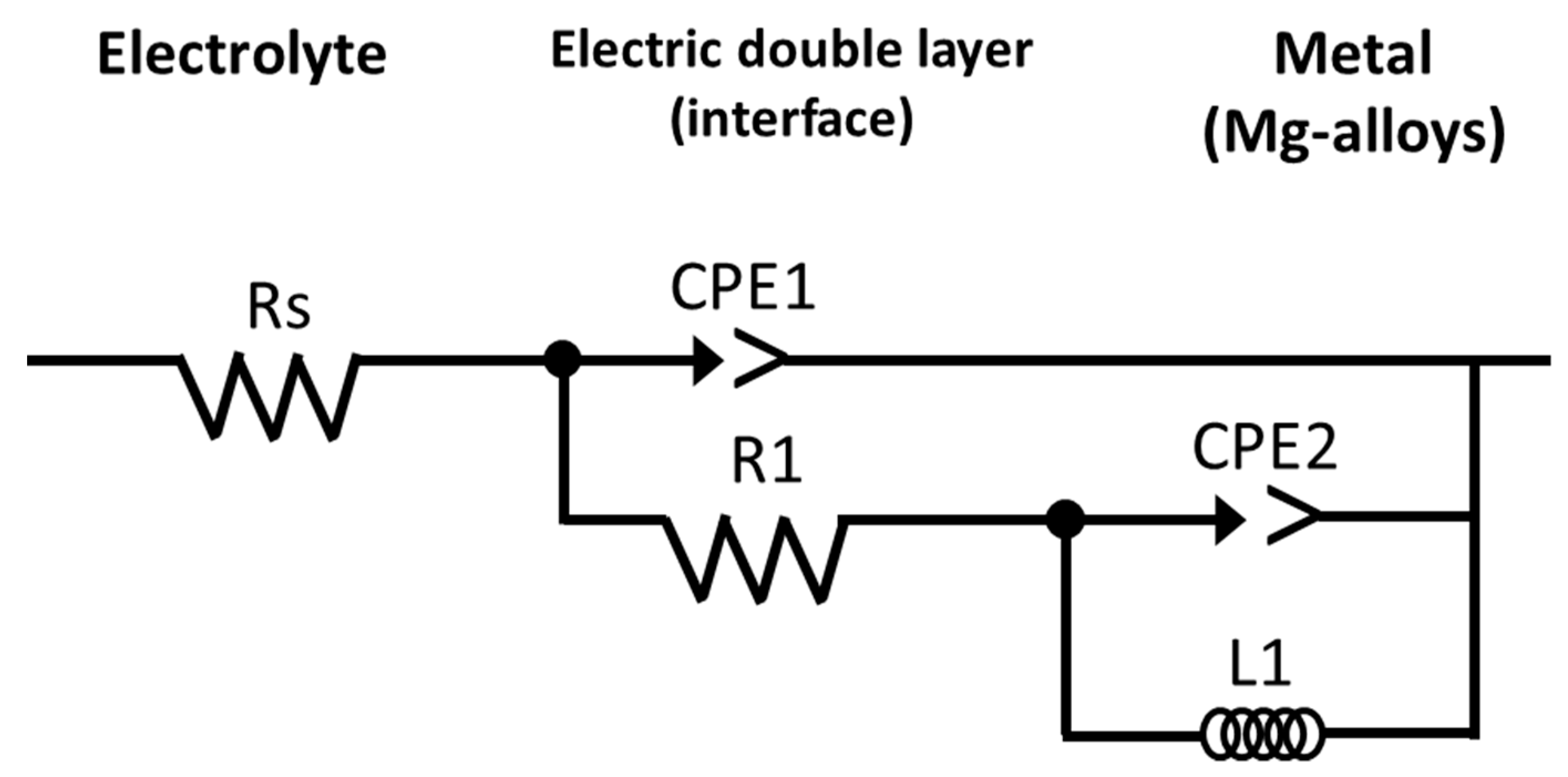
3.2.2. Evaluation of X52 Steel and Mg-Anodes by Electrochemical Impedance Spectroscopy (EIS)

The electrochemical impedance method allows analyzing the behavior of the metal-solution interface, offering a complete overview of the corrosion mechanisms that take place. The analysis of impedance spectra allows simulation of the electrochemical behavior of the system to an equivalent electrical circuit [40].
Figure 7 shows the Nyquist diagrams obtained for the Mg, Mg-Cr, and Mg-Nb anodes immediately after being introduced into natural seawater (Day 0). In this graph, the Y-axis represents the imaginary component of the impedance Z´´ (capacitive behavior), and the X-axis represents the real component Z´ (resistive behavior). The diagrams show two semicircles, one in the region of high frequencies (HF), and another semicircle is defined in the region of low frequencies (LF).
In the literature on the corrosion behavior of magnesium alloys in aqueous solutions, the semicircle in the LF region has always been attributed to the charge transfer reaction of the corrosion process [41] and the diameter (Rct) has been inversely related to the corrosion rate using the Stern-Geary equation [42]. In addition, it was observed that the Nyquist spectra of the three Mg-alloys were similar except in diameter, showing that the corrosion mechanism was the same, but the corrosion rate was different [43].
Since the corrosion rate is inversely related to Rct, the higher the Rct value, the lower the corrosion rate, reflecting unwanted behavior for a sacrificial anode. Therefore, the lower Rct values shown by the Mg-1Nb alloy indicated that corrosion resistance was the lowest, which is favorable for materials being used as an anodic material.
Figure 8 shows the Bode diagrams for the pure-Mg and Mg-1Cr and Mg-1Nb alloys. Figure 8a shows the module (Z) vs. log frequency. Meanwhile, Figure 8b shows the phase angle (θ) vs. log frequency), corresponding to the anode-electrolyte systems studied. The phase angle in the Bode diagrams are indicators of the number of processes that influence the systems studied. Figure 8b shows the presence of two well-defined time constants (formation of two maximums, indicated by an arrow), which could be attributed to the presence of two stages in the corrosion process, which in Nyquist diagrams, means the presence of a capacitive loop at high frequencies (HF) and an inductive loop at low frequencies (LF).
Figure 9, Figure 10 and Figure 11 show the Nyquist diagrams for monitoring of the anodes of Mg, Mg-1Cr, and Mg-1Nb, respectively, for immersion times of 0, 1, 3, 5, and 7 days. The three anodes studied had similar behavior only differentiated by the magnitude of the impedance values.
From the Nyquist diagrams of Figure 9, Figure 10 and Figure 11, a great activity is observed at the beginning (day 0), since it is possible to observe low impedance values at this time. However, it was interesting that the semicircle increasesd its diameter as a function of time, contrary to that desired in a sacrificial anode. This behavior may be due to the formation of a film of stable corrosion products of Mg(OH)2 on the anode surface that provides a decrease in its activity. The result at the beginning of the test was similar to that obtained by Feliu et al. [44] with Mg alloys, only that in its diagrams, we saw a tendency to decrease the dimensions of the semicircles over time and establish the same conditions after 4 days. Similarly, changes in EIS values were observed with the composition of the alloys [45].
The choice of an electrical circuit will depend on the electrochemical characteristics of the material/electrolyte interface. When capacitances are affected by imperfections on the metal surface, (i.e., when they do not exhibit ideal behavior), they are replaced by a constant phase element (CPE).
The equivalent circuit model of the impedance diagram is provided in Figure 12, where Rs represents the resistance of the solution, R1 represents the resistance to load transfer, CPE1 is the capacitance of the electrolyte/metal interface, which is in series with L1 and CPE2, representing the process of hydrogen formation [46]. The constant phase element has been used in the equivalent circuit instead of the pure capacitor to be able to consider the heterogeneities of the surface and obtain a more precise fitting.
Table 2 shows the parameter values that represent the best fit for the experimental data obtained with the equivalent circuit in Figure 12. We observed that Rct tends to increase with immersion time. These variations are related to the increase in the thickness of corrosion products formed on the surface.
Capacitance values (CPE) were in the order of 10−4 F, a value considered as an indicator of a charge transfer process or corrosion process. According to Diaz et al. [47], EIS spectra show a characteristic semicircle of a capacitive process related to the electrochemical double-layer capacitance (Cdl), with values in the order of microfarad attributed to a charge transfer process.

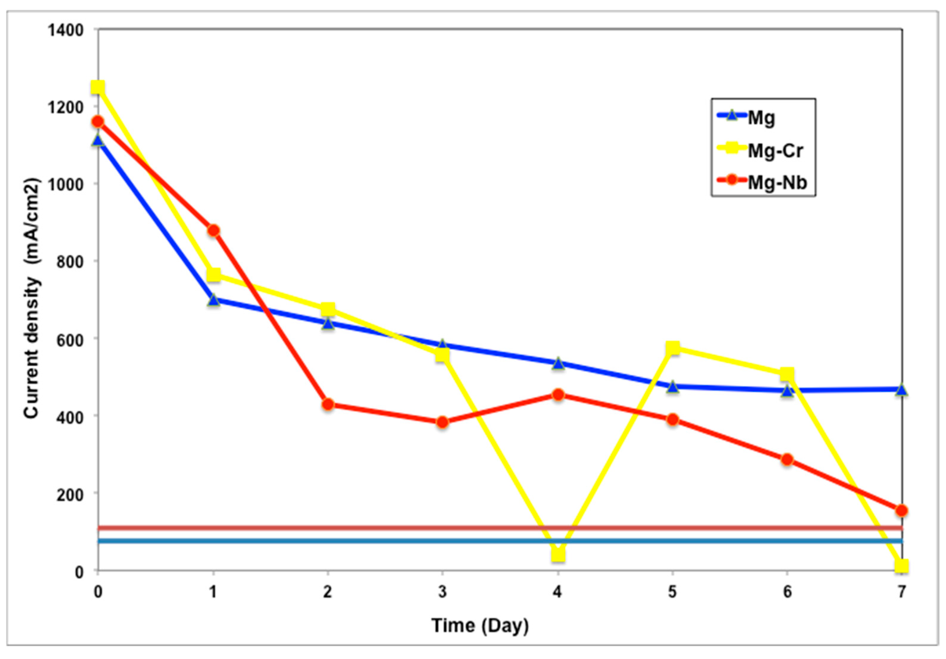
3.2.3. Analysis of the Cathodic Protection System

Figure 13 shows the cathodic polarization potentials (Ec) of X52 steel as a function of immersion time in natural seawater. The Ec of the three systems (Mg/X52, Mg-Cr/X52, and Mg-Nb/X-52) was shifted to cathodic protection values (Ec < −770 mV SCE) and continued decreasing until reaching values between −1.0 and −1.2 V vs. SCE. The Mg/X52 system recorded more negative potential values (<−1.2 V vs. SCE) after 4 days, and the Ec remained very stable after 7 days of exposure time. On the contrary, the less negative values were registered for the Mg-Cr/X52 system (<−1.3 V SCE) on the first day. However, this system was very unstable, and after the first day, the potentials achieved more positive values, reaching values around −0.9 V vs. SCE after 7 days. The Mg-Nb/X52 system showed more stable potentials since the first day, where the recorded values remained between −1.0 and −1.1 V vs. SCE during the seven days of exposure time.
In the three systems in Figure 13, it was observed that the three sacrificial anodes achieve protection of the steel immersed in seawater. However, the case of the Mg/X52 system, with the most negative potential value, may not be adequate as there is a risk of overprotection of steel and hydrogen embrittlement. In the Mg-Cr/X52 systems, under the same conditions, the registered potentials were initially in an overprotection zone and subsequently, the potential was shifted towards more positive values (−1.1 V vs. SCE), which could be attributed to a sample fragmentation and interruption of electron flow and current. In the case of the Mg-Nb/X52 system, the potentials had a more stable behavior and did not exhibit large changes in potential values, attributed to the stability that Nb gives to the alloy.
Figure 14 shows the cathodic current density (i) as a function of the immersion time for the Mg, Mg-1Cr, and Mg-1Nb alloys coupled as the anode to API X52 steel. The graph shows an initial decay of i during the first 24 h of exposure. However, after this period, the trends shown by the three systems were very different from each other. The Mg/X52 system gets stable values of current density after 120 h, reaching stable values around 480 mA/m2. For the Mg-Cr/X52 system, current fluctuations occurred after three days of exposure time, reaching values close to zero after 7 days of exposure, which could be due to the loss of material during the test producing changes in current. This could be attributed to the fact that the anode system fragments and the flow of electrons are limited because the system is unable to provide the necessary protection current density. In the curve of the Mg-Nb/X52 system, the current density showed a relatively abrupt initial decrease, and subsequently, a slower decay until reaching a more stable value. However, the current density continued decreasing after 5 days until reaching values around 150 mA/m2. This behavior is attributed to properties that Nb provides in the Mg-alloy, which makes a more compact anode that limits the loss of material and maintains the constant flow of electrons. The Mg-Nb alloy shows better characteristics as a galvanic anode because the potential maintains between −850 mV and −100 mV, as well as an electric current density higher than 110 mA/m2 for initial polarization (brown line) and 75 mA/m2 (grey line) for final polarization as established by the Mexican standard for cathodic protection criteria design [48].

4. Conclusions

Galvanic anodes of Mg, Mg-1Cr, and Mg-1Nb were fabricated by mixing and sintering powders at a temperature of 500 °C. Performance on the cathodic protection of X52 steel using these anodes exposed to seawater was carried out. During the tests, the three anodes (Mg, Mg-1Cr, and Mg-1Nb) show the evolution of hydrogen, forming bubbles on the surface. Results of EIS give lower Rct values for the Mg-1Nb anode, indicating lower corrosion resistance, which is favorable for materials being used as an anodic material. It is observed that Rct tends to increase with immersion time. These variations are related to the increase in the thickness of corrosion products formed on the surface. Measurements of cathodic potential (Ec) and current density (i) in the function of time were performed. The results of potential indicated that the X52 steel of the three systems remained in the protection zone. The Mg/X52 system reaches stable values of potential and current density after 120 h, reaching stable values around −1.2 V (SCE) and 480 mA/m2, respectively. For the Mg-1Cr/X52 system, current fluctuations occurred after three days of exposure time, reaching values close to zero after 7 days of exposure, which could be due to the loss of connection, producing errors in the measurement of current discharges. For the Mg-1Nb/X52 system, the current density showed a relatively abrupt initial decrease and subsequently a slower decay. However, the current density continues decreasing after 7 days until it reaches values around 150 mA/m2. This behavior is attributed to properties that Nb provides in the Mg-alloy, which makes a more compact anode that in turn limits the loss of material and maintains the constant flow of electrons. The Mg/X52 system recorded the most negative potential values, which can be attributed to a greater magnitude of drained current density and a better distribution of the cathodic protection current but remains in the overprotection zone. However, the Mg-1Nb/X52 systems could have a better result because the potential obtained by this system was constant throughout the 7 days.

Author Contributions

Conceptualization and writing—original draft preparation, J.A.S.-M. and T.P.-L.; methodology and Formal analysis, R.L.-A., E.A.J.-A., and J.T.P.-Q.; validation and formal analysis, A.C. All authors have read and agreed to the published version of the manuscript.

Funding

This research was funded by CONACYT, grant number CB-2009-01-129934.

Data Availability Statement

The data presented in this study are available in Master Thesis “Evaluación de un sistema de protección catódica utilizando Mg y aleaciones Mg-Cr y Mg-Nb como ánodos de sacrificio en la protección de aceros API X52 y API X65 en agua de mar”, Judith Amairany Sanmiguel May; December 2017; Universidad Autónoma de Campeche, assigned an electronic record is in process.

Acknowledgments

The authors express their gratitude to CONACYT for the financial support granted for the development of this research through the project CB-2009-01-129934.

Conflicts of Interest

The authors declare no conflict of interest.

References

  1. Feng, Y.; Liu, L.; Yin, L.; Wang, R.; Li, X. Effect of lanthanum on microstructure and electrochemical corrosion behavior of Mg-6Al-5Pb alloy. Trans. Nonferrous Met. Soc. China 2015, 25, 2623–2631. [Google Scholar]
  2. Wang, N.; Wang, R.; Peng, C.; Feng, Y.; Chen, B. Effect of hot rolling and subsequent annealing on electrochemical discharge behavior of AP65 magnesium alloy as anode for seawater activated battery. Corr. Sci. 2012, 64, 17–27. [Google Scholar] [CrossRef]
  3. Wang, N.; Wang, R.; Peng, C.; Feng, Y. Enhancement of the discharge performance of AP65 magnesium alloy anodes by hot extrusion. Corros. Sci. 2014, 81, 85–95. [Google Scholar] [CrossRef]
  4. Jugović, B.; Gvozdenović, M.; Stevanović, J.; Trišović, T.; Grgur, B. Corrosion behavior of magnesium, aluminum and zinc as anodic materials in chloride based electrolytes for use in primary and secondary electrochemical power sources. Mater. Des. 2009, 30, 3291–3294. [Google Scholar] [CrossRef]
  5. Çiçek, B.; Sun, Y. A study on the mechanical and corrosion properties of lead added magnesium alloys. Mater. Des. 2012, 37, 369–372. [Google Scholar] [CrossRef]
  6. Wang, L.; Zhang, B.; Shinohara, T. Corrosion behavior of AZ91 magnesium alloy in dilute NaCl solutions. Mater. Des. 2010, 31, 857–863. [Google Scholar] [CrossRef]
  7. Boby, A.; Srinivasan, A.; Pillai, U.T.S.; Pai, B.C. Mechanical characterization and corrosion behavior of newly designed Sn and Y added AZ91 alloy. Mater. Des. 2015, 88, 871–879. [Google Scholar] [CrossRef]
  8. Shi, Y.; Peng Ch Feng, Y.; Wang, R.; Wang, N. Microstructure and electrochemical corrosion behavior of extruded Mg–Al–Pb–La alloy as anode for seawater-activated battery. Mater. Des. 2017, 124, 24–33. [Google Scholar] [CrossRef] [Green Version]
  9. Zhang, T.; Meng, G.; Shao, Y.; Cui, Z.; Wang, F. Corrosion of hot extrusion AZ91 magnesium alloy. Part II: Effect of rare earth element neodymium (Nd) on the corrosion behavior of extruded alloy. Corros. Sci. 2011, 53, 2934–2942. [Google Scholar] [CrossRef]
  10. Meng, J.; Sun, W.; Tian, Z.; Qiu, X.; Zhang, D. Corrosion performance of magnesium (Mg) alloys containing rare-earth (RE) elements. In Corrosion Prevention of Magnesium Alloys; Woodhead Publishing: Cambridge, UK, 2013; pp. 38–60. [Google Scholar]
  11. Zakowski, K. Studying the effectiveness of a modernized cathodic protection system for an offshore platform. Anti Corros. Methods Mater. 2011, 58, 167–172. [Google Scholar] [CrossRef]
  12. Narozny, M.; Zakowski, K.; Darowicki, K. Method of sacrificial anode transistor driving in cathodic protection system. Corros. Sci. 2014, 88, 275–279. [Google Scholar] [CrossRef]
  13. Wang, R.C.; Li, Q.; Wang, N.G.; Peng, C.Q.; Feng, Y. Effect of lithium on the discharge and corrosion behavior of Mg-3 wt.% Al-alloy as the anode for seawater activated battery. J. Mater. Eng. Perform. 2018, 27, 6552–6563. [Google Scholar] [CrossRef]
  14. Wang, L.; Li, P.; He, L. Effect of adding different contents of mercury to magnesium on discharge and corrosion performances of magnesium anode sheet. Russ. J. Electrochem. 2011, 47, 900–907. [Google Scholar] [CrossRef]
  15. Esmaily, M.; Svensson, J.E.; Fajardo, S.; Birbilis, N.; Frankel, G.S.; Virtanen, S.; Arrabal, R.; Thomas, S.; Johansson, L.G. Fundamentals and advances in magnesium alloy corrosion. Prog. Mater. Sci. 2017, 89, 92–193. [Google Scholar] [CrossRef]
  16. Banjade, D.R. Galvanic Corrosion of Magnesium Coupled to Steel at High Cathode-to-Anode Area Ratios. Master’s Thesis, Brigham Young University, Provo, UT, USA, 2015. [Google Scholar]
  17. Tang, D.; Du, Y.; Li, X.; Liang, Y.; Lu, M. Effect of alternating current on the performance of magnesium sacrificial anode. Mater. Des. 2016, 9, 133–145. [Google Scholar] [CrossRef]
  18. Kalisvaart, P.; Luber, E.; Fritzsche, H.; Mitlin, D. Effect of alloying magnesium with chromium and vanadium on hydrogenation kinetics studied with neutron reflectometry. Chem. Comm. 2011, 47, 4294–4296. [Google Scholar] [CrossRef] [Green Version]
  19. Mosaner, P.; Bazzanella, N.; Bonelli, M.; Checchetto, M.; Miotello, A. Mg:Nb films produced by pulsed laser deposition for hydrogen storage. Mater. Sci. Eng. B 2004, 108, 33–37. [Google Scholar] [CrossRef]
  20. De Castro, J.F.R.; Santos, S.F.; Costa, A.L.M.; Yavari, A.R.; Botta, W.J.F.; Ishikawa, T.T. Structural characterization and dehydrogenation behavior of Mg–5 at.% Nb nano-composite processed by reactive milling. J. Alloys Compd. 2004, 376, 251–256. [Google Scholar] [CrossRef]
  21. Shanthi, M.; Jayaramanavar, P.; Vyas, V.; Seenivasan, D.V.S.; Gupta, M. Effect of niobium particulate addition on the microstructure and mechanical properties of pure magnesium. J. Alloys Compd. 2012, 513, 202–207. [Google Scholar] [CrossRef]
  22. Staišiūnas, L.; Leinartas, K.; Samulevičienė, M.; Miečinskas, P.; Grigucevičienė, A.; Juškėnas, R.; Juzeliūnas, E. Electrochemical and structural characterization of sputter-deposited Mg–Nb and Mg–Nb–Al–Zn alloy films. J Solid State Electroch. 2013, 17, 1649–1656. [Google Scholar] [CrossRef]
  23. Shang, C.X.; Bououdina, M.; Guo, Z.X. Structural stability of mechanically alloyed (Mg+10Nb) and (MgH2+10Nb) powder mixtures. J. Alloys Compd. 2003, 349, 217–223. [Google Scholar] [CrossRef]
  24. Martinez-Garcia, A.; Navarro-Mtz, A.K.; Reguera, E.; Valera-Zaragoza, M.; Morales-Serna, J.A.; Juarez-Arellano, E.A. Fabrication of ball-milled MgO-Mg(OH)2-hydromagnesite composites and evaluation as an air-stable hydrogen storage material. Int. J. Hydrogen Energy 2020, 45, 12949–12960. [Google Scholar] [CrossRef]
  25. Abidin, N.I.Z.; Atrens, A.D.; Martin, D.; Atrens, A. Corrosion of high purity Mg, Mg2Zn0.2Mn, ZE41 and AZ91 in Hank’s solution at 37 °C. Corros. Sci. 2011, 53, 3542–3556. [Google Scholar] [CrossRef]
  26. Song, G.L.; Atrens, A. Understanding magnesium corrosion—A framework for improved alloy performance. Adv. Eng. Mater. 2003, 5, 837–858. [Google Scholar] [CrossRef]
  27. Shi, Z.; Liu, M.; Atrens, A. Measurement of the corrosion rate of magnesium alloys using Tafel extrapolation. Corros. Sci. 2010, 52, 579–588. [Google Scholar] [CrossRef]
  28. Likhanova, N.V.; Nava, N.; Olivares-Xometl, O.; Domínguez-Aguilar, M.A.; Arellanes-Lozada, P.; Lijanova, I.V.; Arriola-Morales, J.; Lartundo-Rojas, L. Corrosion evaluation of pipeline steel API 5L X52 in partially deaerated produced water with high chloride content. Int. J. Electrochem. Sci. 2018, 13, 7949–7967. [Google Scholar] [CrossRef]
  29. Mezbahul-Islam, M.; Mostafa, A.; Medraj, M. Essential Magnesium Alloys Binary Phase Diagrams and Their Thermochemical Data. J. Mater. 2014, 2014, 1–33. [Google Scholar] [CrossRef] [Green Version]
  30. Pelton, A.D.; Degterov, S.A.; Eriksson, G.; Robelin, C.; Dessureault, Y. The modified quasichemical model I—Binary Journal of Materials solutions. Metall. Mater. Trans. B 2000, 31, 651–659. [Google Scholar] [CrossRef]
  31. Altobelli, R.; Costa, I.; Faria, D.L.A.D. Characterization of corrosion products formed on steels in the first months of atmospheric exposure. Mater. Res. 2003, 6, 403–408. [Google Scholar]
  32. Qu, Q.; Wang, L.; Li, L.; He, Y.; Yang, M.; Ding, Z. Effect of the fungus, Aspergillus Niger, on the corrosion behaviour of AZ31B magnesium alloy in artificial seawater. Corros. Sci. 2015, 98, 249–259. [Google Scholar] [CrossRef]
  33. Wei, D.; Wang, J.; Wang, H.; Liu, Y.; Lib, S.; Li, D. Anti-corrosion behaviour of super wetting structured surfaces on Mg-9Al-1Zn magnesium alloy. Appl. Surf. Sci. 2019, 483, 1017–1026. [Google Scholar] [CrossRef]
  34. Williams, G.; Birbilis, N.; McMurray, H.N. The source of hydrogen evolved from a magnesium anode. Electrochem. Commun. 2013, 36, 1–5. [Google Scholar] [CrossRef]
  35. Frankel, G.; Samaniego, A.; Birbilis, N. Evolution of hydrogen at dissolving magnesium surfaces. Corros. Sci. 2013, 70, 104–111. [Google Scholar] [CrossRef] [Green Version]
  36. Gabbardo, A.; Viswanathan, G.; Frankel, G. Application of 2D pit growth method to Mg thin films: Part II. Salt film and hydrogen evolution. J. Electrochem. Soc. 2019, 166, C3266–C3274. [Google Scholar] [CrossRef]
  37. Fajardo, S.; Bosch, J.; Frankel, G. Anomalous hydrogen evolution on AZ31, AZ61 and AZ91 magnesium alloys in unbuffered sodium chloride solution. Corros. Sci. 2019, 146, 163–171. [Google Scholar] [CrossRef]
  38. Frankel, G.; Fajardo, S.; Lynch, B.M. Introductory lecture on corrosion chemistry: A focus on anodic hydrogen evolution on Al and Mg. Faraday Discuss. 2015, 180, 11–33. [Google Scholar] [CrossRef]
  39. Chen, Y.K.; An, Z.; Chen, M. Competition mechanism study of Mg+H2O and MgO+H2O reaction. In Proceedings of the 6th Asia Conference on Mechanical and Materials Engineering (ACMME 2018) IOP Conference Series: Materials Science and Engineering, Seoul, Korea, 15–18 June 2018; pp. 1–5. [Google Scholar]
  40. He, B.; Lu, C.; Han, P.; Bai, X. Short-term electrochemical corrosion behavior of pipeline steel. Eng. Fail. Anal. 2016, 59, 410–418. [Google Scholar] [CrossRef]
  41. Guadarrama-Muñoz, F.; Mendoza-Flores, J.; Duran-Romero, R.; Genesca, J. Electrochemical study on magnesium anodes in NaCl and CaSO4–Mg(OH)2 aqueous solutions. Electrochim. Acta. 2006, 51, 1820–1830. [Google Scholar] [CrossRef]
  42. Stern, M.; Geary, A.L. Electrochemical polarization 1. A theoretical analysis of the shape of polarization curves. Int. J. Electrochem. Soc. 1957, 104, 56–63. [Google Scholar] [CrossRef]
  43. Kun, Y.U.; Huang, Q.; Jun, Z.; DAI, Y.L. Electrochemical properties of magnesium alloy anodes discharged in seawater. Trans. Nonferrous Met. Soc. China 2012, 22, 2184–2190. [Google Scholar]
  44. Feliú, S.; Samaniego, A.; Bermudez, E.; Abdelsam El-Hadad, A.; Llorente, I.; Galván, J.C. Effect of native oxide film on commercial magnesium alloys substrates and carbonate conversion coating growth and corrosion resistance. Materials 2014, 7, 2534–2560. [Google Scholar] [CrossRef] [PubMed] [Green Version]
  45. Feliú, S.; García-Galván, F.R.; Llorente, I.; Diaz, L.; Simancas, J. Influence of hydrogen bubbles adhering to the exposed surface on the corrosion rate of magnesium alloys AZ31 and AZ61 in sodium chloride solution. Mater. Corros. 2017, 68, 651–663. [Google Scholar] [CrossRef]
  46. Wen, L.; Yu, K.; Xiong, H.; Dai, Y.; Yang, S.; Qiao, X.; Teng, F.; Fan, S. Composition optimization and electrochemical properties of Mg-Al-Pb-(Zn) alloys as anodes for seawater activated battery. Electrochim. Acta 2016, 194, 40–51. [Google Scholar] [CrossRef]
  47. Diaz, L.; Garcia, F.R.; Llorente, I.; Jimenez, A.; Galvan, J.C.; Feliu, S. Effect of heat treatment of magnesium alloy substrates on corrosion resistance of a hybrid organic–inorganic sol–gel film. RSC Adv. 2015, 5, 105735–105746. [Google Scholar] [CrossRef]
  48. NRF-047-PEMEX-2014-Diseño, instalación y mantenimiento de los sistemas de protección catódica (Design, Installation and Maintenance of Cathodic Protection Systems, Reference Standard). Available online: https://www.academia.edu/36140282/NRF_047_PEMEX_2014_Anodos_y_tierras_fisicas (accessed on 5 November 2020).
Figure 1. Typical microstructure of X52 steel obtained by optical microscopy.
Metals 11 00406 g001
Figure 2. Anode manufacturing process, (a) powder compaction, (b) green anodes obtained, (c) sintering of anodes at 500 °C, (d) sintered anode, (e) anode encapsulation.
Metals 11 00406 g002
Figure 3. Experimental setup for the tests of cathodic protection.
Metals 11 00406 g003
Figure 4. (a). Le Bail fits of the diffractogram of pure magnesium after thermal treatment. (b). Le Bail fits of the diffractogram of Mg-1Cr after thermal treatment.
Metals 11 00406 g004
Figure 5. Corrosion potential (Ecorr) for X52 steel, pure-Mg, Mg-1Cr, and Mg-1Nb.
Metals 11 00406 g005
Figure 6. Hydrogen evolution at anodes electrically connected to X52 steel in seawater.
Metals 11 00406 g006
Figure 7. Nyquist diagrams of the anode-electrolyte systems immediately after being introduced into seawater.
Metals 11 00406 g007
Figure 8. Bode diagrams of anode-electrolyte systems immediately after being introduced into seawater.
Metals 11 00406 g008
Figure 9. Nyquist diagrams for pure-Mg anode for 0, 1, 3, 5, and 7 days of immersion in seawater.
Metals 11 00406 g009
Figure 10. Nyquist diagrams for Mg-1Cr anode for 0, 1, 3, 5, and 7 days of immersion in seawater.
Metals 11 00406 g010
Figure 11. Nyquist diagrams for Mg-1Nb anode for 0, 1, 3, 5, and 7 days of immersion in seawater.
Metals 11 00406 g011
Figure 12. Equivalent electric circuit used to fit the EIS spectra of the Mg-anodes immersed in seawater.
Metals 11 00406 g012
Figure 13. Cathodic polarization potential for the X52 steel in the function of immersion time in seawater for the three anodes.
Metals 11 00406 g013
Figure 14. Current density (i) in the function of the immersion time in seawater for X52 steel cathodically polarized for the three anodes.
Metals 11 00406 g014
Table 1. Chemical composition of the X52 steel (wt. %).
CMnSiPSCuCrNiNbVTiAlFe
0.081.050.260.0190.0030.0190.020.020.0410.0540.0020.038Bal.
Table 2. Electrochemical parameters obtained from EIS tests.
AnodeImmersion Time (Days)Rs
(Ohms.cm2)
R1
(Ohms.cm2)
CPE (Farads)
Mg06.4513.240.000793
Mg-Cr05.2211.150.000031
Mg-Nb06.4513.240.001155
Mg111.117.970.000204
Mg-Cr116.3839.960.000124
Mg-Nb15.2316.010.000256
Mg37.3843.870.000814
Mg-Cr348.84105.50.001627
Mg-Nb332.4747.190.005315
Mg520.21233.80.000586
Mg-Cr5126.317900.005412
Mg-Nb513.45331.40.013894
Mg732.93220.50.013752
Mg-Cr7125858.40.005583
Mg-Nb717.939200.019321
Publisher’s Note: MDPI stays neutral with regard to jurisdictional claims in published maps and institutional affiliations.

