
Analysis of Additional Load and Fatigue Life of Preloaded Bolts in a Flange Joint Considering a Bolt Bending Load


Abstract
:1. Introduction
2. Analytical Evaluation of a Bolted Joint
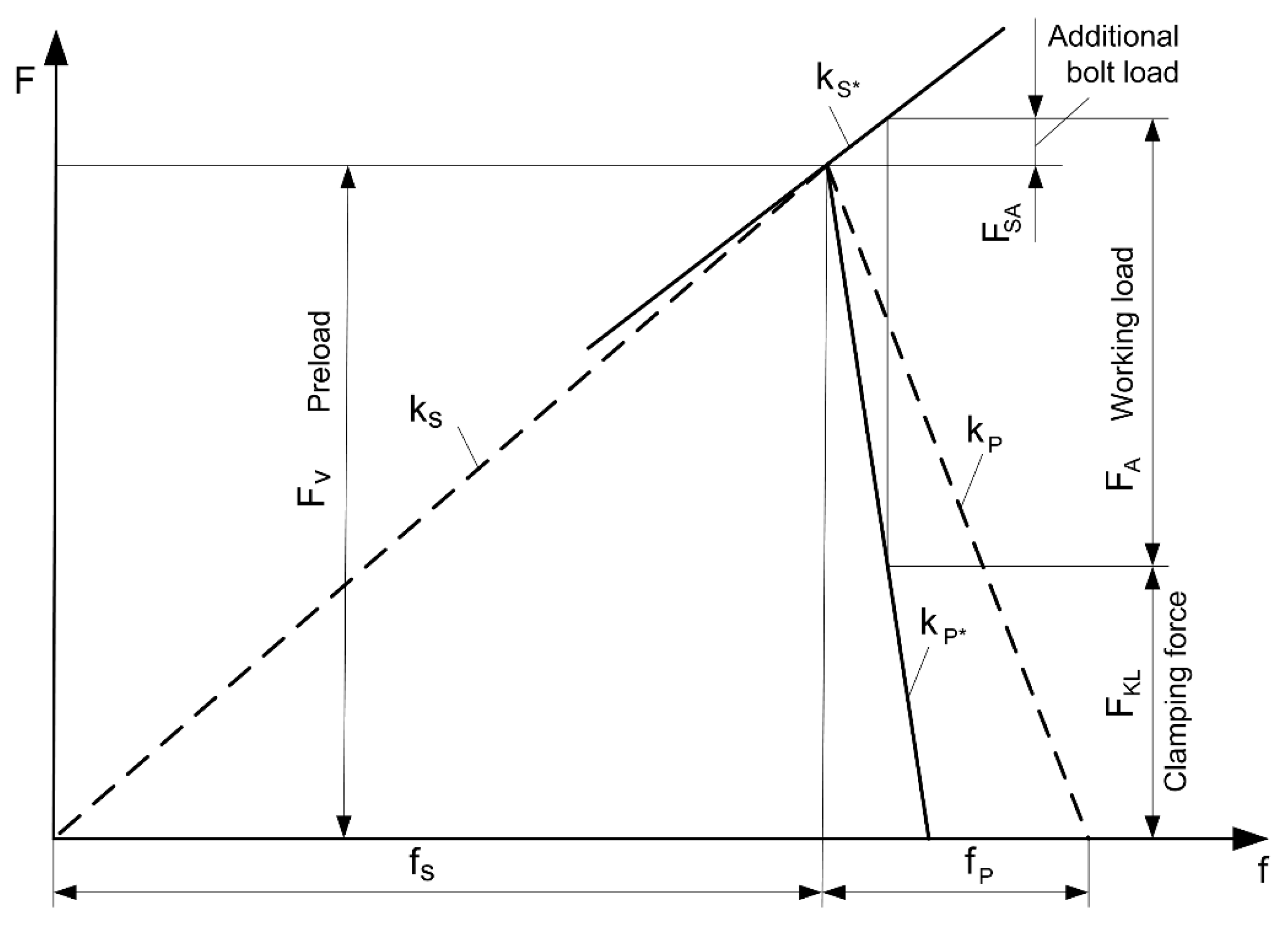
2.1. Forces in a Preloaded Bolted Joint
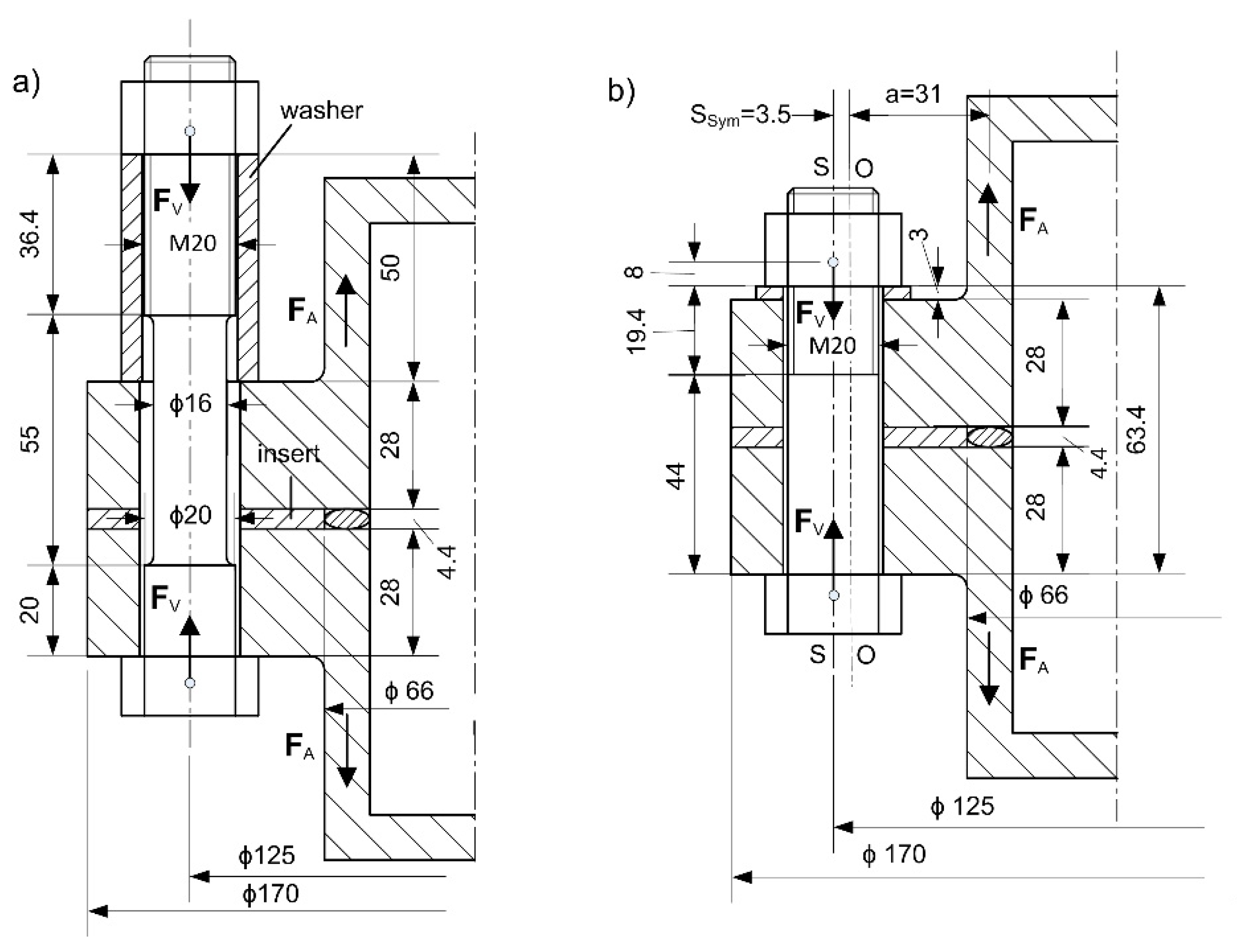
2.2. Shape and Dimensions of a Bolted Flange Joint
2.3. Resilience of Bolt and Clamping Parts
2.4. Results of the Analytical Calculation
3. Numerical Analysis
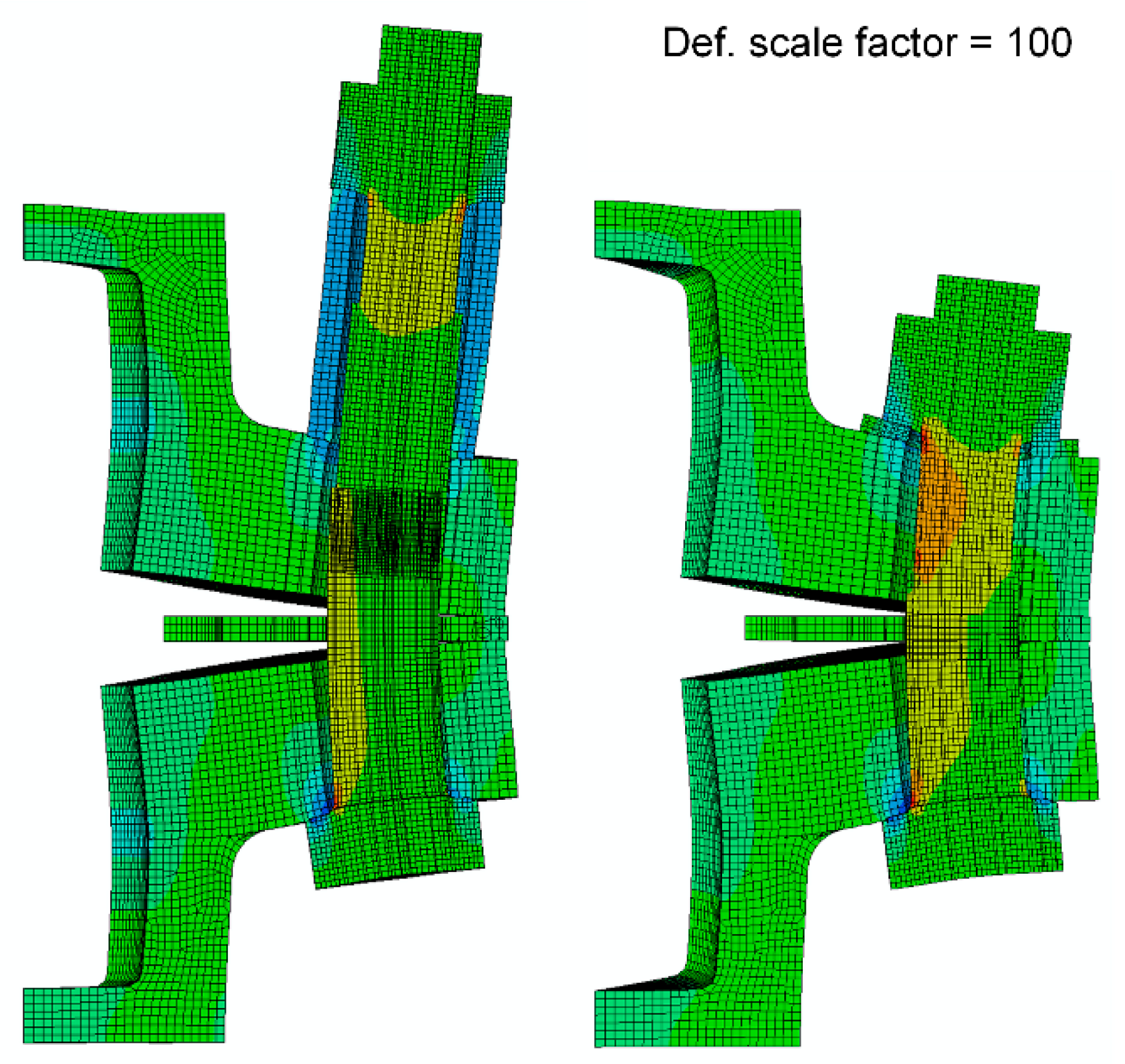
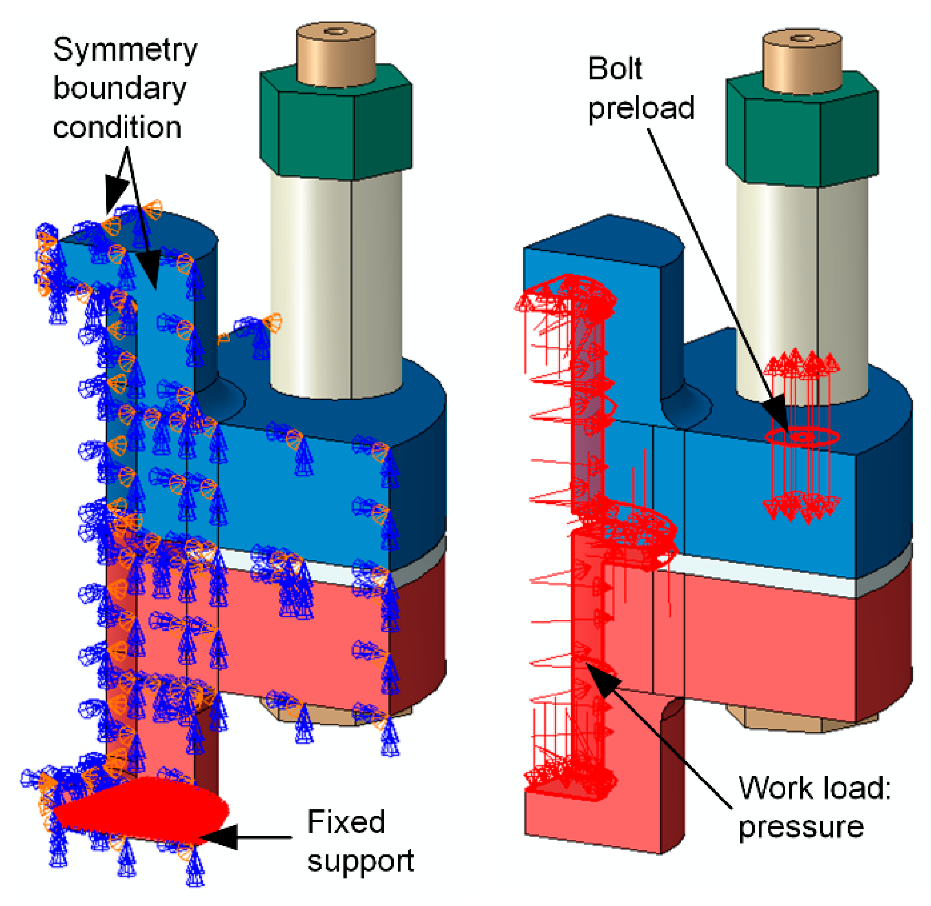
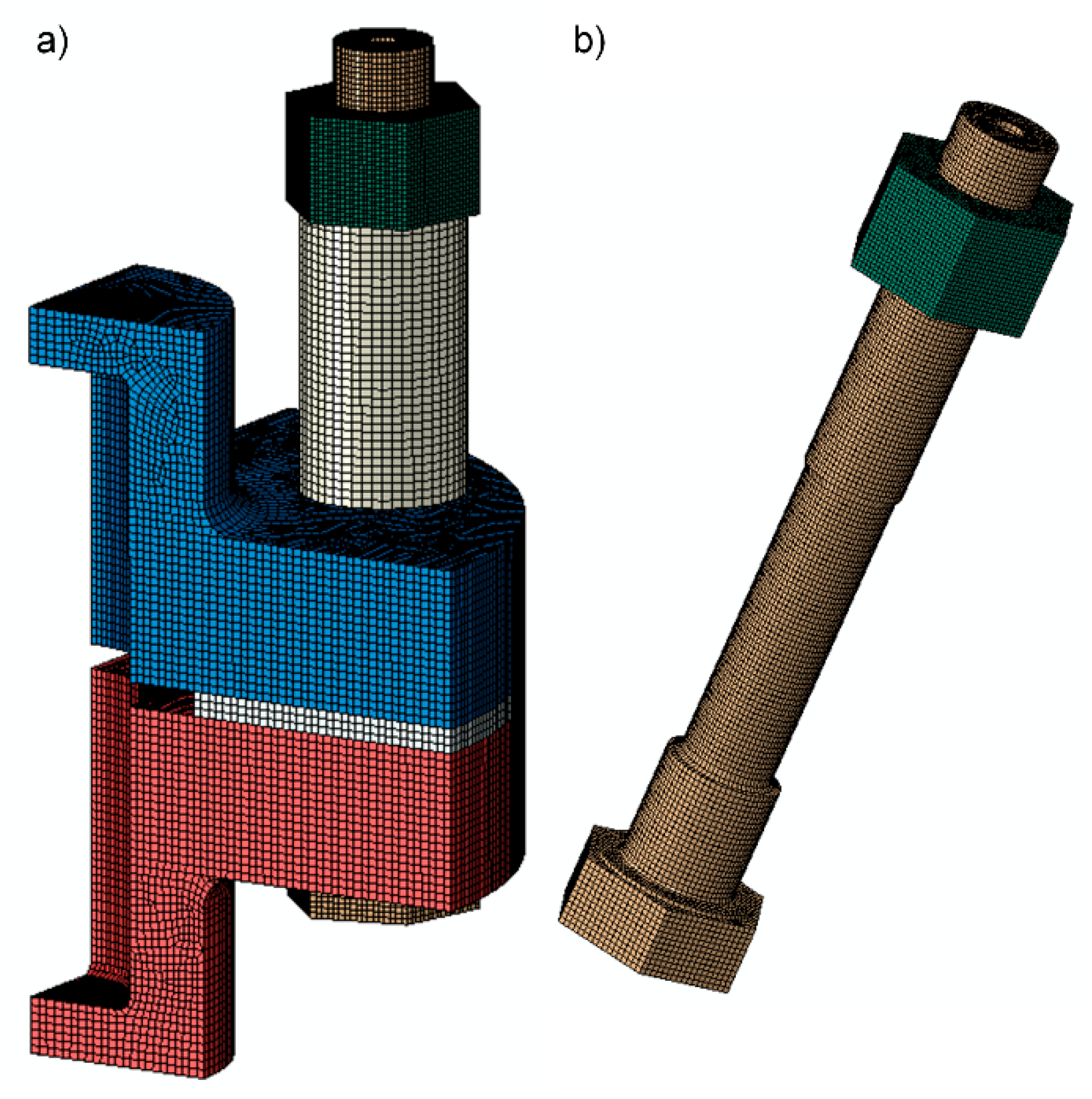
3.1. Finite Elements Model
3.2. Results of the Finite Element Analyses
- change of axial force in the bolt due to the working load,
- distribution of the axial stress in the bolt shank (calculation of the bending ratio and the axial stress range) and
- the influence of the size and type of elements on results.
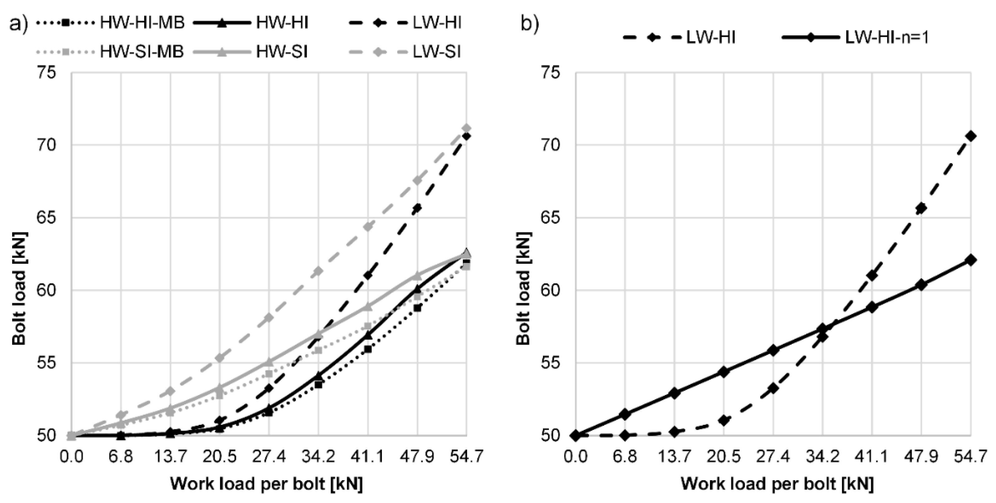
3.2.1. Change of Axial Force in the Bolt Due to the Working Load
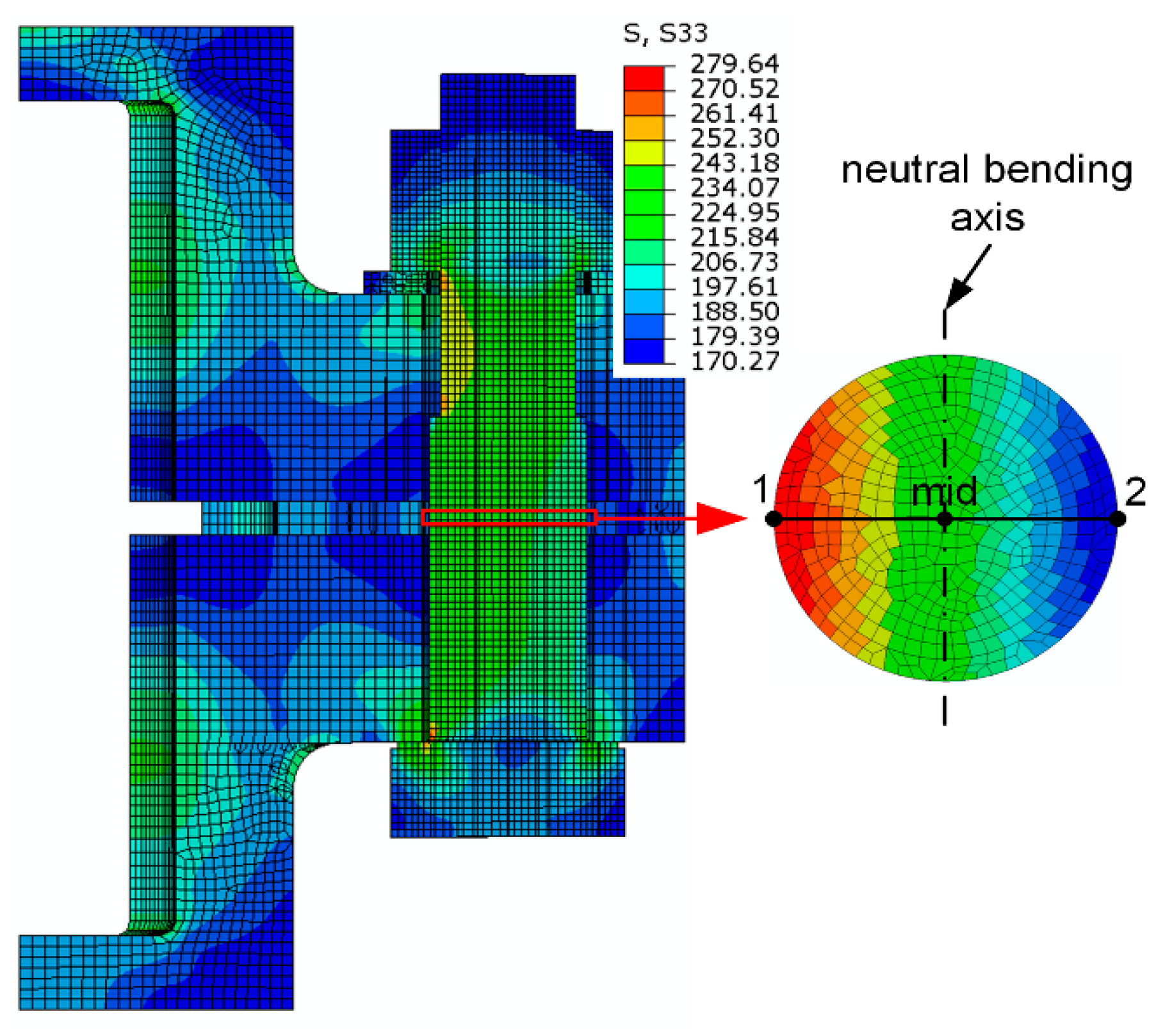
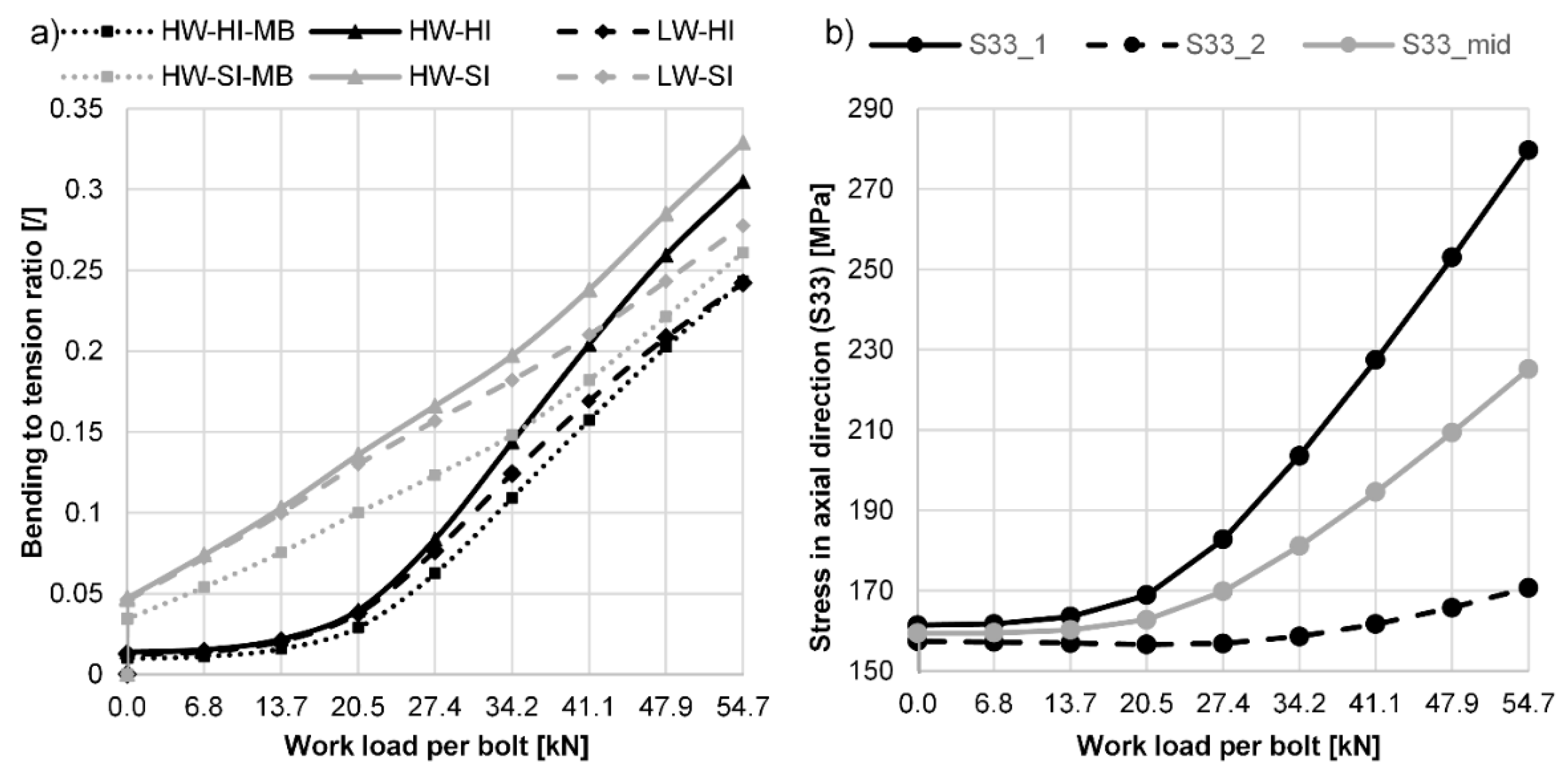
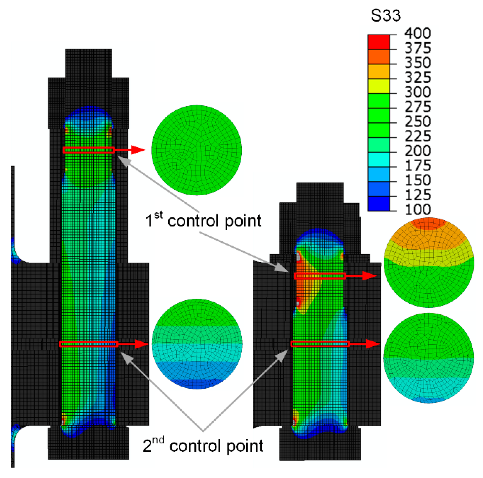
3.2.2. Distribution of Axial Stress in the Bolt Shank
3.2.3. The Influence of the Size and Type of Elements on Results
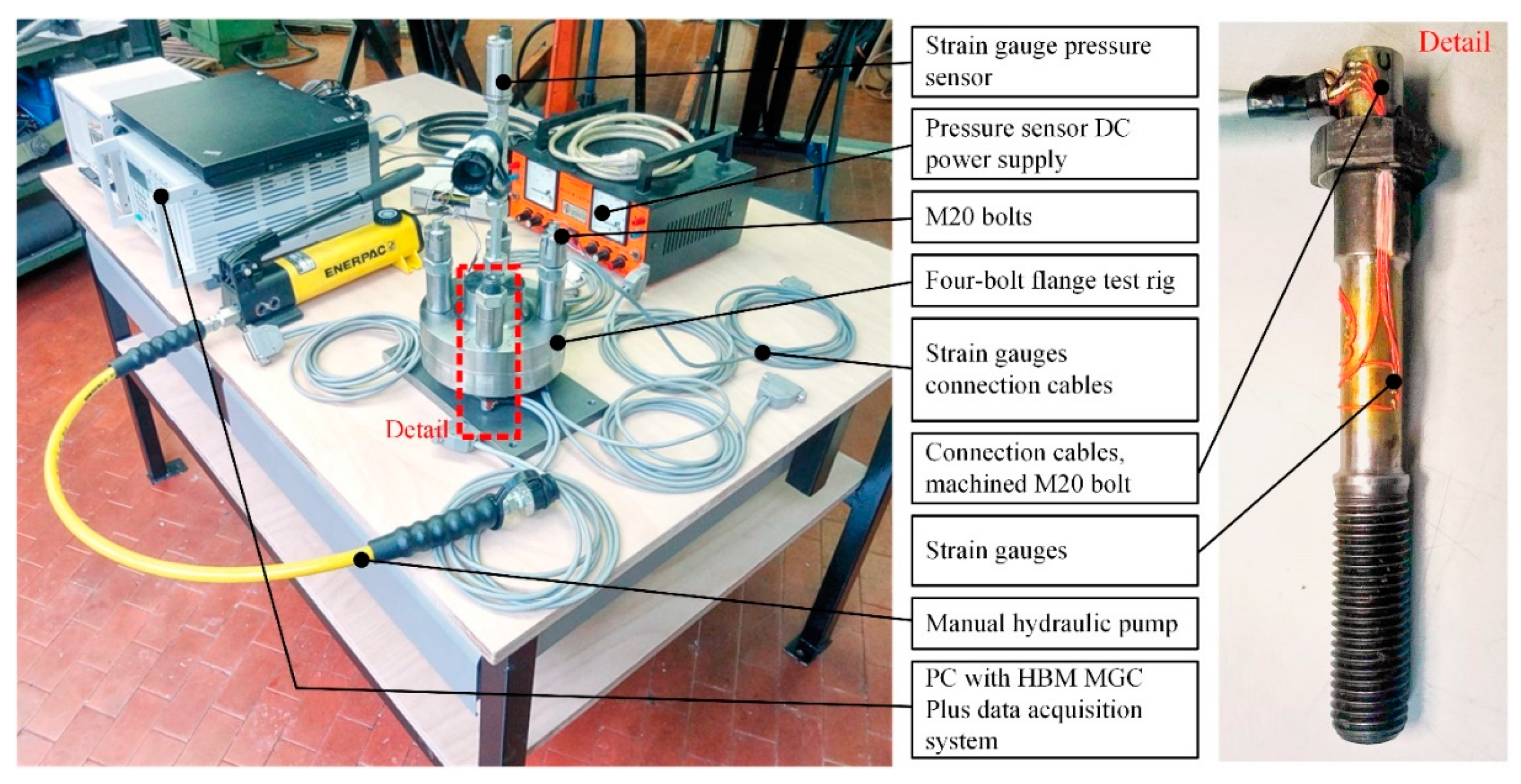
4. Experimental Analysis
Results of the Finite Element Analyses
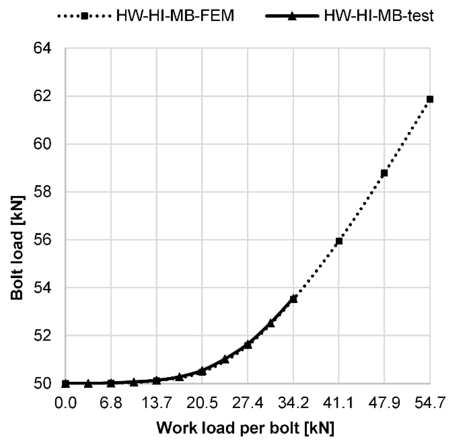
5. Comparison of Analytical and Numerical Results
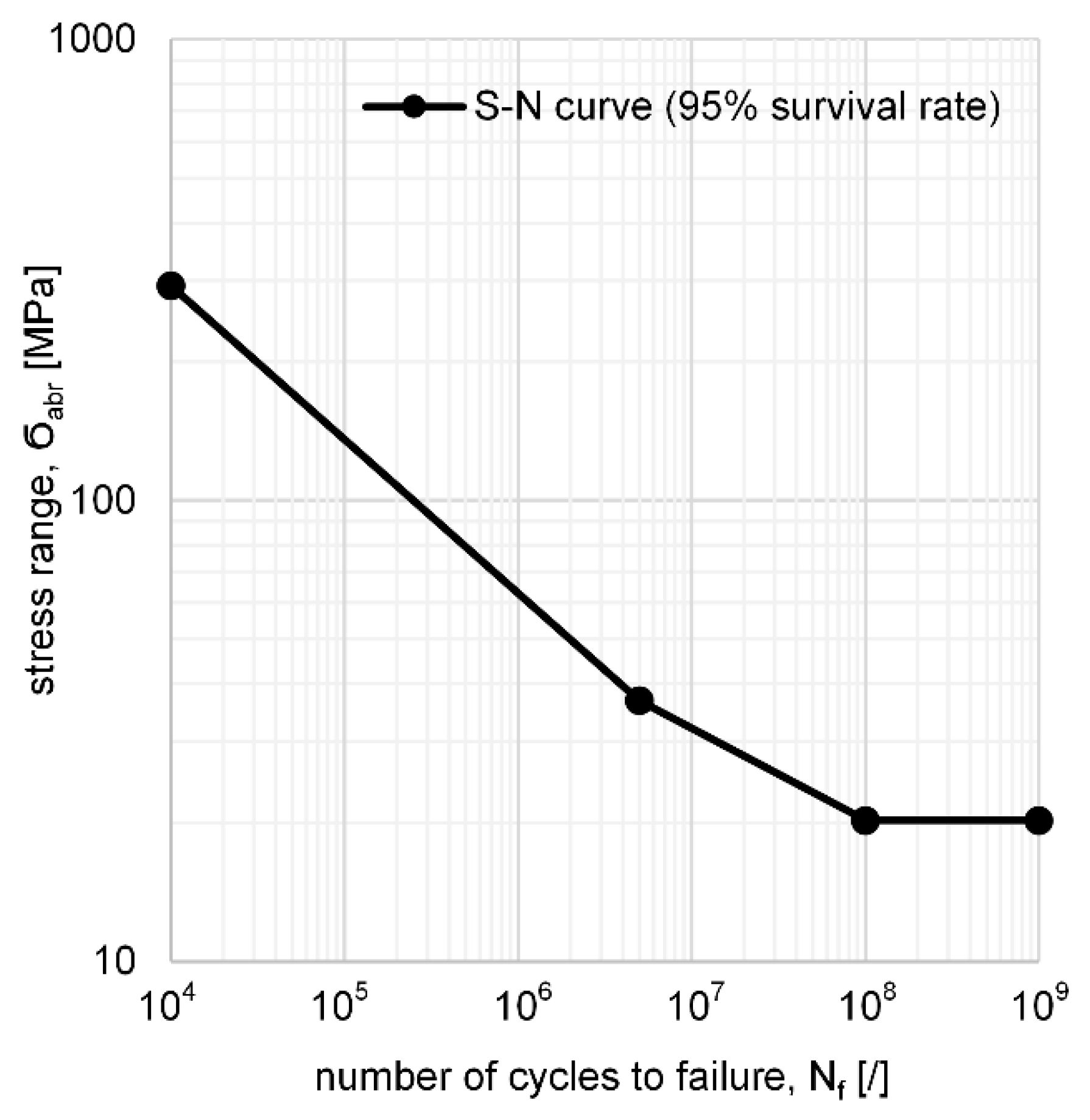
6. Fatigue Life Calculation
7. Conclusions
- The additional bolt load increases linearly as long as compressive stresses are present at the inner edge of the flange. When the joint begins to open, the additional load in the bolt starts to increase progressively. Because of this fact, analytical methods are normally valid only to the point when the spreading of the flanges starts to occur.
- The experimental verification confirmed that the FEM analysis can be considered as a reference method, as the FEM analysis results proved to be accurate even in the absolute terms.
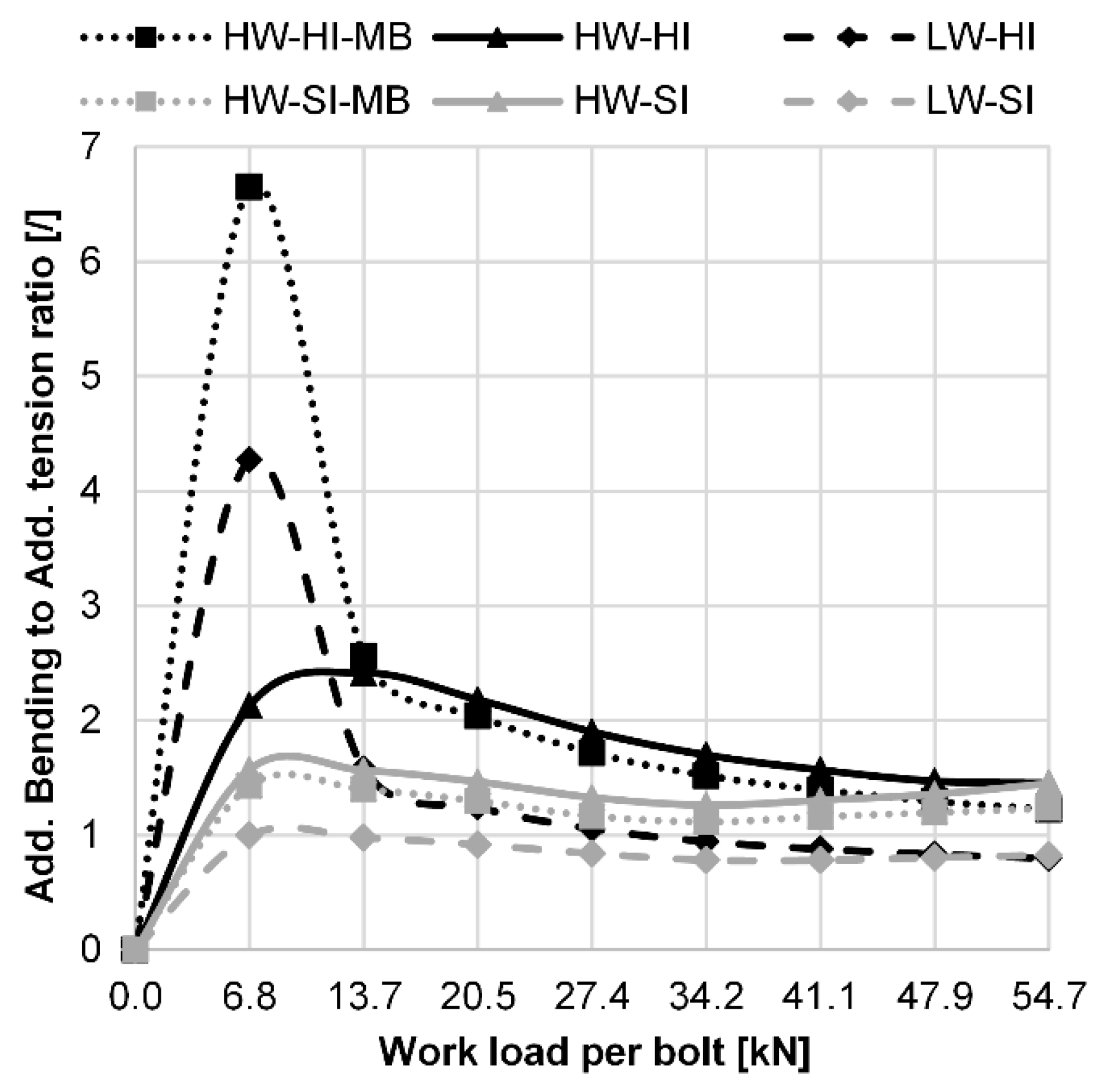
- Due to the eccentricity of the working load, bending stresses occur in the bolt and account for a large proportion of the total stress range in the bolt. The additional bending-to-tensile stress ratio can be as high as 6 for lower working loads and about 1 for very high working loads.
- By using a high washer under the nut, the stress range and the risk of fatigue damage to the bolt are significantly reduced. In our case, the increase in fatigue life of the bolt is about 300%–500% (depending on the geometry and working load). There are two reasons for the lower amplitude (i.e., lower stress range) when a long washer is used: the first reason is the reduced additional load in the bolt, and the second reason is the reduced additional bending stress in the bolt, which is almost completely eliminated from the bolt threaded region due to the long washer.
- By using a high washer, the critical point of the bolt is shifted from the first contact of the bolt thread with the nut thread to the transition of the shank to the bolt head. The reduced notch effect and larger cross-section at this point greatly increases the fatigue life of the bolt.
- The application of the used analytical method is very challenging when considering the bending stress component in the bolt, as it requires the evaluation of many factors whose values are difficult to determine accurately. This can lead to large deviations from the results obtained by the FEM analysis or experimentaly. For this reason, the analytical results in our research deviate significantly from the experimental or FEM analysis results.
- Note that the mesh size and the type of elements used are known to affect the results of the FEM analyses. For our example, the size of the model is still acceptable, which contains at least three elements in thickness, i.e., about 30,000 elements.
Supplementary Materials
Author Contributions
Funding
Data Availability Statement
Conflicts of Interest
References
- Budynas, R.G.; Nisbett, J.K. Shigley’s Mechanical Engineering Design; McGrawHill: New York, NY, USA, 2011. [Google Scholar]
- Niemann, G.; Winter, H.; Höhn, B.R.; Stahl, K. Maschinenelemente 1—Konstruktion und Berechnung von Verbindungen, Lagern, Wellen; Springer: Berlin/Heidelberg, Germany, 2019. [Google Scholar]
- Schmid, S.R.; Hamrock, B.J.; Jacobson, B.O. Fundamentals of Machine Elements; CRC Press: Boca Raton, FL, USA, 2014. [Google Scholar]
- Oman, S.; Nagode, M. Bolted Connection of an End-Plate Cantilever Beam: The Distribution of Operating Force. Stroj. Vestn. J. Mech. Eng. 2017, 63, 617–627. [Google Scholar] [CrossRef] [Green Version]
- Griza, S.; Bertoni, F.; Zanon, G.; Reguly, A.; Strohaecker, T. Fatigue in engine connecting rod bolt due to forming laps. Eng. Fail. Anal. 2009, 16, 1542–1548. [Google Scholar] [CrossRef]
- European Committee for Standardization. EN 1591-1:2014 Flanges and Their Joints—Design Rules for Gasketed Circular Flange Connections—Part 3: Calculation; European Committee for Standardization: Brussels, Belgium, 2014. [Google Scholar]
- Jaszak, P. The elastic serrated gasket of the flange bolted joints. Int. J. Press. Vessel. Pip. 2019, 176, 103954. [Google Scholar] [CrossRef]
- Abid, M.; Nash, D.H.; Javed, S.; Wajid, H.A. Performance of a gasket joint ander bolt up and combined pressure, axial and thermal loading—FEA study. Int. J. Press. Vessel. Pip. 2018, 168, 166–173. [Google Scholar] [CrossRef] [Green Version]
- Jaszak, P.; Adamek, K. Design and analysis of the flange-bolted joint with respect to required tightness and strength. Open Eng. 2019, 9, 338–349. [Google Scholar] [CrossRef]
- Cao, J.; Zhang, Z. Finite element analysis and mathematical characterization of contact pressure distribution in bolted joints. J. Mech. Sci. Technol. 2019, 33, 4715–4725. [Google Scholar] [CrossRef]
- Van-Long, H.; Jean-Pierre, J.; Jean-François, D. Behaviour of bolted flange joints in tubular structures under monotonic, repeated and fatigue loadings I: Experimental tests. J. Constr. Steel Res. 2013, 85, 1–11. [Google Scholar] [CrossRef]
- Shirani, M.; Härkegård, G. Fatigue life distribution and size effect in ductile cast iron for wind turbine components. Eng. Fail. Anal. 2011, 18, 12–24. [Google Scholar] [CrossRef]
- Pavlović, M.; Heistermann, C.; Veljković, M.; Pak, D.; Feldmann, M.; Rebelo, C.; da Silva, L.S. Connections in towers for wind converters, part I: Evaluation of down scaled experiments. J. Constr. Steel Res. 2015, 115, 445–457. [Google Scholar] [CrossRef]
- Ajaei, B.B.; Soyoz, S. Effects of preload deficiency on fatigue demands of wind turbine tower bolts. J. Constr. Steel Res. 2020, 166, 105933. [Google Scholar] [CrossRef]
- Cornwell, R.E. Computation of load factors in bolted connections. Proc. Inst. Mech. Eng. Part C J. Mech. Eng. Sci. 2008, 223, 795–808. [Google Scholar] [CrossRef]
- Cardoso, R.C.; Nascimento, B.L.; Thompson, F.D.F.; Griza, S. Study of bolted joint axial stiffness using finite element analyses, experimental tests, and analytical calculations. Proc. Inst. Mech. Eng. Part C J. Mech. Eng. Sci. 2020, 234, 4671–4681. [Google Scholar] [CrossRef]
- VDI. VDI 2230-1: 2015 Systematic Calculation of Highly Stressed Bolted Joints—Joints with One Cylindrical Bolt; VDI Verlag: Diseldorf, Germany, 2015. [Google Scholar]
- European Committee for Standardization. EN 1092-1:2018 Flanges and Their Joints—Circular Flanges for Pipes, Valves, Fittings and Accessories, PN Designated—Part 1: Steel Flanges; European Committee for Standardization: Brussels, Belgium, 2018. [Google Scholar]
- Zhu, L.; Bouzid, A.-H.; Hong, J. Analytical evaluation of elastic interaction in bolted flange joints. Int. J. Press. Vessel. Pip. 2018, 165, 176–184. [Google Scholar] [CrossRef]
- Wileman, J.; Choudhury, M.; Green, I. Computation of Member Stiffness in Bolted Connections. J. Mech. Des. 1991, 113, 432–437. [Google Scholar] [CrossRef]
- Lehnhoff, T.F.; Ko, K.I.; McKay, M.L. Member Stiffness and Contact Pressure Distribution of Bolted Joints. J. Mech. Des. 1994, 116, 550–557. [Google Scholar] [CrossRef]
- Lehnhoff, T.F.; Bunyard, B.A. Effects of Bolt Threads on the Stiffness of Bolted Joints. J. Press. Vessel. Technol. 2000, 123, 161–165. [Google Scholar] [CrossRef]
- Musto, J.C.; Konkle, N.R. Computation of Member Stiffness in the Design of Bolted Joints. J. Mech. Des. 2005, 128, 1357–1360. [Google Scholar] [CrossRef]
- Naruse, T.; Shibutani, Y. Equivalent stiffness evaluations of clamped plates in bolted joints under loading. J. Solid Mech. Mater. Eng. 2010, 2, 1791–1805. [Google Scholar] [CrossRef] [Green Version]
- Coria, I.; Martin, I.; Bouzid, A.H.; Heras, I.; Abasolo, M. Efficient assembly of bolted joints under external loads using numerical FAM. Int. J. Mech. Sci. 2018, 142, 575–582. [Google Scholar] [CrossRef]
- Williams, J.G.; Anley, R.E.; Nash, D.H.; Gray, T.G.F. Analysis of externaly loaded bolted joints: Analitical, computational and experimental study. Int. J. Press. Vessel. Pip. 2009, 86, 420–427. [Google Scholar] [CrossRef] [Green Version]
- Shi, G.; Shi, Y.; Wang, Y.; Bradford, M.A. Numerical simulation of steel pretensioned bolted end-plate connections of different types and details. Eng. Struct. 2008, 30, 2677–2686. [Google Scholar] [CrossRef]
- Diaz, C.; Victoria, M.; Martí, P.; Querin, O.M.; Martí-Montrull, P. FE model of beam-to-column extended end-plate joints. J. Constr. Steel Res. 2011, 67, 1578–1590. [Google Scholar] [CrossRef]
- Drosopoulos, G.; Stavroulakis, G.; Abdalla, K. 3D Finite element analysis of end—Plate steel joints. Steel Compos. Struct. 2012, 12, 93–115. [Google Scholar] [CrossRef]
- Wang, M.; Shi, Y.; Wang, Y.; Shi, G. Numerical study on seismic behaviours of steel frame end-plate connections. J. Constr. Steel Res. 2013, 90, 140–152. [Google Scholar] [CrossRef]
- Saberi, V.; Gerami, M.; Kheyroddin, A. Comparison of bolted end plate and T-stub connection sensitivity to component thickness. J. Constr. Steel Res. 2014, 98, 134–145. [Google Scholar] [CrossRef]
- El-Khoriby, S.; Sakr, M.A.; Khalifa, T.M.; Eladly, M.M. Modelling and behaviour of beam-to-column connections under axial force and cyclic bending. J. Constr. Steel Res. 2017, 129, 171–184. [Google Scholar] [CrossRef]
- Griza, S.; da Silva, M.E.G.; dos Santos, S.V. The effect of bolt length in the fatigue strength of M24x3 bolt studs. Eng. Fail. Anal. 2013, 34, 397–406. [Google Scholar] [CrossRef]
- Griza, S.; da Silva, M.E.G.; dos Santos, S.V.; Strohaecker, T.R. Experimental evaluation of cyclic stresses on axially loaded bolted joints. Proc. Inst. Mech. Eng. Part C. J. Mech. Eng. Sci. 2016, 230, 2611–2622. [Google Scholar] [CrossRef]
- ECCS. European Recommendations for Bolted Connections in Structural Steelwork; ECCS: Brussels, Belgium, 1985; Volume 38. [Google Scholar]
- Gurney, T.R. Fatigue of Welded Structures; Cambridge University Press: Cambridge, UK, 1968. [Google Scholar]
- European Committee for Standardization. EN 1993-1-9, Eurocode 3: Design of Steel Structures—Part 1–9: Fatigue; European Committee for Standardization (CEN): Brussels, Belgium, 2005. [Google Scholar]


| Geometry | δS [mm/N] | δP [mm/N] | δP* [mm/N] | δP** [mm/N] | n | φen* [−] | FA [kN] | FSA [kN] | σSAt [MPa] | σSAb* [MPa] | σabr [MPa] |
|---|---|---|---|---|---|---|---|---|---|---|---|
| HW-HI-MB | 3.06 × 10⁻⁶ | 1.07 × 10⁻⁶ | 1.07 × 10⁻⁶ | 1.07 × 10⁻⁶ | 0.1 | 0.026 | 13.6 | 0.36 | 1.45 | 9.44 | 10.89 |
| HW-SI-MB | 3.06 × 10⁻⁶ | 2.04 × 10⁻⁶ | 2.04 × 10⁻⁶ | 2.04 × 10⁻⁶ | 0.1 | 0.040 | 13.6 | 0.55 | 2.23 | 25.15 | 27.38 |
| LW-HI | 1.53 × 10⁻⁶ | 3.19 × 10⁻⁷ | 1.29 × 10⁻⁷ | 1.31 × 10⁻⁷ | 0.3 | 0.021 | 13.6 | 0.29 | 1.15 | 20.86 | 22.01 |
| LW-SI | 1.53 × 10⁻⁶ | 1.28 × 10⁻⁶ | 1.34 × 10⁻⁶ | 7.57 × 10⁻⁷ | 0.3 | 0.079 | 13.6 | 1.08 | 4.41 | 52.32 | 56.73 |
| HW-HI-MB, n = 1 | 3.06 × 10⁻⁶ | 1.07 ×1 0−6 | 1.07 × 10⁻⁶ | 1.07 × 10⁻⁶ | 1.0 | 0.260 | 13.6 | 3.56 | 14.51 | 0.00 | 14.51 |
| HW-SI-MB, n = 1 | 3.06 × 10⁻⁶ | 2.04 ×1 0−6 | 2.04 × 10⁻⁶ | 2.04 × 10⁻⁶ | 1.0 | 0.400 | 13.6 | 5.47 | 22.31 | 0.00 | 22.31 |
| LW-HI, n = 1 | 1.53 × 10⁻⁶ | 3.62 × 10⁻⁷ | 3.62 × 10⁻⁷ | 3.62 × 10⁻⁷ | 1.0 | 0.171 | 13.6 | 2.33 | 9.52 | 0.00 | 9.52 |
| LW-SI, n = 1 | 1.53 × 10⁻⁶ | 1.32 × 10⁻⁶ | 1.32 × 10⁻⁶ | 1.32 × 10⁻⁶ | 1.0 | 0.446 | 13.6 | 6.10 | 24.92 | 0.00 | 24.92 |
| Mesh Size Description | Number of Elements | Number of Nodes | Elements Type | FA [kN] | FSA [kN] | σSAt [MPa] | σSAb* [MPa] |
|---|---|---|---|---|---|---|---|
| 3 or more elements by thickness | 219,398 | 956,641 | Quadratic | 13.6 | 0.141 | 0.448 | 1.266 |
| 3 or more elements by thickness | 219,398 | 245,993 | Linear | 13.6 | 0.139 | 0.442 | 1.275 |
| 3 elements by thickness | 29,774 | 144,073 | Quadratic | 13.6 | 0.128 | 0.406 | 1.108 |
| 3 elements by thickness | 29,774 | 38,232 | Linear | 13.6 | 0.125 | 0.397 | 1.124 |
| 1-2 elements by thickness | 5596 | 29,060 | Quadratic | 13.6 | 0.146 | 0.464 | 1.387 |
| 1-2 elements by thickness | 5596 | 7891 | Linear | 13.6 | 0.101 | 0.321 | 0.918 |
| Quadratic elements: C3D20R | - | - | - | - | - | - | |
| Linear elements: C3D8R | - | - | - | - | - | - | |
| Analysis Type | Geometry | FA [kN] | FSA [kN] | σSAt [MPa] | σSAb* [MPa] | σSAb [MPa] |
|---|---|---|---|---|---|---|
| Analytical | HW-HI-MB | 13.6 | 0.356 | 1.5 | 9.4 | 10.9 |
| HW-SI-MB | 13.6 | 0.547 | 2.2 | 25.2 | 27.4 | |
| LW-HI | 13.6 | 0.281 | 1.1 | 20.8 | 22.0 | |
| LW-SI | 13.6 | 1.080 | 4.4 | 52.3 | 56.7 | |
| Numerical: Thread | HW-HI-MB | 13.6 | 0.112 | 0.5 | 0.2 | 0.6 |
| HW-SI-MB | 13.6 | 1.553 | 6.3 | 1.7 | 8.0 | |
| LW-HI | 13.6 | 0.257 | 1.0 | 1.8 | 2.8 | |
| LW-SI | 13.6 | 3.074 | 12.5 | 11.2 | 23.8 |
| Analysis Type | Geometry | Work Load [kN] | |||||||
|---|---|---|---|---|---|---|---|---|---|
| 6.84 | 13.68 | 20.53 | 27.37 | 34.2 | 41.05 | 47.89 | 54.74 | ||
| Numerical: Head-Shank Transition | HW-HI-MB | 0.39 | 1.91 | 6.05 | 16.78 | 33.21 | 52.42 | 73.44 | 95.35 |
| HW-HI | 0.27 | 1.72 | 6.02 | 17.67 | 35.79 | 56.94 | 79.68 | 98.91 | |
| HW-SI-MB | 6.40 | 13.74 | 23.10 | 33.52 | 45.16 | 59.29 | 76.33 | 94.20 | |
| HW-SI | 7.25 | 15.53 | 26.14 | 37.91 | 50.75 | 65.63 | 83.17 | 97.98 | |
| LW-HI | 0.31 | 2.12 | 7.49 | 21.36 | 42.16 | 66.02 | 91.57 | 118.23 | |
| LW-SI | 9.03 | 19.33 | 32.62 | 47.62 | 64.29 | 81.39 | 100.91 | 122.87 | |
| Numerical: Thread | HW-HI-MB | 0.05 | 0.61 | 2.49 | 8.29 | 18.26 | 30.78 | 45.36 | 61.47 |
| HW-HI | 0.02 | 0.52 | 2.24 | 7.54 | 16.70 | 28.23 | 41.74 | 59.87 | |
| HW-SI-MB | 3.69 | 8.02 | 14.10 | 21.70 | 29.90 | 38.54 | 49.10 | 60.20 | |
| HW-SI | 3.42 | 7.43 | 13.14 | 20.37 | 28.23 | 36.00 | 45.85 | 59.40 | |
| LW-HI | 0.48 | 2.84 | 9.58 | 26.65 | 52.20 | 81.51 | 112.96 | 145.82 | |
| LW-SI | 11.10 | 23.77 | 40.16 | 58.75 | 79.48 | 100.67 | 124.67 | 151.56 | |
| Analytical | HW-HI-MB | 5.44 | 10.89 | 16.33 | 21.77 | 27.22 | 32.66 | 38.10 | 43.55 |
| HW-SI-MB | 13.69 | 27.38 | 41.07 | 54.77 | 68.46 | 82.15 | 95.84 | 109.53 | |
| LW-HI | 11.00 | 21.99 | 32.99 | 43.98 | 54.98 | 65.97 | 76.97 | 87.96 | |
| LW-SI | 28.35 | 56.71 | 85.06 | 113.41 | 141.77 | 170.12 | 198.47 | 226.82 | |
| Analysis Type | Geometry | Work Load [kN] | |||||||
|---|---|---|---|---|---|---|---|---|---|
| 6.84 | 13.68 | 20.53 | 27.37 | 34.2 | 41.05 | 47.89 | 54.74 | ||
| Numerical: Head-Shank Transition | HW-HI-MB | INF | INF | INF | INF | 8.40 × 10⁶ | 1.74 × 10⁶ | 6.31 × 10⁵ | 2.88 × 10⁵ |
| HW-HI | INF | INF | INF | INF | 5.78 × 10⁶ | 1.35 × 10⁶ | 4.94 × 10⁵ | 2.58 × 10⁵ | |
| HW-SI-MB | INF | INF | 5.16 × 10⁷ | 8.02 × 10⁶ | 2.71 × 10⁶ | 1.20 × 10⁶ | 5.62 × 10⁵ | 2.99 × 10⁵ | |
| HW-SI | INF | INF | 2.78 × 10⁷ | 4.59 × 10⁶ | 1.91 × 10⁶ | 8.84 × 10⁵ | 4.35 × 10⁵ | 2.66 × 10⁵ | |
| LW-HI | INF | INF | INF | 7.64 × 10⁷ | 3.34 × 10⁶ | 8.69 × 10⁵ | 3.26 × 10⁵ | 1.51 × 10⁵ | |
| LW-SI | INF | INF | 9.18 × 10⁶ | 2.31 × 10⁶ | 9.41 × 10⁵ | 4.64 × 10⁵ | 2.43 × 10⁵ | 1.35 × 10⁵ | |
| Numerical: Thread | HW-HI-MB | INF | INF | INF | INF | INF | 1.23 × 10⁷ | 2.68 × 10⁶ | 1.08 × 10⁶ |
| HW-HI | INF | INF | INF | INF | INF | 1.89 × 10⁷ | 3.44 × 10⁶ | 1.16 × 10⁶ | |
| HW-SI-MB | INF | INF | INF | 7.05 × 10⁷ | 1.42 × 10⁷ | 4.37 × 10⁶ | 2.11 × 10⁶ | 1.15 × 10⁶ | |
| HW-SI | INF | INF | INF | 9.68 × 10⁷ | 1.89 × 10⁷ | 5.61 × 10⁶ | 2.59 × 10⁶ | 1.19 × 10⁶ | |
| LW-HI | INF | INF | INF | 2.52 × 10⁷ | 1.76 × 10⁶ | 4.62 × 10⁵ | 1.73 × 10⁵ | 8.06 × 10⁴ | |
| LW-SI | INF | 4.47 × 10⁷ | 3.86 × 10⁶ | 1.23 × 10⁵ | 4.98 × 10⁵ | 2.45 × 10⁵ | 1.29 × 10⁵ | 7.1 × 10⁴ | |
| Analytical | HW-HI-MB | INF | INF | INF | 6.93 × 10⁷ | 2.27 × 10⁷ | 9.13 × 10⁶ | 4.52 × 10⁶ | 3.03 × 10⁶ |
| HW-SI-MB | INF | 2.20 × 10⁷ | 3.61 × 10⁶ | 1.52 × 10⁶ | 7.79 × 10⁵ | 4.51 × 10⁵ | 2.84 × 10⁵ | 1.90 × 10⁵ | |
| LW-HI | INF | 6.60 × 10⁷ | 8.69 × 10⁶ | 2.94 × 10⁶ | 1.50 × 10⁶ | 8.71 × 10⁵ | 5.48 × 10⁵ | 3.67 × 10⁵ | |
| LW-SI | 1.85 × 10⁷ | 1.37 × 10⁶ | 4.06 × 10⁵ | 1.71 × 10⁵ | 8.77 × 10⁴ | 5.08 × 10⁴ | 3.20 × 10⁴ | 2.14 × 10⁴ | |
Publisher’s Note: MDPI stays neutral with regard to jurisdictional claims in published maps and institutional affiliations. |
© 2021 by the authors. Licensee MDPI, Basel, Switzerland. This article is an open access article distributed under the terms and conditions of the Creative Commons Attribution (CC BY) license (http://creativecommons.org/licenses/by/4.0/).
Share and Cite
Okorn, I.; Nagode, M.; Klemenc, J.; Oman, S. Analysis of Additional Load and Fatigue Life of Preloaded Bolts in a Flange Joint Considering a Bolt Bending Load. Metals 2021, 11, 449. https://doi.org/10.3390/met11030449
Okorn I, Nagode M, Klemenc J, Oman S. Analysis of Additional Load and Fatigue Life of Preloaded Bolts in a Flange Joint Considering a Bolt Bending Load. Metals. 2021; 11(3):449. https://doi.org/10.3390/met11030449
Chicago/Turabian StyleOkorn, Ivan, Marko Nagode, Jernej Klemenc, and Simon Oman. 2021. "Analysis of Additional Load and Fatigue Life of Preloaded Bolts in a Flange Joint Considering a Bolt Bending Load" Metals 11, no. 3: 449. https://doi.org/10.3390/met11030449
APA StyleOkorn, I., Nagode, M., Klemenc, J., & Oman, S. (2021). Analysis of Additional Load and Fatigue Life of Preloaded Bolts in a Flange Joint Considering a Bolt Bending Load. Metals, 11(3), 449. https://doi.org/10.3390/met11030449