Article

The Effect of Flow Lines on the Mechanical Properties in Hot-Rolled Bearing Steel

1
School of Materials Science and Engineering, Wuhan University of Technology, Wuhan 430070, China
2
Hubei Key Laboratory of Advanced Technology for Automotive Components, Wuhan 430070, China
3
Hubei Engineering Research Center for Green Precision Material Forming, Wuhan 430070, China
*
Author to whom correspondence should be addressed.
Metals 2021, 11(3), 456; https://doi.org/10.3390/met11030456
Submission received: 20 February 2021 / Revised: 6 March 2021 / Accepted: 6 March 2021 / Published: 10 March 2021
(This article belongs to the Special Issue Fatigue Behavior and Crack Mechanism of Metals and Alloys)

Abstract

:
Hot rolling is an essential process for the shape-forming of bearing steel. It plays a significant role in the formation and distribution of flow lines. In this work, the effect of flow lines is investigated by analyzing the microstructure and mechanical anisotropy of hot-rolled bearing steel. It was found that carbides rich with Cr and Mn elements are distributed unevenly along the flow-line direction of the hot-rolled bearing steel. Moreover, the mechanical characterization indicates that ultimate tensile strength and yield strength do not have any significant difference in two directions. Nevertheless, an ultrahigh section shrinkage of 57.51% is obtained in the 0° sample that has parallel flow lines, while 90° sample shows poor section shrinkage. The uneven distributed carbides will affect the direction and speed of crack propagation during tensile deformation. Therefore, the 0° and 90° samples exhibit great difference in plastic property. Meanwhile, after tensile deformation, a delaminated texture is observed in the flow lines, which may be caused by different degrees of deformation of grains due to the uneven distribution of carbides. The results of this work may provide guidance for controlling and optimizing flow lines in the manufacturing of bearing rings.

1. Introduction

The hot rolling process is essential for the shape-forming of bearing steel and it directly influences the formation and distribution of flow lines [1,2,3,4,5]. However, flow lines that are induced by the hot rolling process play a crucial role in determining the final performance of the workpieces. Therefore, it is necessary to conduct research on flow lines in order to control the properties of hot-rolled bearing steel.
Many researches have been conducted to study the formation mechanism of flow lines, in which the widely acknowledged factors were distribution of segregation, inclusions, or carbides along with the flow-line direction. Jiang et al. [6,7] investigated the behavior of the microstructure evolution of the bearing rings during hot rolling and found that the flow lines were consistent with the distribution of carbides. Li et al. [8] reported that the band-shape or chain-shape distribution of inclusions could cause the formation of flow lines during deformation. They also reported that flow lines directly determine the mechanical properties of the workpiece because the distribution of the carbides and inclusions seriously affect cracks initiation and propagation. Chu et al. [9] indicated that cracks were likely to initiate and propagate near the segregation region in high-alloy steels. Tameemi et al. [10] studied the reasons for the initiation of microcracks in a failed planetary bearing. From their study, it was found that inhomogeneous inclusions contributed to microcracks and the length of microcracks was directly proportional to the dimensions of the inclusions. Moreover, the stress concentration that was caused due to the aggregation of carbides leads to the initiation of cracks at the interface of carbide and ferrite, and the abnormal gathering of carbides improves the cracking susceptibility of steels [11,12,13,14]. Therefore, it can be seen that the appearance of defects in steels is probably related to the flow lines according to the internal factors of flow lines formation. Furthermore, flow fines were also considered to influence the anisotropy of mechanical properties in steels. Zhang et al. [15] indicated that the loading direction should be perpendicular to the direction of the flow lines in order to achieve a long service life of the forged workpieces. Jiang et al. [16] investigated the mechanical anisotropy of the forged bearing rings by conducting tensile tests. They revealed that the mechanical properties in the direction parallel to the direction of the flow lines were superior to those in the perpendicular direction. However, the current studies only reveal a phenomenon, and none has explained the correlative mechanism between flow lines and anisotropy.
Recently, the evolution law of flow lines that were formed during the plastic forming of the workpieces was studied and the distribution of flow lines was optimized by optimizing the forming process. Jounet et al. [17] simulated the evolution law of flow lines in multi-pass axisymmetric forging using the finite element method (FEM). They demonstrated that flow lines can be improved using spring-attached dies. Zhang et al. [18] also studied the formation mechanism of flow lines that were formed during the precision forging of a disk workpiece with a complex structure. In their work, the distribution of flow lines was optimized by adjusting the deformation degree, radial resistance, and forging size. Jiang et al. [16] analyzed the evolution law of flow lines that were formed during the hot forging processes using FEM and the results were compared with the experimental results. The results indicated that the applied V-shaped punching pin and punching recess could resolve disordered flow lines. It can be seen that most of the researches on flow lines still exist at the macro level, and there is a lack of research from the micro perspective.
Therefore, this work is focused on investigating flow lines systematically in hot-rolled bearing steel. Further, the influence of flow lines on mechanical anisotropy is studied and the final structure-property relationship is further discussed.

2. Materials and Methods

2.1. Experimental Material
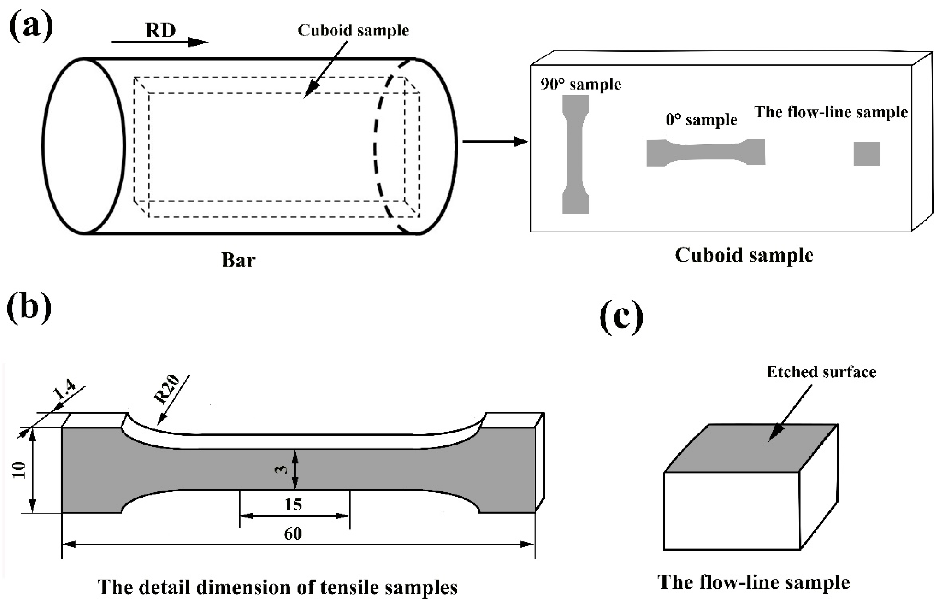
The chemical composition of AISI 52,100 bearing steel used in this work is presented in Table 1. The hot rolling process and sampling method are as follows:
The blank with 240 × 240 mm was casted after being melted in a vacuum induction melting at 1550 °C for 1 h. The casting blank was subjected to eight passes rough rolling, three passes medium rolling, and one pass sizing rolling into a bar with a diameter of ϕ 80 above 900 °C, and then flow lines were formed after rolling. Subsequently, the hot-rolled bar was subjected to the traditional spheroidizing annealing process to obtain a spheroidal pearlite. Finally, a cuboid sample was cut from the bar along the axial direction with dimension of 220 × 70 × 10 mm (Figure 1a).

2.2. Tensile Tests

The samples for tensile testing were cut along two different directions at 0° and 90° to the direction of the flow lines (Figure 1a). Though the particular geometry of tensile sample is different from the geometry prescribed by international standards (ISO), the anisotropy of tensile properties can be also reflected to a certain extent due to the identical sample size and same test conditions. The details of the dimensions of the samples are shown in Figure 1b. Further, the tensile tests were conducted at room temperature using an AG-IC universal material testing machine (Shimadzu Systems, China) at a strain rate of 10−3 m/min in order to obtain the mechanical properties of the tensile samples in the two directions, in terms of ultimate tensile strength, yield strength, elongation, and section shrinkage. The values of all the mechanical properties were calculated as the average value of three samples, and deviations were also calculated for elongation.

2.3. Microstructure Observation

The flow-line sample with size of 5 × 5 × 10 mm was cut from the cuboid sample (Figure 1c). Further, they were mechanically polished and then etched in a water solution containing saturated picric acid (volume fraction) for 3 min at 60~70 °C. Thereafter, the flow lines of the sample were investigated using an optical microscope (OM), electron probe microanalysis (EPMA), and the microstructure was investigated using a field emission scanning electron microscope (SEM, FEI Quanta 450). Furthermore, the distribution of chemical elements was also examined using an electron probe microanalysis (EPMA, JXA-8230/INCAX-ACT, Japan). Besides, the texture distribution of the flow lines was examined using the Electron Back Scattered Diffraction (EBSD). Before the examination, the samples used for EBSD analysis were first mechanically polished, followed by ultrasonic cleaned with acetone, and finally polished with reactive oxide polishing suspension (OPS) in the polishing disc. The fractures of the tensile samples were also characterized using OM, EPMA, and SEM. The microstructure perpendicular to the plane of fracture was examined using EBSD.

3. Results

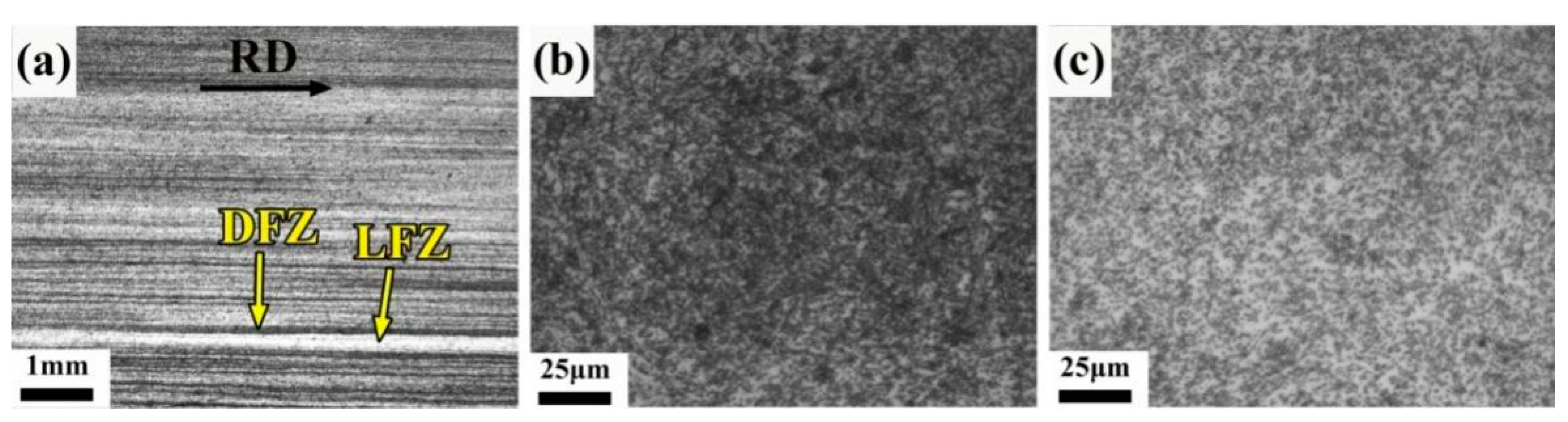
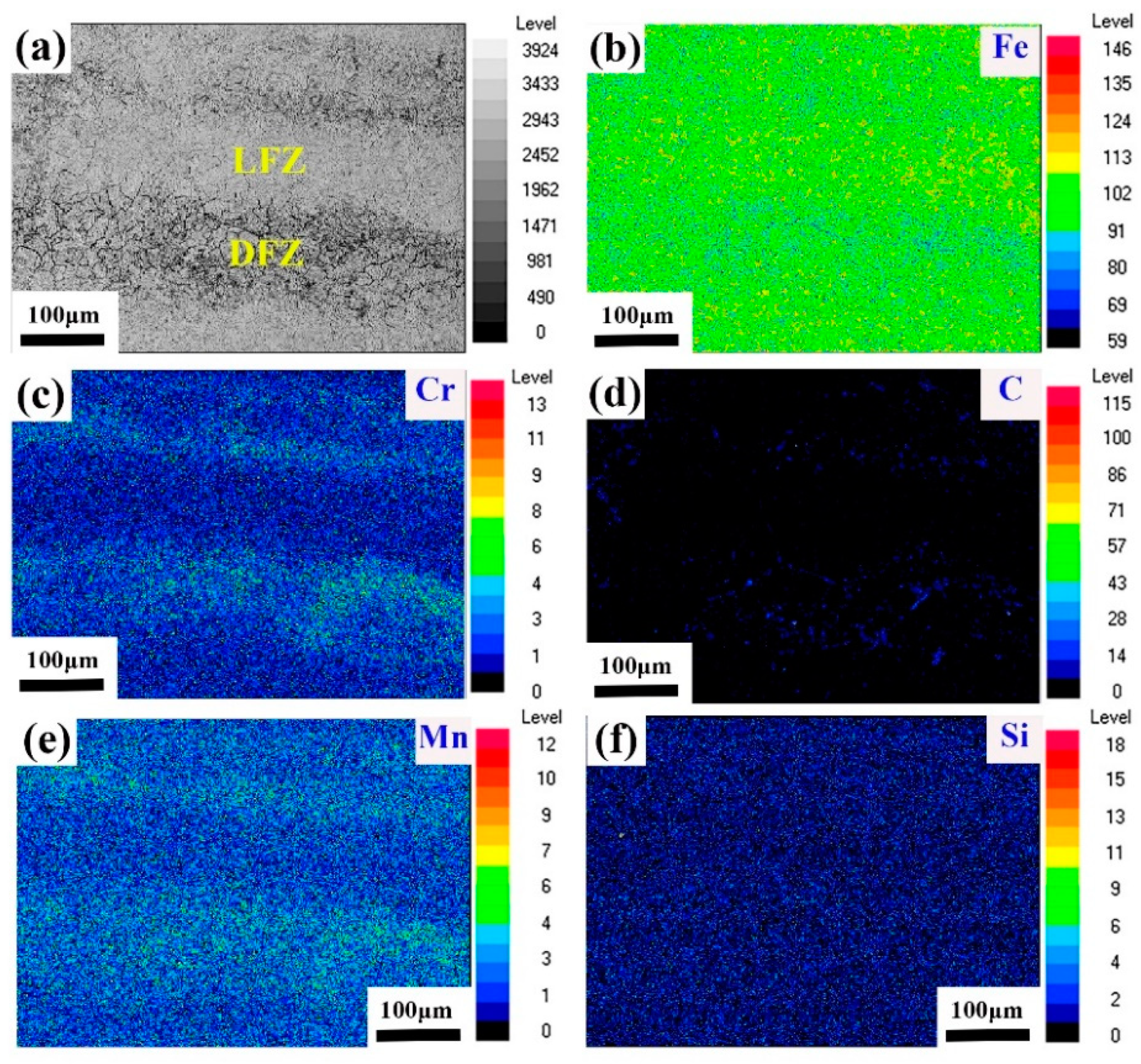
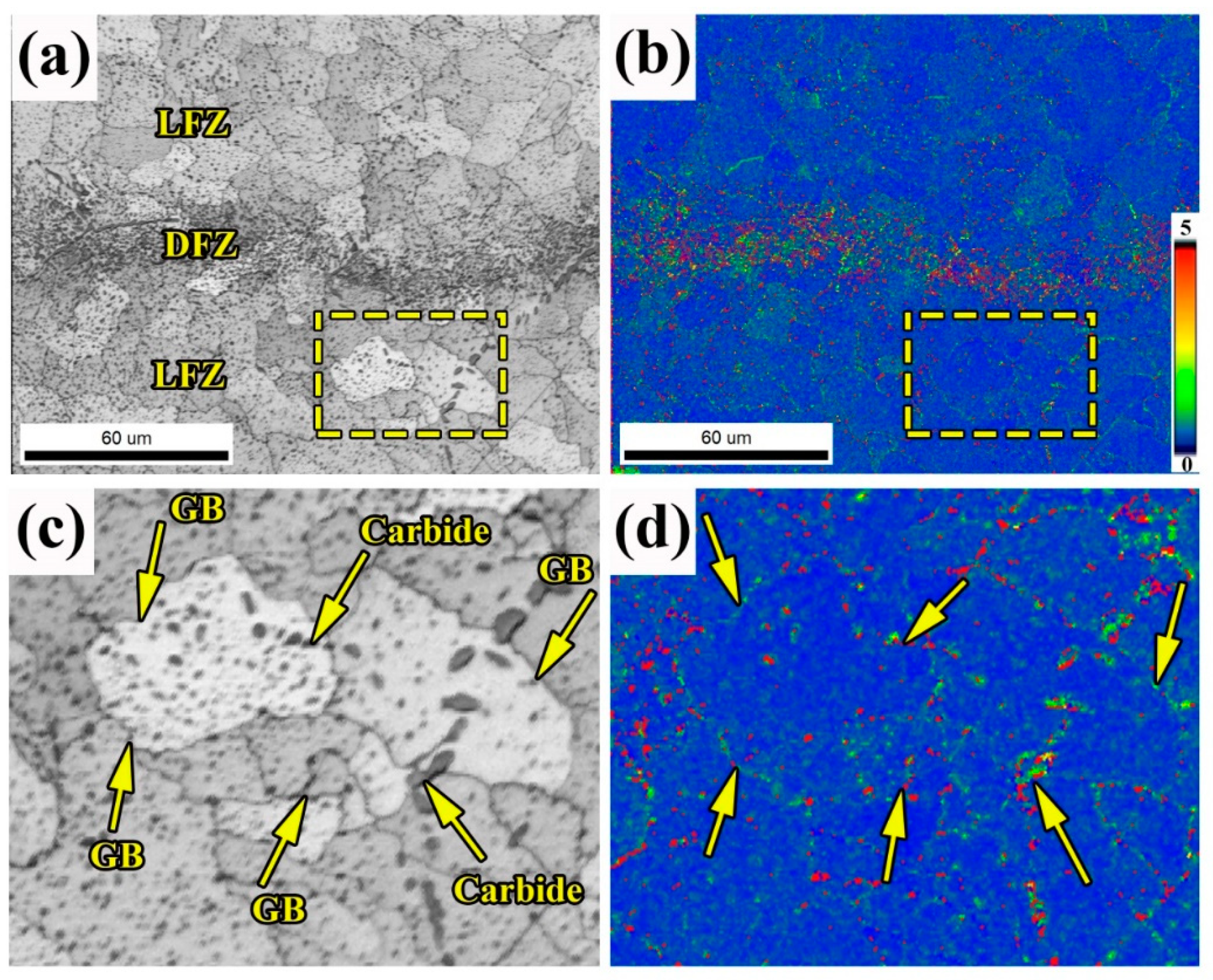
3.1. Microstructure Investigations

The flow lines of the sample consisted of a dark zone and the light zone, parallel to the rolling direction (RD) (Figure 2a). For the sake of statement, the dark zone is called the dark flow-line zone (DFZ) and the light zone is called the light flow-line zone (LFZ). The magnified images of the DFZ and the LFZ are shown in Figure 2b,c, respectively. From the figures, it is found that a large number of carbides are dispersed on the ferrite matrix in the DFZ, while the amount of carbides is relatively lower in the LFZ.
The results of the EPMA mapping of flow lines in hot-rolled bearing steel are shown in Figure 3. The secondary electron image of the flow lines is shown in Figure 3a, in which the DFZ and LFZ are clearly distinguished. Further, Figure 3b–f show the distribution of main elements such as Fe, Cr, C, Mn, and Si in the secondary electron image. From the figures, it is found that more C, Cr, and Mn elements are concentrated in the DFZ. Thus, it is inferred that the flow lines correspond to the concentrated distribution of C, Cr, and Mn elements along the RD in the hot-rolled bearing steel.
The SEM images of the DFZ and LFZ that were etched for 3 min are shown in Figure 4. It is observed that the spherical carbides are densely distributed on the ferrite matrix. Moreover, the aggregation of carbides at grain boundaries (GBs) and some coarse carbides are also observed. Further, it is observed that there are fewer carbides and aggregation in the LFZ (Figure 4b).
Furthermore, the etched time was prolonged to 6 min in order to observe the difference between the DFZ and LFZ (Figure 4c,d). By comparing Figure 4 and Figure 4a, it was observed that deeper corrosion traces are found in Figure 4c than Figure 4a. Moreover, the GBs are clearly observed due to the deeply etched pits at the GBs. However, in the LFZ, the ferrite matrix almost remains unchanged, except for the clear GBs (Figure 4d). This indicates that the LFZ has a better corrosion resistance than the DFZ in the flow lines.
The diameters of the carbides in the DFZ and LFZ were measured, as shown in Figure 5. From Figure 5, it is observed that the diameters of the carbides in the DFZ and LFZ range from 0 µm to 1.25 μm. However, the proportion of carbides with the diameters larger than 0.75 μm in the DFZ (30.6%) is significantly higher than that of the LFZ (12.3%). Moreover, the carbides with the diameter larger than 1.25 μm almost are found in the DFZ. This proves that the formation of the DFZ and LFZ in the flow lines is related to the uneven distribution of carbides.
To provide a better description of such heterogeneous microstructure, the flow lines were further characterized in detail by EBSD, as presented in Figure 6 and Figure 7. Figure 6a shows the ferrite grains and non-uniformly distributed carbides. The KAM image reflects the relative micro-strain intensity of the matrix [19,20]. The same result was found—the carbides were densely distributed in the DFZ—which result in strong stress concentration (Figure 6b). As shown in Figure 6c,d, stress concentration occurs at GBs and the coarse carbide position. This indicates that carbide is an important cause of stress concentration.
Figure 7 shows the texture of the flow lines. From Figure 7a, the grain size is not uniform, and the grains is small visibly in the DFZ (Figure 7b,c). It can be also seen from the inverse pole figure (IPF) that no obvious difference of the texture is found in the DFZ and LFZ. This indicates that the uneven distribution of carbide does not significantly affect the texture difference. The texture analysis in the flow lines shows three major components of texture—S{123}<634>, Brass{011}<211>, and Brass R{111}<112>—from the pole figure.

3.2. Mechanical Properties

The engineering stress-strain curves of the samples in two directions were measured and plotted in order to investigate the anisotropy of mechanical properties in hot-rolled bearing steel (Figure 8a). From Figure 8a, it is observed that the difference in the ultimate tensile strength for two directions is less than 20 MPa and the difference in the yield strength is lower than 28 MPa, whereas the engineering strain between 0° and 90° samples is significantly different. As shown in Figure 8b, the average elongation and section shrinkage of the 0° sample are 30.62% and 57.51%, while that of the 90° sample are 22.72% and 30.36%. It can be seen that the elongation and section shrinkage of 0° sample is much higher than that of the 90° sample. Since the higher section shrinkage means the higher ability of plastic deformation during the tensile process, the significant difference in the section shrinkage between the 0° sample and 90° sample indicates the obvious anisotropy of plastic property in hot-rolled bearing steel. As mentioned above, the carbides are distributed inhomogeneously along the flow lines, which could induce stress concentration and influence the plastic deformation of the matrix during the tensile process. Therefore, it is inferred that the flow lines may cause plastic anisotropy.
The fracture surfaces of the samples in two directions were also examined in order to understand the anisotropy mechanism in hot-rolled bearing steel (Figure 9a,b). It can be seen that the 0° sample has significant deformation and obvious shear lips in the cross-section. However, the fracture of the 90° sample is relatively flat, which indicates the rapid fracture occur in the sample (Figure 9b). The magnified microscopic fracture of 0° and 90° samples are exhibited in Figure 9c,d. From the figures, it is found that 0° sample shows only the dimple morphology, while 90° sample shows the cleavage pattern.

3.3. Crack Propagation

The fractured samples in two directions are examined using OM and the results are shown in Figure 10. From Figure 10a, it is observed that the cracks in the 0° sample is tooth-like and the points of inflection occur in the DFZ or at the junction between the DFZ and LFZ. However, the crack in the 90° sample is relatively smooth and the crack propagates along the DFZ (Figure 10b). Moreover, it is found that the crack propagation direction remains unchanged, which indicates that the crack grows rapidly in the 90° sample during the tensile tests.
It can be inferred from the above results that the crack propagation path can be influenced by the distribution of the DFZ and LFZ. Moreover, detailed microscopic analysis was applied for the 0° sample in order to further understand the mechanism behind the process. The OM and EBSD results of the selected region A (Figure 10a) are shown in Figure 11. In Figure 11a, the zone with more carbides refers to the DFZ while the zone with fewer carbides represents the LFZ. Further, it is found that the carbides aggregate at the points of inflection, which indicates that the DFZ plays an important role in the crack propagation behaviors.
In order to study the difference between the microstructures of the DFZ and LFZ, the regions B and C are selected from Figure 11a for further analysis, as shown in Figure 11c–f. It is found that the DFZ and LFZ exhibit different textures after tensile deformation as shown in Figure 11b. From the IPF image in Figure 11c,e, it is observed that the DFZ has a strong gauss {011}<100>and {111}<100> texture, whereas the cube {001}<100> texture is dominated in the LFZ. Furthermore, Figure 11d–f shows the KAM images of the DFZ and LFZ, respectively. Since the KAM value can reflect the micro-strain of the matrix to a certain extent, the micro-strain in the DFZ is larger than that in the LFZ. This indicates a higher stress concentration in the DFZ. The distribution of angle in regions B and C are illustrated in Figure 11g,h. From the figures, it is found that the DFZ has a higher proportion of low angle grain boundaries ranging from 2° to 15° than the LFZ.
The typical tensile crack in the 0° sample is shown in Figure 12a, in which it is observed that many coarse carbides and microvoids are distributed on the ferrite matrix. Moreover, secondary cracks are also found in the zone marked by the yellow box. The regions of I, II, III, and IV are selected for the analysis of the secondary crack propagation. Further, in order to characterize and analyze the secondary crack, the region by yellow box was examined by EBSD. The IPF and KAM images of the secondary crack marked by the yellow box in Figure 12a are shown in Figure 12b,c, respectively. From Figure 12, it is found that the secondary crack initiation first occurs in region I. Due to the dense distribution of some coarse carbides in the region I (Figure 12a), it is assumed that the crack initiation may be closely related to the coarse carbides. Then, the cracks continue to expand towards the inner side and stop at region II, and a new crack is found in region III. This may also be associated with the coarse carbides that appeared in region III. In Figure 12c, higher misorientation is observed around the carbides, denoted using the red dots in regions I and III. This shows that a higher stress concentration is caused due to the presence of coarse carbides.

4. Discussion

4.1. Microstructure Observation

Figure 3 and Figure 4 show that the carbides enriched with Cr and Mn elements are distributed unevenly along the flow-line direction for hot-rolled bearing steel. The uneven distribution of carbide did not affect the texture (Figure 6 and Figure 7). However, during tensile deformation, the carbides affect the grain deformation, as shown in Figure 11g. This will be responsible for the formation of the delamination of texture (Figure 11b). In the DFZ, a strong gauss {011}<100>and {111}<100> texture is observed, whereas in the LFZ, the cube {001}<100> texture is dominated. As shown in Figure 11f,g, a higher proportion of low angle grain boundaries indicates higher deformation degree in the DFZ, which should be attributed to the aggregation of carbides. The densely distributed carbide reduces the continuity of ferrite matrix. Under the same strain, the ferrite grain in the DFZ needs to undergo higher deformation compared with that of the LFZ. In addition, the higher phase boundaries could also be responsible for the higher stress concentration in the DFZ.
It is well-known that a higher Cr element in the matrix improves corrosion resistance. In this work, the corrosion resistance of the DFZ is worse than that of the LFZ (Figure 4), even though the Cr element in the DFZ is obviously higher than that of the LFZ, as shown in Figure 3. Fu et al. [21] indicated that the Cr element has a strong tendency to combine with the C element to form carbides. Therefore, it is inferred that more Cr elements in the DFZ formed carbides than those remaining in the ferrite matrix, thereby resulting in poor corrosion resistance in the DFZ.

4.2. Mechanical Behaviors

4.2.1. Crack Propagation

Figure 10 shows that the DFZ can influence crack propagation direction, and the crack tends to expand along the DFZ. At the same time, it can be found that many microvoids exist around the coarse carbides, and coarse carbides also frequently appear at the initiation and propagation paths of the secondary cracks, as shown in Figure 12a. It can be concluded that the aggregation of carbides, especially coarse carbides, will promote crack initiation and propagation. Li et al. [22] indicated that most of the microvoids were formed around the large-size carbides and grew along with the carbides. Basu et al. [23,24,25] proposed that the nucleation rate of the newborn microvoids grew as the diameter of particles and voids increased. Therefore, the coarse carbides that are distributed in the DFZ significantly promote the nucleation of the microvoids. Moreover, the microvoid nucleation is also assumed to originate from the debonded or broken carbides due to the stress concentration during deformation [26,27,28,29]. Figure 11d–f indicates that the stress concentration in the DFZ is higher than that of the LFZ. This is closely related to the higher amount of coarse carbides in the DFZ (Figure 4). Therefore, the short distance between microvoids promotes the merging of the microvoids to facilitate crack propagation due to the high-density aggregation of coarse carbides in the DFZ.
As shown in Figure 4a, carbides are densely distributed at GBs in the DFZ. In Figure 6c,d, higher stress occurs in GBs and carbides could result in stress concentration in GBs. The main fracture mode is intergranular fracture, and a small number of transgranular fracture occurs at the fracture (Figure 12b). The aggregation of carbides at GBs may promote crack formation and propagation in the DFZ. Chen et al. [30] pointed out that carbides would increase the lattice mismatch and lead to local stress concentration at GBs, thereby increasing the growth rate of the crack tip. Furthermore, the large angle grain boundaries have the function to prevent the propagation of the crack. When the crack encounters a large angle grain boundary, it requires more energy and could stop the crack growth. As a result, a large amount of low angle grain boundaries in the DFZ further promotes the growth of the crack (Figure 11g,h).
When the crack encounters the second strengthening phase in the process of crack propagation, the stress will concentrate around the strengthening phase, and the initiation of the secondary crack will occur after the crack bypasses or crosses the strengthening phase. Thereafter, the secondary crack stops propagating since the stress is released. As shown in Figure 12a, the secondary crack is observed during the crack propagation process. The coarse carbides near the crack manifests that the initiation of the secondary crack is closely related to the aggregation of carbides. From Figure 12c, it can be further assumed that the initiation of the secondary crack is due to the stress concentration that resulted from the aggregation of coarse carbides in region I. Furthermore, the secondary crack is terminated in the front of region II. Figure 12b also shows that the transgranular fracture occurs in region II, which may be caused by the sudden increase in the internal dislocations of the grains. Moreover, a new secondary crack appears in region III (Figure 12a), which is also resulted from the coarse carbides that de-bonded from the ferrite matrix (Figure 12c). Finally, the new secondary crack propagates along with the carbide and stops at region IV since no carbides are found in the nearby region. Figure 13a shows that secondary cracks are formed in the fracture of the 90° sample, and a large amount of carbides are distributed on the surface of the secondary cracks (Figure 13b). These results also verify the above discussions. Moreover, it can be seen from Figure 13c that the secondary crack should also be responsible for the cleavage pattern in the 90° sample, as indicated in Figure 9d.

4.2.2. Anisotropy of Mechanical Properties

As shown in Figure 9, the fracture characteristic of the 0° to 90° samples transforms from dimple fracture to cleavage fracture. Figure 8 shows that the ultimate tensile strength and yield strength exhibit little difference, while the elongation and section shrinkage differ significantly in the two directions. This indicates the obvious anisotropy of plastic property in hot-rolled bearing steel. It is known that the anisotropy of mechanical properties can be caused by the anisotropy of the matrix microstructure, such as the deformed grains and crystallographic texture [31,32,33]. There is also no significant deformed grain and texture difference in the DFZ and LFZ (Figure 7a). This indicates that the ferrite matrix is not the main reason for the mechanical anisotropy in the two directions. However, the DFZ and LFZ in the flow lines show an obviously different texture transformation during the tensile deformation. The formation of the delaminated texture could be associated with the mechanical anisotropy. The densely distributed carbides lead to strong gauss {011}<100> and {111}<100> texture and induce the initiation and propagation of cracks. Moreover, the cracks are likely to propagate in the plane perpendicular to the tensile direction. Therefore, the 90° sample is more prone to rapid fracture than the 0° sample.
Based on the aforementioned observations, the functional mechanism of how the flow lines affect the crack propagation has been proposed in Figure 14. As illustrated in Figure 6 and Figure 7, the higher density of carbides and the smaller size of grains are distributed in the DFZ, while less carbides and coarse grains is observed in the LFZ. For the 0° sample (Figure 14a), the crack needs to pass through the DFZ and LFZ. Since crack is difficult to initiate and propagate in the LFZ, the 0° sample will exhibit a large plastic deformation with ultrahigh average section shrinkage (Figure 8b). Due to the different structure of the DFZ and LFZ, the direction of crack propagation tends to change at the junction of the DFZ and LFZ. Therefore, dimple fracture appears in the 0° sample (Figure 9c), and the path of crack propagation is tortuous (Figure 10a). For the 90° sample, the initiation of crack is more likely to occur in the DFZ due to the stress concentration induced by the high density of carbides. Since the flow-lines direction is parallel to the main crack direction, the crack will grow rapidly along the DFZ. Therefore, the cleavage fracture and low section shrinkage occurs in the 90° sample (Figure 8b and Figure 9d).

5. Conclusions

In this work, the effect of flow lines on the microstructure and anisotropy of mechanism property is investigated in hot-rolled bearing steel. The conclusions can be drawn as follows:
(1)
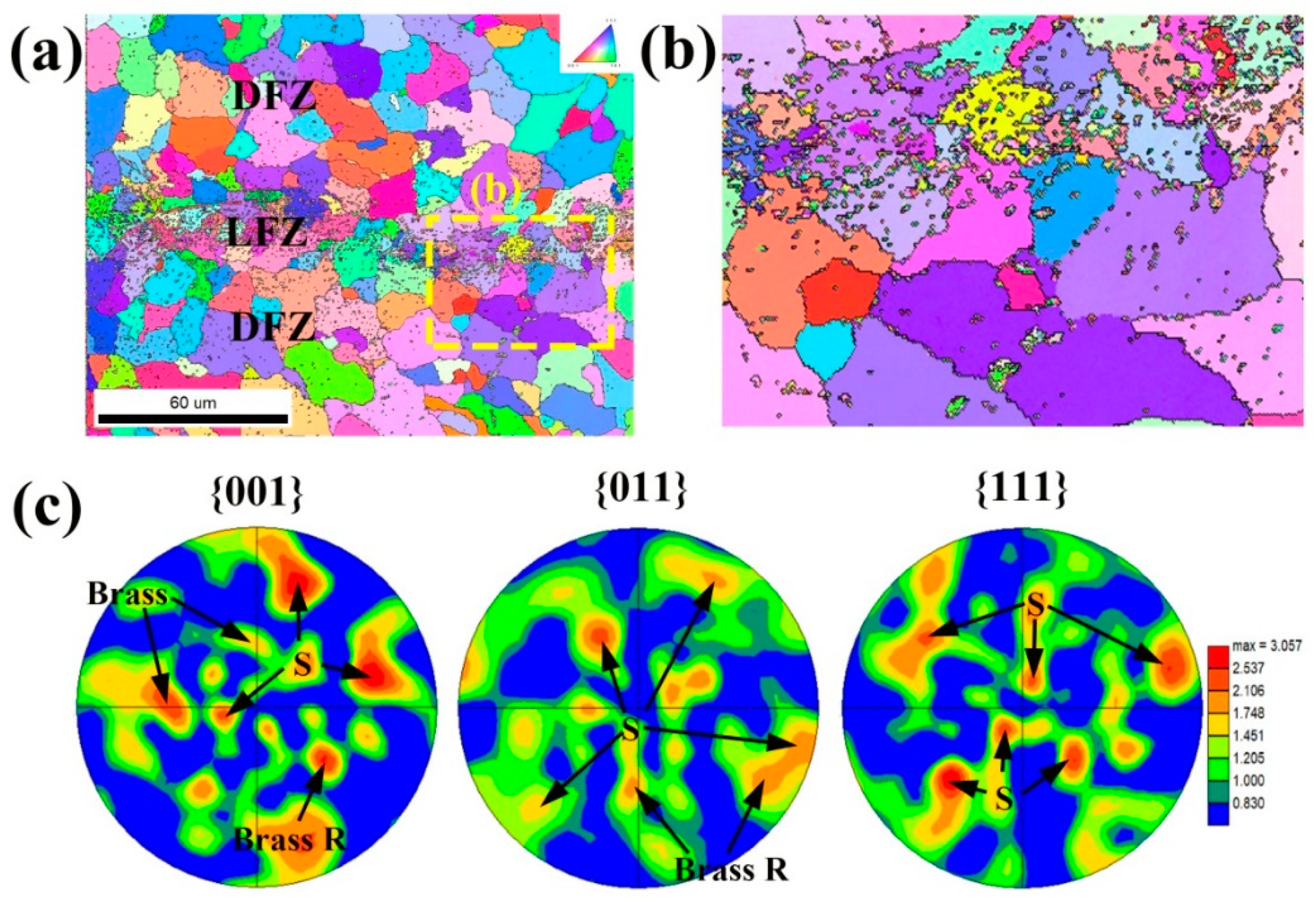
The carbides enriched with Cr and Mn elements are distributed along the flow-line direction for hot-rolled bearing steel. The DFZ has poor corrosion resistance, owing to which more Cr elements formed carbides other than those remaining in the ferrite matrix. Meanwhile, the DFZ has a higher stress concentration compared with the LFZ, while there is no obvious difference of texture between the DFZ and LFZ.
(2)
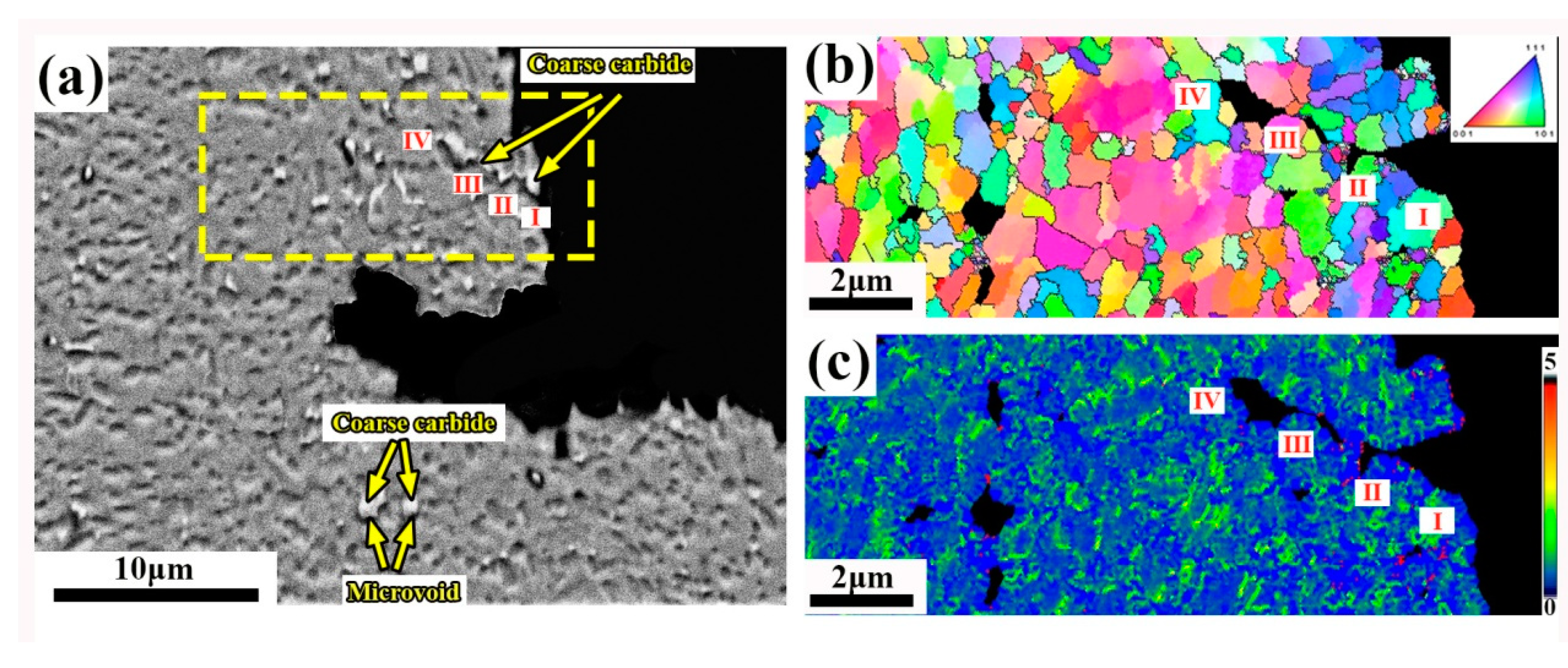
During tensile fracture, the aggregation of coarse carbides promoted the initiation and propagation of cracks in the DFZ. It is also observed that coarse carbides induce the nucleation of microvoids. The adjacent microvoids merge to facilitate the crack propagation process. Furthermore, a secondary crack occurs during the crack propagation process, resulting in a transgranular fracture. The secondary crack can easily spread to adjacent regions, along with the aggregating carbides, and then a new secondary crack is formed.
(3)
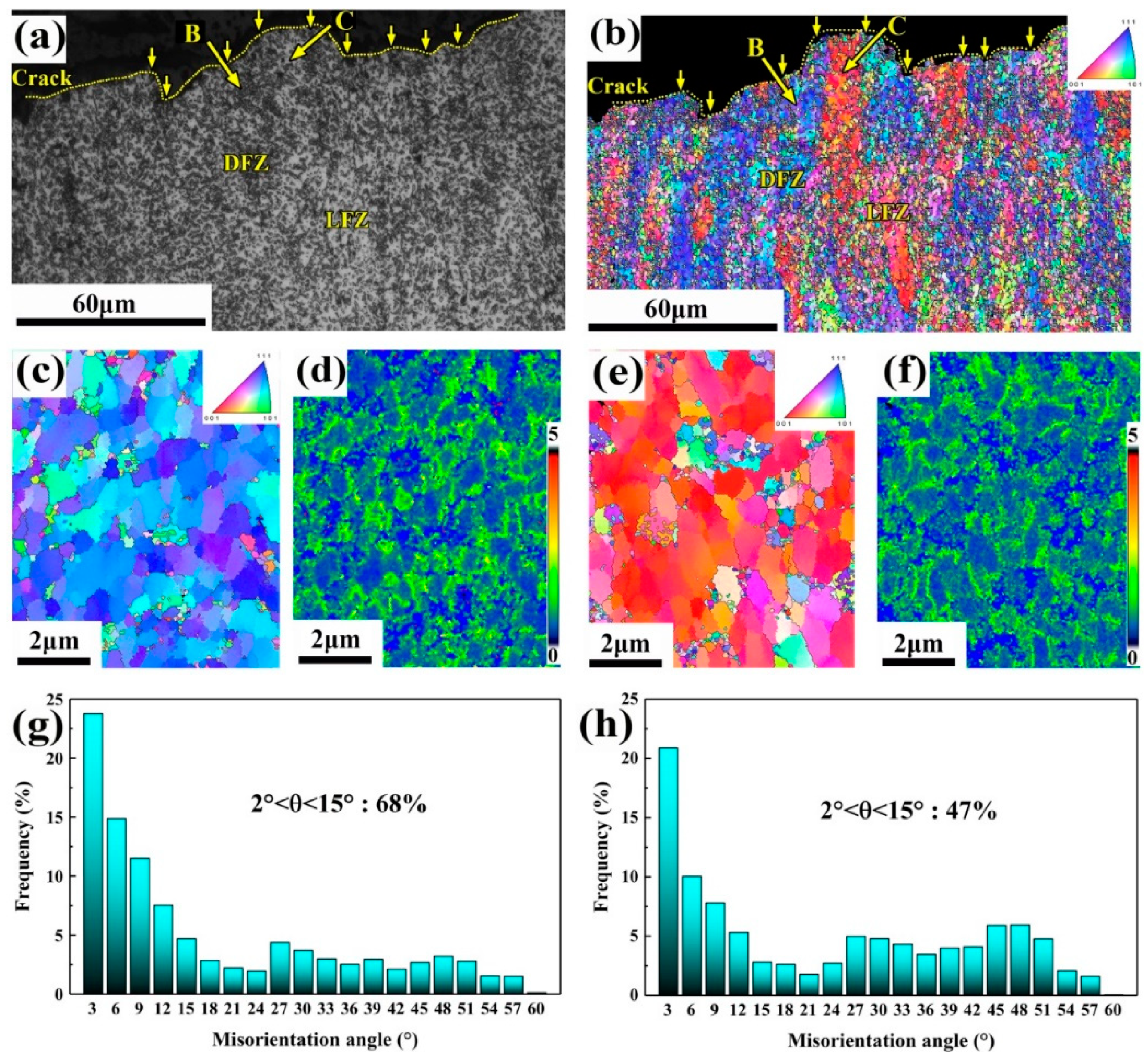
Due to the high stress concentration caused by the aggregation of coarse carbides in the DFZ, the cracks tend to grow rapidly in the DFZ. For the 0° sample, the crack needs to pass through the LFZ and DFZ. Since a crack is difficult to initiate and propagate in the LFZ, the 0° sample will have a large plastic deformation. Owing to the different structure of the DFZ and LFZ, the direction of crack propagation tends to change at the junction of the DFZ and LFZ. Therefore, the 0° sample exhibits higher plasticity. However, for the 90° sample, since the flow lines direction is parallel to the main crack direction, the main crack will grow rapidly along the DFZ. Therefore, the 90° sample shows low plastic deformation, cleavage pattern, and smooth fracture. In addition, the DFZ and LFZ in the flow lines exhibit a strong difference of microstructure and texture after tensile deformation. A higher proportion of low angle grain boundaries indicates that more serious deformation occurs in the DFZ. It is assumed that the aggregation of carbides affect grain deformation during tensile fracture, which results in the delamination of texture in the flow lines.

Author Contributions

Conceptualization, D.Q. and F.W.; methodology, D.Q.; software, C.M.; validation, D.Q., C.M. and F.W.; formal analysis, C.M.; investigation, C.M.; resources, D.Q.; data curation, D.Q.; writing—original draft preparation, C.M.; writing—review and editing, D.Q. and F.W.; visualization, D.Q.; supervision, D.Q.; project administration, D.Q.; funding acquisition, D.Q. All authors have read and agreed to the published version of the manuscript.

Funding

This research was funded by the National Natural Science Foundation of China (No. 51875426), 111 Project (B17034), Innovative Research Team Development Program of Ministry of Education of China (No. IRT_17R83), and Important Science and Technology Innovation Program of Hubei Province (No. 2019AAA001).

Data Availability Statement

The raw/processed data required to reproduce these findings cannot be shared at this time as the data also forms part of an ongoing study.

Acknowledgments

The work was supported by the National Natural Science Foundation of China (No. 51875426), 111 Project (B17034), Innovative Research Team Development Program of Ministry of Education of China (No. IRT_17R83), and Important Science and Technology Innovation Program of Hubei Province (No. 2019AAA001).

Conflicts of Interest

The authors declare no conflict of interest.

References

  1. Liao, S.L.; Zhang, L.L.; Yue, C.X.; Pei, J.B.; Gao, H.J. Hot deformation behaviors and flow stress model of GCr15 bearing steel. J. Cent. South. Univ. Technol. 2008, 15, 575–580. [Google Scholar] [CrossRef]
  2. Guo, J.; Qian, D.S.; Deng, J.D. Grain refinement limit during hot radial ring rolling of as-cast GCr15 steel. J. Mater. Process. Technol. 2016, 213, 151–161. [Google Scholar] [CrossRef]
  3. Peng, N.Q.; Tang, G.B.; Yao, J.; Liu, Z.D. Hot Deformation Behavior of GCr15 Steel. J. Iron. Steel. Res. Int. 2013, 20, 50–56. [Google Scholar] [CrossRef]
  4. Sellars, C.M.; Mctegart, W.J. On the mechanism of hot deformation. Acta. Metall. 1966, 9, 1136–1138. [Google Scholar] [CrossRef]
  5. Krauss, G. Solidification, segregation and banding in carbon and alloy steels. Metall. Mater. Trans. B. 2003, 34, 781–792. [Google Scholar] [CrossRef]
  6. Jiang, H.W.; Song, Y.R.; Wu, Y.C.; Shan, D.B.; Zong, Y.Y. Microstructure evolution and mechanical anisotropy of M50 steel ball bearing rings during multi-stage hot forging. Chin. J. Aeronaut. 2020. [Google Scholar] [CrossRef]
  7. Jiang, H.W.; Song, Y.R.; Wu, Y.C.; Shan, D.B.; Zong, Y.Y. Macrostructure, microstructure and mechanical properties evolution during 8Cr4Mo4V steel roller bearing inner ring forging process. Mat. Sic. Eng. A. 2020, 7981, 140196. [Google Scholar] [CrossRef]
  8. Zhang, H.W.; Wei, Y.L.; Wang, Y.G. Influence of Die Design on Metal Streamline of Aluminium Alloy Close-die Forgings. Light Alloy Fabr. Technol. 2003, 32, 32–34+49. [Google Scholar]
  9. Chu, R.S.; Li, Z.J.; Fan, Y.; Liu, J.G.; Ma, C.W.; Wang, X.H. Cracking and segregation in high-alloy steel 0.4C1.5Mn2Cr0.35Mo1.5Ni produced by thick continuous casting. Heliyon 2019, 5, e01329. [Google Scholar] [CrossRef] [Green Version]
  10. Al-Taameemi, H.A.; Long, H.; Dwyer-Joyce, R.S. Initiation of sub-surface micro-cracks and white etching areas from debonding at non-metallic inclusions in wind turbine gearbox bearing. Wear 2018, 406, 22–32. [Google Scholar] [CrossRef]
  11. Perzynski, K.; Wang, J.T.; Radwanski, K.; Muszka, K.; Madej, L. Identification of critical strains for the random cellular automata finite element failure model based on in-situ tensile test. Mech. Mater. 2019, 133, 154–164. [Google Scholar] [CrossRef]
  12. Guan, J.; Wang, L.Q.; Zhang, Z.Q.; Shi, X.J.; Ma, X.X. Fatigue crack nucleation and propagation at clustered metallic carbides in M50 bearing steel. Tribol. Int. 2018, 119, 165–174. [Google Scholar] [CrossRef]
  13. Wang, F.; Qian, D.S.; Hua, L.; Mao, H.J.; Xie, L.C. Voids healing and carbide refinement of cold rolled M50 bearing steel by electropulsing treatment. Sci. Rep. UK 2019, 9, 11315. [Google Scholar] [CrossRef] [PubMed] [Green Version]
  14. Liu, Z.Y.; Hou, Q.; Li, C.T.; Li, X.G.; Shao, J.M. Correlation between grain boundaries, carbides and stress corrosion cracking of Alloy 690TT in a high temperature caustic solution with lead. Corros. Sci. 2018, 144, 97–106. [Google Scholar] [CrossRef]
  15. Li, C.; Chen, L.Y.; Jiang, T.Z.; Zhang, T.L.; Wang, Y. Process optimization on warm extrusion housing part based on metal flow line. Forging Stamp. Technol. 2017, 42, 143–148. [Google Scholar]
  16. Jiang, H.W.; Wu, Y.C.; Gong, X.D.; Shan, D.B.; Zong, Y.Y. Control of flow lines during the forging process of bearing outer rings with a deviated groove. Int. J. Adv. Manuf. Technol. 2020, 106, 753–764. [Google Scholar] [CrossRef]
  17. Joun, M.S.; Lee, S.W.; Chung, J.H. Finite element analysis of a multi-stage axisymmetric forging process having a spring-attached die for controlling metal flow lines. Int. J. Mach. Tools Manu. 1998, 38, 843–854. [Google Scholar] [CrossRef]
  18. Zhang, Y.; Shan, D.; Xu, F. Flow lines control of disk structure with complex shape in isothermal precision forging. J. Mater. Process. Technol. 2009, 209, 745–753. [Google Scholar] [CrossRef]
  19. Yu, X.L.; Jiang, Z.Y.; Zhao, J.W.; Wei, D.B.; Zhou, J.; Zhou, C.L.; Huang, Q.X. Local strain analysis of the tertiary oxide scale formed on a hot-rolled steel strip via EBSD. Surf. Coat. Technol. 2015, 277, 151–159. [Google Scholar] [CrossRef] [Green Version]
  20. Liu, H.F.; Wei, Y.F.; Tan, C.K.I.; Ardi, D.T.; Tan, D.C.C.; Lee, C.J.J. XRD and EBSD studies of severe shot peening induced martensite transformation and grain refinements in austenitic stainless steel. Mater. Charact. 2020, 168, 110574. [Google Scholar] [CrossRef]
  21. Fu, J.W. Microstructure and corrosion behavior of hot-rolled GCr15 bearing steel. Appl. Phys. A-Mater. 2016, 122, 416. [Google Scholar] [CrossRef]
  22. Li, J.R.; He, T.; Zhang, P.F.; Cheng, L.J.; Wang, L.W. Effect of large-size carbides on the anisotropy of mechanical properties in 11Cr-3Co-3W martensitic heat-resistant steel for turbine high temperature blades in ultra-supercritical power plants. Mater. Charact. 2020, 159, 110025. [Google Scholar] [CrossRef]
  23. Basu, S.; Narasimhan, R. A finite element study of the effects of material characteristics and crack tip constraint on dynamic ductile fracture initiation. J. Mech. Phys. Solids. 1999, 47, 325–350. [Google Scholar] [CrossRef]
  24. Saje, M.; Pan, J.; Needleman, A. Void nucleation effects on shear location in porous plastic solids. Int. J. Fract. 1982, 19, 163–182. [Google Scholar] [CrossRef]
  25. Chu, C.C.; Needleman, A. Void nucleation effects in biaxially stretched sheets. J. Eng. Mater. Technol. 1980, 102, 249–256. [Google Scholar] [CrossRef]
  26. Giang, N.A.; Kuna, M.; Hütter, G. Influence of carbide particles on crack initiation and propagation with competing ductile-brittle transition in ferritic steel. Theor. Appl. Fract. Mech. 2017, 92, 89–98. [Google Scholar] [CrossRef]
  27. Jiang, R.; Bull, D.J.; Evangelou, A.; Harte, A.; Pierron, F.; Sinclair, I.; Preuss, M.; Hu, X.T.; Reed, P.A.S. Strain accumulation and fatigue crack initiation at pores and carbides in a SX superalloy at room temperature. Int. J. Fatigue 2018, 114, 22–33. [Google Scholar] [CrossRef] [Green Version]
  28. Zhu, Q.T.; Li, J.; Shi, C.B.; Yu, W.T. Effect of electroslag remelting on carbides in 8cr13mov martensitic stainless steel. Int. J. Min. Met. Mater. 2015, 22, 1149–1156. [Google Scholar] [CrossRef]
  29. Wang, F.; Qian, D.S.; Hua, L.; Lu, X.H. The effect of prior cold rolling on the carbide dissolution, precipitation and dry wear behaviors of M50 bearing steel. Tribol. Int. 2019, 132, 253–264. [Google Scholar] [CrossRef]
  30. Chen, K.; Wang, J.M.; Shen, Z.; Du, D.H.; Guo, X.L.; Zhang, L.F.; Andresen, P.L. Effect of intergranular carbides on the cracking behavior of cold worked alloy 690 in subcritical and supercritical water. Corros. Sci. 2020, 164, 108313. [Google Scholar] [CrossRef]
  31. Wang, C.; Tan, X.; Liu, E.; Tor, S. Process parameter optimization and mechanical properties for additively manufactured stainless steel 316L parts by selective electron beam melting. Mater. Des. 2018, 147, 157–166. [Google Scholar] [CrossRef]
  32. Serrano, M.; Hernández-Mayoral, M.; García-Junceda, A. Microstructural anisotropy effect on the mechanical properties of a 14Cr ODS steel. J. Nucl. Mater. 2012, 428, 103–109. [Google Scholar] [CrossRef]
  33. Jebaraj, A.V.; Kumar, L.; Deepak, C.K. Investigations on anisotropy behavior of duplex stainless steel AISI 2205 for optimum weld properties. Procedia Eng. 2017, 173, 883–890. [Google Scholar] [CrossRef]
Figure 1. (a) Schematic diagram of the sampling process; (b) the details of the dimension of the samples used in tensile testing; (c) the diagram of the etched surface of the flow line sample.
Metals 11 00456 g001
Figure 2. OM images of the flow lines in hot-rolled bearing steel: (a) image showing the DFZ and LFZ; (b) magnified image of the DFZ; (c) magnified image of the LFZ.
Metals 11 00456 g002
Figure 3. EPMA mapping the flow lines in hot-rolled bearing steel: (a) secondary electron image of the flow lines; (bf) distribution of the main elements.
Metals 11 00456 g003
Figure 4. SEM images of the DFZ and LFZ in hot-rolled bearing steel: (a) the DFZ etched for 3 min; (b) the LFZ etched for 3 min; (c) the DFZ etched for 6 min; (d) the LFZ etched for 6 min.
Metals 11 00456 g004
Figure 5. Distribution of carbide diameter in the DFZ and LFZ.
Metals 11 00456 g005
Figure 6. The microstructure and kernel average misorientation (KAM) of the flow lines: (a) microstructure image; (b) KAM image; ((c,d)) the zone marked by a yellow box in (a,b).
Metals 11 00456 g006
Figure 7. Texture of the flow lines: (a) <100> inverse pole figure (IPF); (b) the magnified zone in (a); (c) {001}, {110}, and {111} pole figure.
Metals 11 00456 g007
Figure 8. The tensile properties of the hot-rolled bearing steel in the directions 0° and 90°: (a) Engineering stress-strain curve; (b) average plastic elongation and section shrinkage.
Metals 11 00456 g008
Figure 9. (a,b) Images of the fracture surfaces in 0° and 90° samples after the tensile test; (c,d) images of the magnified microscopic fracture morphology in 0°and 90° samples.
Metals 11 00456 g009
Figure 10. The OM images of the fractured samples in the two directions after the tensile tests: (a) 0° sample; (b) 90° sample. Note that the yellow arrow refers to the crack propagation direction.
Metals 11 00456 g010
Figure 11. The OM and EBSD results of the selected region: (a) the OM image; (b) the IPF image; the detailed IPF at (c) regions B and (e) region C; the detailed KAM image at (d) region B and (f) region C; the distribution of misorientation angle of (g) region B and (h) region C.
Metals 11 00456 g011
Figure 12. (a) SEM image of the typical tensile crack in the 0° sample; (b,c) IPF and KAM images of the secondary crack marked by the yellow box in (a).
Metals 11 00456 g012
Figure 13. (a) The local topography, (b) the Backscatter image, and (c) the secondary electron image showing the secondary crack of the 90° sample.
Metals 11 00456 g013
Figure 14. Schematic illustrations showing the effect of the flow lines on the mechanical anisotropy: (a) 0° sample; (b) 90° sample.
Metals 11 00456 g014
Table 1. Chemical composition of AISI 52,100 bearing steel [wt. %].
CCrMnSiPSMoAlCoCu
1.0001.5510.4580.2380.0060.0020.0230.0120.0150.065
Publisher’s Note: MDPI stays neutral with regard to jurisdictional claims in published maps and institutional affiliations.

