
Microstructure Evolution and Mechanical Property Response of 3D-Printed Scalmalloy with Different Heat-Treatment Times at 325 °C


Abstract
:1. Introduction
2. Experimental Procedure
3. Results and Discussion
3.1. Microstructure Observations
3.2. Mechanical Properties
4. Conclusions
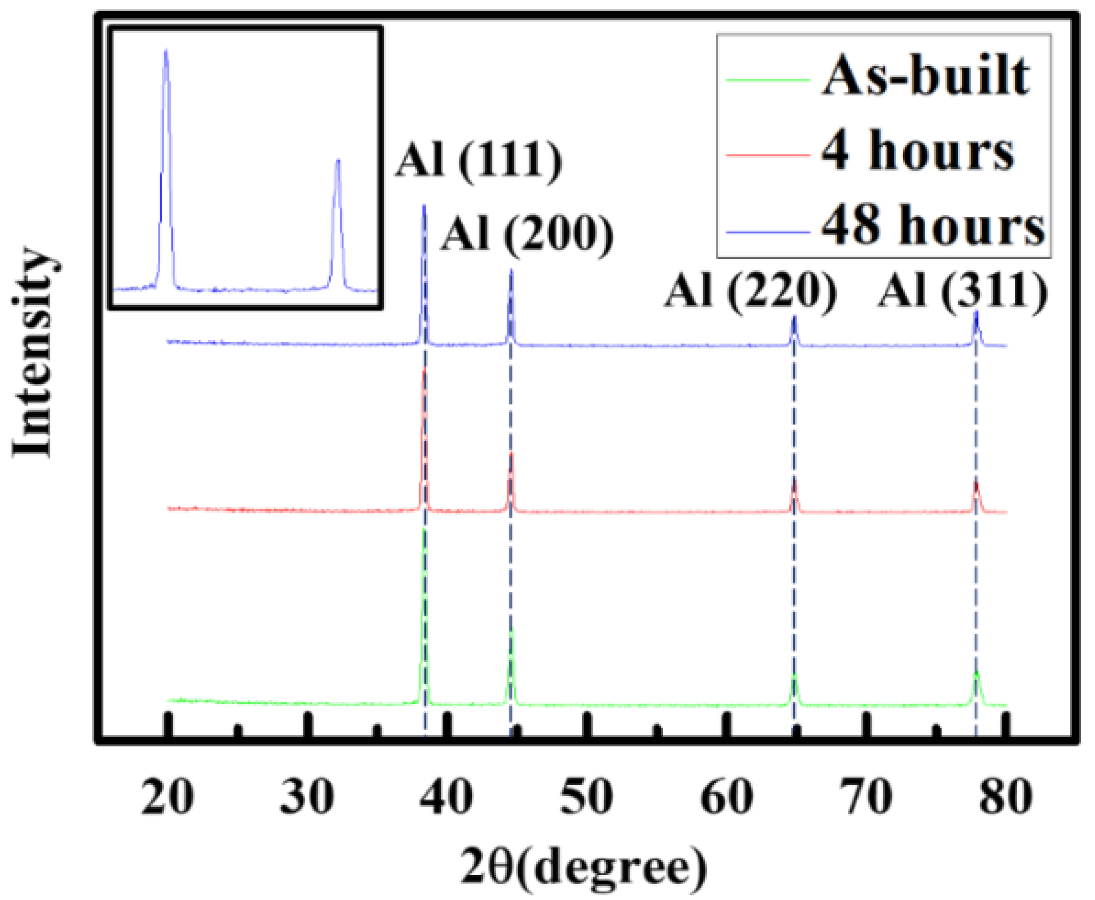
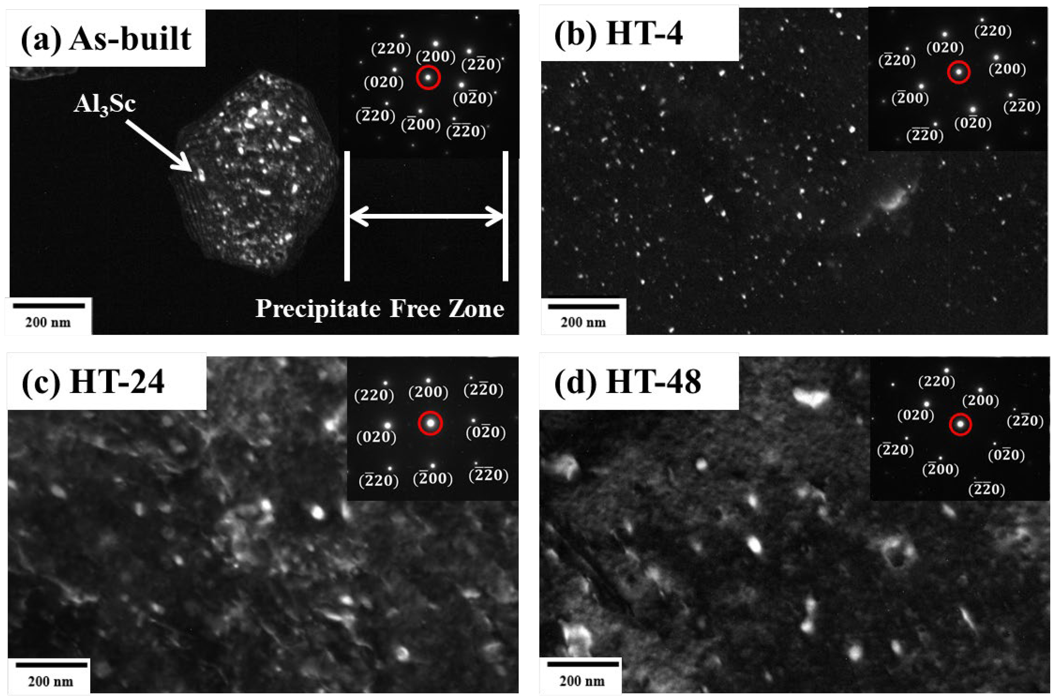
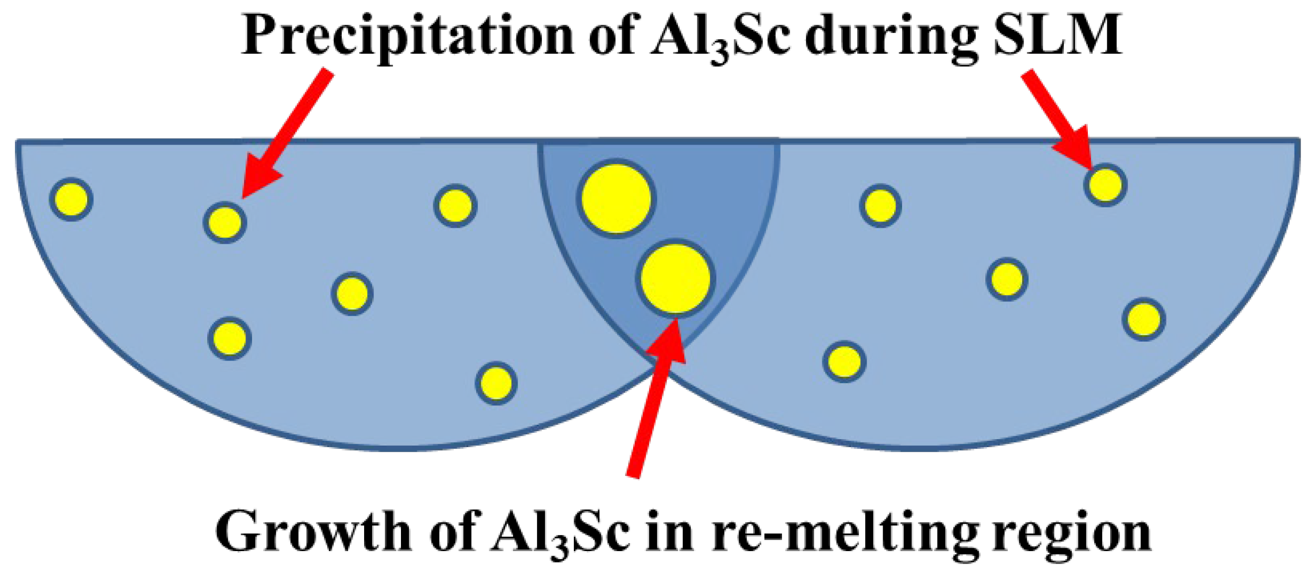
- After heat-treatment, there is no obvious grain size change or phase transformation. On the other hand, the size and distribution of precipitates are greatly affected by the heat-treatment parameter. Before heat-treatment, the distribution of precipitates was non-uniform, and thus there were regions which, found to be free of precipitates, are called the precipitate free zones (PFZ). After proper heat-treatment, the Al3Sc precipitated uniformly and grew (from 12.0 nm to 20.0 nm) with increasing heat-treatment time.
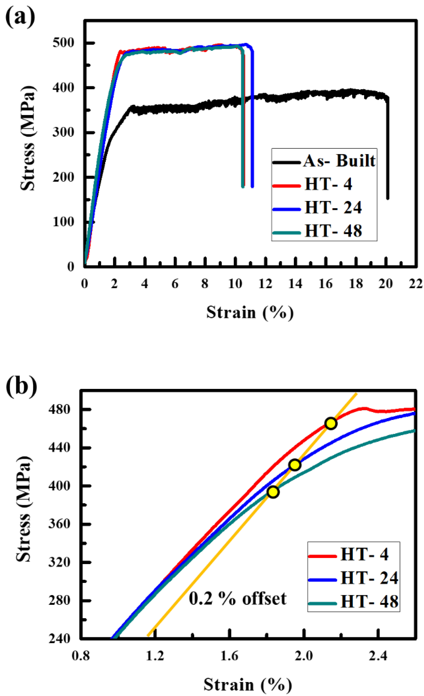
- Since the region free of precipitates was no longer observed in the samples after 4 h of heat-treatment, the precipitate free zone seemed to be eliminated. The mechanical properties of 3D-printed Scalmalloy samples, especially the yield stress, greatly improved from 286.9 MPa to 455.8 MPa. After that, the yield stress is decreased with increasing heat-treatment time.
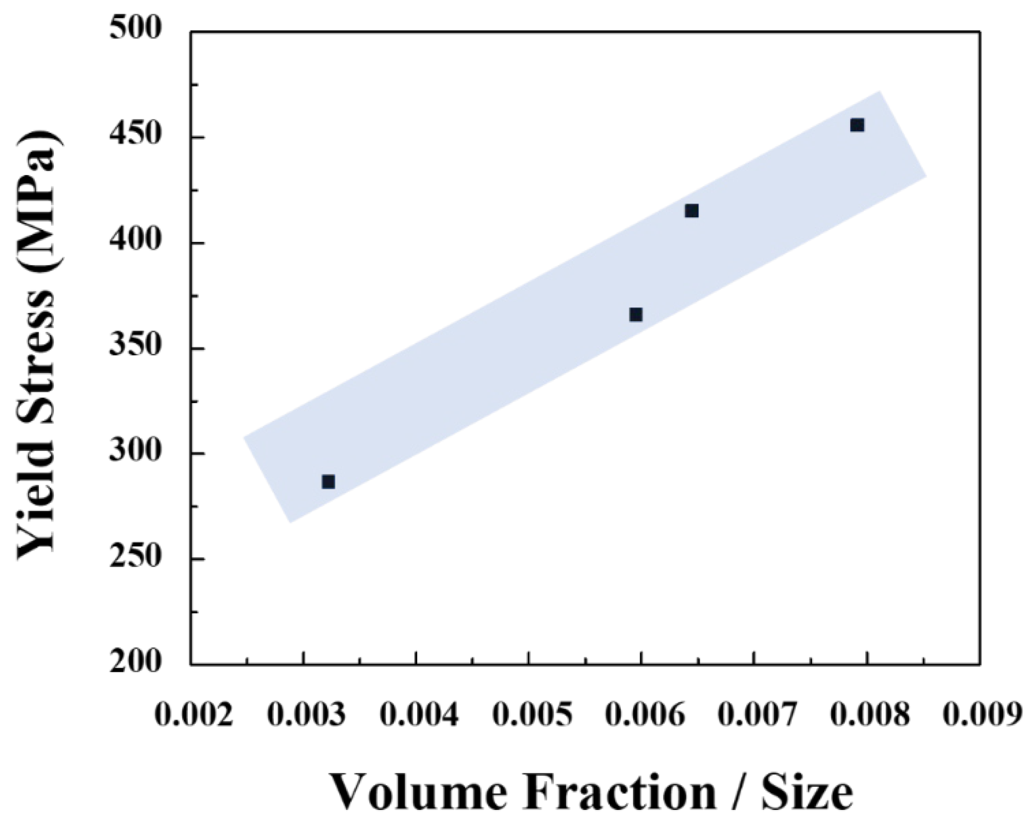
- According to the precipitation strengthening model, the yield stress increases with decreasing precipitate spacing (Orowan’s law). However, due to the presence of the precipitate free zone, it was hard to measure the precipitate spacing of the as-built sample and this could result in a miscalculation. Thus, in this study, we found that the precipitation strengthening effects on mechanical properties can be described as the ratio of volume fraction to size when the precipitate spacing is hard to measured.
Author Contributions
Funding
Institutional Review Board Statement
Informed Consent Statement
Data Availability Statement
Acknowledgments
Conflicts of Interest
References
- Spierings, A.B.; Dawson, K.; Kern, K.; Palm, F.; Wegener, K. SLM-processed Sc- and Zr- modified Al-Mg alloy: Mechanical properties and microstructural effects of heat treatment. Mater. Sci. Eng. A 2017, 701, 264–273. [Google Scholar] [CrossRef]
- Zhou, J.; Shrotriya, P.; Soboyejo, W.O. On the deformation of aluminum lattice block structures: From struts to structures. Mech. Mater. 2004, 36, 723–737. [Google Scholar] [CrossRef]
- Yeong, W.-Y.; Chua, C.-K.; Leong, K.-F.; Chandrasekaran, M. Rapid prototyping in tissue engineering: Challenges and potential. Trends Biotechnol. 2004, 22, 643–652. [Google Scholar] [CrossRef]
- Wang, X.; Xu, S.; Zhou, S.; Xu, W.; Leary, M.; Choong, P.; Qian, M.; Brandt, M.; Xie, Y.M. Topological design and additive manufacturing of porous metals for bone scaffolds and orthopaedic implants: A review. Biomaterials 2016, 83, 127–141. [Google Scholar] [CrossRef]
- Khairallah, S.A.; Anderson, A.T.; Rubenchik, A.; King, W.E. Laser powder-bed fusion additive manufacturing: Physics of complex melt flow and formation mechanisms of pores, spatter, and denudation zones. Acta Mater. 2016, 108, 36–45. [Google Scholar] [CrossRef] [Green Version]
- Herzog, D.; Seyda, V.; Wycisk, E.; Emmelmann, C. Additive manufacturing of metals. Acta Mater. 2016, 117, 371–392. [Google Scholar] [CrossRef]
- Shuai, C.; Yang, Y.; Feng, P.; Peng, S.; Guo, W.; Min, A.; Gao, C. A multi-scale porous scaffold fabricated by a combined additive manufacturing and chemical etching process. Int. J. Bioprint. 2018, 4, 133. [Google Scholar] [CrossRef] [PubMed]
- Yang, Y.; Wang, G.; Liang, H.; Gao, C.; Peng, S.; Shen, L.; Shuai, C. Additive manufacturing of bone scaffolds. Int. J. Bioprint. 2019, 5, 148. [Google Scholar] [CrossRef] [PubMed]
- Kolan, K.; Li, J.; Roberts, S.; Semon, J.A.; Park, J.; Day, D.E.; Leu, M.C. Near-field electrospinning of a polymer/bioactive glass composite to fabricate 3D biomimetic structures. Int. J. Bioprint. 2019, 5, 163. [Google Scholar] [CrossRef] [PubMed]
- Shie, M.-Y.; Fang, H.-Y.; Lin, Y.-H.; Lee, A.K.-X.; Yu, J.; Chen, Y.-W. Application of piezoelectric cells printing on three-dimensional porous bioceramic scaffold for bone regeneration. Int. J. Bioprint. 2019, 5, 210. [Google Scholar] [CrossRef] [PubMed]
- Chua, C.K.; Leong, K.F. 3D Printing and Additive Manufacturing: Principles and Applications, 5th ed.; World Scientific: Singapore, 2017. [Google Scholar]
- Chua, C.K.; Leong, K.F.; Lim, C.S. Rapid Prototyping: Principles and Applications; World Scientific: Singapore, 2010. [Google Scholar]
- Gibson, I.; Rosen, D.W.; Stucker, B. Additive Manufacturing Technologies; Springer: Berlin/Heidelberg, Germany, 2010. [Google Scholar]
- Liu, Y.J.; Li, S.J.; Wang, H.L.; Hou, W.T.; Hao, Y.L.; Yang, R.; Sercombe, T.B.; Zhang, L.C. Microstructure, defects and mechanical behavior of beta-type titanium porous structures manufactured by electron beam melting and selective laser melting. Acta Mater. 2016, 113, 56–67. [Google Scholar] [CrossRef] [Green Version]
- Zhao, X.L.; Li, S.J.; Zhang, M.; Liu, Y.D.; Sercombe, T.B.; Wang, S.G.; Hao, Y.L.; Yang, R.; Murr, L.E. Comparison of the microstructures and mechanical properties of Ti–6Al–4V fabricated by selective laser melting and electron beam melting. Mater. Des. 2016, 95, 21–31. [Google Scholar] [CrossRef]
- Sudarmadji, N.; Tan, J.Y.; Leong, K.F.; Chua, C.K.; Loh, Y.T. Investigation of the mechanical properties and porosity relationships in selective laser-sintered polyhedral for functionally graded scaffolds. Acta Biomater. 2011, 7, 530–537. [Google Scholar] [CrossRef] [PubMed]
- Murr, L.E. Open-cellular metal implant design and fabrication for biomechanical compatibility with bone using electron beam melting. J. Mech. Behav. Biomed. Mater. 2017, 76, 164–177. [Google Scholar] [CrossRef] [PubMed]
- Chen, S.Y.; Kuo, C.N.; Su, Y.L.; Huang, J.C.; Wu, Y.C.; Lin, Y.H.; Chung, Y.C.; Ng, C.H. Microstructure and fracture properties of open-cell porous Ti-6Al-4V with high porosity fabricated by electron beam melting. Mater. Charact. 2018, 138, 255–262. [Google Scholar] [CrossRef]
- Kuo, C.N.; Chua, C.K.; Peng, P.C.; Chen, Y.W.; Sing, S.L.; Huang, S.; Su, Y.L. Microstructure evolution and mechanical property response via 3D printing parameter development of Al–Sc alloy. Virtual Phys. Prototyp. 2020, 15, 120–129. [Google Scholar] [CrossRef]
- Schmidtke, K.; Palm, F.; Hawkins, A.; Emmelmann, C. Process and Mechanical Properties: Applicability of a Scandium modified Al-alloy for Laser Additive Manufacturing. Phys. Procedia 2011, 12, 369–374. [Google Scholar] [CrossRef] [Green Version]
- Jägle, E.A.; Lu, L.; Wu, L.; Raabe, D. Alloy Design for Additive Manufacturing; Max-Planck-Institut: Nijmegen, Germany, 2016; pp. 1–43. [Google Scholar]
- Wang, M.; Li, R.; Yuan, T.; Chen, C.; Zhou, L.; Chen, H.; Zhang, M.; Xie, S. Microstructures and mechanical property of AlMgScZrMn—A comparison between selective laser melting, spark plasma sintering and cast. Mater. Sci. Eng. A 2019, 756, 354–364. [Google Scholar] [CrossRef]
- Spierings, A.B.; Dawson, K.; Voegtlin, M.; Palm, F.; Uggowitzer, P.J. Microstructure and mechanical properties of as-processed scandium-modified aluminium using selective laser melting. Cirp Ann. 2016, 65, 213–216. [Google Scholar] [CrossRef]
- Spierings, A.B.; Dawson, K.; Heeling, T.; Uggowitzer, P.J.; Schäublin, R.; Palm, F.; Wegener, K. Microstructural features of Sc- and Zr-modified Al-Mg alloys processed by selective laser melting. Mater. Des. 2017, 115, 52–63. [Google Scholar] [CrossRef]
- Li, R.; Wang, M.; Yuan, T.; Song, B.; Chen, C.; Zhou, K.; Cao, P. Selective laser melting of a novel Sc and Zr modified Al-6.2 Mg alloy: Processing, microstructure, and properties. Powder Technol. 2017, 319, 117–128. [Google Scholar] [CrossRef]
- Spierings, A.B.; Dawson, K.; Uggowitzer, P.J.; Wegener, K. Influence of SLM scan-speed on microstructure, precipitation of Al3Sc particles and mechanical properties in Sc- and Zr-modified Al-Mg alloys. Mater. Des. 2018, 140, 134–143. [Google Scholar] [CrossRef]
- Best, J.P.; Maeder, X.; Michler, J.; Spierings, A.B. Mechanical Anisotropy Investigated in theComplex SLM-Processed Sc- and Zr-Modified Al–Mg Alloy Microstructure. Adv. Eng. Mater. 2019, 21, 1801113. [Google Scholar] [CrossRef]
- Koutny, D.; Skulina, D.; Pantělejev, L.; Paloušek, D.; Lenczowski, B.; Palm, F.; Nick, A. Processing of Al-Sc aluminum alloy using SLM technology. Procedia Cirp 2018, 74, 44–48. [Google Scholar] [CrossRef]
- Churyumov, A.Y.; Pozdniakov, A.V.; Prosviryakov, A.S.; Loginova, I.S.; Daubarayte, D.K.; Ryabov, D.K.; Korolev, V.A.; Solonin, A.N.; Pavlov, M.D.; Valchuk, S.V. Microstructure and mechanical properties of a novel selective laser melted Al-Mg alloy with low Sc content. Mater. Res. Express 2019, 6, 126595. [Google Scholar] [CrossRef]
- Mikhaylovskaya, A.V.; Mochugovskiy, A.G.; Levchenko, V.S.; Tabachkova, N.Y.; Mufalo, W.; Portnoy, V.K. Precipitation behavior of L12 Al3Zr phase in Al-Mg-Zr alloy. Mater. Charact. 2018, 139, 30–37. [Google Scholar] [CrossRef]
- Andersen, S.J.; Marioara, B.H.C.D. Quantification of small, convex particles by TEM. Ultramicroscopy 2008, 108, 750–762. [Google Scholar] [CrossRef]
- Wosik, J.; Dubiel, B.; Kruk, A.; Penkalla, H.-J.; Schubert, F.; Czyrska-Filemonowicz, A. Stereological estimation of microstructural parameters of nickel-based superalloy Waspaloy using TEM methods. Mater. Charact. 2001, 46, 119–123. [Google Scholar] [CrossRef]
- Ocenasek, V.; Slamova, M. Resistance to recrystallization due to Sc and Zr addition to Al–Mg alloys. Mater. Charact. 2001, 47, 157–162. [Google Scholar] [CrossRef]


| Laser Power (W) | Scan Speed (mm/s) | Hatch Distance (mm) | Layer Thickness (mm) | E = P/vht (J/mm3) |
|---|---|---|---|---|
| 200 | 500 | 0.05 | 0.03 | 266.7 |
| Sample | Micron-Sized Grains | Submicron-Sized Grains | Average Grain Size (µm) | ||
|---|---|---|---|---|---|
| Grain Size (µm) | Volume Fraction (%) | Grain Size (µm) | Volume Fraction (%) | ||
| As-Built | 2.2 ± 0.3 | 51.0 ± 12.1 | 0.4 ± 0.0 | 49.0 ± 12.1 | 1.30 |
| HT-4 | 1.8 ± 0.1 | 54.5 ± 8.1 | 0.4 ± 0.0 | 45.5 ± 8.1 | 1.19 |
| HT-24 | 1.8 ± 0.0 | 52.0 ± 7.8 | 0.4 ± 0.0 | 48.0 ± 7.8 | 1.15 |
| HT-48 | 2.1 ± 0.1 | 52.5 ± 6.3 | 0.4 ± 0.0 | 47.5 ± 6.3 | 1.28 |
| Sample | Al3Sc Spacing (nm) | Al3Sc Size (nm) | Al3Sc Volume Fraction (%) | |
|---|---|---|---|---|
| As-Built | 14.9 ± 0.8 | 0.048 ± 0.003 | 0.00322 | |
| HT-4 | 21.0 ± 2.5 | 12.0 ± 0.1 | 0.095 ± 0.003 | 0.00792 |
| HT-24 | 37.4 ± 3.3 | 18.3 ± 1.0 | 0.118 ± 0.008 | 0.00645 |
| HT-48 | 45.6 ± 0.7 | 20.0 ± 0.3 | 0.119 ± 0.006 | 0.00595 |
| Sample | Yield Stress (0.2% Offset) (MPa) | Elongation (%) |
|---|---|---|
| As-Built | 286.9 ± 6.2 | 18.4 ± 2.8 |
| HT-4 | 455.8 ± 8.9 | 10.3 ± 0.2 |
| HT-24 | 415.2 ± 22.4 | 11.0 ± 0.1 |
| HT-48 | 365.9 ± 22.8 | 10.0 ± 0.5 |
Publisher’s Note: MDPI stays neutral with regard to jurisdictional claims in published maps and institutional affiliations. |
© 2021 by the authors. Licensee MDPI, Basel, Switzerland. This article is an open access article distributed under the terms and conditions of the Creative Commons Attribution (CC BY) license (http://creativecommons.org/licenses/by/4.0/).
Share and Cite
Kuo, C.N.; Peng, P.C.; Liu, D.H.; Chao, C.Y. Microstructure Evolution and Mechanical Property Response of 3D-Printed Scalmalloy with Different Heat-Treatment Times at 325 °C. Metals 2021, 11, 555. https://doi.org/10.3390/met11040555
Kuo CN, Peng PC, Liu DH, Chao CY. Microstructure Evolution and Mechanical Property Response of 3D-Printed Scalmalloy with Different Heat-Treatment Times at 325 °C. Metals. 2021; 11(4):555. https://doi.org/10.3390/met11040555
Chicago/Turabian StyleKuo, C. N., P. C. Peng, D. H. Liu, and C. Y. Chao. 2021. "Microstructure Evolution and Mechanical Property Response of 3D-Printed Scalmalloy with Different Heat-Treatment Times at 325 °C" Metals 11, no. 4: 555. https://doi.org/10.3390/met11040555