
Springback Analysis of Flexible Stretch Bending of Multi-Point Roller Dies Process for Y-Profile under Different Process Parameters


Abstract
:1. Introduction
2. Materials and Methods
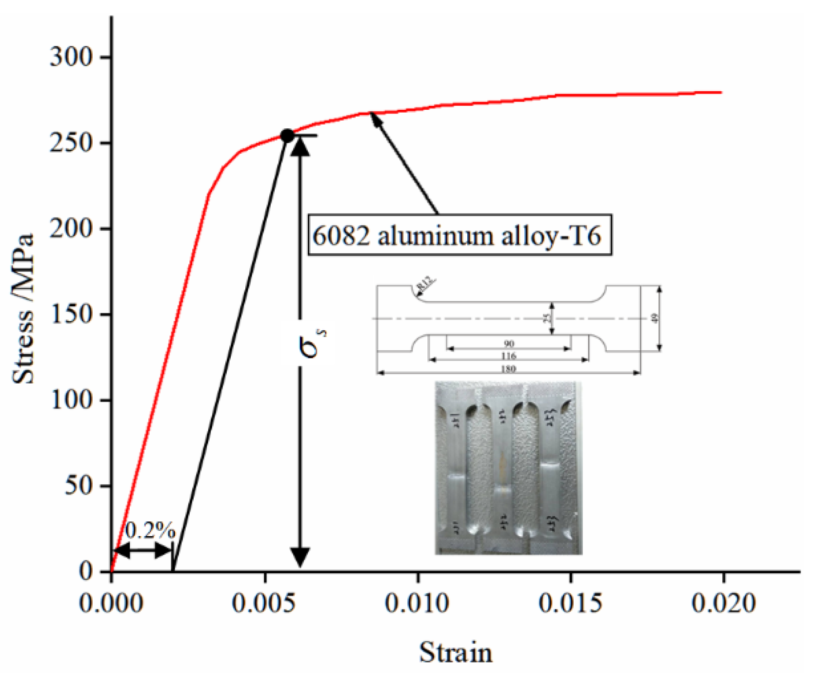
2.1. Material Model
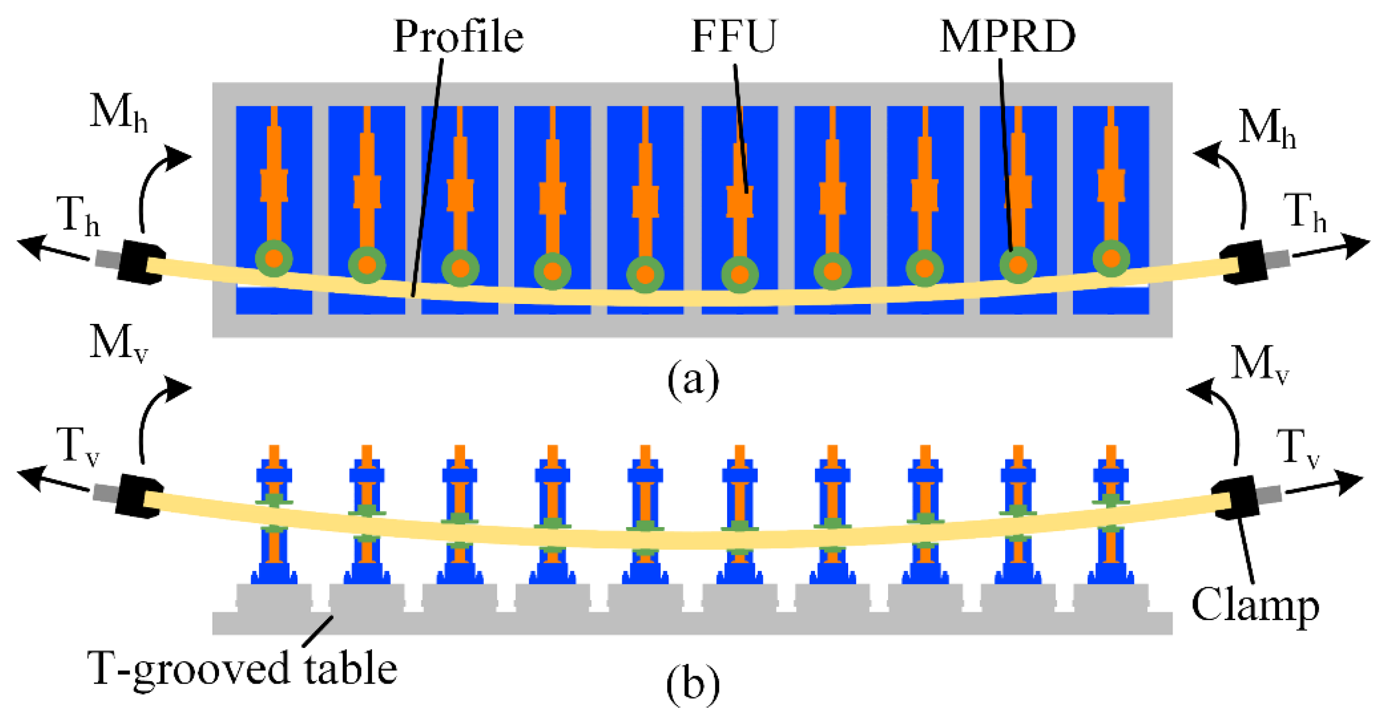
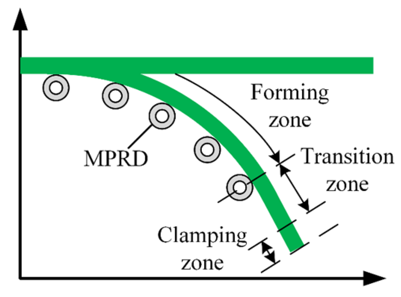
2.2. Forming Method
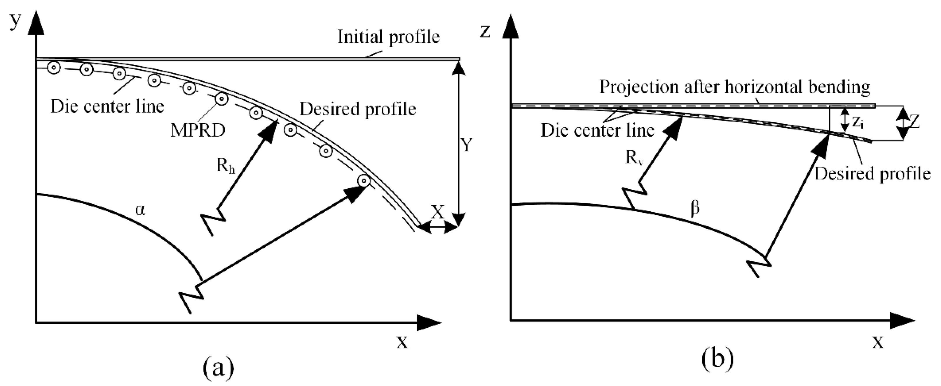
2.3. Trajectory Design
3. Numerical Simulation
3.1. Finite Element Model
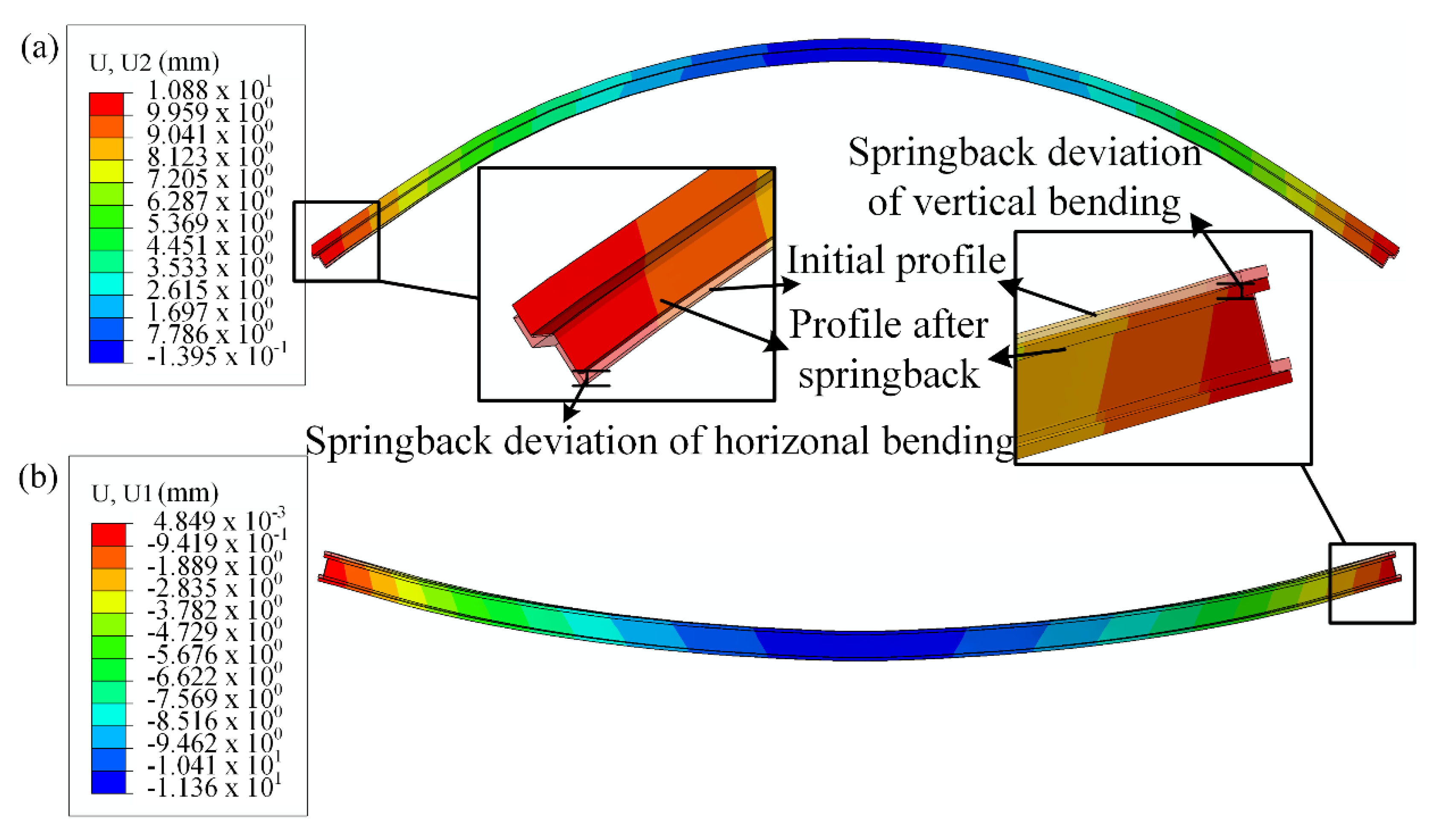
3.2. Characterization of Springback
4. Results and Discussion
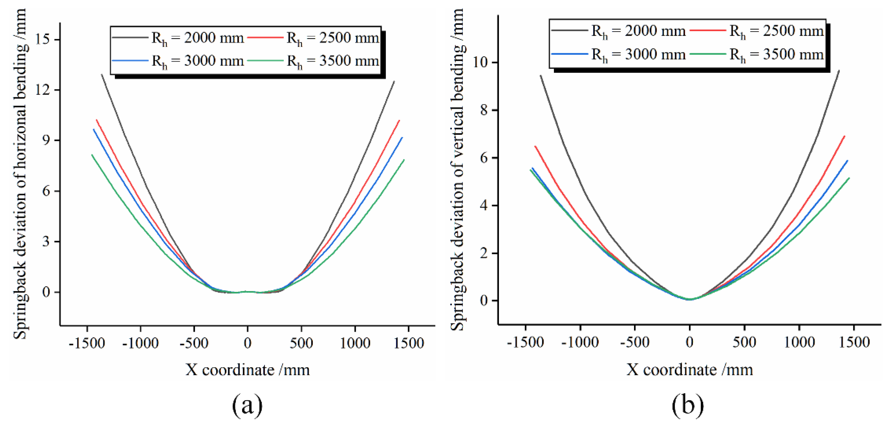
4.1. Influence of Horizontal Bending Radius on Springback
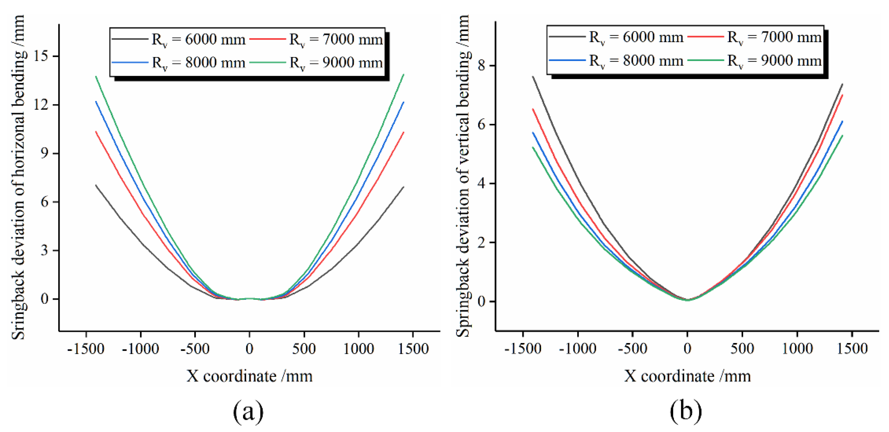
4.2. Influence of Vertical Bending Radius on Springback
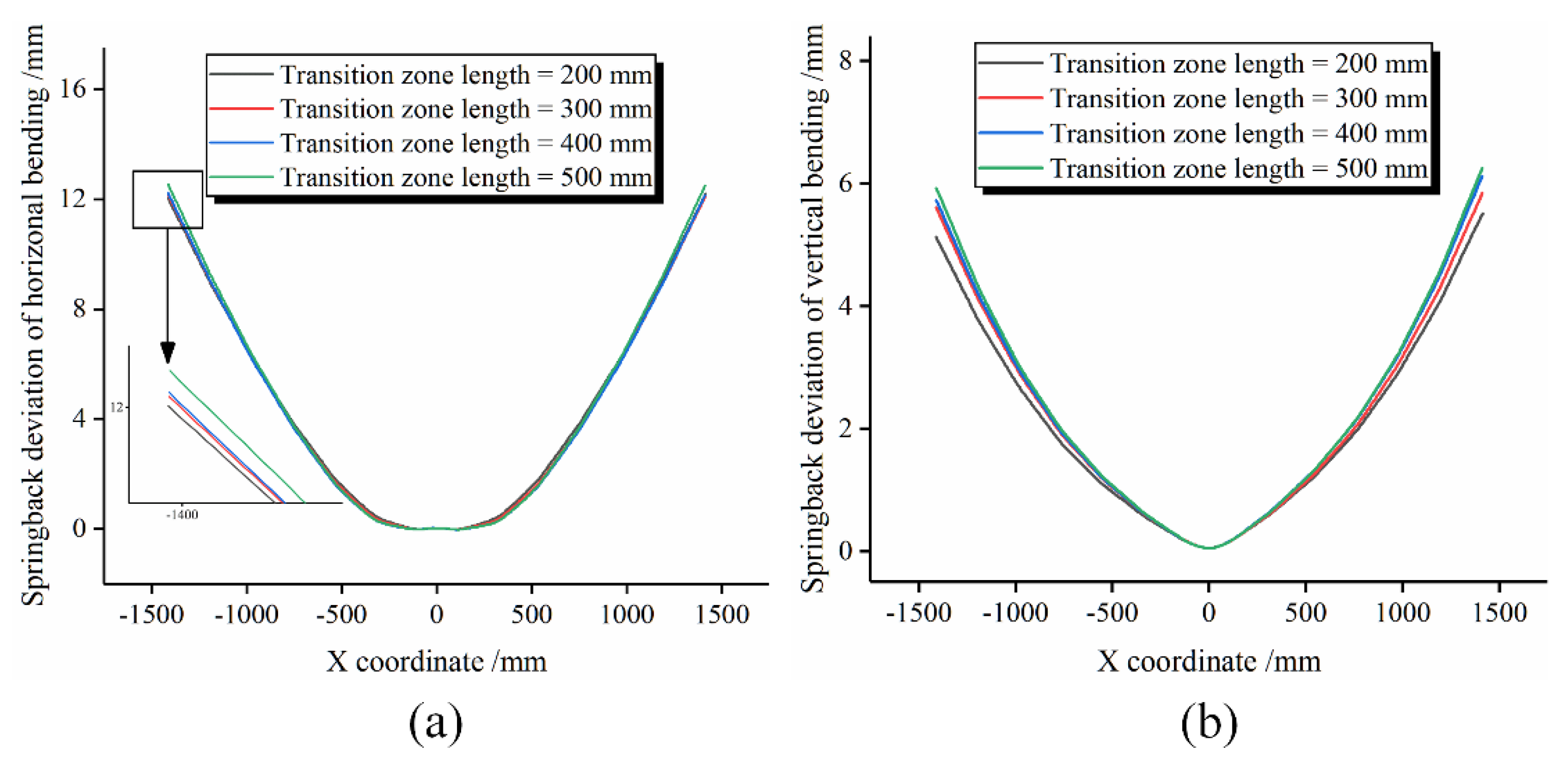
4.3. Influence of Transition Zone Length on Springback
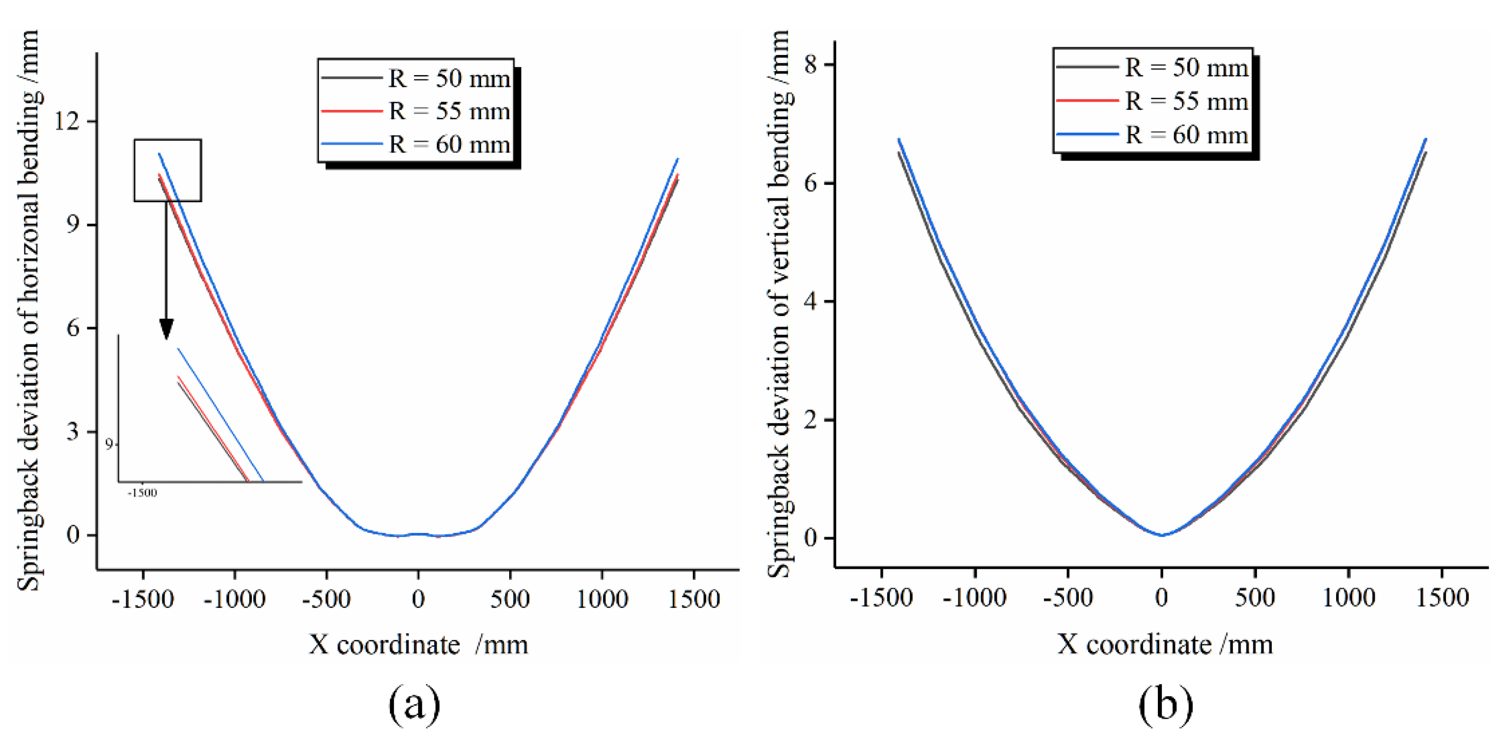
4.4. Influence of Radius of Roller Dies on Springback
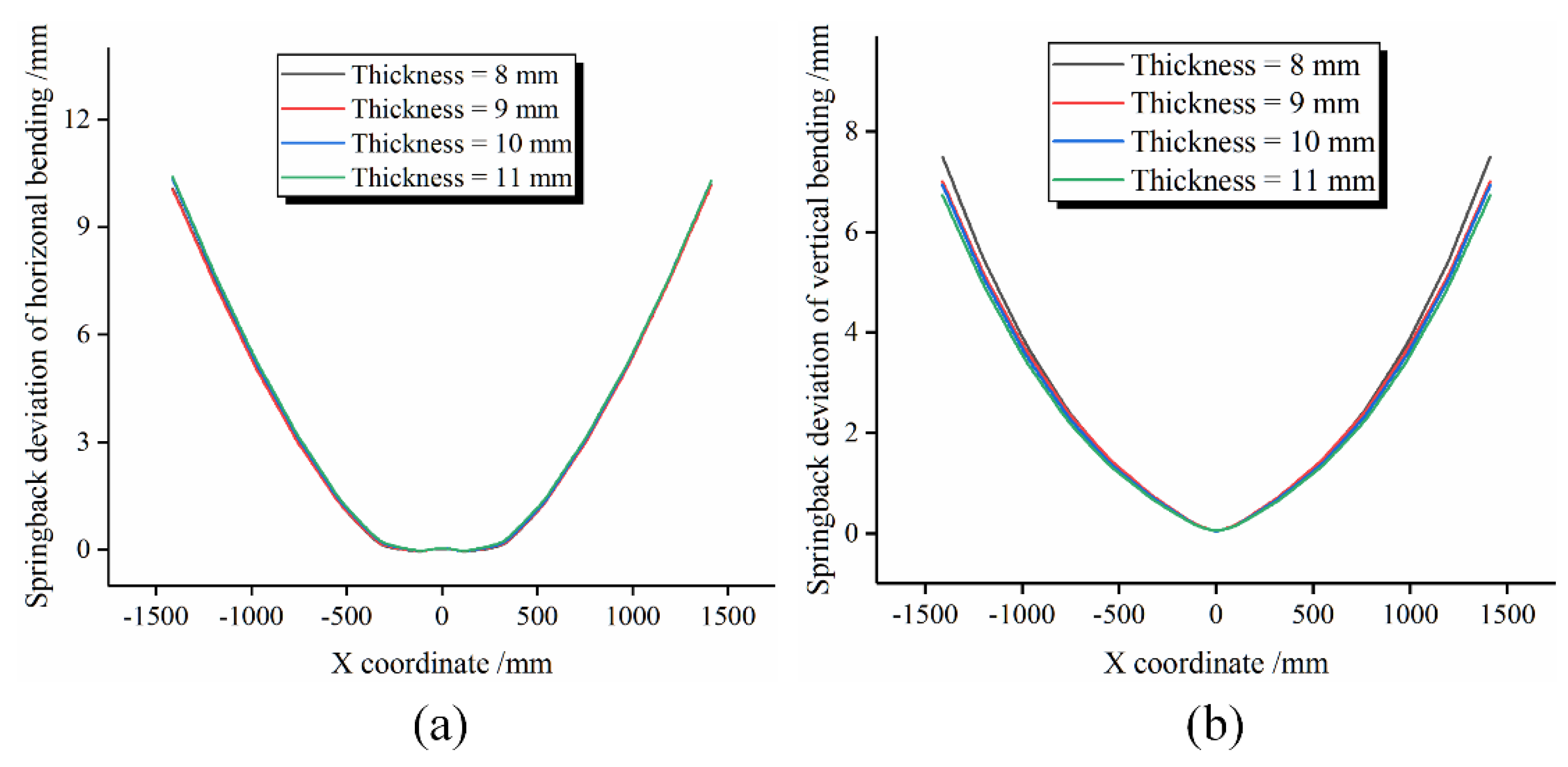
4.5. Influence of Wall Thickness of Profile on Springback
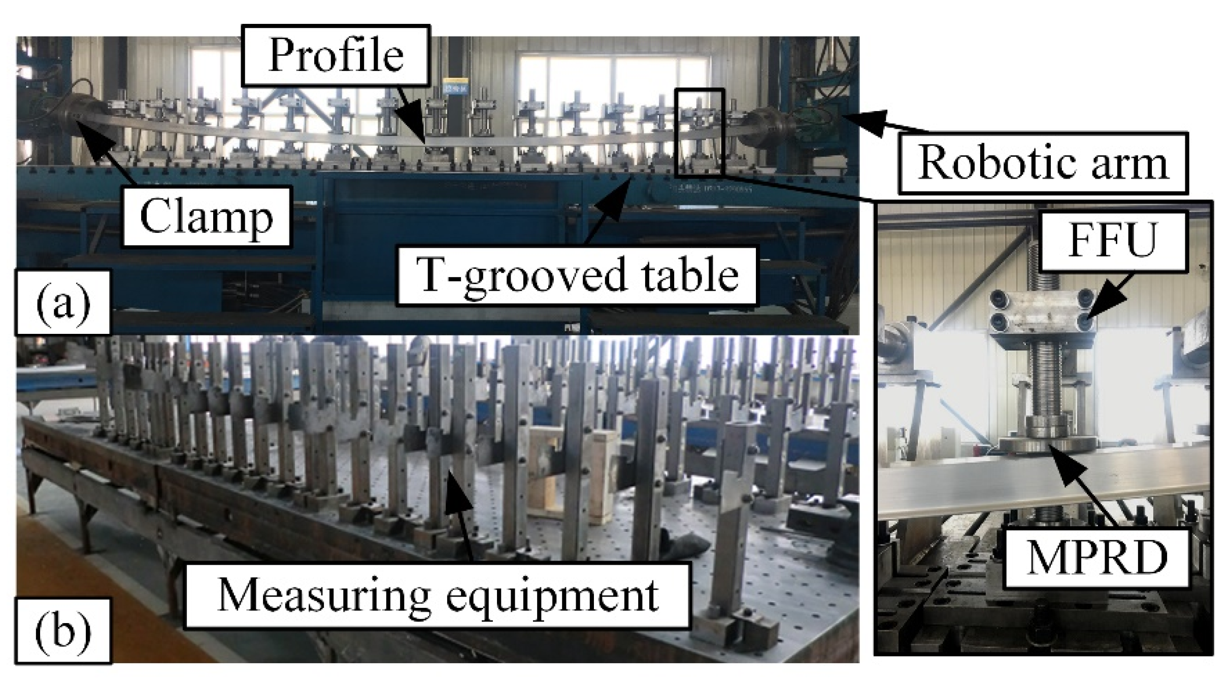
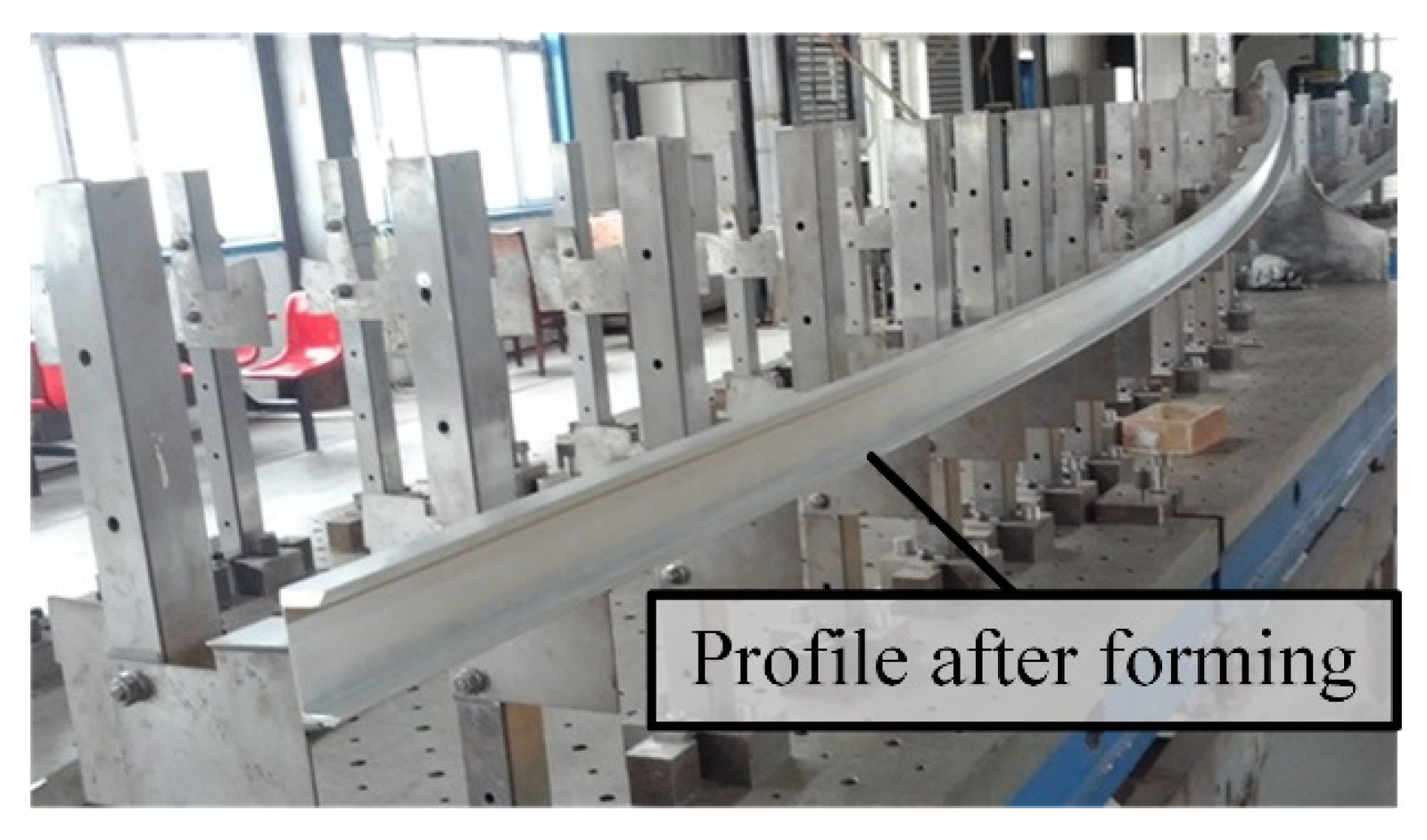
5. Experiments
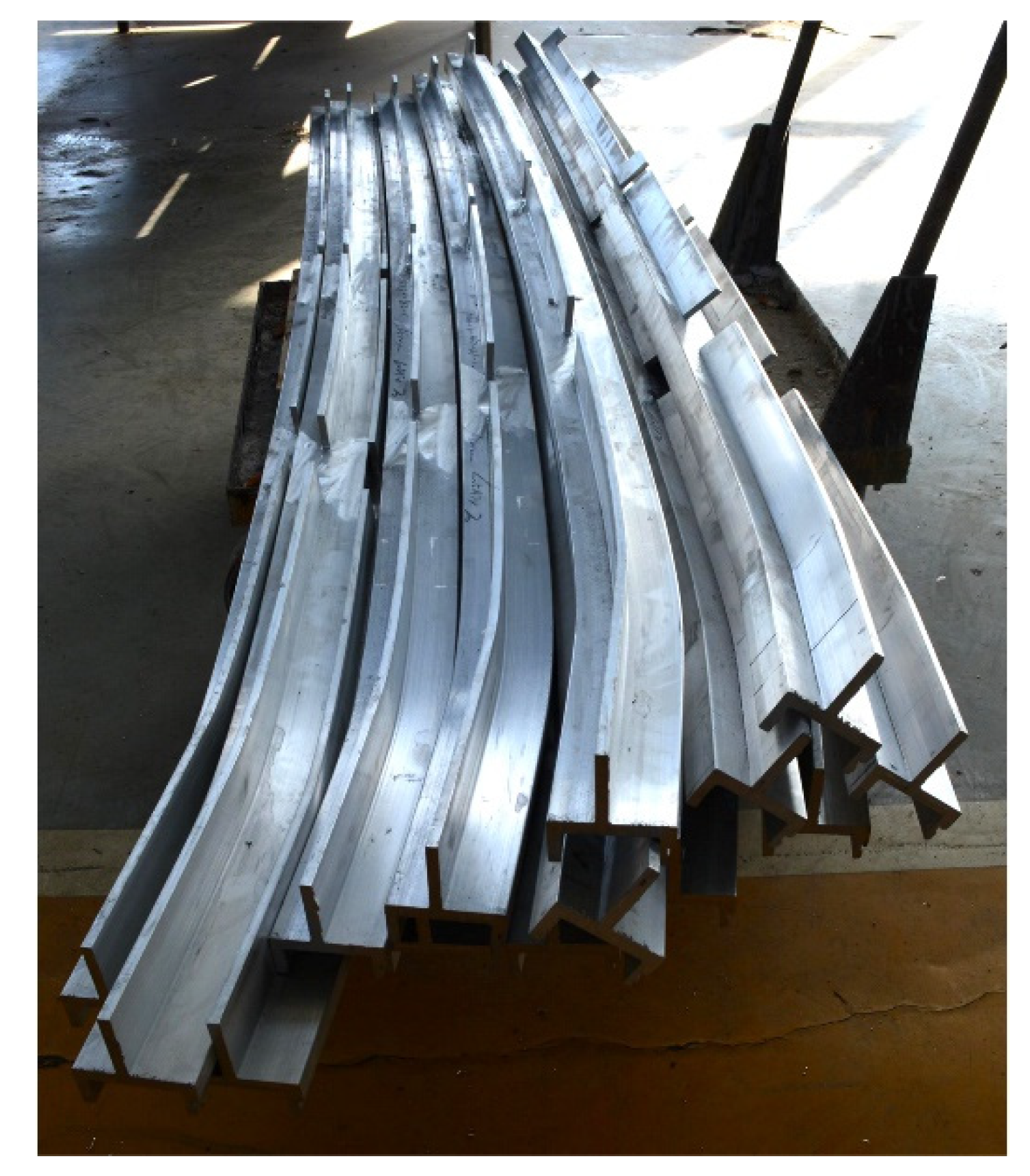
5.1. Experimental Steps
5.2. Experimental Steps
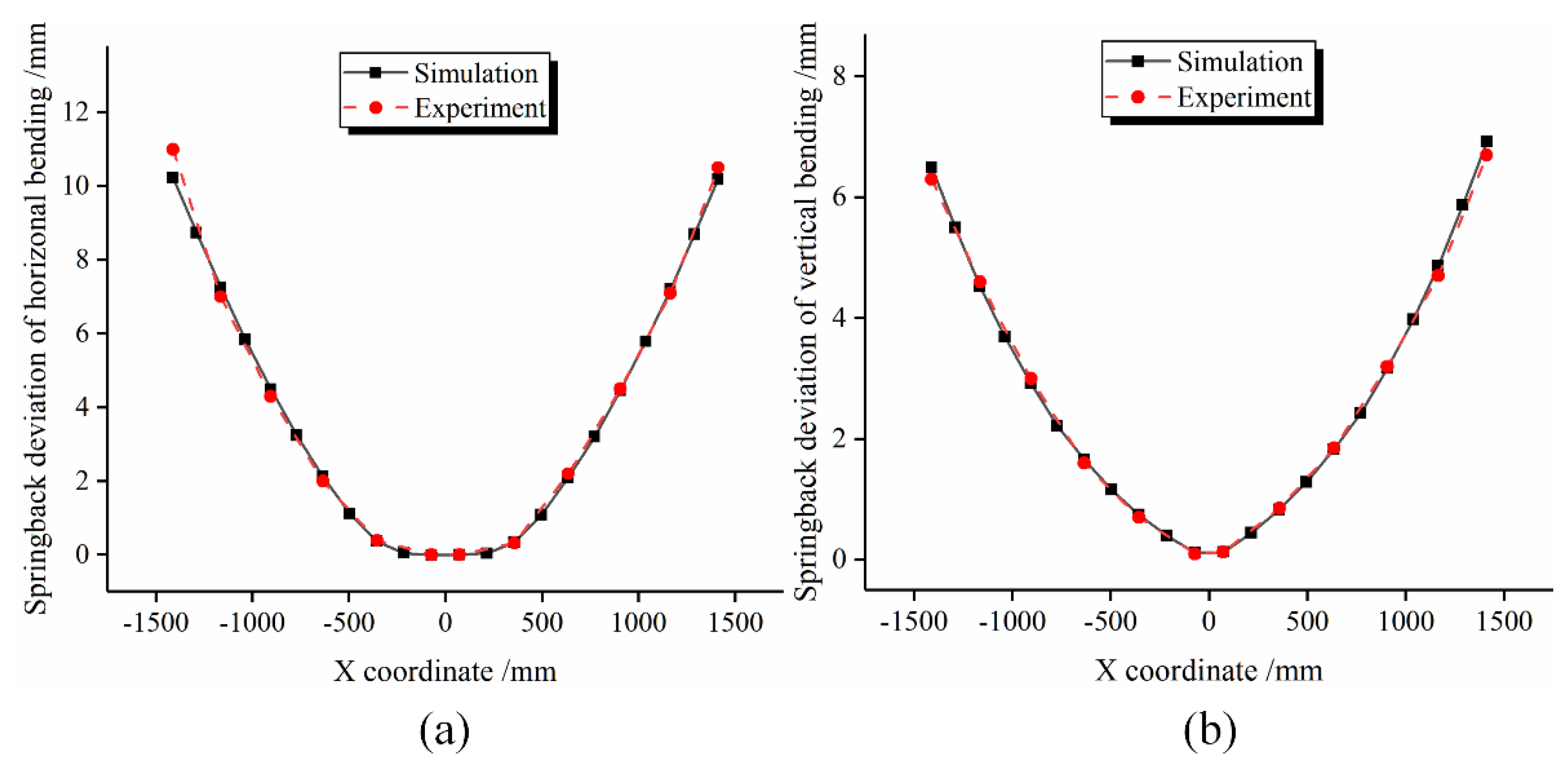
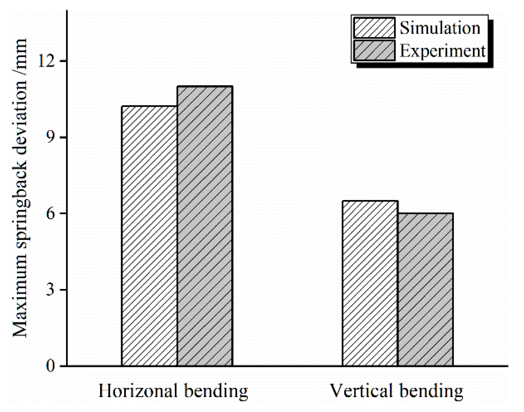
5.3. Comparison of Springback Deviation
6. Conclusions
- Horizontal bending radius and vertical bending radius have great influence on springback deviation of the Y-profile. With the increase in horizontal bending radius, the springback deviation of horizontal bending and vertical bending gradually decreases. With the increase in vertical bending radius, the springback deviation of horizontal bending gradually increases, and the springback deviation of vertical bending gradually decreases.
- The shorter the transition zone length, the smaller the springback deviation of horizontal bending and vertical bending. This is mainly because the longer the transition zone, the greater the tensile force required, and the distribution of stress and strain is more uneven.
- The smaller the radius of roller dies, the smaller the springback deviation of horizontal bending and vertical bending of the Y-profile. Die radius is also one of the important factors that affect the springback deviation of the workpiece in the FSB-MPRD process.
- In the horizontal bending process, the wall thickness of the profile has less influence on the springback deviation. However, in the vertical bending process, as the wall thickness increases, the springback deviation gradually decreases.
Author Contributions
Funding
Institutional Review Board Statement
Data Availability Statement
Acknowledgments
Conflicts of Interest
References
- Leu, D.-K.; Zhuang, Z.-W. Springback prediction of the vee bending process for high-strength steel sheets. J. Mech. Sci. Technol. 2016, 30, 1077–1084. [Google Scholar] [CrossRef]
- Zhang, S.; Wu, J. Springback prediction of three-dimensional variable curvature tube bending. Adv. Mech. Eng. 2016, 8, 168781401663732. [Google Scholar] [CrossRef] [Green Version]
- Nikhare, C.P. Springback Reduction by Using Tool Rollers. Int. J. Precis. Eng. Manuf. 2019, 21, 67–74. [Google Scholar] [CrossRef]
- Zhang, Z.; Wu, J.; Guo, R.; Wang, M.; Li, F.; Guo, S.; Wang, Y.; Liu, W. A semi-analytical method for the springback prediction of thick-walled 3D tubes. Mater. Des. 2016, 99, 57–67. [Google Scholar] [CrossRef]
- Wu, J.; Zhang, Z.; Shang, Q.; Li, F.; Wang, Y.; Hui, Y.; Fan, H. A method for investigating the springback behavior of 3D tubes. Int. J. Mech. Sci. 2017, 131–132, 191–204. [Google Scholar] [CrossRef]
- Zhang, D.; Li, Y.; Liu, J.; Xie, G.; Su, E. A novel 3D optical method for measuring and evaluating springback in sheet metal forming process. Measurement 2016, 92, 303–317. [Google Scholar] [CrossRef]
- Ouakdi, E.; Louahdi, R.; Khirani, D.; Tabourot, L. Evaluation of springback under the effect of holding force and die radius in a stretch bending test. Mater. Des. 2012, 35, 106–112. [Google Scholar] [CrossRef]
- Wasif, M.; Iqbal, S.A.; Tufail, M.; Karim, H. Experimental Analysis and Prediction of Springback in V-bending Process of High-Tensile Strength Steels. Trans. Indian Inst. Met. 2019, 73, 285–300. [Google Scholar] [CrossRef]
- Zhan, M.; Wang, Y.; Yang, H.; Long, H. An analytic model for tube bending springback considering different parameter variations of Ti-alloy tubes. J. Mater. Process. Technol. 2016, 236, 123–137. [Google Scholar] [CrossRef]
- Vasudevan, D.; Srinivasan, R.; Padmanabhan, P. Effect of process parameters on springback behaviour during air bending of electrogalvanised steel sheet. J. Zhejiang Univ. A 2011, 12, 183–189. [Google Scholar] [CrossRef]
- Chen, M.E.D. Numerical Solution of Thin-walled Tube Bending Springback with Exponential Hardening Law. Steel Res. Int. 2010, 81, 286–291. [Google Scholar] [CrossRef]
- Liu, Y.E.D. Springback and time-dependent springback of 1Cr18Ni9Ti stainless steel tubes under bending. Mater. Des. 2010, 31, 1256–1261. [Google Scholar] [CrossRef]
- Farhadi, A.; Nayebi, A. Springback analysis of thick-walled tubes under combined bending-torsion loading with consideration of nonlinear kinematic hardening. Prod. Eng. 2020, 14, 135–145. [Google Scholar] [CrossRef]
- Ozturk, F.; Toros, S.; Kilic, S.; Bas, M.H. Effects of cold and warm temperatures on springback of aluminium—Magnesium alloy 5083-H111. Proc. Inst. Mech. Eng. Part. B J. Eng. Manuf. 2009, 223, 427–431. [Google Scholar] [CrossRef]
- Rahmani, B.; Alinejad, G.; Bakhshi-Jooybari, M.; Gorji, A. An investigation on springback/negative springback phenomena using finite element method and experimental approach. Proc. Inst. Mech. Eng. Part. B J. Eng. Manuf. 2009, 223, 841–850. [Google Scholar] [CrossRef]
- Li, L.; Seo, Y.-H.; Heo, S.-C.; Kang, B.-S.; Kim, J. Numerical simulations on reducing the unloading springback with multi-step multi-point forming technology. Int. J. Adv. Manuf. Technol. 2009, 48, 45–61. [Google Scholar] [CrossRef]
- Abebe, M.; Yoon, J.-S.; Kang, B.-S. Radial Basis Functional Model of Multi-Point Dieless Forming Process for Springback Reduction and Compensation. Metals 2017, 7, 528. [Google Scholar] [CrossRef] [Green Version]
- Wang, A.; Zhong, K.; El Fakir, O.; Liu, J.; Sun, C.; Wang, L.-L.; Lin, J.; Dean, T.A. Springback analysis of AA5754 after hot stamping: Experiments and FE modelling. Int. J. Adv. Manuf. Technol. 2016, 89, 1339–1352. [Google Scholar] [CrossRef] [Green Version]
- Liu, Z.; Li, L.; Wang, G.; Chen, J.; Yi, J. Springback behaviors of extruded 6063 aluminum profile in subsequent multi-stage manufacturing processes. Int. J. Adv. Manuf. Technol. 2020, 109, 1–13. [Google Scholar] [CrossRef]
- Liang, J.; Chen, C.; Li, Y.; Liang, C. Effect of roller dies on springback law of profile for flexible 3D multi-point stretch bending. Int. J. Adv. Manuf. Technol. 2020, 108, 3765–3777. [Google Scholar] [CrossRef]


| E/GPa | V | σs/MPa | ρ/g·cm–3 | K/MPa | N |
|---|---|---|---|---|---|
| 70 | 0.33 | 254 | 2.71 | 418.7 | 0.105 |
| Process Parameters | Value |
|---|---|
| Section shape | Y-profile |
| Length of profile (mm) | 3000 |
| Pre-stretching length δpr (mm) | 30 |
| Post-stretching length δpo (mm) | 30.3 |
| Mass scaling factor | 300 |
| Friction coefficient | 0.15 |
| Rh (mm) | 2000, 2500, 3000, 3500 |
| Rv (mm) | 6000, 7000, 8000, 9000 |
| Transition zone length (mm) | 200, 300, 400, 500 |
| Radius of roller dies R (mm) | 50, 55, 60 |
| Wall thickness of profile (mm) | 8, 9, 10, 11 |
| Process Parameters | Value |
|---|---|
| Section shape | Y-profile |
| Length of profile (mm) | 3000 |
| Pre-stretching length δpr (mm) | 30 |
| Post-stretching length δpo (mm) | 30.3 |
| Rh (mm) | 2500 |
| Rv (mm) | 7000 |
| Transition zone length (mm) | 400 |
| Radius of roller dies R (mm) | 50 |
Publisher’s Note: MDPI stays neutral with regard to jurisdictional claims in published maps and institutional affiliations. |
© 2021 by the authors. Licensee MDPI, Basel, Switzerland. This article is an open access article distributed under the terms and conditions of the Creative Commons Attribution (CC BY) license (https://creativecommons.org/licenses/by/4.0/).
Share and Cite
Chen, C.; Liang, J.; Li, Y.; Liang, C.; Jin, W. Springback Analysis of Flexible Stretch Bending of Multi-Point Roller Dies Process for Y-Profile under Different Process Parameters. Metals 2021, 11, 646. https://doi.org/10.3390/met11040646
Chen C, Liang J, Li Y, Liang C, Jin W. Springback Analysis of Flexible Stretch Bending of Multi-Point Roller Dies Process for Y-Profile under Different Process Parameters. Metals. 2021; 11(4):646. https://doi.org/10.3390/met11040646
Chicago/Turabian StyleChen, Chuandong, Jicai Liang, Yi Li, Ce Liang, and Wenming Jin. 2021. "Springback Analysis of Flexible Stretch Bending of Multi-Point Roller Dies Process for Y-Profile under Different Process Parameters" Metals 11, no. 4: 646. https://doi.org/10.3390/met11040646
APA StyleChen, C., Liang, J., Li, Y., Liang, C., & Jin, W. (2021). Springback Analysis of Flexible Stretch Bending of Multi-Point Roller Dies Process for Y-Profile under Different Process Parameters. Metals, 11(4), 646. https://doi.org/10.3390/met11040646