Article

Influence of Grain Orientation Distribution on the High Temperature Fatigue Behaviour of Notched Specimen Made of Polycrystalline Nickel-Base Superalloy

1
Gasturbine and Transmission Research Center (G2TRC), University of Nottingham, Nottingham NG7 2RD, UK
2
Institute of Applied Materials—Applied Materials Physics, Karlsruhe Institute of Technology, 76344 Eggenstein-Leopoldshafen, Germany
3
Gas and Power Division, Department for Technology & Innovation, Siemens AG, 10553 Berlin, Germany
4
Institute of Materials Science and Engineering, University of Kaiserslautern, 67655 Kaiserslautern, Germany
*
Author to whom correspondence should be addressed.
Metals 2021, 11(5), 731; https://doi.org/10.3390/met11050731
Submission received: 12 April 2021 / Revised: 26 April 2021 / Accepted: 26 April 2021 / Published: 29 April 2021
(This article belongs to the Special Issue High-Temperature Behavior of Metals)

Abstract

:
Two different material batches made of random and textured orientated polycrystalline nickel-base superalloy René80 were investigated under isothermal low cycle fatigue tests at 850 °C for a notched specimen geometry. In contrast to a smooth specimen geometry, no significant improvement in fatigue behaviour of the notched specimen could be observed for the textured material. Finite element simulations reveal an area along the notch where high stiffness evolves for the textured material, which lead to nearly similar shear stresses in the slip systems compared to a random orientation distribution and therefore to no distinct differences in the lifetime.

1. Introduction

The worldwide demand for the reduction of CO2 emissions during power generation and the associated increased usage of renewable energy sources has lead to fluctuation in the power supply and can cause problems with regard to power grid stability. In particular, the generation of wind and solar power is strongly dependent on the current weather conditions, which result in volatile energy input into the power grid. In order to fill in these gaps, gas power plants are used due to their ability to generate power in short times. Modern gas turbines, as a main part of gas power plants, can be started from cold to maximum power output in less than 30 min [1]. Due to frequent starts, stops and load changes from part to full load, the materials in the hot gas section and especially the turbine blades have to withstand significantly fluctuating mechanical and thermal loads. Hence, thermo–mechanical fatigue, high-temperature fatigue behavior and creep effects of the turbine material must be investigated in order to reach high efficiencies with simultaneous economic design aspects. Since component testing is very complex and expensive, generally, a standardized specimen of the used material is examined under high-temperature fatigue conditions. To represent uniaxial stress states, specimens with cylindrical gauge sections are used; moreover, notched specimens are used to determine the fatigue behavior of the material under multiaxial stress states as well as stress gradients to represent complex component structures. Besides experimental material testing, numerical models are indispensable during the design process in order to predict the deformation and fatigue behavior under various load and temperature conditions. Based on experimental observed and measured mechanical material responses, models such as the commonly used Ramberg–Osgood or the Chaboche model are used to describe the nonlinear stress strain relationship for materials under high-temperature conditions [2,3,4].
Polycrystalline nickel-base superalloys, such as René80, are used as blades or vanes in the rear hot gas sections of gas turbines with maximum operating temperatures up to 982 °C [5,6]. Due to the conventional vacuum casting process of the turbine blades, different grains sizes and orientation distributions arise depending on the component geometry and cooling conditions. Coarse grains and low grain numbers located in highly stressed component areas in combination with high elastic anisotropies of nickel-base superalloys lead to large scattering in fatigue lifetimes and mechanical properties [7,8,9], which lead to high safety factors for deterministic design approaches. In order to achieve higher efficiencies for the components, these conservative deterministic lifetime models are successfully replaced by probabilistic approaches [10,11,12,13]. For this purpose, the influencing factors and their statistical distributions on high-temperature fatigue behavior must be identified and investigated for the material. Seibel et al. [11,14] investigated the fatigue behavior of conventionally casted polycrystalline nickel-base superalloy René80 with an assumed random grain orientation distribution under low cycle fatigue (LCF) conditions at 850 °C. For the same total strains, notched specimen shows a distinct increased fatigue lifetime compared to the smooth specimen. This can be mainly attributed to the statistical size effect, where the notched specimen has a significantly reduced highly loaded volume and therefore the probability of grains which tend to crack initiation is decreased. In addition, the formation of stress gradients, caused by the notch geometry, lead to decreased stresses into the bulk material, which could result in lower crack growth rates and therefore to longer lifetimes compared to cylindrical specimens. For different notch geometries, an increase in lifetime with an increase of the notch factor could be shown. A similar behavior could also be proven for different material such as steels [15].
Numerical evaluations in [16], considering the influence of grain orientation on the mechanical behavior of nickel-base superalloys, reveal a relationship between the local grain orientation and the resulting shear stress within the slip system, responsible for plastic deformation. Due to high elastic anisotropies of nickel-base superalloys, the highest shear stresses for the <111>{110} slip systems were achieved for grain orientations with corresponding Young’s moduli between 180 GPa and 230 GPa (at 850 °C), and Schmid factors between 0.38 and 0.46 for uniaxial loading cases. Orientations with a maximum in Schmid factors of 0.5 show distinct lower shear stresses, due to low correlated elastic properties at around 120 GPa.
Engel, Mäde et al. showed in [17] the influence of the local grain orientation on the probability of fatigue failure for smooth cylindrical specimen made of polycrystalline René80 with a random and textured grain orientation distribution. By determining that the grain orientation depended on the resulting shear stress within the slip systems of the material by polycrystalline finite element simulation, reliable probabilistic lifetime predictions could be made for randomly orientated material as well as textured material. As a fatigue life describing parameter, a modified Schmid factor approach was introduced. For the nodes of a polycrystalline finite element simulation, the modified Schmid factor is defined as the quotient of von Mises stress and the resulting shear stress in the activated slip systems. It could be shown that the determined texture of the investigated material lead to a lower Young’s moduli for the cylindrical specimen and therefore to lower stresses during uniaxial strain controlled tests compared to the randomly orientated material. Furthermore, the texture influences the orientation of the slip system and lead to lower modified Schmid factors. Thus follows the requirement of higher local stresses in the slip system which results in a delay in crack initiation whereby higher fatigue lifetimes were achieved.
In addition to the results of different smooth-specimen grain orientation distributions in [17,18], the following paper investigates the high-temperature LCF behavior of the same material batch of nickel-base superalloy René80 for a notched specimen geometry. Isothermal LCF tests at 850 °C were carried out for a random and a textured grain orientation distribution, and the lifetimes compared to the smooth specimen from previous investigations. To explain the observations and differences in the lifetimes as well as the variation in mechanical behavior, polycrystalline finite element simulations for notched geometries were carried out to analyze the influence of local grain orientation on the local mechanical behavior during cyclic high-temperature fatigue tests.

2. Materials and Methods

The composition of the polycrystalline nickel-base superalloy René80 used in this work is shown in the following Table 1 and was measured by the manufacturer.
The material was vacuum casted from the same melt and heat treated after [19] at Doncaster in Bochum/Germany as bars of 150 mm in length with 20 mm and 12 mm in diameter. The different diameters of the bars lead to different cooling conditions and temperature transients during solidification in the radial direction (x−direction, see Figure 1). In addition, the casting process as a standing mould leads to a further temperature gradient in the axial direction (y–direction). Due to the faster cooling conditions in the 12 mm bar, grain growth is inhibited, which leads to smaller elongated grains compared to the 20 mm bar, as Figure 1 shows. The white dashed line represents the gauge section of the smooth specimen, and the green dashed line the gauge section of the notched specimen.
The preferred growth of the [100]–orientation towards the temperature gradients known for nickel-based superalloys leads to dendritic solidification along the edge areas of the bars [20] represented as blue dotted lines. During manufacturing of the sample geometries, the dendritic edge area is almost completely removed from the gauge section of the 20 mm rod. However, the samples, which were manufactured from the 12 mm rod, still show dendritic structures within the gauge section, as seen in Figure 1. As described in [17], the dendritic solidification and the resulting preferential direction of the grains, with an average alignment of ϑ = 25°, result in a different material behavior compared to the specimen from the 20 mm bar material (with random orientation). To determine the grain size, the grains in the gauge section were evaluated by the equivalent diameter using a light microscope and an image processing software. The ratio of the grain sizes within the gauge section of the specimen between the 12 mm bar and 20 mm bar is about 1:3. In the following, the specimen taken from the middle of the 20 mm bar will be called coarse-grained and consist of a random orientation distribution of the grains, since no obvious crystallographic texture could be determined using electron backscatter diffraction. The specimens made from the 12 mm bar are called fine-grain textured material, due to the preferred solidification in direction of the resulting temperature gradient. The René80 material from the isothermal LCF tests results taken from [14] for comparison was also manufactured and heat-treated by Doncaster but casted as solid plate with a thickness of 20 mm. The grain sizes are in a very good accordance to the coarse-grain material as well as the grain orientation distribution was also described as random. In order to compare the results to [14], the same notch geometry as well as cylindrical gauge section were chosen and are shown in Figure 2. The notch factor was calculated to a value of 1.62.
Isothermal LCF tests were carried out at 850 °C at a servo hydraulic MTS test rig with a maximum load capacity of 100 kN combined with an Hüttinger TrueHeat (TRUMPF Hüttinger GmbH, Germany, Freiburg) MF 5000 induction heating system. Strain-controlled tests were performed at R = −1, using an MTS high-temperature extensometer type 632.53 with ceramic rods, a measurement length of 12 mm and a constant air flow cooling to prevent temperature influences on the measurement. All tests were carried out with a test frequency of 1 Hz. Details to the tests conducted with the smooth samples can be found in [17,21].
Since the used type K ribbon thermocouple could not be applied in the notch due to geometrical conditions, it was attached above and calibrated for each specimen to the temperature of 850 °C by means of a wire thermocouple within the notch. The thermal gradient between these two thermocouples was below 8 °C for 850 °C, whereas a controlling by only one wire thermocouple attached at the notch was not practicable due to contact problems during testing. A drop of the measured and stabilized stress amplitude of 2.35% indicates the failure of the notched specimen, which is equal to a drop of 2.5% for the smooth specimen if a penny-shaped crack surface of 0.96 mm² in both specimen types is assumed [22].
It should be noted here that due to confidential agreements with the project partners, diagrams which contain lifetime and material data of the investigated material René80 are normalized. Wöhler diagrams are labelled with “low” and “high”, which refers to lifetimes and total strain, and stress amplitudes for the low cycle fatigue and high cycle fatigue regime. Diagrams which contains material properties are normalized by the highest occurring value.

3. Modelling Approaches

3.1. Modelling the Notch Strain with Finite Element Analysis for an Isotropic Material Assumption

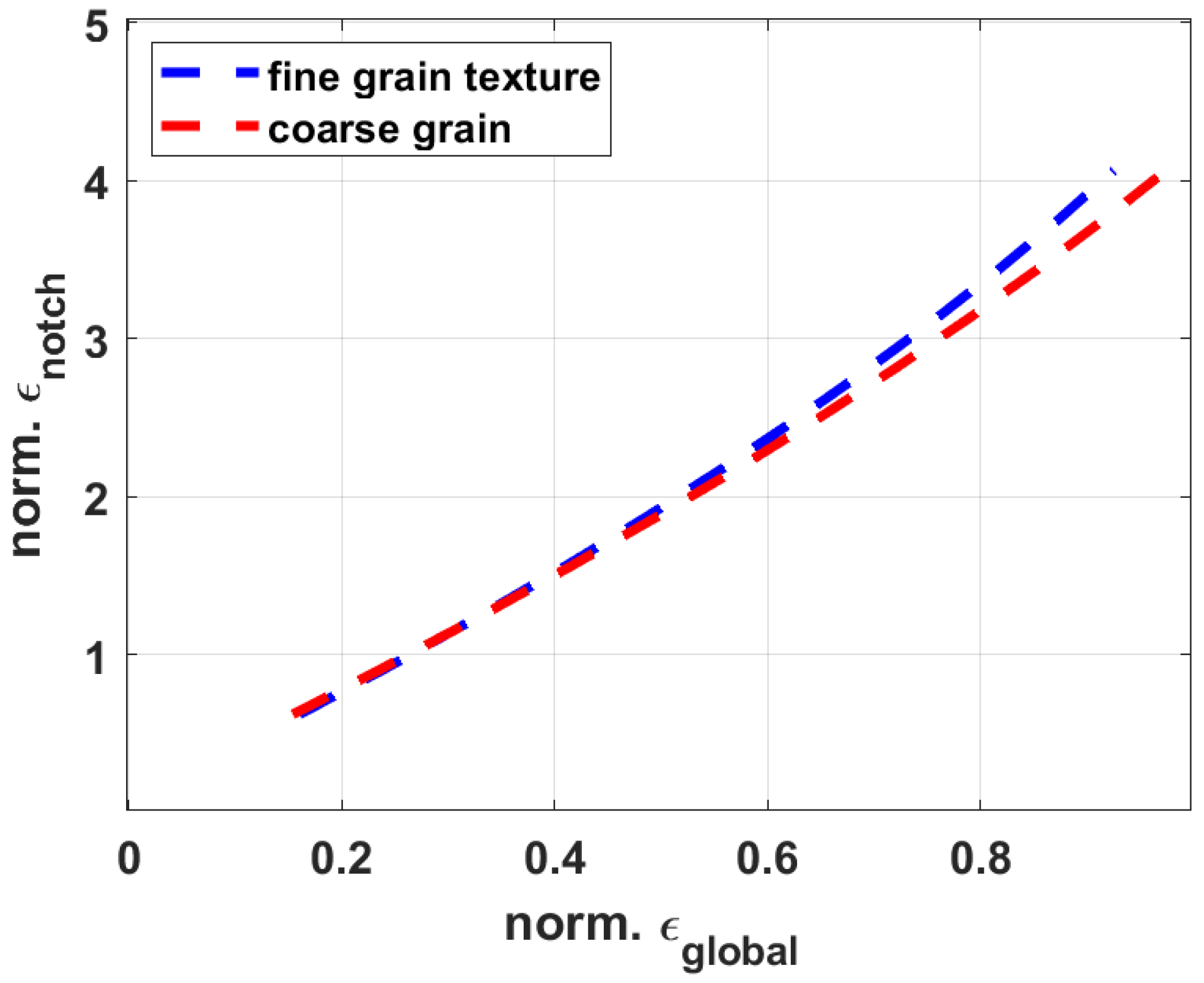
Due to the usage of the MTS 12-mm high-temperature extensometer for both specimen types, the axial strain within the notch must be determined numerically, in order to compare the fatigue tests to smooth specimen fatigue tests in strain amplitude Wöhler diagrams. Due to the notch geometry, stress concentrations occur within the notch root and lead to local plastic deformation. Therefore, an isotropic elastic plastic material model, based on a Ramberg–Osgood relationship (material parameters provided by Siemens), for the coarse-grained and fine-grain textured René80 at 850 °C, was implemented into the finite element solver ABAQUS (Version 2018, Dessault systemes, Vélizy-Villacoublay, France). A virtual extensometer with a measurement length of 12 mm was attached symmetrically around the notch of a full specimen model. As a global loading, the end face of the model was displaced step by step, where the front face was locked in the axial direction. For each step, the measured axial strain on the extensometer was determined as well as the axial strain within the notch root. The following Figure 3 shows the relationship between the axial strain applied to the extensometer εglobal (respectively to the specimen) and the corresponding strain in the notch root εnotch for the coarse- and fine-grain textured material (normalized with the maximum occurring global strain εglobal).
To estimate the required strain amplitude within the notch root, fitted quadratic functions (from Figure 3) were used to adjust the total strain control value at the fatigue test controlling system.

3.2. Modelling the Local Material Behaviour with Finite Element Analysis for Polycrystalline Nickel-Base Superalloys

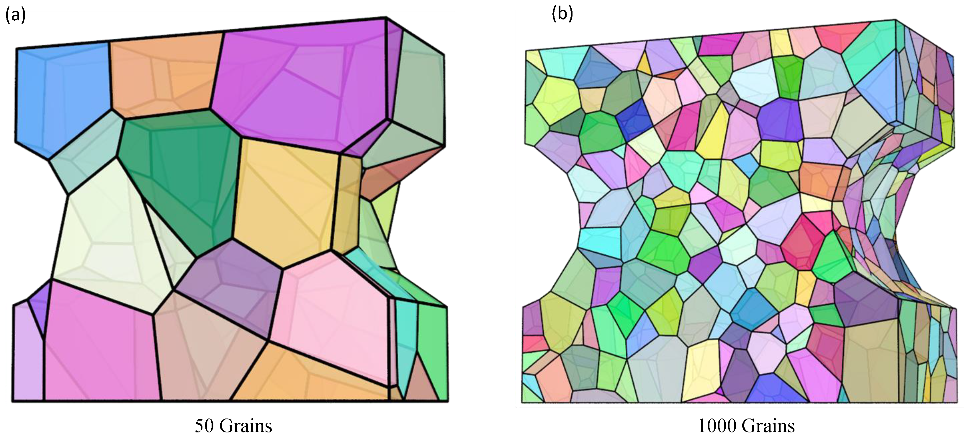
In order to simulate the material behaviour in dependence of different grain orientation distributions, the open-source software NEPER (Version 3.3, by Romain Quey, MINES Saint-Étienne, France) was used to generate random grain morphologies using the 3D Voronoi tessellation method [23,24,25]. Since the notched section is of great importance for the mechanical behaviour of the specimen, a cuboid with the dimension 10 mm × 11 mm × 5.5 mm and two notches, according to Figure 4, was modelled. The thickness of the model was chosen to ensure that the surface of the two notches is equal to the circumferential surface of the round notch on the test specimen in order to avoid statistical size effects. The cuboid type of model was selected because it is not practicable to perform rotationally symmetrical cuts on cylindrical models within the used version of NEPER. Due to the considerations of a flat notched specimen in the finite element models, differences in the stress state of the notch root occur when compared to a circumferential notched specimen, as used in the experiment. For example, the tangential stress component of the circumferential notched specimen is not existent in the flat notched specimen. However, because of the low notch factor of 1.62, the axial stress component is significantly higher than the remaining stress components and therefore these differences in stress state can be neglected.
According to the grain size distribution mentioned in Section 2, the coarse-grain model with random orientation distribution contains of 100 grains, which result in an equivalent grain diameter of 2.76 ± 0.55 mm, evaluated using the NEPER grain statistics tool. The fine-grain textured model contains of 1000 grains with an equivalent grain diameter of 1.03 ± 0.16 mm. Due to the very high computing time for generation, meshing and calculation, three models with three textured grain orientation distributions each were created for the fine-grain textured sample. The coarse-grained models cover four different models with three different grain orientation distributions each. For both types of models, the value for the characteristic length of the elements for the average cell size was set to rcl = 0.3 (relative element length) within the NEPER meshing tool. As a result, the mesh consists of a uniform distribution of approximately 250,000 quadratic tetrahedral elements (C3D4) for the coarse-grain model and approximately 700,000 quadratic tetrahedral elements (C3D4) for the fine-grain textured model. Both polycrystalline specimen models are shown in Figure 4. Note, the edges within the notch appear in the visualization and are removed by the meshing procedure.
A detailed description of the model properties of the smooth specimen as well as generation is described in [17]. In order to expand the simulation database, six coarse-grain smooth models with random orientation distributions and six fine-grain smooth models with a textured orientation distribution were added and analysed. Table 2 summarises all conducted numerical simulations with the corresponding orientation distributions.
In order to create local material properties, each grain was rotated using rotational matrices U (U is a function of the Euler angles φ1, φ2 and ϑ) according to an orientation distribution in a pre-processing step and the respective data written to the input file. The grains in the coarse-grain René80 batch show no preferential direction in orientation, which is why the rotational matrices U used in this pre-processing step are distributed according to an isotropic measure, mathematically given by the Haar measure at the SO3 group of rotations [10]. The rotational matrices U which were assigned to the fine-grain textured models were generated by random distribution of the Euler angles φ1, φ2 where ϑ kept constant with 25° to represent the examined texture. To calculate the elastic properties of the grains in dependence of their local coordinate system, a global, anisotropic, linear-elastic material law was defined in ABAQUS. As there is no data concerning the elastic constants of René80 in dependence of the temperature in the literature, elastic values for an IN738LC were taken from [26]. Since both the composition and content of the γ’ phase are very similar in IN738LC and René80, it can be assumed that the elastic behaviour of both alloys are qualitatively comparable. A linear interpolation from the data at 800 °C and 898 °C results in the elastic constants C11 = 225.83 MPa, C12 = 161.45 MPa and C44 = 98.79 MPa for a temperature of 850 °C. During the simulation, the local material properties in dependence of the local grain orientation were transferred to the globally defined material law and the grains interact according to their local stiffness. All simulations were carried out at T = 850 °C in displacement control, in order to achieve consistency to the LCF experiments. The nodes of one face were locked only in the axial direction, in order to enable transverse contraction, whereas the nodes of the opposite face were displaced by 0.01 mm. Due to the cyclic stability of the material behaviour during high-temperature LCF testing, only one single loading cycle was simulated.
A python-based tool was developed to calculate the maximum resulting shear stress within the slip systems (i,j) on each node of the finite element models in dependence of the local stress tensor σ and the assigned local grain orientation U. Since the crystallographic structure of nickel-base superalloys is face-centred cubic (fcc), dislocation movement occurs usually in slip systems of the type {111}<110> if a critical value τcrit is exceeded. The resulting shear stress on each node is determined by calculating the shear stresses for all 12 slip systems, where the slip system with the highest value is the activated one—see Equation (1).
τres,ij = U∙ni σ∙U∙si,j
Details for the calculation procedure can be found in [10,17,21]. Since all simulations are purely elastic, only linear elastic shear stresses are calculated within the slip systems. Still, their distribution at the model surface, i.e., the notch root, gives an indication about the expected onset of plasticity and therefore the possibility of a fatigue crack initiation.

4. Results

4.1. Experimental Results of Isothermal LCF Tests at 850 °C for Smooth and Notched Specimen

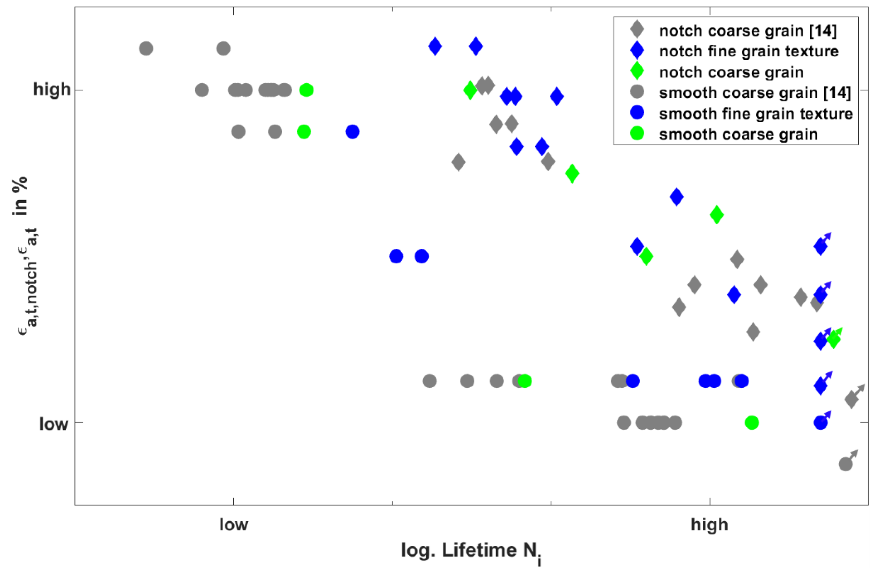
In the following section, the results of the total strain-controlled isothermal LCF experiments at 850 °C of the notched specimen are presented in comparison to the results of the smooth specimen. Figure 5 shows the influence of grain orientation distribution and specimen geometry on the high-temperature LCF behaviour of René80 as the total strain amplitude Wöhler curve. For the notched specimen, the shown total strain amplitude εa,t,notch represents the total strain amplitude within the notch root (see Section 3.1), determined by finite element simulation using a Ramberg–Osgood relationship. The investigated coarse-grained specimens are displayed in green, whereas, in addition, the results for coarse-grain smooth and notched specimens (taken from [14]) are shown in grey. Smooth and notched specimens made from the fine-grain textured material are marked in blue. Smooth specimens are shown as circular data points, whereas notched specimens are represented by a rhombus. Run out tests are marked with an arrow.
Figure 5 clearly shows, for all total strain amplitudes and grain orientation distributions, that fatigue lifetimes of the notched specimen are higher compared to the smooth specimen. As already explained in [17,21], smooth specimens with a fine-grain textured material show higher lifetimes compared to the coarse-grain material, especially for low total strains. However, for the notched specimens, no unambiguous improvement regarding fatigue life can be found for the fine-grain textured material. It is noticeable that over a relatively large range of low total strains, both failure and run out occur for the notched geometry, which leads to distinct lifetime scattering. At high total strains, the lifetime scatter appears slightly decreased.
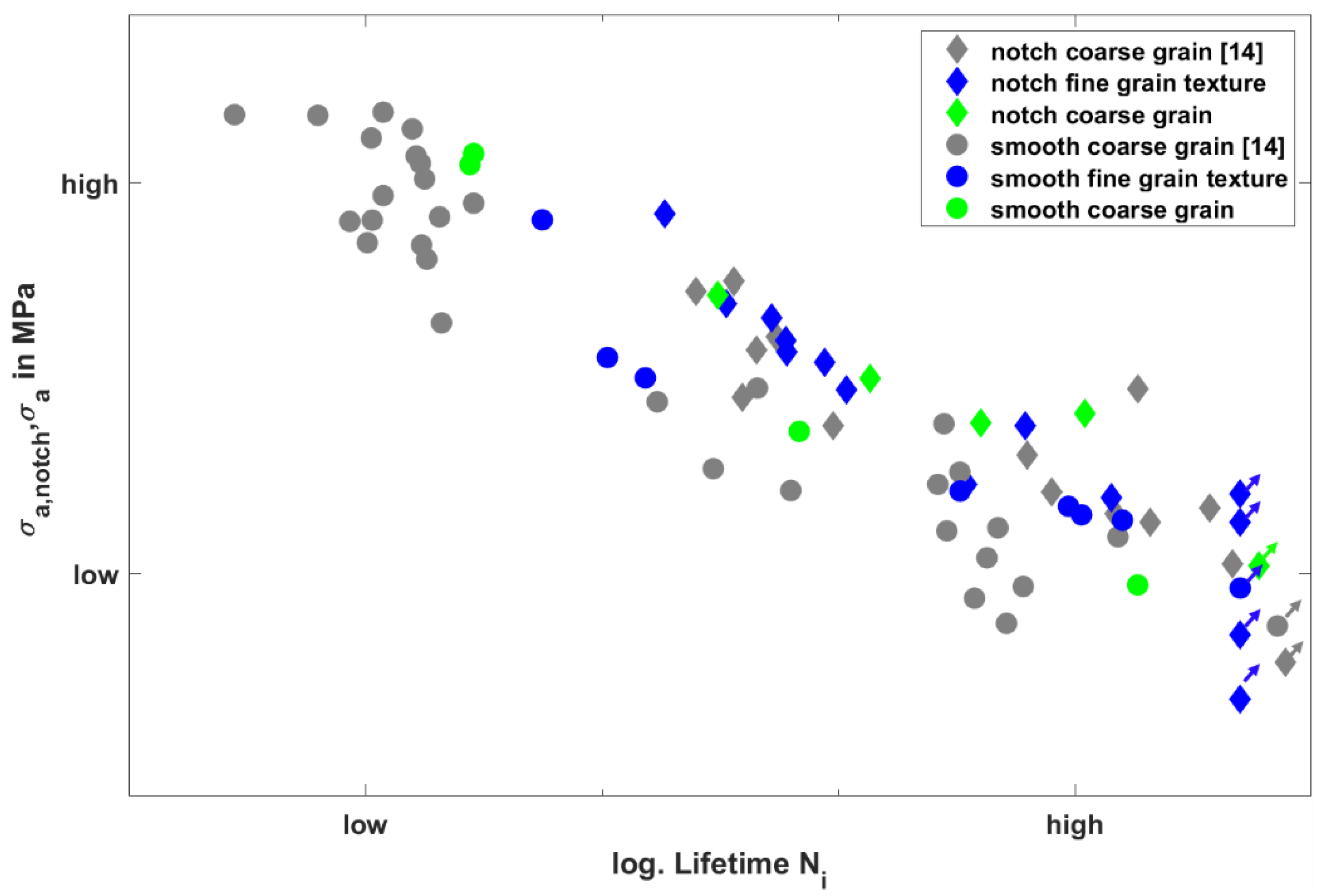
Figure 6 shows the measured stress amplitude in order to represent the influence of stiffness of the individual specimens. For the notched specimen, the stress amplitude corresponds to the maximum stress in the notch root (σa,notch).
For the notched specimen, the measured stress amplitudes are in general lower compared to the smooth specimen for the same total strains. While the smooth specimen shows a clearly lower stress amplitude for the textured fine-grain material, no clear influence of grain orientation on the stress amplitude for the notched specimen can be determined. Additionally, the scatter in stress amplitude seems, for the smooth specimen, much higher compared to the notched specimen, where the highest scatter could be found for the coarse-grain smooth specimen.

4.2. Microscopic Analysis of the Fracture Aurfaces

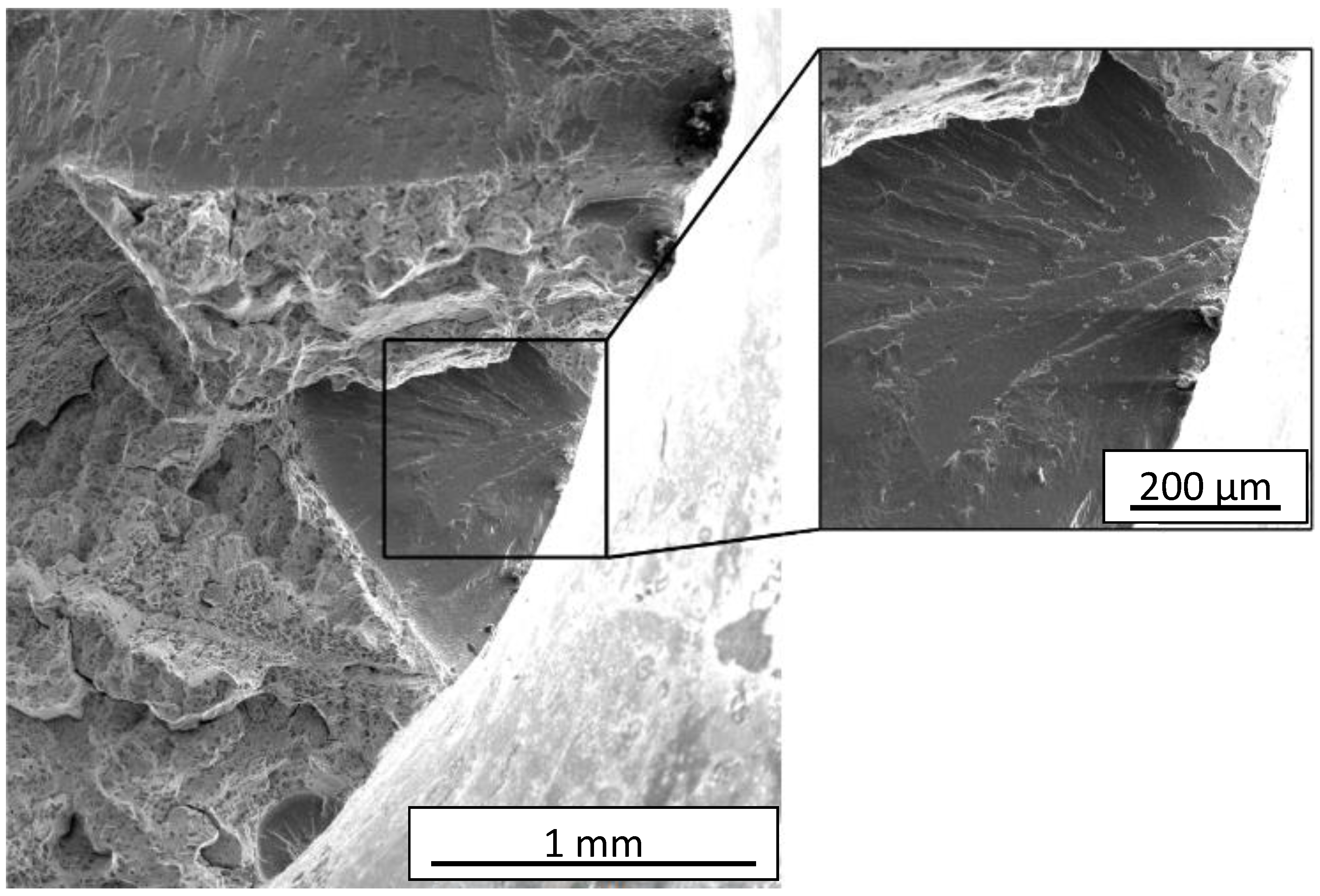
The fracture surfaces of the notched specimen will be evaluated in the following, where a detailed analysis of the fracture surface for the smooth specimen can be found in [18]. In general, the typical high-temperature fatigue cracking behaviour is observed, consisting of a smooth and oxidized part which represents the fatigue crack surface, which was developed during cycling and a rough non-oxidized part which represents the residual fracture surface (caused by the shutdown of the heating system after specimen failure). Moreover, scanning electron microscope (SEM) images show the typical honeycomb structure and prominent cracks in the residual fracture area. Conversely, the detailed examination of the fatigue crack surface clearly shows the crack initiation sites at the surface with the typical lens around the initiation spot. Subsequently, river patterns are visible in the fatigue rupture surface by SEM investigations, as visible in Figure 7.
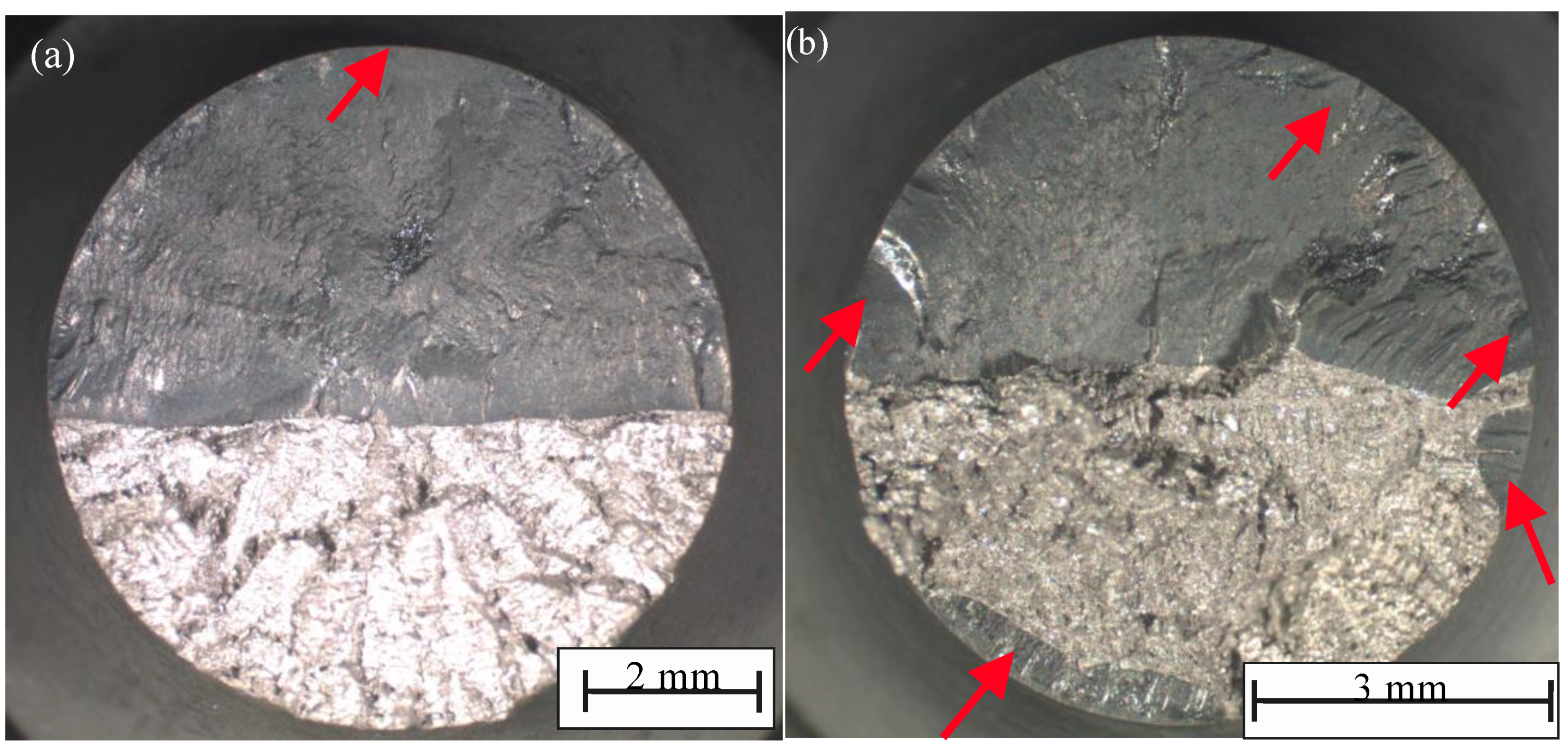
Independent of specimen geometry, the fractured surfaces show an influence of the total strain amplitude. At low total strain amplitudes, single crack initiation with large fatigue surfaces were observed, as seen in Figure 8a. Almost half of the fracture surface is represented by the fatigue crack originating from the single crack initiation site, while the other half is dominated by final rupture surface. In contrast, at high total strain amplitudes, multiple crack initiation sites distributed all around the notch root were observed, as shown in Figure 8b. High strains and therefore higher stresses lead to multiple crack initiation sites and faster crack growth. As a result, the fatigue surfaces are significantly smaller and irregularly shaped. Partially, the merging of cracks can be observed. The red arrows in Figure 8 illustrate the crack initiation site.

4.3. Cyclic Deformation Behaviour of the Notched Specimen under Total Strain Control

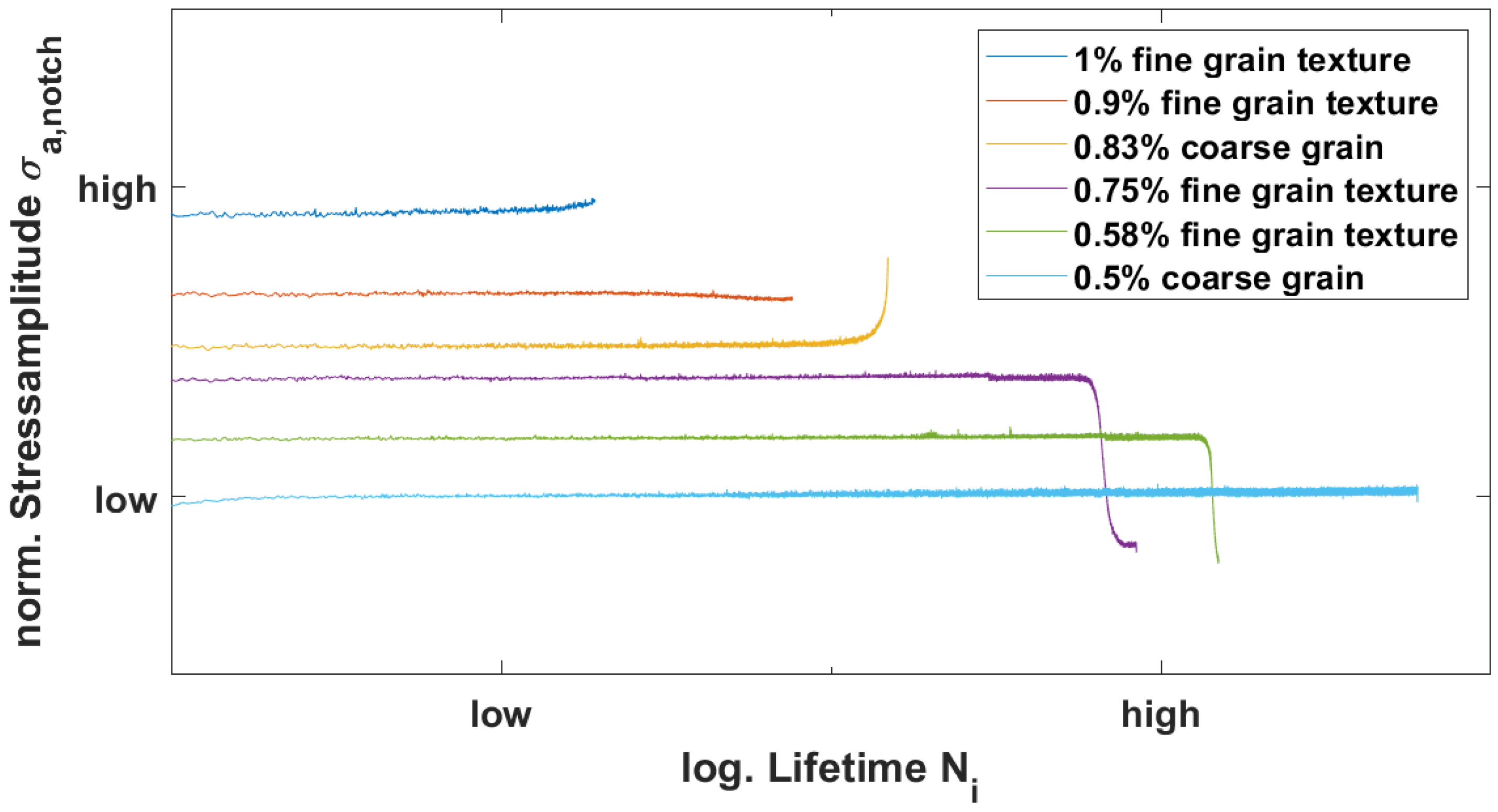
The development of stress amplitude σa,notch for the notched specimen over the cycle number is presented in Figure 9 (total strain amplitudes are normalized).
As expected, the stress amplitude σa,notch decreases with a decrease of total strain amplitude, which results in longer lifetimes. All curves show a stable cyclic behaviour during their full lifetime until a crack initiation occurs; therefore, their cyclic behaviour is comparable to the smooth specimen [18]. After crack initiation, some samples show a steep drop in stress amplitude σa,notch. However, stress amplitude increases are also possible. After [27], this effect can be explained by the position of the crack relative to the extensometer. Since the duration of the crack growth phase is distinctly smaller compared to the total lifetime, the effect of the orientation of the crack to the extensometer can be neglected.

4.4. Results of the Finite Element Simulation

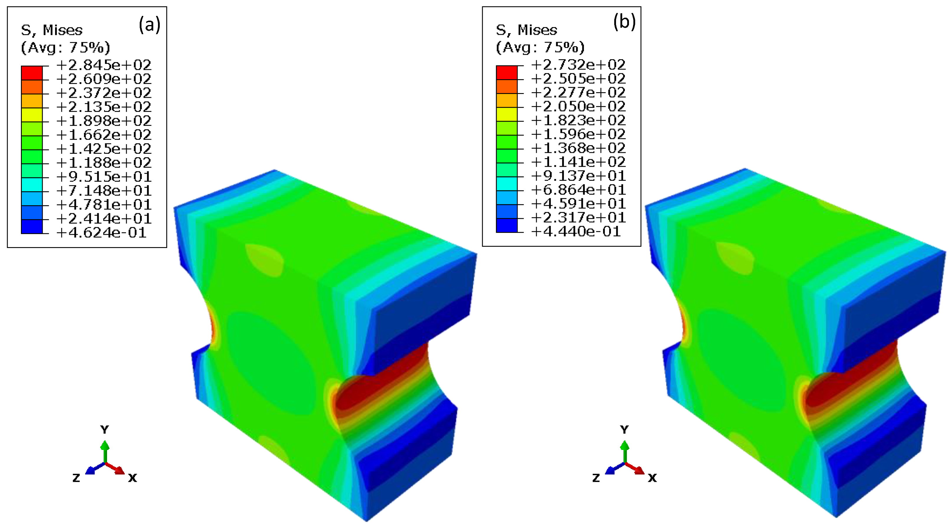
For the determination of the elastic axial strains within the notch, results of the isotropic simulations based on the Ramberg–Osgood relationship (mentioned in Section 3.1) are shown in Figure 10. The axial displacement of 0.1% in the y–direction in the following illustrations was chosen to compare the results with the anisotropic approaches and to avoid plastic deformation (the polycrystalline simulations are calculated fully elastic). In order to differentiate the two material batches, the respective Young’s moduli (taken from the Ramberg–Osgood relationship) were assigned to the models.
The von Mises stress distribution reveals the anticipated inhomogeneous distribution within the notch where the maximum von Mises stress is located within the notch root, with 284.5 MPa for the coarse-grain material and 273.2 MPa for the fine-grain textured material. Due to the slightly lower Young’s moduli of the fine-grain textured material, the local stresses are slightly decreased compared to the coarse-grained material. In addition, the isotropic simulation shows a geometrically caused slight reduction of the stress at the edges of the notch.
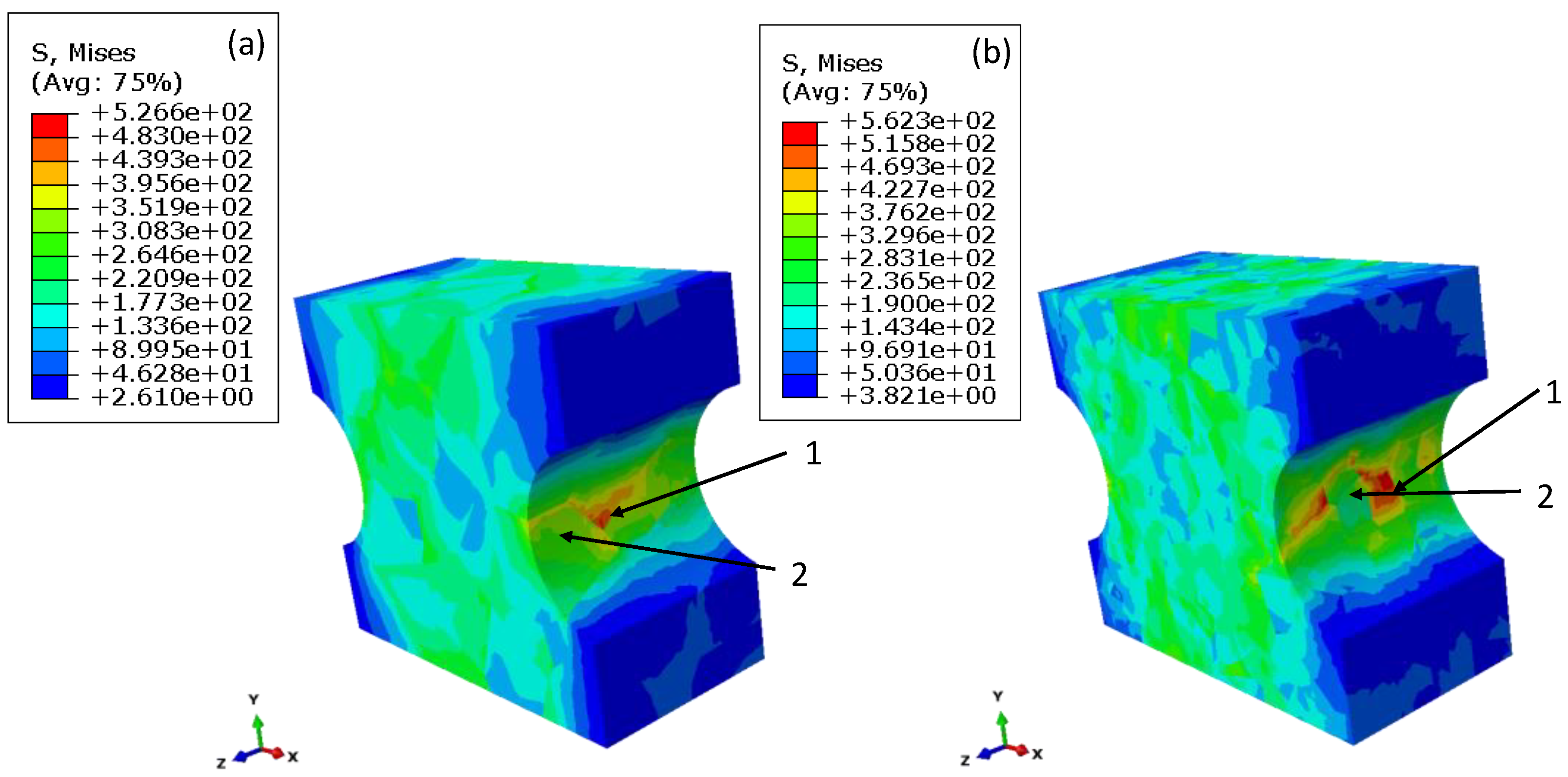
The results of the finite element analysis for the polycrystalline notched specimen at 850 °C and an applied total strain of 0.1% will be presented in the following. Figure 11 shows the distribution of the von Mises stress for a model with coarse-grain material (100 grains, random orientation distribution) and a model with the fine-grain textured material (1000 grains).
It can be clearly seen that compared to an isotropic approach the stress distribution is highly inhomogeneous within the notch area, as well as in the bulk material caused by grains with different orientations and therefore varying elastic properties. Within the notch root local maxima of stress, located close to grain boundaries, areas that 1 indicate can be found. At the same time, areas with significantly reduced stresses can occur even in the notch root (areas 2). A statistical evaluation of all simulations revealed that, on average, the maximum von Mises stress for the coarse-grained and randomly orientated specimen is 508 ± 58 MPa (evaluated from 12 simulations). The average maximum von Mises stress for the fine-grain and textured material is with 634 ± 45 MPa significantly increased (evaluated from nine simulations). It should be noted here that both models were calculated with the same applied total strain of 0.1% and the same material model; only the grain orientation distribution and grain numbers were different.
Comparing the von Mises stress results to the isotropic approach presented in Figure 10 reveals distinct higher von Mises stresses for the polycrystalline model. However, they appear on a much smaller scale within the notch root, whereas, for the isotropic approach, the whole notch root shows a maximum in von Mises stress.
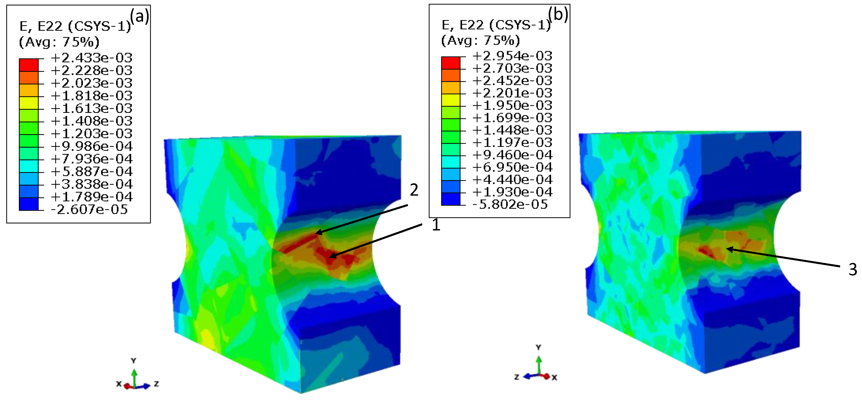
Figure 12 shows the distribution of the strain component E22 in the loading direction (y–direction) for the coarse-grain and fine-grain textured material.
Similar to the von Mises stress distribution, the strain distribution is also inhomogeneously distributed along the notch area, which results in a distinct strain scatter between 0.1% and 0.3%, where local maxima (area 1) as well as minima (area 2) can be found in the notch root. Moreover, some models show, in contrast to isotropic calculated models, that strain maxima can also occur outside the notch root, as area 3 shows. For all nine calculated models, the maximum strain E22 in loading direction for the fine-grain textured material is slightly higher with 0.279 ± 0.015% than for the coarse-grain randomly orientated material with 0.271 ± 0.033% (12 models).
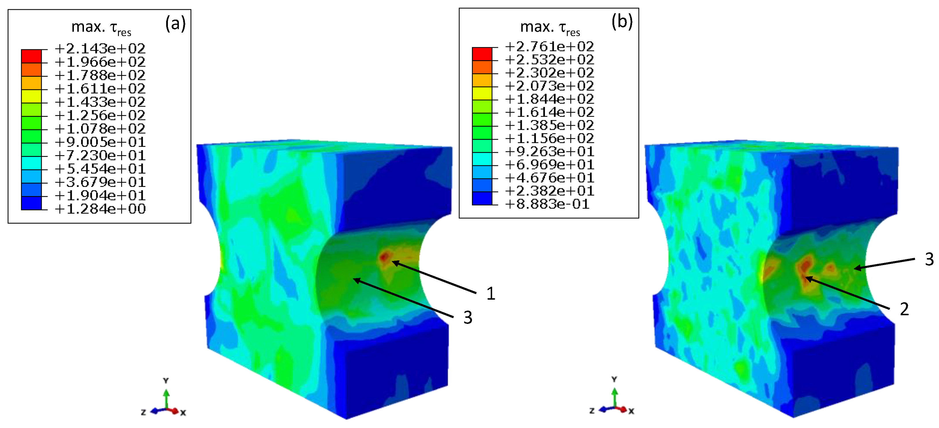
The calculation of the resulting shear stress distribution is carried out with the python tool mentioned in Section 3.2. Figure 13 shows the distribution of the maxima in the resulting shear stress within the slip system of the grains and gives an indication of where plastic deformation, and therefore fatigue crack initiation, occurs favourably.
Due to the inhomogeneous distribution of stresses and strains within the notch, caused by the polycrystalline modelling approach, the maximum resulting shear stresses are also inhomogeneously distributed. Local maxima can be found within the notch root (area 2) and also outside the notch root (see area 1). Since the shear stress distribution also depends on the stress distribution, areas with low shear stresses can also be found in the notch root, as shown for the areas 3. In these areas, a predominantly elastic deformation occurs, whereas plastic deformation can be expected first in the areas with high resulting shear stresses. Figure 13 already reveals local higher-shear stresses for the fine-grain textured material which can be confirmed for all simulations. The average value for the maximum resulting shear stress is 287 ± 9.8 MPa for the fine-grained textured material, while the average value for the coarse-grain randomly orientated material is 236 ± 26 MPa.
In conclusion, the notched models with a fine-grain textured material reveal, on average, higher mechanical properties, i.e., stress, strains and shear stresses, compared to notched models with a random orientation distribution (coarse-grain) for the same loading condition.

4.5. Shear Stress Distribution of the Smooth Specimen

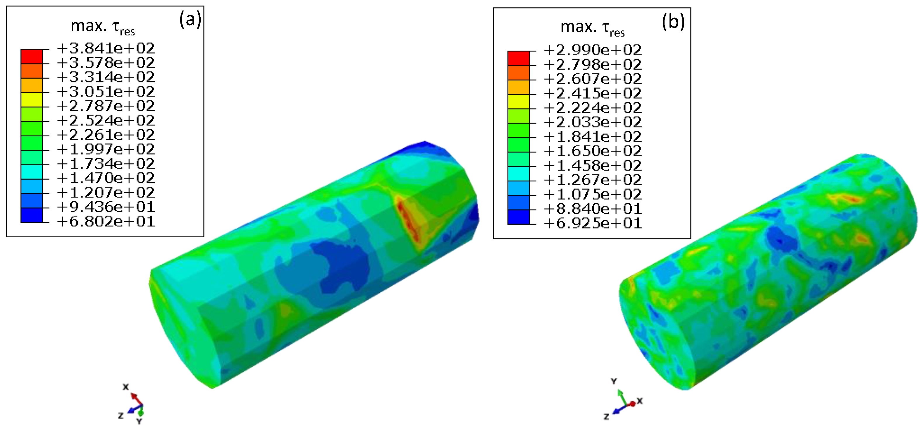
In addition to [17], further smooth-specimen simulations were carried out in order to increase the database. Figure 14 shows the distribution of shear stress for coarse-grain and fine-grain textured models at 850 °C and an applied total strain of 0.25%.
For the simulation of the smooth specimen, areas with low resulting shear stress as well as areas with locally significant increased shear stresses occurring on the surface can be clearly seen. An evaluation of the average maximum resulting shear stress of all calculated models (including the results from [17]) shows, for the coarse-grain, random orientated specimen, an average resulting shear stress of 397 ± 25 MPa. The average value for fine-grain textured material is clearly lower with about 315 ± 21 MPa.
A summary of the finite element simulations reveals for the fine-grain textured material higher local mechanical properties (stress, strain and shear stresses) when compared to the coarse-grain material for the case of a notched specimen. Interestingly, in the case of a smooth sample, the fine-grain textured material led to distinct lower mechanical properties. The following section will explain where these differences in mechanical behaviour result from and how they affect the fatigue behaviour.

5. Discussion

A general difference of lifetime behaviour between the smooth and notched specimen can be statistically attributed to the size effect. For the smooth specimen, the possible area for crack initiation, i.e., the gauge section surface, is about 6.5 (the whole surface of the notch) times higher for the notched specimen. However, just around a third of the notch surface lies within the notch root; therefore, the surface relation between the notched and smooth specimen where fatigue crack probably occurs is much higher. Despite more grains on the surface of the fine-grain textured smooth specimen which from a statistical aspect should increase the possibility of a crack initiation, a longer lifetime can be observed for the same total strains in comparison to the coarse-grain smooth specimen. The reason lies in the preferred orientation of the grains in combination with the global uniaxial stress state. This results in lower Young’s moduli of the specimen compared to a randomly orientated material. It follows for strain-controlled test conditions, lower stress amplitudes and lower shear stresses within the slip systems and therefore longer lifetimes [17]. A significantly improved lifetime of the fine-grain textured material, however, cannot be determined for the notched samples. Due to the multiaxial character of the notch and the resulting multiaxial stress states, an evaluation of Young’s moduli as a ratio of stress and strain in loading direction is not appropriate. To determine the influence of stiffness by using finite element, the reaction forces in the loading direction of all nodes were calculated and summarized to calculate the resulting force on the specimen caused by the displacement of 0.1%. Related to the cross section within the notch, the averaged nominal stress which occurs for a displacement of 0.1% for the fine-grain textured material is 240 ± 1.5 MPa. For the randomly orientated coarse-grain material, the average stress in the notch can be calculated to 190 ± 7 MPa. It could be assumed here that, for the coarse-grain material, an insufficient number of grains with perhaps stiff orientations could influence the results. As mentioned in [28], a minimum of six to eight grains are required within the cross section to minimize the influence of different grain orientations. For the coarse-grain notched specimen, more than 10 grains are located in the cross section of the notch for every model. In addition, the number of simulations (12 in total) with random grain orientation distributions, generated with the Haar measure, ensures a sufficient amount of data to provide secure statistical evaluations.
Thus, the averaged values reveal a general higher stress required for the textured material to achieve a total strain of 0.1% than for the randomly oriented material. Therefore, the notched specimens show a contrary behaviour to the smooth specimens with regard to stiffness. Since all models, notched and smooth, were calculated with the same material models as well as orientation distribution, the main the differences in mechanical behaviour can be attributed to the influence of the notch.

5.1. Development of Stiffness along the Notch

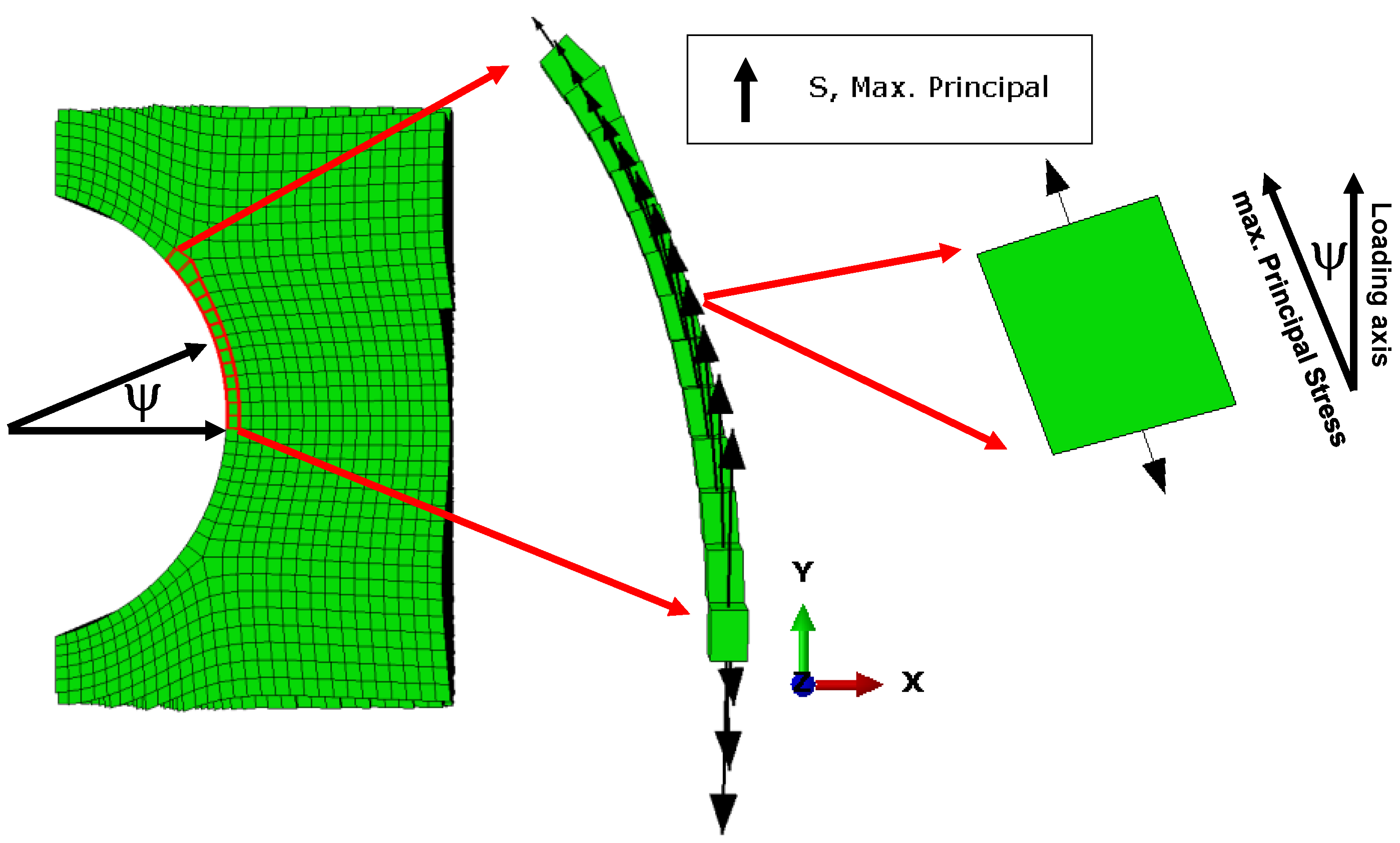
The following section explains where the stiffness differences arise from by investigating the elements of the finite elements models and assuming that elements can have different elastic properties due to their local orientation in relation to the loading axis. For all the explanations given below, an anisotropic material behaviour is assumed due to the texture and differences in the alignment of the grains (i.e., elements) between the local principal stress axis and loading axis, but the microstructure of the material is assumed to be homogenous (non-consideration of grains). Therefore, a grain interaction caused by differently shaped and orientated grains is not considered here. For the smooth specimen, the loading axis aligns with the axis of maximum principal stress σI for all elements (σII, σIII << σI). Assuming the determined crystallographic texture for all elements, with φ1, φ2 random and ϑ constant with 25°, the Young’s moduli, i.e., stiffness, are nearly uniformly distributed with an average value of 128 ± 0.9 GPa, calculated for 850 °C. This outcome results from Monte Carlo simulations in which a single element was rotated 10,000 times while the stiffness in loading direction (direction of maximum principal stress) was evaluated. For the notched specimen, the direction of maximum principal stress is not constant and changes for each element along the notch due to its geometry, as Figure 15 illustrates.
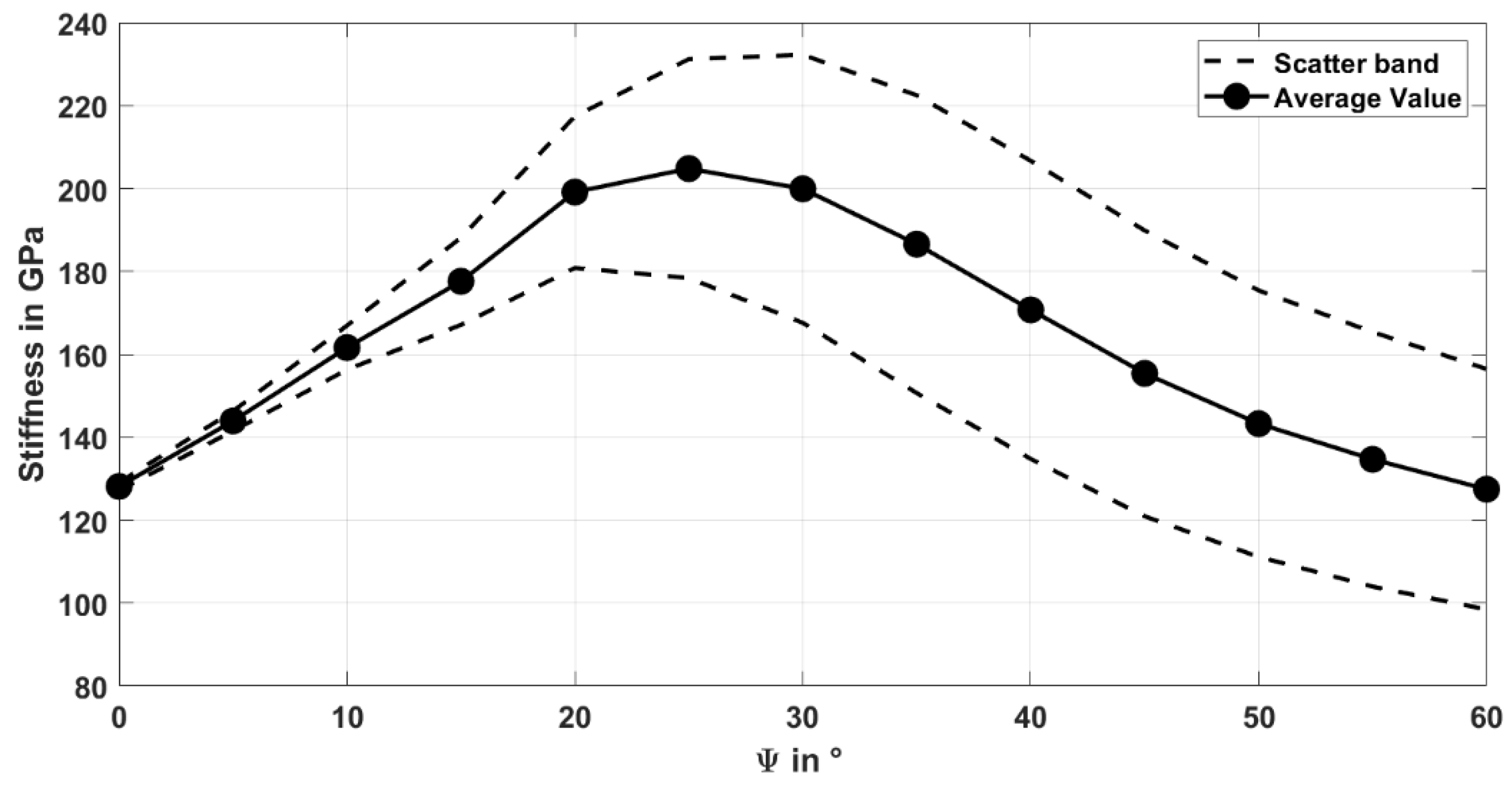
It can be clearly seen that along the notch, an angle ψ between the maximum principal stress and global loading axis forms. If now a constant texture, i.e., constant orientation of each element is assumed, the principal stress direction of the elements aligns tangentially along the notch with regard to the global loading axis y. This assumption is valid for notches with a circular or elliptical shape (no sharp notches). For elements in the notch root, the difference angle is ψ = 0° and therefore the results of the Monte Carlo simulation to determine the possible stiffness at this point are similar to the results for a uniaxial case in the smooth specimen (the direction of principal stress align with the loading direction). For calculating the stiffness for elements with angles ψ ≠ 0°, the following method was applied. Instead of calculating the stiffness for the constant texture with changing directions of the maximum principal stress (to represent the notch), the principal stress direction was kept constant, and the orientation of the elements were changed. For an angle of 5° between the loading direction and principal stress axis, the element was rotated about ψ = 5°, in such a way that the principle stress axis and global loading direction align. For the textured material with ϑ = 25° follows as the new angle ϑ + ψ = 30°. Monte Carlo simulations were carried out for angles ψ = 5°, 10°, …, 60° (3000 samples each). Figure 16 shows the development of a stiffness increase in dependence of the angle ψ for a textured orientation distribution with ϑ = 25° for all elements along the notch (φ1, φ2 = random).
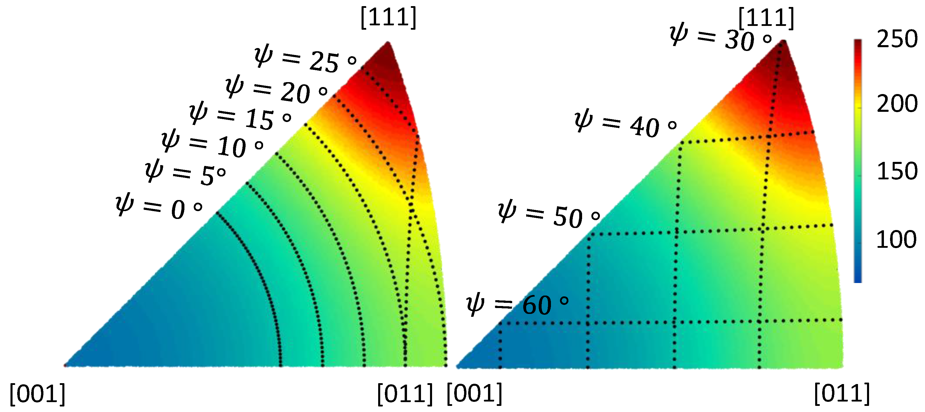
The analysis of the Monte Carlo simulation reveals an increase in stiffness until a maximum value with 200 ± 18 GPa is reached for ψ = 25° at the notch. With a further increase in ψ, the stiffness decreases with simultaneously increasing scatter, which can be explained by plotting the inverse pole figure for different angles ψ over the Young’s moduli at 850 °C, as presented in Figure 17.
Possible orientations (black dotted line) with a fixed angle of ψ = 0° (equal to the determined texture with ϑ = 25°) show low corresponding Young’s moduli and are located in a region where the Young’s moduli itself is nearly homogeneously distributed, which results in a negligible scatter. With an increase in ψ, the possible orientations cross through areas where the width of possible values for Young’s moduli increases, which also increases the scatter. As shown in Figure 16, the highest average values occur for ψ between 20° and 30°. This is due to the case that some orientations align close to the [111] axis, which result in the highest Young’s moduli values of about 250 GPa. For ψ > 30°, the scatter remains nearly constant with decreasing average value. As can be seen at the pole figures, with further increasing ψ, the possible Young’s moduli values move closer to areas close to the [100] and [110] orientations, which results in a decrease of the average Young’s moduli. For these orientations, the scatter remains quite high, since the possible orientations cross areas with a broad range of possible Young’s moduli.
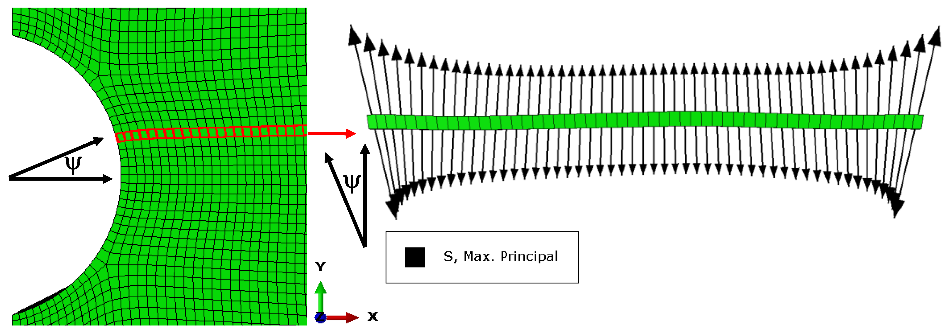
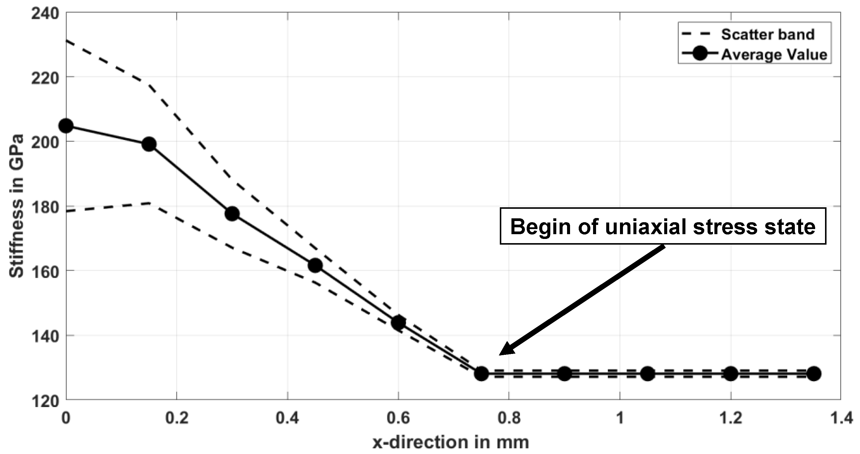
From this behaviour follows a huge stiffness discrepancy with an average 70 GPa higher stiffness at ψ = 25° compared to 128 GPa at ψ = 0°. It should be noted that this behaviour is only valid for elements on the surface of the notch root. For elements in the direction of the bulk material (x–direction), the orientation changes of principal stress are shown on a cross section through the notch in Figure 18.
For the first couple of elements close to the notch, a distinct difference angle ψ between the global loading axis y and principal stress direction can be identified. With increasing distance from the notch (in x–direction), the maximum principal stress aligns more and more with the global loading direction. Transferred to the results for the elements in the notch, a stiffness gradient follows with high stiffness at the notch root and decreasing values into the bulk material. Figure 19 shows the development of stiffness into the bulk material through a cross section calculated by Monte Carlo simulations. The cross section is taken horizontally at ψ = 25° since it is the found maximum—see Figure 16.
As can be seen on the direction of the principal stress for each chosen element in Figure 18 and Figure 19, a uniaxial stress state is already reached after a couple of elements, which is less than a millimetre into the bulk material. This can lead to high stiffness differences between the notch area and the bulk material which reach up to 104 GPa in the worst case. The majority of bulk material, on the other hand, has only low stiffness due to the predominant uniaxial stress state in combination with the examined texture (comparable to the stress state in the smooth specimen).
Interestingly, the highest resulting stiffness (associated with an angle ψ = 25°) lies still in the range of the highest stresses, calculated for the isotropic approach caused by the notch and therefore in the critical area for crack initiation. In summary, it can be stated for the notched specimen with the examined textured orientation distribution that high stiffness appears in the highly loaded and therefore critical areas of the notch due to a stiffness increase along the notch. This results in high local stresses as well as shear stresses, as seen by the finite element simulations in Section 4.3. The bulk material, where the loading direction and maximum principal stress direction align, show significantly lower stiffness due to the texture. Thus follows for the examined textured in combination with a notched specimen geometry, that the total stiffness can be seen as a composite of the low stiffness of the bulk and potentially high stiffness of the notched area.
For a real considered polycrystalline and anisotropic material, the local mechanical behaviour is much more complex. Besides the previous described differences in alignment between maximum principal stress and global loading axis caused by the geometric character of the notch, further effects occur. Especially, the interaction between grains of different sizes and orientations where resulting constraints lead to inhomogeneous stress states along the notch as well as in the bulk material, as seen in the finite element simulations. Due to the complexity, grain interactions are not considered for the evaluation of stiffness properties.

5.2. Influence of Grain Orientation Distribution on the Shear Stress in Slip Systems

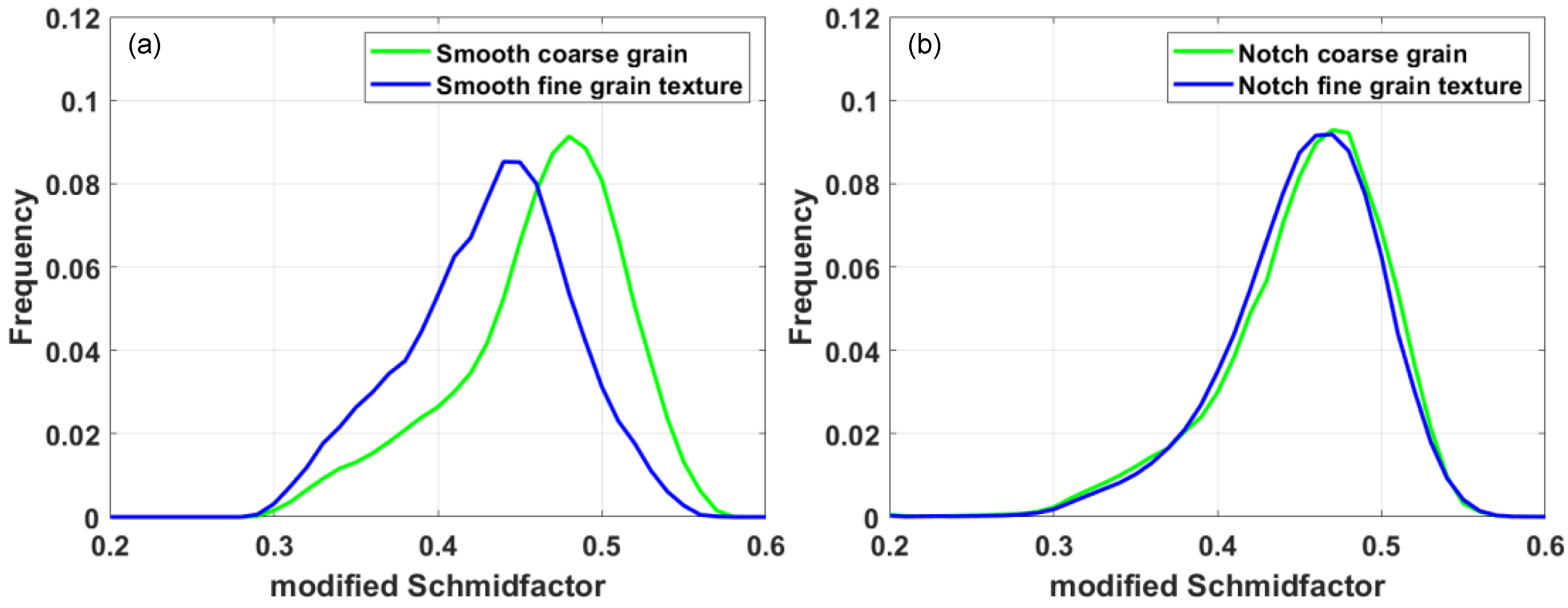
Besides the influence on stiffness, the texture of the fine-grain textured material also leads to a preferred orientation of the slip systems. To determine the onset of plasticity, the maximum resulting shear stress within the slip system was calculated according to Equation (1) and the modified Schmid factor obtained by dividing the resulting shear stress by the von Mises stress of the node. Due to the node-based formulation of the python code, the polycrystalline finite element models can be considered, whereby the local grain interaction is taken into account for the resulting shear stress evaluation. While for the smooth sample all nodes on the surface were evaluated, for the notch sample only nodes in the area of the notch root (location of possible crack initiation) were considered. Figure 20 shows the distribution of the modified Schmid factor for the smooth and notched specimen for the two different investigated grain orientation distributions.
The averaged modified Schmid factor for the smooth specimen is 0.431 ± 0.05 for the fine-grain textured material and therefore significantly lower than for the coarse-grain material with 0.468 ± 0.05. Figure 20b shows the distribution of the modified Schmid factor for all simulations carried out with a notched model. It can be clearly seen that the distributions of the modified Schmid factor show similar profiles for the notched specimen for both orientation distributions. The average modified Schmid factor for the fine-grain textured material is 0.448 ± 0.05 and nearly similar to the value for the coarse-grained randomly orientated material with 0.454 ± 0.06. The nearly similar modified Schmid factor distribution can be explained by the change of the direction of the principal stress along the notch. For the smooth specimen, the loading direction is constant and lead by the constant texture to an improvement of the modified Schmid factor. For the notched specimen, the texture is also constant, but the direction of maximum principle stress changes along the notch, which leads to a variation in Schmid factors due to constant texture with varying principal stress direction (analogue to the stiffness). Since nearly similar modified Schmid factor distributions were found for the notched specimen, the increased values of the resulting shear stress of about 50 MPa (see Figure 13) for the fine-grained textured material can be attributed to the evaluated higher stiffness along the notch root. The increased stiffness in combination with slightly higher strains (see Figure 12) leads to higher stresses in the notch root and finally to higher local shear stresses.
A slightly shorter lifetime associated with the slightly higher shear stress of the fine-grain textured and notched specimen cannot be clearly evaluated regarding the stress and strain Wöhler curves shown in Figure 5 and Figure 6. Due to the low amount of data, it is very difficult to make reliable statements about differences in lifetime due to the large scatter.

6. Conclusions and Outlook

In the present work, the influence of a random and textured grain orientation distribution on the mechanical as well as fatigue behaviour was investigated for the polycrystalline nickel-base superalloy René80. Isothermal LCF tests at 850 °C with notched specimen show a stable cyclic behaviour over the lifetime independent of the applied strain amplitude. Analogous to the fatigue behaviour of smooth specimen, low total strain leads to single crack initiation, whereas high total strain results in multi-crack initiation sites. Overall, for same total strain amplitudes, the notched specimen reveals distinct higher lifetimes compared to the smooth specimen, which can be mainly attributed to a significantly smaller highly loaded volume with distinct smaller grain numbers. In contrast to the smooth specimen, where the fine-grain textured improved the fatigue life due to lower Young’s moduli and modified Schmid factor, no improvement was found for the notched specimen. This can mainly be attributed to the development of an area with high stiffness along the notch, caused by constant grain texture with varying principal stress directions generated by the notch geometry. Under loading, this results in slightly higher stresses and therefore to higher shear stresses in the notch root area compared to the random orientated material. Since the distribution of modified Schmid factors show no differences for the notched random and textured orientated specimen, the increased shear stress results mainly from the increased stiffness development along the notch. According to minor differences in shear stress for the random and textured material with about 50 GPa, no deviations in lifetime could be observed, which can be attributed to the small number of tests as well as to the occurring scatter in lifetime.
In summary, it can be stated that the examined material texture is beneficial for uniaxial fatigue loading in combination with smooth specimens due to its improvement in elastic properties as well as the onset of plasticity. However, for notched specimens, these advantages disappear and a nearly similar fatigue behavior evolves between the textured and random-orientated material.
Using the presented modeling approach, it is furthermore possible to design grain orientation distributions which generate minima in stress as well as resulting in shear stress for complex geometries, to improve the component performance under high-temperature LCF conditions.

Author Contributions

B.E. wrote the present paper and executed the material modelling. Experimental work and analysis was carried out by B.E. and supported S.O. L.M., and T.B. were mainly involved in discussing and interpreting the results as well as in supervising the work. All authors have read and agreed to the published version of the manuscript.

Funding

The investigations were conducted as part of the joint research program COOREFLEX TURBO in the frame of AG Turbo. The work was supported by the Federal Ministry for Economic Affairs and Energy as per resolution of the German Federal Parliament under grant number 03ET7041K.

Data Availability Statement

Data not available due to commercial restrictions.

Acknowledgments

The authors gratefully acknowledge AG Turbo and Siemens AG for their support and permission to publish this paper. The responsibility for the content lies solely with its authors.

Conflicts of Interest

The authors declare no conflict of interest.

References

  1. Walsh, P.P.; Fletcher, P. Gas Turbine Performance; Blackwell Science Ltd.: Oxford, UK, 2004. [Google Scholar]
  2. Ramberg, W.; Osgood, W.R. Description of Stress-Strain Curves by Three Parameters; National Advisory Committee for Aeronautics: Edwards, CA, USA, 1943.
  3. Zhao, L.G.; Tong, J.; Vermeulen, B.; Byrne, J. On the uniaxial mechanical behaviour of an advanced nickel base superalloy at high temperature. Mech. Mater. 2001, 33, 593–600. [Google Scholar] [CrossRef]
  4. Zhang, Z.; Yu, H.; Dong, C. LCF behavior and life prediction method of a single crystal nickel-based superalloy at high temperature. Front. Mech. Eng. 2015, 10, 418–423. [Google Scholar] [CrossRef]
  5. Neidel, A.; Riesenbeck, S.; Ullrich, T.; Völker, J.; Yao, C. Hot cracking in the HAZ of laser-drilled turbine blades made from René 80. Mater. Test. 2005, 47, 553–559. [Google Scholar] [CrossRef]
  6. Siavashani, R.S.; Novinrooz, A.J.; Taherkhani, A. The Effect of Different Continuous Cooling Rates on Lattice Constant and Morphology of the Precipitates in Nickel-Base Super Alloy Rene 80. J. Basic. Appl. Sci. 2013, 3, 14–19. [Google Scholar]
  7. Donachie, M.J.; Donachie, S. Superalloys: A Technical Guide, 2nd ed.; ASM International: Russell Township, OH, USA, 2002. [Google Scholar]
  8. Kulawinski, D. Biaxial-Planare Isotherme und Thermo-Mechanische Ermüdung an polykristallinen Nickelbasis-Superlegierungen; Logos Verlag: Berlin, Germany, 2015. [Google Scholar]
  9. Holländer, D. Experimentelles Verfahren zur Charakterisierung des Einachsigen Ermüdungsverhaltens auf Basis Miniaturisierter Prüfkörper und Anwendung auf Hochtemperatur-Legierungen der Energietechnik. Ph.D. Thesis, Logos Verlag, Berlin, Germany, 2017. [Google Scholar]
  10. Moch, N. From Microscopic Models of Damage Accumulation to the Probability of Failure of Gas Turbines. Ph.D. Thesis, Universitätsbibliothek Wuppertal, Wuppertal, Germany, 2019. [Google Scholar]
  11. Schmitz, S.; Seibel, T.; Beck, T.; Rollmann, G.; Krause, R.; Gottschalk, H. A probabilistic model for LCF. Comput. Mater. Sci. 2013, 79, 584–590. [Google Scholar] [CrossRef] [Green Version]
  12. Gottschalk, H.; Schmitz, S.; Seibel, T.; Rollmann, G.; Krause, R.; Beck, T. Probabilistic Schmid factors and scatter of low cycle fatigue (LCF) life. Materialwissenschaft und Werkstofftechnik 2015, 46, 156–164. [Google Scholar] [CrossRef]
  13. Mäde, L.; Kumar, K.; Schmitz, S.; Gundavarapu, S.; Beck, T. Evaluation of component-similar rotor steel specimens with a local probabilistic approach for LCF. Fatigue Fract. Eng. Mater. Struct. 2019, 91, 319. [Google Scholar] [CrossRef]
  14. Seibel, T. Einfluss der Probengröße und der Kornorientierung auf die Lebensdauer einer polykristallinen Ni-Basislegierung bei LCF-Beanspruchung. Ph.D. Thesis, Forschungszentrum Jülich, Jülich, Germany, 2014. [Google Scholar]
  15. Mäde, L.; Schmitz, S.; Gottschalk, H.; Beck, T. Combined notch and size effect modeling in a local probabilistic approach for LCF. Comput. Mater. Sci. 2018, 142, 377–388. [Google Scholar] [CrossRef] [Green Version]
  16. Engel, B.; Beck, T.; Moch, N.; Gottschalk, H.; Schmitz, S. Effect of local anisotropy on fatigue crack initiation in a coarse grained nickel-base superalloy. In Proceedings of the 12th International Fatigue Congress (FATIGUE 2018), Poitiers, France, 27 May–1 June 2018. [Google Scholar] [CrossRef]
  17. Engel, B.; Mäde, L.; Lion, P.; Moch, N.; Gottschalk, H.; Beck, T. Probabilistic Modeling of Slip System-Based Shear Stresses and Fatigue Behavior of Coarse-Grained Ni-Base Superalloy Considering Local Grain Anisotropy and Grain Orientation. Metals 2019, 9, 813. [Google Scholar] [CrossRef] [Green Version]
  18. Engel, B.; Beck, T.; Schmitz, S. High temperatue Low Cylce Fatigue of the Ni-base Superallor René80. In Proceedings of the Eighth International Conference on Low Cycle Fatigue (LCF8), Dresden, Germany, 27–29 June 2018. [Google Scholar]
  19. Safari, J.; Nategh, S. On the heat treatment of Rene-80 nickel-base superalloy. J. Mater. Process. Technol. 2006, 176, 240–250. [Google Scholar] [CrossRef]
  20. Takaki, T.; Sakane, S.; Ohno, M.; Shibuta, Y.; Aoki, T.; Gandin, C.-A. Competitive grain growth during directional solidification of a polycrystalline binary alloy: Three-dimensional large-scale phase-field study. Materialia 2018, 1, 104–113. [Google Scholar] [CrossRef]
  21. Engel, B. Einfluss der Lokalen Kornorientierung und der Korngröße auf das Verformungs- und Ermüdungsverhalten von Nickelbasis Superlegierungen. Ph.D. Thesis, Technische Universität Kaiserslautern, Kaiserslautern, Germany, 2019. [Google Scholar]
  22. ISO International Organization for Standardization. Metallic Materials—Fatigue Testing—Axial-Strain-Controlled; ISO International Organization for Standardization: Geneva, Switzerland, 2017. [Google Scholar]
  23. Quey, R.; Dawson, P.R.; Barbe, F. Large-scale 3D random polycrystals for the finite element method: Generation, meshing and remeshing. Comput. Meth. Appl. Mech. Eng. 2011, 200, 1729–1745. [Google Scholar] [CrossRef] [Green Version]
  24. Ghazvinian, E.; Diederichs, M.S.; Quey, R. 3D random Voronoi grain-based models for simulation of brittle rock damage and fabric-guided micro-fracturing. J. Rock Mech. Geotech. Eng. 2014, 6, 506–521. [Google Scholar] [CrossRef] [Green Version]
  25. Quey, R.; Renversade, L. Optimal polyhedral description of 3D polycrystals: Method and application to statistical and synchrotron X-ray diffraction data. Comput. Meth. Appl. Mech. Eng. 2018, 330, 308–333. [Google Scholar] [CrossRef] [Green Version]
  26. Hermann, W.; Sockel, H.G.; Han, J.; Bertram, A. Elastic Properties and Determination of Elastic Constants of Nickel-Base Superalloys by a Free-Free Beam Technique. In Proceedings of the Eighth International Symposium on Superalloys, Champion, PA, USA, 22–26 September 1996; pp. 229–238. [Google Scholar]
  27. Gollmer, M. Schadensakkumulationsverhalten der Superlegierung René 80 unter Zweistufiger Low Cycle Fatigue Beanspruchung. Ph.D. Thesis, Technische Universität Kaiserslautern, Kaiserslautern, Germany, 2018. [Google Scholar]
  28. Hyde, T.H.; Sun, W.; Williams, J.A. Requirements for and use of miniature test specimens to provide mechanical and creep properties of materials: A review. Int. Mater. Rev. 2007, 52, 213–255. [Google Scholar] [CrossRef]
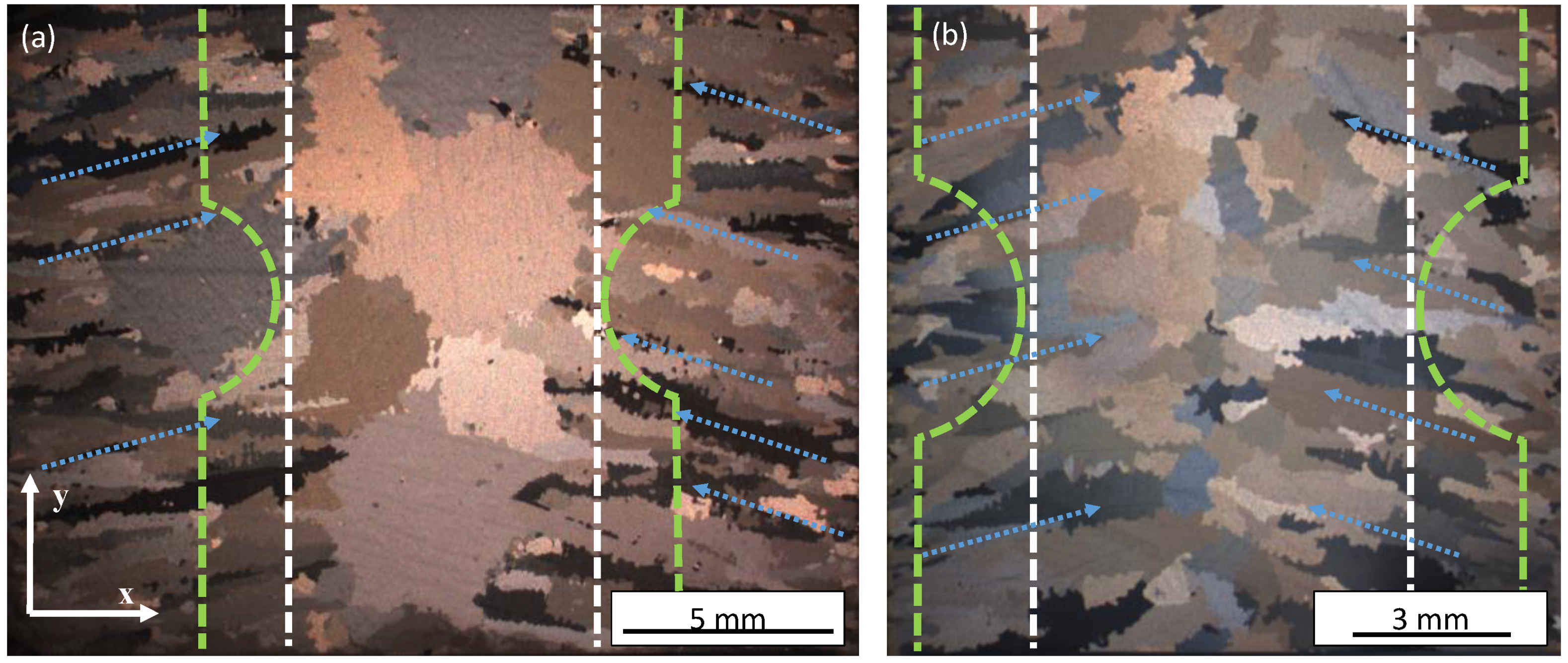
Figure 1. Longitudinal cut of the 20 mm bar (a) and 12 mm bar (b).
Metals 11 00731 g001
Figure 2. Geometry of the smooth (a) and notched (b) specimen in accordance to [14,21].
Metals 11 00731 g002
Figure 3. Normalized relationship between the global strain at the extensometer εglobal and the local strain at the notch root εnotch for the coarse- and fine-grain textured material.
Metals 11 00731 g003
Figure 4. Polycrystalline models of the notched specimen, coarse-grain with 100 grains (a), fine grain with 1000 grains (b).
Metals 11 00731 g004
Figure 5. Total strain amplitude Wöhler curve for smooth and notched specimen with different grain orientation distributions for isothermal LCF tests at 850 °C.
Metals 11 00731 g005
Figure 6. Stress amplitude Wöhler curve for smooth and notched specimen with different grain orientation distributions.
Metals 11 00731 g006
Figure 7. Fatigue and residual fracture surface of a notched specimen.
Metals 11 00731 g007
Figure 8. Crack initiation sites of a notched specimen fatigued with (a) low total strain amplitude, (b) high total strain amplitude at 850 °C.
Metals 11 00731 g008
Figure 9. Development of stress amplitude over lifetime during strain-controlled LCF testing at 850 °C for coarse-grain and fine-grain textured material.
Metals 11 00731 g009
Figure 10. Isotropic elastic simulation coarse-grain (a) material and for the fine-grain textured material (b), using a Ramberg–Osgood approach.
Metals 11 00731 g010
Figure 11. Distribution of von Mises stress for notched specimen for the coarse-grain material (100 grains, (a)) and fine-grained textured material (1000 grains, (b)).
Metals 11 00731 g011
Figure 12. Distribution of the strain component E22 in loading direction for notched specimen for the coarse-grain material (100 grains, (a)) and fine-grained textured material (1000 grains, (b)).
Metals 11 00731 g012
Figure 13. Distribution of the maximum shear stress within the slip system of the grains for the coarse-grain material (100 grains, (a)) and fine-grained textured material (1000 grains, (b)).
Metals 11 00731 g013
Figure 14. Distribution of the maximum shear stress within the slip system for smooth specimen with coarse-grain material (49 grains, (a)) and fine-grained textured material (500 grains, (b)).
Metals 11 00731 g014
Figure 15. Directions of maximum principle stress along the notch compared to loading direction y.
Metals 11 00731 g015
Figure 16. Development of stiffness along the notch for the textured material.
Metals 11 00731 g016
Figure 17. Inverse pole figure plot for different orientation distributions with constant value of ψ over the Young’s moduli at 850 °C.
Metals 11 00731 g017
Figure 18. Cross section of elements through the notch with directions of principle stress.
Metals 11 00731 g018
Figure 19. Development of stiffness into the bulk material for the fine-grain textured material.
Metals 11 00731 g019
Figure 20. Distribution of modified Schmid factor for random-orientated coarse-grain and fine-grain textured smooth (a) (according to [17]) and notched specimen (b).
Metals 11 00731 g020
Table 1. Composition of René80 in wt.%.
ElementNiCrCoTiMoWAlCBZr
René80Bal.14.049.485.084.034.022.930.170.0150.011
Table 2. Overview of the different numerical simulations.
Specimen TypeNumber of GrainsGrain Orientation DistributionNumber of Models with Different Grain MorphologiesNumber of Simulations per Model
Notched, flat100coarse random43
Notched, flat1000fine textured33
Smooth, round49coarse random61
Smooth, round500fine textured61
Publisher’s Note: MDPI stays neutral with regard to jurisdictional claims in published maps and institutional affiliations.