Abstract
Several studies on asymmetric rolling processes use the Finite Element Method (FEM) to predict material deformation and optimize process parameters, such as rolls’ forces and torques. Early studies focused on the observation and measure of curvature effects due to the asymmetric conditions. However, these models could not predict mechanical behavior associated with the texture evolution during the rolling processes. More recent studies introduced crystal plasticity (CP) models into the FEM to analyze and quantify the texture evolution during plastic forming. However, these coupled techniques need more investigation, especially concerning the mechanical behavior of the material during and after multi-stage ASR procedures. The purpose of this work is to present an up-to-date literature review on the implementation of asymmetric rolling processes in finite element analysis. It shows a summarized overview of the asymmetric rolling model parameters from different authors and gives a brief description of the crystallographic models used in their studies. In the end, some suggestions for future work dedicated to the analysis of ASR through FEM are given.
1. Introduction
The Finite Element Method (FEM) is an essential tool to predict phenomena during the manufacture and common usage of everyday objects. It enables the investigation of fracture mechanics, fluid mechanics, biomechanics, and heat conduction, among other fields. This technique requires a significant amount of time creating, computing, and analyzing models. However, in metal forming, the results from a good analysis significantly reduce the calibrating phase, typically by trial and error, translating into an overall time and cost reduction. Additionally, the parts and processes addressed by the FEM may include great complexity, which would be almost impossible to treat analytically. One of the processes that the FEM can simulate is metal rolling, which consists of passing a stock of metal between a pair (or more, in case of multistep rolling) of rolls to reduce the thickness. The simplified model represents one-quarter of the real problem by applying two symmetry conditions—one in the mid-width plane and the other in the mid-thickness plane of the rolled stock. This last condition guarantees that the roll diameter, angular velocity, and friction at the roll-stock interface are the same for the top and bottom rolls. Nevertheless, the actual production process cannot ensure the symmetry condition leading to undesirable curvature of the metal stock at the roll exit.
In 1988, Shivpuri and coworkers [1] used the FEM to investigate curling caused by the rolls’ velocities mismatch. They used an explicit time integration elastic-plastic finite element method implemented on Dyna East Finite Element Lagrangian (DEFEL) code. The results were reasonably in agreement with experimental data from the literature. However, slight discrepancies in curvature could be associated with frictional asymmetries not considered on the computational model.
A few years later, Dyja and coworkers [2] performed a numerical study on the curvature obtained by an asymmetric rolling process based on a coupled finite element method with a general diffusion equation. This approach considered the temperature effects on the deformation zone. Most of the literature acknowledges the causes of asymmetry: different radii, speeds, and friction coefficients. However, the entry angle is also an important parameter when bending is concerned. Their study showed that it is possible to reduce bending considerably by adjusting the process parameters: the entry angle, the plate temperature, reducing the friction coefficient, and the roll velocities ratio. The results aided in designing and constructing an industrial rolling mill. The final plates presented quality improvements at a lower cost.
Richelsen [3,4] performed a numerical analysis on an asymmetric plate rolling process by employing an elastic-viscoplastic finite element method with a plane-strain condition. The aim was to study the curvature due to different friction stresses at the interfaces between the plate and the rolls. The results showed that the plate would bend towards the roll with the highest friction.
Since curling will result in dimensional non-compliance in flat stock production, may harm operating personnel, and damage machinery, several published papers give significant attention to metal curvature during rolling processes. Lin and Shen [5] developed a coupled thermo-elastic-plastic finite element model of non-isothermal rolling for 3D analysis of aluminum strip curvature originated by different heat transfer conditions of the top and bottom rolls. They showed that non-symmetrical heat transfer boundary conditions caused non-symmetrical rolling forces of the top and bottom rolls with subsequent strip bending. They corrected this issue by mismatching the angular velocities of the rolls.
In 1999, Hwang and coworkers [6] used the commercial software DEFORM to perform finite element analysis on cold asymmetrically rolled aluminum sheets. They applied different roll radius ratios, roll speed ratios, and friction coefficient ratios to study the curvature of the sheets after rolling and the separating force of the rolls. Furthermore, they tested several thickness reductions and compared the numerical results with experimental trials.
Knight and coworkers [7] investigated a similar correction on the strip curvature of a hot-rolled low-carbon steel strip by performing trials. However, they only found a slight improvement on pass 4 with a velocity mismatch of −5%, meaning a decrease of 5% in angular velocity of the bottom roll. Moreover, they built an elastic-plastic finite element model that considered temperature differentials, different roll velocities, and different friction conditions. Nevertheless, accurate results in numerical analysis rely on properly defined material model input. Hot rolling is a complex process, dependent on both strain rate and temperature. Thus, they had to include in the model experimental stress–strain curves at different strain rates and temperatures. The visible curvature results predicted by the FEM agreed with the observations of the experiments. The strip turned away from the surface with higher temperature in both cases. The authors noticed that other characteristics could not be comparable because the numerical model did not incorporate temperature differences on the top and bottom surfaces of the slab. These differences might be due to descaling sprays or heat furnace inefficiency.
Lu and coworkers [8] also studied the curvature path of asymmetrically rolled steel sheets using the FEM. Their work covered different initial thicknesses and reductions when rolls’ diameters mismatch. The results showed that sheets with higher thickness would bend downwards, which corresponds to a smaller roll diameter. On the other hand, higher values of thickness reduction would make the sheet bend upwards following the largest roll diameter, which indicates that the reduction has more significant influence than the initial thickness. Additionally, they observed that the roll average radius has more impact on thinner sheets.
Lee and Lee [9] studied the multi-stage asymmetric hot-rolling process of steel sheets by mismatching the speed or the radii of the rolls. The deformation results from the FE analysis were used to predict the deformation textures by a full constraint Taylor model.
In 2002, Salimi and Sassani [10] developed an analytical model based on the slab method to determine the rolling force, torque, and strip curvature, considering the plane strain condition. Furthermore, rolls with different diameters imposed an asymmetry to the rolling process. A comparison between the analytical and numerical results showed good agreement.
On the same subject, Farhat-Nia and coworkers [11] used an elastic-plastic arbitrary Lagrangian-Eulerian (ALE) 2D finite element method to predict curvature development. They applied asymmetry to three models by mismatching the roll speeds and friction coefficients in the roll-plate interface and used an isotropic hardening law to describe the material. Once again, numerical results showed that adjustments in the roll speed might reduce the strip curvature. Existing data from literature validated the models.
In 2007, Mousavi and coworkers [12] used the finite element commercial software ABAQUS/Explicit to conduct simulations of symmetric and asymmetric cold rolling of aluminum sheets. They used the Hollomon hardening law to describe the behavior of sheets. Their study pointed out that the angular velocity ratios influenced the rolling force, rolling torque, and pressure on the rolls. Moreover, the sheet thickness before rolling and further reductions affected curvature at the roll exit. The results indicated that it was possible to obtain a flat sheet with a velocity ratio of 1.11 with equal diameter rolls.
Despite the unwanted bending response during metal rolling, the asymmetric rolling process offers enhanced mechanical properties. Hence, several studies invested in more sophisticated finite element models to discuss and evaluate shear deformation. In metal forming, the evolving textures during plastic deformation might interfere with the plastic anisotropy. As a result, the mechanical behavior of the material changes as well as its constitutive laws.
In 2004, J.-K. Kim and coworkers [13] resorted to a 2D finite element model to investigate the strain state and complement experiments on aluminum alloy 1100 sheets. The asymmetric rolling induced a significant thickness reduction per pass, and the friction coefficient ought to mimic a non-lubricated state. Findings showed that, at the rolling gap, the shear strain rate varies through the sheet thickness.
Kim and Lee [14] implemented an elastoplastic finite element model to analyze deformation and shear texture development on cold-rolled aluminum sheets. They used the strain increment history of each element to compute the crystallographic orientations. The asymmetry in deformation resulted from different diameters rolls in a multi-stage rolling. Their study showed that the ideal shear deformation texture occurred for a higher reduction per path (for a given roll radius ratio and total reduction), resulting in a higher shear-to-normal strain ratio. The results also showed that the ideal shear deformation texture only arose by reversing the rolling directions between consecutive stages.
In 2008, Tam et al. [15] indicated a lack of thorough investigation on the texture evolution of asymmetrically rolled sheets predicted by finite element simulations. For this reason, they developed a crystallographic homogenized finite element model to examine asymmetric rolling processes. The material properties introduced in the computational model resulted from uniaxial tensile tests. Furthermore, they measured the sheet metal textures by electron backscattering diffraction (EBSD) and compared the findings with finite element simulations. Although the FE model could not achieve the ideal shear texture, the authors ensured that the FEM was a comprehensive tool to predict texture evolution during metal forming processes.
In 2009, Ji and Park [16] used a rigid-viscoplastic finite element model on the commercial software DEFORM to analyze asymmetric rolling processes of steel sheets. They built six cases with different parameters and compared their results with each other regarding deformation pattern, plastic deformation, rolling pressure distribution, rolling force, and rolling torque. Their findings demonstrated that the rolling process was unstable due to slipping at the interface. They suggested the ideal model case for a rolls’ diameter ratio of 0.5, the bottom roll angular velocity of 1 rad/s, the top roll was rolling free, and a friction coefficient of 0.7 for both rolls–sheet interfaces.
Sverdlik and coworkers [17] defined an asymmetric rolling finite element model on the commercial software DEFORM to observe the plastic deformation on thin sheets. They focused on the vertical lines distortion, shear strain values at the strip cross-section and studied the influence of several thickness reductions on the deformation. Results showed the asymmetric rolling process induces shear deformations through thickness more than nine times compared to conventional rolling.
Hao and coworkers [18] used the finite element commercial software ABAQUS with the Arbitrary Lagrangian–Eulerian (ALE) adaptive meshing technique to simulate the asymmetric cold-rolling process of steel sheets. The material was considered isotropic and elastic-plastic, and an empirical stress–strain curve was added to the model. The rolls had different diameters causing the asymmetric conditions. The numerical findings were compared and validated by experimental results.
Xie and coworkers [19] presented a novel technique to investigate the surface roughness in steel sheets produced by cold rolling. The asymmetric condition was applied by mismatching the angular velocities of the rolls. The material was assumed isotropic elastic-plastic. A more flexible friction law was used, based on Peng et al. [20], where static and kinetic friction coefficients were defined (0.035 and 0.025, respectively). Furthermore, they used the finite element commercial software LS-DYNA to carry out the simulations and determine the effect of the speed ratio on the rolling force, the strip curvature, and the roughness in the rolling process.
In 2016, Pesin and Pustovoytov [21] also used software DEFORM to investigate the effect of rolls speed ratio, friction coefficients, and deformation route on the shear and effective strains of aluminum alloy 5083 during a high-ratio differential speed rolling (HRDSR) process. Their numerical model comprehended four deformation routes UD, TD, RD, and ND, in two stages. Meaning that in the UD route, the sheet kept the same direction on both stages, whereas in the TD route, the sheet was rotated 180° about the transverse direction between stages. Likewise, in the RD and ND routes, the sheet was rotated 180° about the rolling and normal directions, respectively, before the second rolling pass. Simulations showed that the effective strain doubled during asymmetric rolling with the UD route: from ε = 1.6 during symmetric rolling to ε = 3.2 during asymmetric rolling.
In the following year, Pesin and Pustovoytov [22] presented another study based on the finite element method to examine the deformation of Al-6.2Mg-0.7Mn alloy obtained by the asymmetric warm rolling process on a single-pass. They aimed to enhance deformation characteristics by finding the best parameter combination possible. The study included a different thickness reduction per pass, rolls velocity ratio, rolls diameters, and friction coefficients for several initial strip thicknesses. The model also included heat generation due to friction and plastic work. The ideal case identified was: rolls diameter of 500 mm, rolls speed ratio of 57%, a friction coefficient of 0.4, for initial thickness of 1.0 mm and 60% thickness reduction on a single-pass. The finite element method provides valuable information on the mechanical behavior during metal forming. According to the authors on this and another very similar paper [23], it can be used to optimize asymmetric rolling processes.
Taking advantage of the previous work, Pesin and coworkers [24] performed FE simulations to investigate and compare the deformation on the aluminum alloy 5083 obtained by a single-pass equal-channel angular pressing (ECAP) symmetric and asymmetric rolling processes. The ECAP is limited to small-size samples, which represents a drawback for industrial applications. On the contrary, the asymmetric rolling process demonstrates significant potential for producing large-dimensional materials with ultrafine grains.
Wroński and coworkers [25,26,27] conducted three studies using two scales models to predict deformation textures caused by the asymmetric rolling process. Experimental textures measured by X-ray diffraction validated the computational models. In 2009, they incorporated the polycrystalline deformation Leffers-Wierzbanowski (LW) model in the finite element commercial software ABAQUS to predict low carbon steel deformation textures. Moreover, they examined the curling effect in the simulations and compared them with experiments. The computational model was able to predict deformation textures and curvature accurately. In 2015, they applied the same coupled model to aluminum alloy 6061 and observed a considerable reduction in bending for a rolling asymmetry below 1.3. Additionally, results showed a more homogeneous shear texture across the thickness after asymmetric rolling, and the internal stress component Σ33 reduced its magnitude vs. rolling asymmetry, A, meaning, Σ33 is lower for A = 1.05 and A = 1.3 (asymmetric rolling) than for A = 1.0 (symmetric rolling). Consequently, the applied rolling force decreased, which is an advantage to the rolling mill’s durability. In 2017, they introduced a self-consistent elastoplastic code into the finite element model to analyze texture variation across the sample thickness with considerable detail. The results were in line with the previous ones. The asymmetric rolling process modifies the material plastic anisotropy resulting in a higher average Lankford coefficient. Moreover, they identified an asymmetry ratio of 1.1 to obtain a nearly homogeneous plastic anisotropy across the sample thickness.
Nakamachi and coworkers [28] developed a dynamic-explicit crystallographic homogenized elasto-viscoplastic finite element coupled model (two-scale FE) to optimize asymmetric warm rolling processes. They examined the plastic deformation of aluminum sheet alloy 6022 employing simulations and verified the model with experimental texture results obtained with SEM-EBSD (Scanning Electron Microscopy-Electron Backscatter Diffraction). The two-stage rolling process relied on a set of rolls of equal diameters. The difference in roll speeds of the first stage imposed the asymmetric deformation. In the second stage, the process was symmetric. Furthermore, they added a boundary condition to constraint movement in the thickness direction of a finite element node to guarantee sheet flatness during the rolling process. Concerning the material properties, they used experimental data from uniaxial tensile tests at room temperature and at 250 °C to find the parameters for Norton’s constitutive law at the macro-scale and the elastic/crystalline viscoplastic constitutive model at the micro-scale. They achieved an ideal condition for a specific roll speed ratio and thickness reduction.
Another texture evolution study during plastic deformation, presented by Kuramae and coworkers [29], used a two-scales finite element coupled model and a discrete optimization method. They used the electron backscattered diffraction to define the initial crystal orientation distribution of aluminum alloy 6022. The effect of temperature introduced into the elastic/crystalline viscoplastic constitutive equation allowed for evaluating thermal effects during multi-stage warm rolling processes. The analysis showed that warm asymmetric rolling processes produce more shear texture deformation than procedures conducted at room temperature.
In 2014, Tamimi and coworkers [30] performed a series of finite element simulations of multi-stage asymmetric rolling processes to investigate the onset and evolution of shear deformation through the sheet thickness. Besides, polycrystal simulations using a visco-plastic self-consistent (VPSC) model predicted the shear texture deformation and the deformed samples’ mechanical behavior for different simulation parameters. To avoid bending between the rolling passes, they added a boundary condition to two nodal points in the mid-thickness plane. The FE simulations showed a slight increase of shear strain on the second ASR stage. Moreover, the VPSC results revealed shear texture components, which might imply a higher plastic strain ratio. Additionally, they identified an undesirable planar anisotropy increase.
Grácio and coworkers [31] studied the mechanical, structural, and textural behavior of asymmetric-rolled AA5182 sheets. They used X-ray diffraction to measure textures in the mid-thickness of initial and rolled samples, which were used as inputs for the VPSC model and the crystal plasticity finite element method (CPFEM) to predict the crystallographic texture evolution and the mechanical response. Furthermore, the material behavior was modeled considering the anisotropic yield criteria Yld2000 [32] coupled with the M–K theory [33]. The results of conventional rolling with asymmetric and asymmetric rolling-reverse, where a roll speed mismatch imposed the asymmetry, were compared. It must be noted that asymmetric rolling-reverse means that relative speed of the upper and lower rolls shift between steps, i.e., if the angular velocity of the upper roll is higher than the angular velocity of the lower roll on the first step, on the second step, the angular velocity of the upper roll must be smaller than the angular velocity of the lower roll or vice-versa. Concerning the numerical modeling, the CPFEM used to predict the hardening curve showed a good correlation with experimental data when the curve reached the saturation zone. The predicted VPSC yield stress and r-value directionalities revealed that the strain path changes in the asymmetric rolling-reverse process produce a more isotropic material.
Shore and coworkers [34] performed a parametric study with a new anisotropic constitutive law implemented on the commercial software ABAQUS/Explicit. They introduced a FACET/ALAMEL scheme, where an analytical yield function limited to the subspace of the stress and strain rate in 2D reproduced the plastic anisotropy as a crystal plasticity model would. This approach aimed to examine the texture deformation evolution with the thickness reduction, rolls speed ratio, and roll-radius-to-sheet-thickness ratio asymmetric rolling parameters. The results indicated advantages in performing the asymmetric cold rolling in the latest stages. Furthermore, the model proved accurate predictions of the plastic anisotropy.
Yekta and coworkers [35] addressed the bending issue of the asymmetric rolling process by carrying out simulations on the commercial software ABAQUS. They used 2D models of the aluminum sheet. The asymmetric conditions were imposed by different radii or angular velocity mismatch of the rolls. The results from the simulations were compared with the experimental work of Hwang and Tzou [36] and theoretical studies of Qwamizadeh and coworkers [37].
In 2019, Feng and coworkers [38] suggested a modified formula, initially presented for the symmetric rolling process, to obtain the minimum thickness limit for different diameter single-roller-driven asymmetric rolling. Their study included a finite element simulation on the commercial software MSC.Marc to predict the deformation contour and the friction stress on the top and bottom surfaces of the cross-shear zone. The results obtained with this new approach were in good agreement with the experiments.
Zanchetta and coworkers [39] used the finite element commercial software DEFORM to quantify the strain components’ influence on asymmetric-rolled aluminum sheets. Rolls with different diameters imposed the asymmetric condition. The finite element analysis was a complement to the experimental work on texture and plastic anisotropy. They observed and compared the finite element mesh distortion with the engraved lines distortion on the laterals of the sample. Additionally, the FE simulation suggested a higher thickness reduction induced shear to the center of the sheet, whereas a lower thickness reduction increased the rigid body rotation. It is worth mentioning that a user subroutine computed the rigid body rotation of each finite element.
Godoi et al. [40] also used the software DEFORM to model a single-pass procedure to clarify and compare the strain distribution resulted from symmetric and asymmetric roll bonding. The study included microstructure and crystallographic texture measured by EBSD and X-ray diffraction. Additionally, hardness and tensile tests characterized the strain distribution and bonding efficiency. The FE simulations allowed the computation of discrete values for the shear strain εxz and compression strain εzz, where x, y, and z axes corresponded to rolling, transverse, and normal directions, respectively.
In 2020, Kraner et al. [41] performed finite element simulations on the commercial software ABAQUS/Explicit to compare symmetric and asymmetric rolling processes on aluminum sheets. The model parameters were representative of the rolling procedures tested in a laboratory. They observed the bending effect due to the asymmetric condition (both simulated and experimental) and called it the ski effect. The authors presented a comprehensive discussion on the FE results. They stated that for the same roll gap, the asymmetric rolling process resulted in thinner plates and that the asymmetric procedure was faster than the symmetric one.
In hot-rolling processes, dynamic recrystallization (DRX) has a decisive influence on grain refinement. Zhang and coworkers [42] applied coupled FE–microstructure evolution models to predict the microstructure evolution of asymmetric-rolled aluminum plates. They used an empirical model to determine the DRX fraction and grain size components, where the strain, the strain rate, and the temperature are the independent variables. The formulation of the constitutive equation, derived from the Arrhenius equation, was presented in a previous work of Zhang and coworkers [43]. Furthermore, they compared experimental and simulated average grain size. Simulations were carried out by the FEM and by the cellular automata (CA) model. The results from the CA model had better agreement with the experiments than the FE results.
At this point, all the selected papers focused on the finite element analysis for asymmetric rolling of aluminum and steel. There are substantial more studies concerning the experimental aspects of the asymmetric rolling process that Vincze and coworkers reviewed in a recent paper [44]. In 2020, Kraner et al. [45] presented a brief review on the asymmetric rolling process focusing on the possibility of industrial manufacture. Additionally, numerical studies on other materials such as magnesium, titanium and copper alloys, and silver can be found in [46,47,48,49,50,51,52].
Although the numerous published papers on asymmetric rolling, there are few dedicated to thin strip rolling to the authors’ knowledge. For example, in works [14,17,30], the initial thickness values are from 1.2 to 3 mm and reduced by 50% and 80% after de ASR process. Only in the study of Feng and coworkers [38], the initial thickness is less than 1 mm. Jiang and Tieu [53] simulated the rolling process of the thin strip using the finite element method. According to them, a suitable friction variation model is required for a good agreement between experimental and simulation results. However, no asymmetry condition was applied to the model. Similarly, Ren and coworkers [54] presented experimental and numerical analysis for ultra-thin strip rolled steel (with 0.3 mm and 0.1 mm thickness of the hard and soft strips, respectively) using symmetric rolling conditions. They proposed a simplified Fleck model for modeling rolling of the thin strip that has been validated for the measure of the rolling force.
2. Finite Element Analysis Applied to Asymmetric Rolling Processes
The purpose of Finite Element Analysis (FEA) software is to assist in the conception and optimization of devices and processes. Once the numerical model is validated, it becomes possible to better understand real-life situations and responses that can lead to significant improvements to a design or process. Most commercial FEA software products feature user-friendly interfaces and include predefined models that help reduce the time preparing a FE simulation. An FEA is divided into three stages, namely: preprocessing, simulation, and postprocessing. The tasks in the preprocessing phase are:
- build the geometrical model;
- assign the material properties;
- define time steps;
- enforce boundary conditions;
- discretize the problem domain.
The preprocessing phase is crucial to obtain accurate results. It requires domain expertise to define the geometric model, material properties, and simulation parameters. Next, the stages and tasks of the FEA will be briefly described in the context of the asymmetric rolling process, and inputs from different research works will be presented.
2.1. Build the Geometrical Model
The geometrical model for the rolling process consists of a pair (or more) of rolls placed according to the required thickness reduction and a workpiece. Figure 1 shows three examples of geometrical models. Figure 1a,c represent single- and multi-pass rolling processes, respectively. Figure 1b shows a model with different rolls’ diameters which will result in an ASR process. Figure 1d is a workpiece representation. Table 1 comprises values for workpiece and rolls dimensions used in several ASR studies. Table 1 also includes the number of rolling passes and the thickness reduction associated with the rolls’ gap. The reduction values presented as v1:v2:v3 mean that different values were used, starting on v1 and ending on v3 with steps by increments of v2. For example, 10:20:80 indicate reductions of 10%, 20%, 40%, 60%, and 80%. The designation “var” indicates that various values were used for a specific parameter.
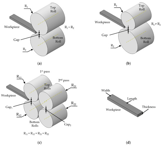
Figure 1.
Geometrical models representation. (a) A single-pass rolling process; (b) A single-pass ASR process due to rolls’ diameters mismatch; (c) A two-pass rolling process; (d) Workpiece measurements.

Table 1.
Geometrical model parameters used in ASR simulations by different authors.
For the sake of comparison, the boundary conditions discussed in Section 2.4 are also included in Table 1.
2.2. Assign the Material Properties
This task concerns the definition of material properties such as density, the elastic parameters Young’s modulus and Poisson’s coefficient, the stress–strain curve for the plastic behavior, thermal and electrical conductivity, among other properties. For more complex models, users can implement specific subroutines. Additionally, software products specialized in plastic deformation (e.g., QFORM, DEFORM, and SIMUFACT) have extensive material databases, making it an effortless and quicker task.
Moreover, the von Mises isotropic yield criterion is well established and most used to model materials. For example, it can be found in the ASR studies [2,8,11]. Nevertheless, anisotropic yield criteria may also be applied. Lin and Shen [5] used the Prandt–Reuss model, Shore and coworkers [34,56] used a facet yield function, and Grácio et al. [31] selected the Yld2000-2d criterion.
Table 2 shows the material properties used by different authors in their ASR studies. It indicates the name of the material, the temperature of the workpiece at the beginning of the simulation, where RT means Room Temperature, density (), Young’s modulus (E), Poisson’s ratio (), the true stress–strain constitutive law (), where and are the effective stress and effective strain, respectively, I is the identity matrix, and is the strain rate. Table 2 also contains parameters for crystal plasticity models such as the critical initial resolved shear stress (), the hardening exponent (n), the initial hardening modulus (h0), the hardening coefficient (C), and the initial accumulated shear strain (). Studies without crystal plasticity models show a not applicable note (n/a).
Table 2.
Material properties used in ASR simulations by different authors.
2.3. Define Time Steps
The step definition accounts for the type of analysis procedure, such as static/dynamic or implicit/explicit analysis, and the time increments needed to solve the governing equations.
2.4. Enforce Boundary Conditions
This task is necessary to define the constraints, loads, and interactions (contact) applied to the model. The rolls have a single degree of freedom which is rotation around its axis, and it is defined as an angular velocity. A friction law describes the interaction between the surfaces of the rolls and the workpiece with the corresponding friction coefficients. The Coulomb’s or constant shear friction models are commonly employed, but there are other possibilities. Gudur and coworkers [57] used Wanheim and Bay’s friction model [58] to estimate the friction coefficient by measuring the strip curvature in an asymmetric rolling process. Details regarding the friction modelling in metal forming can be found in the review paper of Nielsen and Bay [59]. The workpiece has an initial linear velocity coincident with the rolling direction to ensure the initialization of the procedure. The model can be assumed symmetric in the RD–ND plane (rolling direction–normal direction). Assuming rolls with the same radius (R1 = R2), asymmetric deformation occurs when the angular velocities of the top and bottom rolls differ (ω1 ≠ ω2) or when the friction in the rolls-workpiece interfaces are different (μ1 ≠ μ2). Figure 2a represents both ω1 ≠ ω2 and μ1 ≠ μ2 conditions. As can be noticed, the workpiece shows a slight curvature at the rolls’ exit.
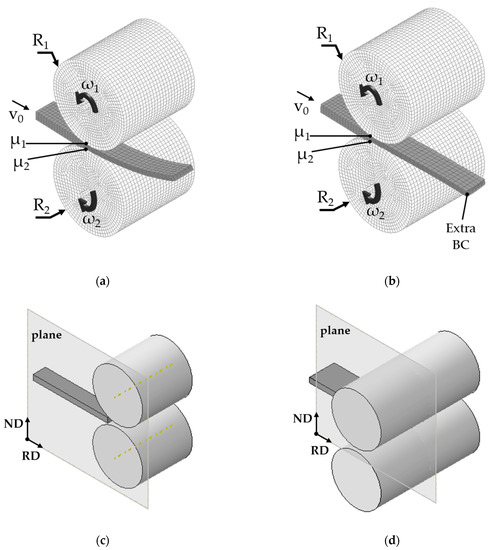
Figure 2.
Boundary conditions imposed to accomplish ASR results. (a) A schematic of velocities and friction BC; (b) An illustration of the additional BC to avoid bending; (c) Symmetry plane RD–ND; (d) Geometrical model without considering symmetry in the RD–ND plane.
For a multi-pass analysis, an additional boundary condition restraining the displacement in the thickness direction will guarantee the flatness of the workpiece between stages. For example, Nakamachi and coworkers [21] add the extra boundary condition (BC) to a single node, as illustrated in Figure 2b. Lastly, Figure 2c represents the symmetric condition in the RD–ND plane, and Figure 2d shows the model without considering symmetry.
As mentioned previously, the boundary conditions that affect the ASR process are the rolls’ angular velocities and the friction coefficients that characterize the workpiece-roll interface. Values for these BC are shown in Table 1.
Another aspect to consider in multi-pass ARS processes is the route of the workpiece in the different stages. After the first rolling pass, the workpiece may be rotated before entering the next rolling pass. Table 3 shows four workpiece rotations worth of investigations (it must be noted that it is only a schematic and does not account for the deformation experienced in the first rolling stage). In the first case, the workpiece maintains its orientation. In the second case, the workpiece rotates 180° about the transversal direction. In the third and fourth cases, the workpiece rotates 180° about the rolling and normal directions, respectively. These studies are essential because the mechanical properties of rolled metal sheets strongly depend on the deformation path history.
Table 3.
Deformation routes in a two-pass ASR process.
2.5. Discretize the Problem Domain
In this task, the user discretizes the model into small elements in which the solver calculates the unknown variables. Then, the results of the entire model are the sum of the estimations of each element. The type of element chosen must be according to the kind of analysis, and the mesh size must ensure accurate results without taking too much computing time. It is good practice to do a mesh convergence study when there is no certainty how refined the mesh should be for the stated problem. Table 4 shows the type of element and mesh size used in ASR simulations by different authors. This table also mentions commercial FEA software and constitutive models. For studies with FE crystallographic analysis, where the problem is discretized at the crystal level, Table 4 also indicates the number of grains selected. Next, the FE models that include crystallographic approaches are briefly described.
Table 4.
FEM models, mesh parameters, and commercial software used in ASR simulations by different authors.
2.6. Crystallographic Models
2.6.1. Crystallographic Homogenized Model
The dynamic-explicit crystallographic homogenized elasto-viscoplastic finite element coupled model for the asymmetric rolling process, applied by Tam, Nakamachi, Kuramae, and coworkers [15,28,29], consists of a two-scale finite element approach in which both the macro-continuum and the micro-crystal structure are discretized. Figure 3a shows the macro-continuum structure, Ω. As can be noticed, there are boundary conditions and loads applied and a coordinate system to represent all measurements associated with the macro-scale. On the other hand, the macro-continuum structure incorporates the micro-polycrystal structure, Y, represented in Figure 3b. From Y, it is possible to highlight the Representative Volume Element (RVE), shown in Figure 3c, which embodies a polycrystal aggregation of well-defined grains. The RVE is much smaller than the macro-continuum structure, Ω, by the scale factor λ<<1. Figure 3d shows the crystal lattice for faced-centered cubic (FCC) structure materials.
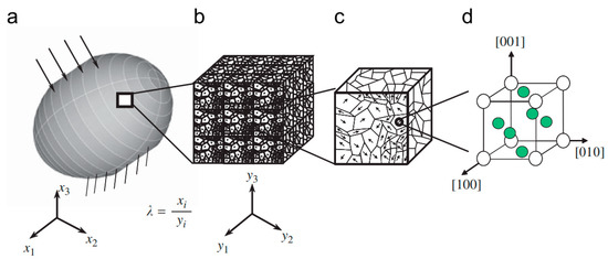
Figure 3.
Double scale structures, coordinates, RVE, and FCC crystal lattice structure. (a) The macro-continuum; (b) The micro-polycrystal structure; (c) RVE; (d) Crystal lattice. (Reproduced from [28], with permission from Elsevier, 2009).
The kinematics at two scales concerns the definition of velocities at the micro- and macroscopic levels to derive the equations for the model. They used the updated Lagrange formulation approach for the virtual power principle and the homogenization method to contemplate the heterogeneous microscopic behavior on the macroscopic deformation [60]. Furthermore, they formulated a constitutive equation at the micro-level by applying the crystalline plasticity theory. It must be pointed out that the representative volume element (RVE) was built upon real measures from SEM-EBSD equipment.
2.6.2. Leffers-Wierzbanowski (LW) Model
Wroński and coworkers [25,27,55] also resorted to a two-scale procedure to model plastic deformation. At the macro-scale, they used the FEM. For the micro-scale, they selected the polycrystalline deformation model proposed by Leffers [61] and further developed by Wierzbanowski (LW model) [62,63,64] because it was of straightforward application. The LW model was implemented into the FEA commercial software ABAQUS through a VUMAT subroutine (user material subroutine for ABAQUS/Explicit environment).
Figure 4 is a shortened schematic of the coupled FEM with LW model flow. In addition to the standard FEA inputs, the initial orientation of grains is also given as input to build the constitutive equations at the crystal level. Then, for each integration point of the FE model, the subroutine is accountable for the material constitutive equations. Every integration point has a representative polycrystalline model sample attached to it. At the beginning of each step, ABAQUS calculates a total strain increment and sends it to the VUMAT. The LW model, in the VUMAT, computes the elastic and plastic components of the total strain increment and defines a new stress state. This new stress state passes to the ABAQUS solver, becomes an old state, and a new total strain increment is computed based on this old stress state. Again, the new total strain increment goes to the VUMAT, and the loop continues until ABAQUS achieves the stop conditions. Furthermore, the VUMAT is responsible for the evolution of internal and state variables linked with the model, such as elastic and plastic strains, crystallographic orientations, activation of slip and/or twinning systems, and hardening information. For a detailed description of this procedure, please see [48].
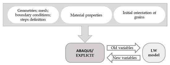
Figure 4.
A schematic of the interaction between the commercial software ABAQUS and the LW model.
2.6.3. ALAMEL Model
Shore and coworkers [34] used a FACET/ALAMEL scheme, where an analytical yield function limited to the subspace of the stress and strain rate in 2D, calibrated by the ALAMEL model, reproduced the plastic anisotropy for ASR simulations.
The FACET method presented by Van Houtte and coworkers [65] was developed to be coupled with multilevel models. It can be easily implemented in an FEA commercial software because it retrieves the plastic potential expression in terms of strain rate and stress.
The crystal plasticity ALAMEL is one of the multilevel models that can be combined with the FACET approach. This model, introduced by Van Houtte and coworkers [66], is a statistical Taylor–Bishop–Hill (TBH) model-based that treats the heterogeneity of plastic deformation by considering the cooperative deformation of grains along the shared boundaries. The original researches from Taylor–Bishop–Hill can be found in [67] and [68], respectively.
Shore and coworkers [34] implemented the FACET/ALAMEL techniques into the commercial software ABAQUS/Explicit using the python Application Programming Interface (API). The parametric model of the ASR process is extensively described in [56]. This type of coupled model has the advantage of reproducing the anisotropic macroscopic behavior associated with crystal plasticity without resorting to a substantial computational capability.
2.6.4. Visco-Plastic Self-Consistent (VPSC) Model
The visco-plastic self-consistent (VPSC) polycrystal model was introduced by Molinari and coworkers [69] and was further developed by Lebensohn and Tomé [70] to predict fully anisotropic responses. This model considers each grain as an ellipsoidal inclusion embedded in an effective visco-plastic medium. Weighted orientations define the polycrystal. These orientations correspond to the grains, and the weights represent volume fractions that reproduce the initial texture of the material.
The VPSC model is built upon the crystal plasticity mechanisms of slip and twinning systems activated by a resolved shear stress. It has in consideration grain interaction effects with its surroundings. As output, the VPSC model returns the macroscopic stress–strain behavior, considering hardening aspects, orientation, and shape change of each grain. It predicts the hardening and texture evolution during the plastic deformation. It must be noted that the VPSC model only accounts for plastic deformation. Nevertheless, the VPSC model has been successfully applied and proven accurate in predicting mechanical behavior and texture evolution during metal forming simulations [71].
Moreover, Walde and Riedel [72] implemented the VPSC in ABAQUS/Explicit via a user-subroutine (VUMAT) to simulate the earing formation during deep drawing processes. Later, Segurado and coworkers [73] introduced a VPSC-based UMAT in ABAQUS/Standard to simulate rolling of a face-center cubic (FCC) plate and the deformation under 4-point bending of textured hexagonal close-packed (HCP) bars. Soon after, Galán and coworkers [74] improved the algorithm of Segurado to reduce the computational cost without compromising the accuracy of the results. Their solution, called VPSC90, worked either as a stand-alone application or integrated into a UMAT for the ABAQUS/Standard solver. Additionally evolved from the work of Segurado and coworkers, Prakash et al. [75] revised the original VPSC-UMAT to function as a VPSC-VUMAT in Abaqus/Explicit. They applied the coupled models to predict the texture evolution of accumulative roll-bonded aluminum alloy sheets. It must be noted that combined VPSC-FE models are time-consuming. Thus, these approaches need more research to optimize the existing algorithms or develop new ones. As a stand-alone package, the VPSC has been used, for example, in References [30,31,76].
2.7. Simulation
After building the FE model, a solver will compute the results according to the inputs given. This task is performed solely by the computer. All parameters associated with the solver should be previously defined in the preprocessing step. The user has no intervention during this phase but may monitor the simulation progress.
2.8. Postprocessing
The postprocessing phase corresponds to the results visualization and interpretation. In this phase, it is possible to visualize displacements, stresses, strains, among other properties, in contour form, plot user-defined equations, or observe the deformation evolution during the simulation. Nevertheless, it is important to evaluate if the results are plausible. An FE model should be first validated by reliable experimental data, benchmarks, or other data found in the literature.
3. Summary and Final Remarks
The increasing interest in asymmetric rolling processes has heightened the need to further investigate the deformation texture evolution during such technique and subsequent mechanical responses of the rolled material. Early studies were only focused on observing and measuring the curvature effect due to the process’ asymmetry. The vertical bending of the material at the rolls’ exit is a clear drawback to the industrial implementation of such a technique. Consequently, it is only natural to have so many studies covering the subject. Additionally, it represents a significant issue in multi-stage asymmetric rolling procedures. In some FE models, an additional boundary condition enforces the material flatness between the rolling stages. However, this constraint fails to reproduce real rolling process occurrences. It would be interesting to design a device that could mechanically intervene to avoid bending. Nevertheless, curvature might be reduced by adjusting the rolls’ speed ratio or changing the entry angle.
In terms of computational analysis, as previously stated, the material model input considerably influences the outcomes. Many studies used simple constitutive laws or experimental stress–strain curves. However, these models cannot predict complex mechanical behavior. The texture evolution during plastic deformation changes the mechanical and metallurgical characteristics of the rolled material. The modified plastic anisotropy due to the forming process suggests a modified constitutive law. Thus, crystal-plasticity (CP) models coupled with FE analysis are necessary to predict the macroscopic response based on micro-scale plasticity models. Some of these CP models employ two-scale techniques that discretize the macro- and micro-continuum and relate both environments with mathematical formulations. At the crystal (micro) level, it is possible to increase the accuracy of the models by using measured SEM-EBSD data. Another CP approach employs a faceted scheme calibrated with virtual mechanical tests using the ALAMEL model. After the calibration phase, this approach allows obtaining results without much computational cost. Lastly, the VPSC model assumes a theoretical homogeneous environment (HEM) characterized by the average constitutive law of the polycrystal. The grain is embedded in the HEM. The formulation is based on the concept that the interaction between the grain and the HEM represents a good approximation for the interaction between the grain and all the other crystals. These CP models have proven accuracy in predicting texture evolution during metal forming. However, the VPSC model seems more robust regarding grain shape in comparison with ALAMEL [77].
Crystal plasticity numerical formulations can be stand-alone applications or implemented into commercial FE software. The second possibility is very captivating because users are already familiar with the graphical interfaces and functionalities, simplifying and accelerating the preprocessing phase of the finite element analysis.
The asymmetric rolling process improves the material microstructure and originates a nearly homogeneous crystallographic texture through the thickness. The enhanced material properties of asymmetrically rolled products represent significant advantages over symmetric rolling ones. Because of the strong relationship between texture evolution and mechanical behavior, it is crucial to invest in detailed studies. The FEA plays a key role in this last aspect. The findings reviewed in this paper showed that the FEM is well suited to predicting the influence of several parameters (such as speeds, roll diameters, sheet initial thickness, thickness reduction, grain orientation, etc.) on the ASR process and its products. The FEA results include strains, stresses, roll separating force, final geometry, textures evolution, among other variables, that the FE solver computes, sometimes aided by coupled subroutines. The FE model must be validated by comparing the numerical results with experiments, benchmarks, or data found in the literature. After the validation phase, the user may modify the process parameters to predict new outcomes as many times as it takes to achieve proper solutions. A numerical analysis offers invaluable information to optimize the ASR process or/and design a rolling mill suitable for certain specifications without resorting to laboratory apparatus. On the whole, the FEA is an essential tool to guide the implementation of the ASR process to an industrial production level.
Most studies on ASR that use coupled models with FEA to predict the mechanical behavior and texture evolution require many intermediate steps during and after the rolling process to build and run a proper analysis. Some studies need programming skills to exchange information between the FE code and the crystal plasticity (or similar) models. Coupled models of this nature need a lot of work and investment to become common commercial software features. It should be easy to call from a command line or, better yet, integrated on the GUI (graphical user interface), where the parameters and options available would be visible and easy to choose. The outputs should include all the results needed to make a complete analysis, with the respective visualization plots. However, before embedding a comprehensive crystal plasticity package in FE applications, it is still necessary to optimize the existing algorithms. The FEM has its difficulties for large deformation problems. The strong dependency on the mesh may compromise the accuracy of the results due to element distortion. This issue can be overcome with remeshing, but it has a high computational cost. Regarding the crystal plasticity models, more scientific study is required to attune results with real environments. Furthermore, is needed comprehension on the level of parametrization for the models, i.e., how much data is required to have an accurate prediction in a minimum amount of time. Additionally, more studies are needed on the simulation of thin strips produced by the ARS process.
Author Contributions
Conceptualization, investigation, writing—original draft preparation, A.G.; investigation, review and editing, G.V. All authors have read and agreed to the published version of the manuscript.
Funding
This work was supported by the projects POCI-01-0145-FEDER-032362 (PTDC/EME-ESP/32362/2017) financed by the Operational Program for Competitiveness and Internationalization, in its FEDER/FNR component, and the Portuguese Foundation of Science and Technology (FCT), in its State Budget component (OE), UID/EMS/00481/2019—FCT and CENTRO-01-0145-FEDER-022083—Centro Portugal Regional Operational Program (Centro2020), under the PORTUGAL 2020 Partnership Agreement, through the European Regional Development Fund.
Conflicts of Interest
The authors declare no conflict of interest.
References
- Shivpuri, R.; Chou, P.C.; Lau, C.W. Finite element investigation of curling in non-symmetric rolling of flat stock. Int. J. Mech. Sci. 1988, 30, 625–635. [Google Scholar] [CrossRef]
- Dyja, H.; Korczak, P.; Pilarczyk, J.W.; Grzybowski, J. Theoretical and experimental analysis of plates asymmetric rolling. J. Mater. Process. Tech. 1994, 45, 167–172. [Google Scholar] [CrossRef]
- Richelsen, A.B. Numerical analysis of asymmetric rolling accounting for differences in friction. J. Mater. Process. Tech. 1994, 45, 149–154. [Google Scholar] [CrossRef]
- Richelsen, A.B. Elastic-plastic analysis of the stress and strain distributions in asymmetric rolling. Int. J. Mech. Sci. 1997, 39, 1199–1211. [Google Scholar] [CrossRef]
- Lin, Z.C.; Shen, C.C. A three-dimensional finite element method for a nonisothermal aluminum flat strip rolling process. J. Mater. Eng. Perform. 1996, 5, 452–461. [Google Scholar] [CrossRef]
- Hwang, Y.M.; Chen, D.G.; Tzou, G.Y. Study on asymmetrical sheet rolling by the finite element method. J. Mech. 1999, 15, 149–155. [Google Scholar] [CrossRef]
- Knight, C.W.; Hardy, S.J.; Lees, A.W.; Brown, K.J. Investigations into the influence of asymmetric factors and rolling parameters on strip curvature during hot rolling. J. Mater. Process. Technol. 2003, 134, 180–189. [Google Scholar] [CrossRef]
- Lu, J.S.; Harrer, O.K.; Schwenzfeier, W.; Fischer, F.D. Analysis of the bending of the rolling material in asymmetrical sheet rolling. Int. J. Mech. Sci. 2000, 42, 49–61. [Google Scholar] [CrossRef]
- Lee, S.H.; Lee, D.N. Analysis of deformation textures of asymmetrically rolled steel sheets. Int. J. Mech. Sci. 2001, 43, 1997–2015. [Google Scholar] [CrossRef]
- Salimi, M.; Sassani, F. Modified slab analysis of asymmetrical plate rolling. Int. J. Mech. Sci. 2002, 44, 1999–2023. [Google Scholar] [CrossRef]
- Farhat-Nia, F.; Salimi, M.; Movahhedy, M.R. Elasto-plastic finite element simulation of asymmetrical plate rolling using an ALE approach. J. Mater. Process. Technol. 2006, 177, 525–529. [Google Scholar] [CrossRef]
- Akbari Mousavi, S.A.A.; Ebrahimi, S.M.; Madoliat, R. Three dimensional numerical analyses of asymmetric rolling. J. Mater. Process. Technol. 2007, 187. [Google Scholar] [CrossRef]
- Kim, J.K.; Jee, Y.K.; Huh, M.Y.; Jeong, H.T. Formation of textures and microstructures in asymmetrically cold rolled and subsequently annealed aluminum alloy 1100 sheets. J. Mater. Sci. 2004, 39, 5365–5369. [Google Scholar] [CrossRef]
- Kim, K.-H.H.; Lee, D.N.N. Analysis of deformation textures of asymmetrically rolled aluminum sheets. Acta Mater. 2001, 49, 2583–2595. [Google Scholar] [CrossRef]
- Tam, N.N.; Nakamura, Y.; Terao, T.; Kuramae, H.; Nakamachi, E.; Sakamoto, H.; Morimoto, H. Asymmetric rolling process simulations by using dynamic explicit crystallographic homogenized elasto/viscoplastic finite element method. Zair. Soc. Mater. Sci. Jpn. 2008, 57, 583–589. [Google Scholar] [CrossRef]
- Ji, Y.H.; Park, J.J. Development of severe plastic deformation by various asymmetric rolling processes. Mater. Sci. Eng. A 2009, 499, 14–17. [Google Scholar] [CrossRef]
- Sverdlik, M.; Pesin, A.; Pustovoytov, D.; Perekhozhikh, A. Numerical Research of Shear Strain in an Extreme Case of Asymmetric Rolling. In Advanced Materials Research; Trans Tech Publications Ltd.: Zurich, Switzerland, 2013; Volume 742, pp. 476–481. [Google Scholar]
- Hao, L.; Di, H.-s.; Gong, D.Y. Analysis of Sheet Curvature in Asymmetrical Cold Rolling. J. Iron Steel Res. Int. 2013, 20, 34–37. [Google Scholar] [CrossRef]
- Xie, H.B.; Manabe, K.; Jiang, Z.Y. A novel approach to investigate surface roughness evolution in asymmetric rolling based on three dimensional real surface. Finite Elem. Anal. Des. 2013, 74, 1–8. [Google Scholar] [CrossRef]
- Peng, L.; Lai, X.; Lee, H.J.; Song, J.H.; Ni, J. Friction behavior modeling and analysis in micro/meso scale metal forming process. Mater. Des. 2010, 31, 1953–1961. [Google Scholar] [CrossRef]
- Pesin, A.; Pustovoytov, D. Finite Element Simulation of Shear Strain During High-Ratio Differential Speed Rolling of Aluminum Alloy 5083. In Key Engineering Materials; Trans Tech Publications Ltd.: Zurich, Switzerland, 2016; Volume 716, pp. 700–707. [Google Scholar]
- Pesin, A.; Pustovoytov, D. Finite element simulation of extremely high shear strain during a single-pass asymmetric warm rolling of Al-6.2Mg-0.7Mn alloy sheets. Procedia Eng. 2017, 207. [Google Scholar] [CrossRef]
- Pustovoytov, D.; Pesin, A.; Biryukova, O. Finite element analysis of strain gradients in aluminium alloy sheets processed by asymmetric rolling. Procedia Manuf. 2018, 15, 129–136. [Google Scholar] [CrossRef]
- Pesin, A.; Pustovoytov, D.; Shveyova, T.; Vafin, R. Finite element simulation and comparison of a shear strain and equivalent strain during ECAP and asymmetric rolling. IOP Conf. Ser. Mater. Sci. Eng. 2018, 293. [Google Scholar] [CrossRef]
- Wroński, S.; Wierzbanowski, K.; Bacroix, B.; Chauveau, T.; Wróbel, M.; Rauch, A.; Montheillet, F.; Wroński, M. Texture heterogeneity of asymmetrically cold rolled low carbon steel. Arch. Met. Mater. 2009, 54, 89–102. [Google Scholar]
- Wroński, M.; Wierzbanowski, K.; Wróbel, M.; Wroński, S.; Bacroix, B. Effect of rolling asymmetry on selected properties of grade 2 titanium sheet. Met. Mater. Int. 2015, 21, 805–814. [Google Scholar] [CrossRef]
- Wronski, M.; Wierzbanowski, K.; Wronski, S.; Bacroix, B.; Lipinski, P. Experimental and finite element analysis of asymmetric rolling of 6061 aluminum alloy using two-scale elasto-plastic constitutive relation. Arch. Met. Mater. 2017, 62, 1991–1999. [Google Scholar] [CrossRef][Green Version]
- Nakamachi, E.; Kuramae, H.; Sakamoto, H.; Morimoto, H. Process metallurgy design of aluminum alloy sheet rolling by using two-scale finite element analysis and optimization algorithm. Int. J. Mech. Sci. 2010, 52, 146–157. [Google Scholar] [CrossRef]
- Kuramae, H.; Sakamoto, H.; Morimoto, H.; Nakamachi, E. Process metallurgy design for high-formability aluminum alloy sheet metal generation by using two-scale FEM. Procedia Eng. 2011, 10. [Google Scholar] [CrossRef]
- Tamimi, S.; Correia, J.P.; Lopes, A.B.; Ahzi, S.; Barlat, F.; Gracio, J.J. Asymmetric rolling of thin AA-5182 sheets: Modelling and experiments. Mater. Sci. Eng. A 2014, 603, 150–159. [Google Scholar] [CrossRef]
- Grácio, J.J.A.; Vincze, G.; Yoon, J.W.; Cardoso, R.P.R.; Rauch, E.F.; Barlat, F.G. Modeling the Effect of Asymmetric Rolling on Mechanical Properties of Al-Mg Alloys. Steel Res. Int. 2015, 86, 922–931. [Google Scholar] [CrossRef]
- Barlat, F.; Brem, J.C.; Yoon, J.W.; Chung, K.; Dick, R.E.; Lege, D.J.; Pourboghrat, F.; Choi, S.H.; Chu, E. Plane stress yield function for aluminum alloy sheets—Part 1: Theory. Int. J. Plast. 2003, 19, 1297–1319. [Google Scholar] [CrossRef]
- Marciniak, Z.; Kuczyński, K. Limit strains in the processes of stretch-forming sheet metal. Int. J. Mech. Sci. 1967, 9, 609–620. [Google Scholar] [CrossRef]
- Shore, D.; van Houtte, P.; Roose, D.; van Bael, A. Multiscale modelling of asymmetric rolling with an anisotropic constitutive law. Comptes Rendus Mecanique 2018, 346, 724–742. [Google Scholar] [CrossRef]
- Yekta, R.; Zohoor, H.; Motekallem, A. Analysis of asymmetric cold rolling using finite-element method for creating at sheet. Sci. Iran. 2018, 25, 3133–3140. [Google Scholar] [CrossRef]
- Hwang, Y.-M.; Tzou, G.-Y.I. Analytical and experimental study on asymmetrical sheet rolling. Int. J. Mech. Sci. 1997, 39, 289–303. [Google Scholar] [CrossRef]
- Qwamizadeh, M.; Kadkhodaei, M.; Salimi, M. Asymmetrical sheet rolling analysis and evaluation of developed curvature. Int. J. Adv. Manuf. Technol. 2012, 61, 227–235. [Google Scholar] [CrossRef]
- Feng, Y.; Liu, W.; Yang, T.; Du, F.; Sun, J. Theoretical and experimental analysis of the deformation zone and minimum thickness in single-roll-driven asymmetric ultrathin strip rolling. Int. J. Adv. Manuf. Technol. 2019, 104, 2925–2937. [Google Scholar] [CrossRef]
- Zanchetta, B.D.; da Silva, V.K.; Sordi, V.L.; Rubert, J.B.; Kliauga, A.M. Effect of asymmetric rolling under high friction coefficient on recrystallization texture and plastic anisotropy of AA1050 alloy. Trans. Nonferrous Met. Soc. China (Engl. Ed.) 2019, 29, 2262–2272. [Google Scholar] [CrossRef]
- Godoi, R.P.; Camilo Magalhães, D.C.; Avalos, M.; Bolmaro, R.E.; Sordi, V.L.; Kliauga, A.M. Microstructure, texture and interface integrity in sheets processed by Asymmetric Accumulative Roll-Bonding. Mater. Sci. Eng. A 2020, 771. [Google Scholar] [CrossRef]
- Kraner, J.; Fajfar, P.; Palkowski, H.; Kugler, G.; Godec, M.; Paulin, I. Microstructure and texture evolution with relation to mechanical properties of compared symmetrically and asymmetrically cold rolled aluminum alloy. Metals (Basel) 2020, 10, 156. [Google Scholar] [CrossRef]
- Zhang, T.; Li, L.; Lu, S.-H.; Gong, H.; Wu, Y.-X. Comparisons of Different Models on Dynamic Recrystallization of Plate during Asymmetrical Shear Rolling. Materials (Basel) 2018, 11, 151. [Google Scholar] [CrossRef]
- Zhang, T.; Wu, Y.X.; Gong, H.; Shi, W.Z.; Jiang, F.M. Flow stress behaviour and constitutive model of 7055 aluminium alloy during hot plastic deformation. Mechanika 2016, 22, 359–365. [Google Scholar] [CrossRef]
- Vincze, G.; Simões, F.J.P.; Butuc, M.C. Asymmetrical Rolling of Aluminum Alloys and Steels: A Review. Metals (Basel) 2020, 10, 1126. [Google Scholar] [CrossRef]
- Kraner, J.; Smolar, T.; Volsak, D.; Cvahte, P.; Godec, M.; Paulin, I. A review of asymmetric rolling. Materiali in Tehnologije 2020, 54, 731–743. [Google Scholar] [CrossRef]
- Ji, Y.H.; Park, J.J.; Kim, W.J. Finite element analysis of severe deformation in Mg-3Al-1Zn sheets through differential-speed rolling with a high speed ratio. Mater. Sci. Eng. A 2007, 454, 570–574. [Google Scholar] [CrossRef]
- Kim, W.J.; Hwang, B.G.; Lee, M.J.; Park, Y.B. Effect of speed-ratio on microstructure, and mechanical properties of Mg-3Al-1Zn alloy, in differential speed rolling. J. Alloy. Compd. 2011, 509, 8510–8517. [Google Scholar] [CrossRef]
- Wronski, M.; Wierzbanowski, K.; Wronski, S.; Bacroix, B.; Lipinski, P. Texture variation in asymmetrically rolled titanium. Study by Finite Element Method with implemented crystalline model. Int. J. Mech. Sci. 2014, 87, 258–267. [Google Scholar] [CrossRef]
- Pesin, A.; Chukin, M.; Korchunov, A.; Pustovoytov, D. Finite element modeling of shear strain in asymmetric and symmetric rolling in multi roll calibers. Procedia Eng. 2014, 81, 2469–2474. [Google Scholar] [CrossRef]
- Park, J.J. Finite-element analysis of severe plastic deformation in differential-speed rolling. Comput. Mater. Sci. 2015, 100, 61–66. [Google Scholar] [CrossRef]
- Uniwersał, A.; Wróbel, M.; Wierzbanowski, K.; Wroński, S.; Wroński, M.; Kalemba-Rec, I.; Sak, T.; Bacroix, B. Microstructure, texture and mechanical characteristics of asymmetrically rolled polycrystalline copper. Mater. Charact. 2016, 118, 575–583. [Google Scholar] [CrossRef]
- Angella, G.; Esfandiar Jahromi, B.; Vedani, M. A comparison between equal channel angular pressing and asymmetric rolling of silver in the severe plastic deformation regime. Mater. Sci. Eng. A 2013, 559, 742–750. [Google Scholar] [CrossRef]
- Jiang, Z.Y.; Tieu, A.K.; Zhang, X.M.; Lu, C.; Sun, W.H. Finite element simulation of cold rolling of thin strip. J. Mater. Process. Technol. 2003, 140, 542–547. [Google Scholar] [CrossRef]
- Ren, Z.; Xiao, H.; Liu, X.; Wang, G. Experimental and theoretical analysis of roll flattening in the deformation zone for ultra-thin strip rolling. Ironmak. Steelmak. 2018, 45, 805–812. [Google Scholar] [CrossRef]
- Wronski, M.; Wierzbanowski, K.; Bacroix, B.; Lipinski, P. Asymmetric rolling textures of aluminium studied with crystalline model implemented into FEM. IOP Conf. Ser. Mater. Sci. Eng. 2015, 82. [Google Scholar] [CrossRef]
- Shore, D.; Kestens, L.A.I.; Sidor, J.; van Houtte, P.; van Bael, A. Process parameter influence on texture heterogeneity in asymmetric rolling of aluminium sheet alloys. Int. J. Mater. 2016, 11, 297–309. [Google Scholar] [CrossRef]
- Gudur, P.P.; Salunkhe, M.A.; Dixit, U.S. A theoretical study on the application of asymmetric rolling for the estimation of friction. Int. J. Mech. Sci. 2008, 50, 315–327. [Google Scholar] [CrossRef]
- Wanheim, T.; Bay, N. A model for friction in metal forming processes. CIRP Ann. Manuf. Technol. 1978, 27, 189–194. [Google Scholar]
- Nielsen, C.V.; Bay, N. Overview of friction modelling in metal forming processes. Procedia Eng. 2017, 207, 2257–2262. [Google Scholar] [CrossRef]
- Nakamachi, E.; Tam, N.N.; Morimoto, H. Multi-scale finite element analyses of sheet metals by using SEM-EBSD measured crystallographic RVE models. Int. J. Plast. 2007, 23, 450–489. [Google Scholar] [CrossRef]
- Leffers, T. Computer simulation of the plastic deformation in face-centred cubic polycrystals and the rolling texture derived. Phys. Status Solidi 1968, 25, 337–344. [Google Scholar] [CrossRef]
- Wierzbanowski, K.; Jura, J.; Haije, W.G.; Helmholdt, R.B. F.C.C. Rolling Texture Transitions in Relation to Constraint Relaxation. Cryst. Res. Technol. 1992, 27, 513–522. [Google Scholar] [CrossRef]
- Wierzbanowski, K.; Baczmański, A.; Lipiński, P.; Lodini, A. Elasto-plastic models of polycrystalline material deformation and their applications. Arch. Met. Mater. 2007, 52, 77–86. [Google Scholar]
- Wierzbanowski, K.; Wroński, M.; Leffers, T. F.C.C. Rolling Textures Reviewed in the Light of Quantitative Comparisons between Simulated and Experimental Textures. Crit. Rev. Solid State Mater. Sci. 2014, 39, 391–422. [Google Scholar] [CrossRef]
- Van Houtte, P.; Yerra, S.K.; van Bael, A. The Facet method: A hierarchical multilevel modelling scheme for anisotropic convex plastic potentials. Int. J. Plast. 2009, 25, 332–360. [Google Scholar] [CrossRef]
- Van Houtte, P.; Li, S.; Seefeldt, M.; Delannay, L. Deformation texture prediction: From the Taylor model to the advanced Lamel model. Int. J. Plast. 2005, 21, 589–624. [Google Scholar] [CrossRef]
- Taylor, G.I. Plastic Strain in Metals. J. Inst. Met. 1938, 62, 307–324. [Google Scholar]
- Bishop, J.F.W.; Hill, R. CXXVIII. A theoretical derivation of the plastic properties of a polycrystalline face-centred metal. Philos. Mag. J. Sci. Ser. 7 1951, 42, 1298–1307. [Google Scholar] [CrossRef]
- Molinari, A.; Canova, G.R.; Ahzi, S. A self consistent approach of the large deformation polycrystal viscoplasticity. Acta Met. 1987, 35, 2983–2994. [Google Scholar] [CrossRef]
- Lebensohn, R.A.; Tomé, C.N. A self-consistent anisotropic approach for the simulation of plastic deformation and texture development of polycrystals: Application to zirconium alloys. Acta Met. Mater. 1993, 41, 2611–2624. [Google Scholar] [CrossRef]
- Takajo, S.; Vogel, S.C.; Tomé, C.N. Viscoplastic self-consistent polycrystal modeling of texture evolution of ultra-low carbon steel during cold rolling. Model. Simul. Mater. Sci. Eng. 2019, 27, 045003. [Google Scholar] [CrossRef]
- Walde, T.; Riedel, H. Simulation of earing during deep drawing of magnesium alloy AZ31. Acta Mater. 2007, 55, 867–874. [Google Scholar] [CrossRef]
- Segurado, J.; Lebensohn, R.A.; Llorca, J.; Tomé, C.N. Multiscale modeling of plasticity based on embedding the viscoplastic self-consistent formulation in implicit finite elements. Int. J. Plast. 2012, 28, 124–140. [Google Scholar] [CrossRef]
- Galán, J.; Verleysen, P.; Lebensohn, R.A. An improved algorithm for the polycrystal viscoplastic self-consistent model and its integration with implicit finite element schemes. Model. Simul. Mater. Sci. Eng. 2014, 22. [Google Scholar] [CrossRef]
- Prakash, A.; Nöhring, W.G.; Lebensohn, R.A.; Höppel, H.W.; Bitzek, E. A multiscale simulation framework of the accumulative roll bonding process accounting for texture evolution. Mater. Sci. Eng. A 2015, 631, 104–119. [Google Scholar] [CrossRef]
- Dhinwal, S.S.; Toth, L.S. Unlocking deformation path in asymmetric rolling by texture simulation. Materials (Basel) 2020, 13, 101. [Google Scholar] [CrossRef]
- Xie, Q.; Eyckens, P.; Vegter, H.; Moerman, J.; van Bael, A.; van Houtte, P. Polycrystal plasticity models based on crystallographic and morphologic texture: Evaluation of predictions of plastic anisotropy and deformation texture. Mater. Sci. Eng. A 2013, 581, 66–72. [Google Scholar] [CrossRef]


Publisher’s Note: MDPI stays neutral with regard to jurisdictional claims in published maps and institutional affiliations. |
© 2021 by the authors. Licensee MDPI, Basel, Switzerland. This article is an open access article distributed under the terms and conditions of the Creative Commons Attribution (CC BY) license (https://creativecommons.org/licenses/by/4.0/).