
Corrosion of Metals and Nickel-Based Alloys in Liquid Bismuth–Lithium Alloy

 , and
, and
Abstract
1. Introduction
2. Materials and Methods
2.1. Materials
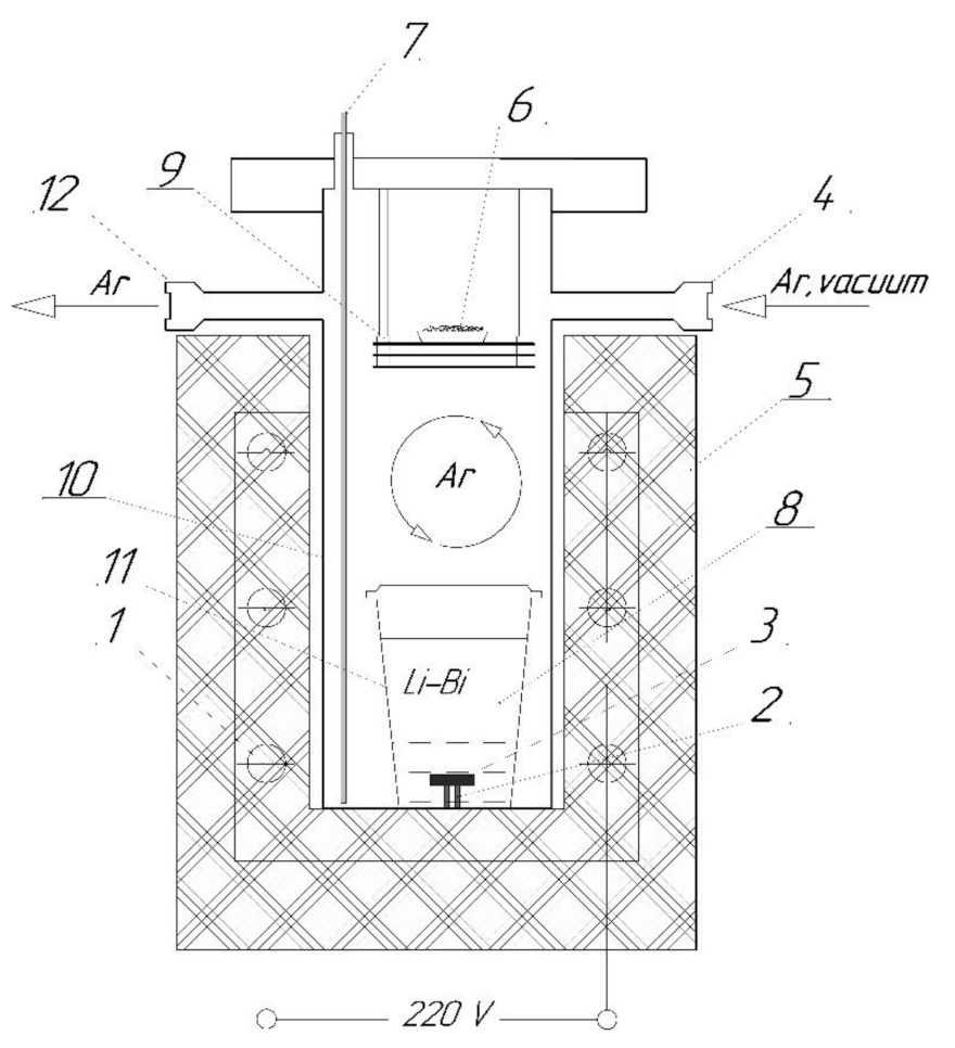
2.2. Corrosion Tests
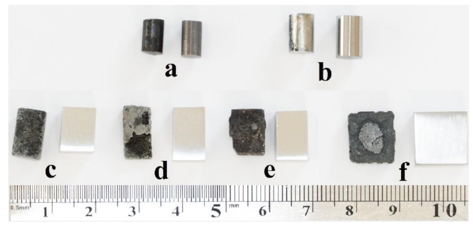
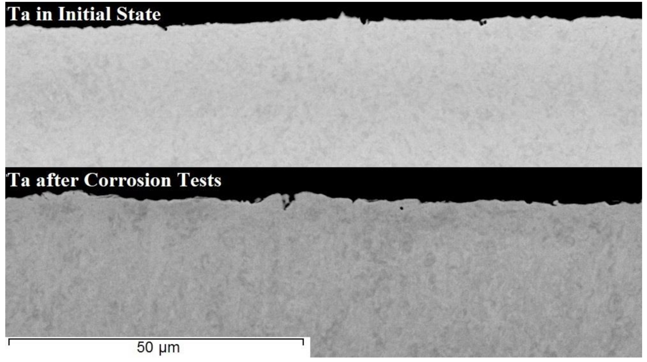
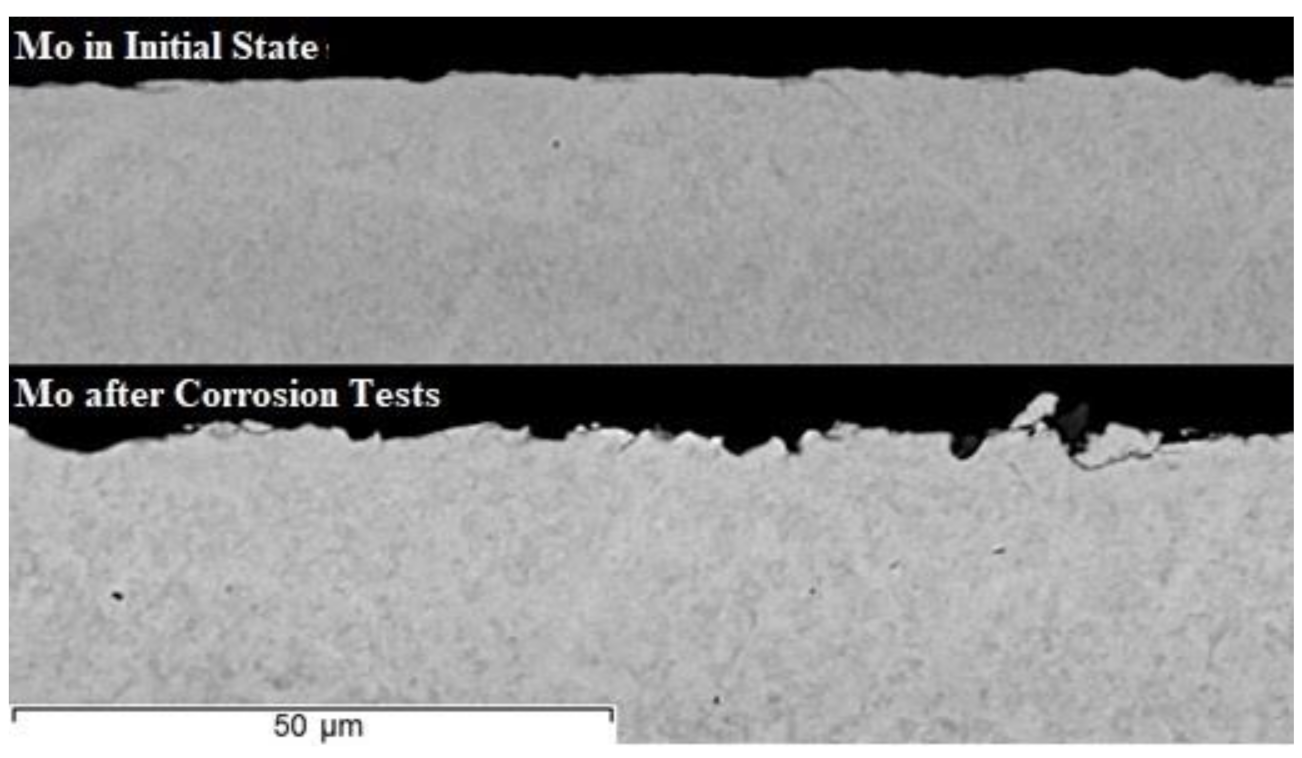
3. Results and Discussion
4. Conclusions
Author Contributions
Funding
Institutional Review Board Statement
Informed Consent Statement
Data Availability Statement
Conflicts of Interest
References
- International Atomic Energy Agency. Liquid Metal Cooled Reactors: Experience in Design and Operation; IAEA-TECDOC-CD-1569; IAEA: Vienna, Austria, 2008. [Google Scholar]
- Subbotin, V.I.; Arnol’dov, M.N.; Kozlov, F.A.; Shimkevich, A.L. Liquid-Metal Coolants for Nuclear Power. At. Energy 2002, 92, 29–40. [Google Scholar] [CrossRef]
- Zrodnikov, A.V.; Gromov, B.F.; Grigoryv, O.G.; Dedoul, A.V.; Toshinsky, G.I.; Dragunov, Y.G.; Stepanov, V.S. Use of Russian technology of ship reactors with lead-bismuth coolant in nuclear power (IAEA-TECDOC-1172). IAEA 2000, 31, 127–155. [Google Scholar]
- Zhang, X.D.; Liu, J. Perspective on liquid metal enabled space science and technology. Sci. China Technol. Sci. 2020, 63, 1127–1140. [Google Scholar] [CrossRef]
- International Atomic Energy Agency. Spent Fuel Reprocessing Options; IAEA-TECDOC-CD-1587; IAEA: Vienna, Austria, 2009. [Google Scholar]
- Weisenburger, A.; Lang, F.; Müller, G. Material and experimental issues related to the use of liquid metals as heat transfer media for CSP tower receivers. AIP Conf. Proc. 2018, 2033, 080005. [Google Scholar]
- Zhuk, N.P. Corrosion and Metal Protection Theory Course; Alyans: Moscow, Russia, 2006. [Google Scholar]
- Borishansky, V.M. Liquid metal coolants; Atomizdat: Moscow, Russia, 1967. [Google Scholar]
- Shrier, L.L.; Jarman, R.A.; Burstein, G.T. Mechanisms of Liquid metal Corrosion. In Corrosion (Metal/Environment Reactions), 3rd ed.; Reed Educational and Professional Publishing Ltd.: Butterworh-Heinemann Linacn House, Jordan Hill, Oxford, UK, 1994; Volume 1, pp. 464–465. [Google Scholar]
- Tsuprun, L.I.; Tarytina, M.I. Metallurgy of Nuclear Energy; Gostekhizdat: Moscow, Russia, 1956. [Google Scholar]
- Joseph, B.; Picat, M.; Barbier, F. Liquid metal embrittlement: A state-of-the-art appraisal. Eur. Phys. J. Appl. Phys. 1999, 5, 19–31. [Google Scholar] [CrossRef]
- Pereiro-López, E.; Ludwig, W.; Bellet, D. Discontinuous penetration of liquid Ga into grain boundaries of Al polycrystals. Acta Mater. 2004, 52, 321–332. [Google Scholar] [CrossRef]
- Pereiro-López, E.; Ludwig, W.; Bellet, D.; Lemaignan, C. In situ investigation of Al bicrystal embrittlement by liquid Ga using synchrotron imaging. Acta Mater. 2006, 54, 4307–4316. [Google Scholar] [CrossRef]
- Sigle, W.; Richter, G.; Ruhle, M.; Schmidt, S. Insight into the atomic-scale mechanism of liquid metal embrittlement. Appl. Phys. Lett. 2006, 89, 121911. [Google Scholar] [CrossRef]
- Asl, K.M.; Luo, J. Impurity effects on the intergranular liquid bismuth penetration in polycrystalline nicke. Acta Mater. 2012, 60, 149–165. [Google Scholar] [CrossRef]
- James, J.A.; Trotman, J. Corrosion of steels in liquid bismuth and lead. J. Iron Steel Inst. 1960, 194, 319–323. [Google Scholar]
- Horsley, G.W.; Maskrey, J.T. The corrosion of 2.25Cr–1Mo steel by liquid bismuth. J. Iron Steel Inst. 1958, 189, 139–148. [Google Scholar]
- Dawe, D.W.; Parry, G.W.; Wilson, G.W. Study of compatibility of some creep resistant steels with liquid bismuth in non-isothermal systems. J. Br. Nucl. Energy Conf. 1960, 5, 24–29. [Google Scholar]
- Stephan, H.R.; Koshuba, W.J. Circulation of Bismuth at Elevated Temperatures, Progress Report on Project 2-01; NEPA-1675; NEPA Division Fairchild Engine and Airplane Corporation: New York, NY, USA, 1950. [Google Scholar]
- Polovov, I.B.; Abramov, A.V.; Alimgulov, R.R.; Zolotarev, D.A.; Trubcheninova, A.I.; Gibadullina, A.F.; Volkovich, V.A.; Zhilyakov, A.Y.; Khotinov, V.A.; Belikov, S.V. Corrosion of Metallic Materials in Molten FLiNaK. ECS Trans. 2020, 98, 453–462. [Google Scholar] [CrossRef]
- Balandin, Y.F.; Markov, V.G. Structural Materials for Installations with Liquid Metal Heat Carriers; Sudpromgiz: Leningrad, Russia, 1961. [Google Scholar]
- Okamoto, H.; Schlesinger, M.E.; Mueller, E.M. (Eds.) Bi (Bismuth) Binary Alloy Phase Diagrams, Alloy Phase Diagrams. In ASM Handbook; ASM International: Materials Park, OH, USA, 2016; Volume 3, pp. 201–217. [Google Scholar]
- Lyakisheva, N.P. (Ed.) State Diagrams of Double Metal Systems: Handbook; Elseiver Ltd.: Amsterdam, The Netherlands, 1996; Volume 1. [Google Scholar]
- Garg, S.P.; Krishnamurthy, N. The Bi-Ta (bismuth-tantalum) system. JPE 1992, 13, 269–270. [Google Scholar] [CrossRef]
- Dybkov, V.I.; Barmak, K.; Lengauer, W.; Gas, P. Interfacial interaction of solid nickel with liquid bismuth and Bi–base alloys. J. Alloys Compd. 2005, 389, 61–74. [Google Scholar] [CrossRef]
- Polovov, I.B.; Abramov, A.V.; Gibadullina, A.F.; Alimgulov, R.R.; Karpov, V.V.; Zhilyakov, A.Y.; Khotinov, V.A. The effect of microstructure on the corrosion resistance of VDM® alloy C-4 in molten salts. J. Alloys Compd. 2019, 810, 151758. [Google Scholar] [CrossRef]
- Reed, E.L. Stability of Refractories in Liquid Metals. J. Am. Ceram. Soc. 1954, 37, 146–152. [Google Scholar] [CrossRef]
- Yamaki, E.; Ginestar, K.; Martinelli, L. Dissolution mechanism of 316L in lead–bismuth eutectic at 500°C. Corros. Sci. 2011, 53, 3075–3085. [Google Scholar] [CrossRef]
- Martín-Muñoz, F.J.; Soler-Crespo, L.; Gómez-Briceño, D. Corrosion behaviour of martensitic and austenitic steels in flowing lead–bismuth eutectic. J. Nucl. Mater. 2011, 416, 87–93. [Google Scholar] [CrossRef]
- Kurata, Y.; Sato, H.; Yokota, H.; Suzuki, T. Applicability of Al-Powder-Alloy Coating to Corrosion Barriers of 316SS in Liquid Lead-Bismuth Eutectic. Jpn. Inst. Metals. Mater. Trans. 2011, 52, 1033–1040. [Google Scholar] [CrossRef]
- Barbier, F.; Rusanov, A. Corrosion behavior of steels in flowing lead–bismuth. J. Nucl. Mater. 2001, 296, 231–236. [Google Scholar] [CrossRef]
- Kurata, Y.; Saito, S. Temperature Dependence of Corrosion of Ferritic/Martensitic and Austenitic Steels in Liquid Lead-Bismuth Eutectic. Jpn. Inst. Metals. Mater. Trans. 2009, 50, 2410–2417. [Google Scholar] [CrossRef]
- Mueller, G.; Schumacher, G.; Weisenburger, A.; Heinzel, A.; Zimmermann, F.; Tomohiro, F.; Kazumi, A. Study on Pb/Bi Corrosion of Structural and Fuel Cladding Materials for Nuclear Applications; ASM International: Materials Park, OH, USA, 2004. [Google Scholar]
- Dömstedt, P.; Lundberg, M.; Szakalos, P. Corrosion Studies of Low-Alloyed FeCrAl Steels in Liquid Lead at 750 °C. Oxid. Met. 2019, 91, 511–524. [Google Scholar] [CrossRef]
- Das, C.; Kishore, R.; Fotedar, R. Corrosion Compatibility Studies of Stainless Steel 304L in Flowing Liquid Lead Bismuth Eutectic. Trans. Indian Inst. Met. 2011, 64, 417–423. [Google Scholar] [CrossRef]
- Garg, S.P.; Venkatraman, M.; Krishnamurthy, N. Binary Alloy Phase Diagrams, 2nd ed.; Massalski, T.B., Ed.; Materials Information Society: Materials Park, OH, USA, 1990; Volume 3. [Google Scholar]
- Subramanian, P.R. Li-Mo (Lithium-Molybdenum). In Binary Alloy Phase Diagrams, 2nd ed.; Massalski, T.B., Ed.; ASM International: Materials Park, OH, USA, 1990; Volume 3, pp. 2446–2447. [Google Scholar]
- Gryaznov, G.M.; Evtikhin, V.A.; Lyublinsky, I.E. Materials Science of Liquid Metal Systems of Thermonuclear Reactors; Energoatomizdat: Moscow, Russia, 1989. [Google Scholar]
- Kieffer, R.; Windisch, S.; Nowotny, H. Niobium–Tantalum Infiltrated Alloys. Metall 1963, 17, 669–677. [Google Scholar]
- Brewer, L.; Lamoreaux, R.H. Molybdenum, Physico-chemical Properties of its Compounds and Alloys; Atomic Energy Review; Special Issue No.7; IAEB: Vienna, Austria, 1980. [Google Scholar]
- Baren, M.R. The Ag-Mo (silver-molybdenum) system. Bull. Alloy Phase Diagr. 1990, 11, 548–549. [Google Scholar] [CrossRef]
- Simon, N.; Terlain, A.; Flament, T. The compatibility of austenitic materials with liquid Pb–17Li. Corros. Sci. 2001, 43, 1041–1052. [Google Scholar] [CrossRef]


| Element | Fe | Ni | Mo | W | Ta | Nb | Cr | Cu | Mn | Si | Zr |
|---|---|---|---|---|---|---|---|---|---|---|---|
| IMC | none | BiNi Bi3Ni | none | none | none | none | none | none | MnBi | none | ZrBi2 ZrBi Zr3Bi2 Zr3Bi Zr3Bi |
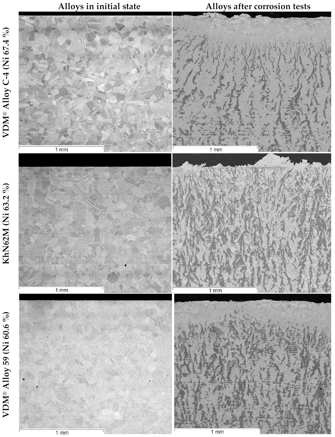
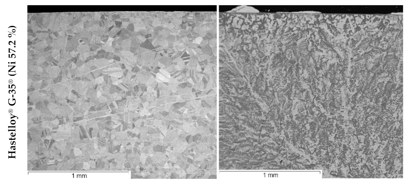
| Alloy | Ni | Cr | Mo | Fe | Mn | Ti | Al | Si | S | C | P | Cu | W |
|---|---|---|---|---|---|---|---|---|---|---|---|---|---|
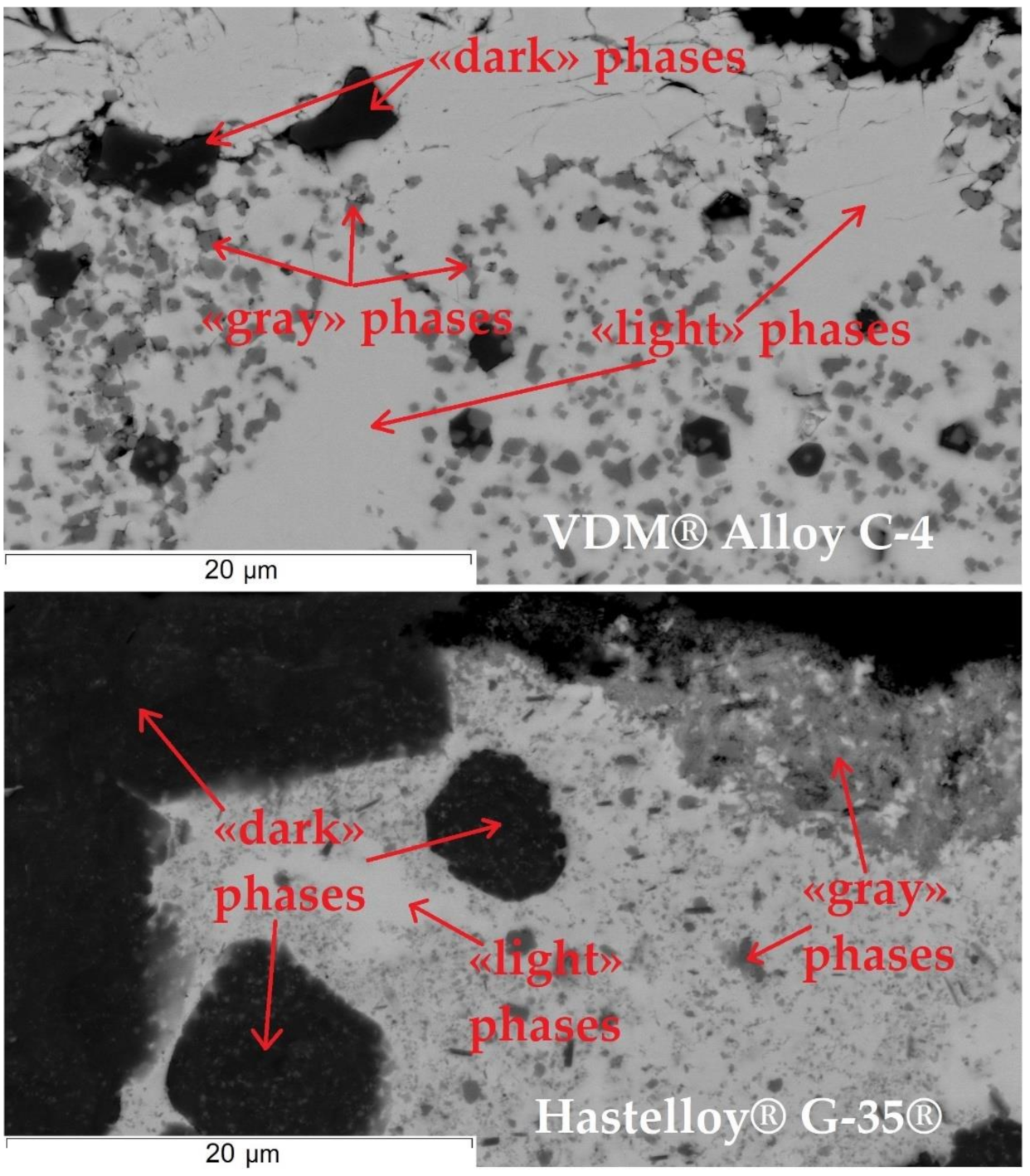
| VDM® Alloy C-4 | base | 16.1 | 15.6 | 0.84 | 0.02 | 0.01 | — | 0.016 | 0.002 | 0.003 | 0.002 | — | — |
| Hastelloy® G-35® | base | 33.12 | 8.22 | 0.78 | 0.22 | <0.01 | 0.19 | 0.04 | <0.002 | 0.012 | 0.003 | 0.03 | 0.11 |
| KhN62M | base | 23.21 | 12.78 | 0.47 | 0.03 | 0.08 | 0.11 | 0.06 | 0.003 | 0.005 | 0.004 | — | — |
| VDM® Alloy 59 | base | 22.6 | 15.4 | 0.9 | 0.19 | — | 0.23 | 0.02 | <0.002 | 0.002 | 0.002 | <0.01 | — |
| System | Element | Element Content (wt.%) | |
|---|---|---|---|
| XRF | ICP–AES | ||
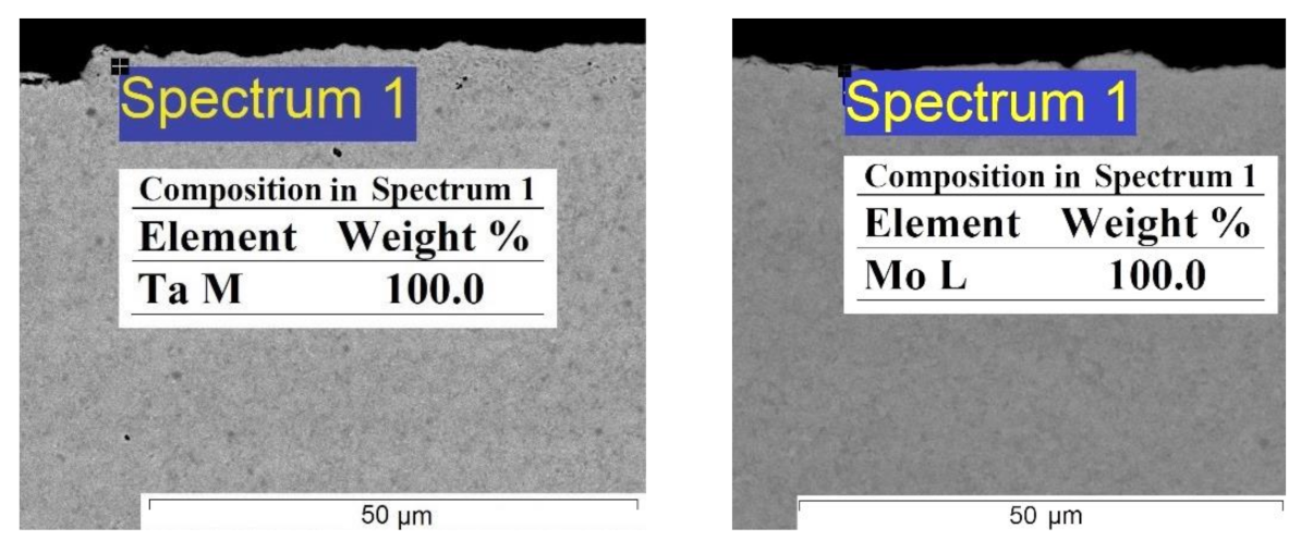
| (Bi–Li)–Ta | Ta | 0.0016 ± 0.0001 | 0.0017 ± 0.0001 |
| (Bi–Li)–Mo | Mo | 0.0011 ± 0.0001 | 0.0010 ± 0.0001 |
| System | Corrosion Rate (mm/year) According to | ||
|---|---|---|---|
| Sample’s Weight Loss | XRF Analysis | ICP–AES Analysis | |
| Ta in (Bi–Li) | 0.022 ± 0.003 | 0.092 ± 0.006 | 0.098 ± 0.005 |
| Mo in (Bi–Li) | 0.013 ± 0.002 | 0.071 ± 0.006 | 0.068 ± 0.005 |
| Alloys | Corrosion Product Content (wt. %) Determined by | ||||||
|---|---|---|---|---|---|---|---|
| XRF | ICP–AES | ||||||
| Ni | Cr | Mo | Ni | Cr | Mo | Fe | |
| Hastelloy® G-35® | 0.83 | 0.001 | <0.001 | 0.95 | 0.0002 | 0.0001 | <0.001 |
| KhN62M | 0.77 | <0.001 | <0.001 | 0.86 | 0.0001 | 0.0001 | <0.001 |
| VDM® Alloy C-4 | 1.02 | <0.001 | <0.001 | 1.12 | 0.0002 | 0.0002 | <0.001 |
| VDM® Alloy 59 | 1.04 | <0.001 | <0.001 | 1.21 | 0.0002 | 0.0001 | <0.001 |
| Alloy | Corrosion Rate (mm/year) According to | |
|---|---|---|
| XRF | ICP–AES | |
| Hastelloy® G-35® | 27 | 32 |
| KhN62M | 30 | 34 |
| VDM® Alloy 59 | 30 | 36 |
| VDM® Alloy C-4 | 32 | 35 |
Publisher’s Note: MDPI stays neutral with regard to jurisdictional claims in published maps and institutional affiliations. |
© 2021 by the authors. Licensee MDPI, Basel, Switzerland. This article is an open access article distributed under the terms and conditions of the Creative Commons Attribution (CC BY) license (https://creativecommons.org/licenses/by/4.0/).
Share and Cite
Abramov, A.V.; Alimgulov, R.R.; Trubcheninova, A.I.; Zhilyakov, A.Y.; Belikov, S.V.; Volkovich, V.A.; Polovov, I.B. Corrosion of Metals and Nickel-Based Alloys in Liquid Bismuth–Lithium Alloy. Metals 2021, 11, 791. https://doi.org/10.3390/met11050791
Abramov AV, Alimgulov RR, Trubcheninova AI, Zhilyakov AY, Belikov SV, Volkovich VA, Polovov IB. Corrosion of Metals and Nickel-Based Alloys in Liquid Bismuth–Lithium Alloy. Metals. 2021; 11(5):791. https://doi.org/10.3390/met11050791
Chicago/Turabian StyleAbramov, Aleksandr V., Ruslan R. Alimgulov, Anastasia I. Trubcheninova, Arkadiy Yu. Zhilyakov, Sergey V. Belikov, Vladimir A. Volkovich, and Ilya B. Polovov. 2021. "Corrosion of Metals and Nickel-Based Alloys in Liquid Bismuth–Lithium Alloy" Metals 11, no. 5: 791. https://doi.org/10.3390/met11050791
APA StyleAbramov, A. V., Alimgulov, R. R., Trubcheninova, A. I., Zhilyakov, A. Y., Belikov, S. V., Volkovich, V. A., & Polovov, I. B. (2021). Corrosion of Metals and Nickel-Based Alloys in Liquid Bismuth–Lithium Alloy. Metals, 11(5), 791. https://doi.org/10.3390/met11050791